1
SERVICE INFORMATION
AUDIO TELEX
DCM500
POWER AMPLIFIER
CONTENTS:
OPERATION MANUAL
CIRCUIT DESCRIPTION
SET-UP / TEST PROCEDURE
SCHEMATIC DIAGRAMS
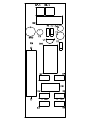
PCB OVERLAYS
COMPONENT LISTS
Australian Monitor
1 Clyde Street, Silverwater NSW 2128 Australia
+61 2 9647 1411
www.australianmonitor.com.au
AMlilrDlilil@
() o n4 lw u N I cAT
..........',..'........'.'''.'.'.'......H'.
ft{tTl
I O N SPrY
Lro
..tlllii6'ui0.li'i.iii:i."",i"-"i';i''itititt;;'.
'.'....'.....'.'...'..'...'.'.'.'..'..'.'.'.'.'.'.'.'.'.'.'.'.'.':.'.'.'.'.....'.':
:':':
:::::::.: :.rel$t
Audio Telex Communications Pty Ltd
ACN 001345482 lncorporated ln NSW
DCM500, 500 Watt Power Amplifier
Product Description
The DCM500 is a 500 watt power amplifier in a two rack unit (2RLI) chassis suitable for table or direct 19" rack
mounting. The DCM500 has outputs for 70 & 100 volts and 4 ohms. It has a balanced input of 10K ohms. The DCM500 will
operate from 240 V AC @ 50 IIz or I I 0 VAC @ 60 Hz (not user selectable, internal, factory adjushent only, specifi at the time
of ordering) or 24 VDC and will meet it's full performance specification on either voltage supply. The DCM500 also features a
DC battery trickle charge facility, slow start on powering up (to reduce inrush current problems), auto-sensing ftn cooling, plus
overload short circuit and over ternperature protection. The maximum recommended load for the DCM500 is 20 ohms.
lnitial Set Up
There is an unlabelled, screwdriver adjustable output level control located centrally on the front panel of the DCM500.
Turning this control in the clockwise direction will increase the power output, turning this comtrol in a counter-clockwise
direction will reduce the power output. The ftctory default setting for this conkol is such that a I volt input will give a 100 volt
output.
Front Panel Gontrols
Output Level: The output level control is unlabelled, r@essed (screwdriver adjustable) and is located in the centre of the
front panel, just to the right of the DCM Series logo. Tuming the control clockwise will increase the output of the DCM500
towards it's manimum output level wtrile tuming the control counter-clockwise will decrease the output level. Adjust this control
for the desired output level depending on the level of the input signal (from a mixer or other signal source). The factory defrult
setting for this control is such that a
I volt input will
give a 100 volt output.
POWef SWitch: The rocker switch located in the front centre of the panel turns AC power on to the DCM500. Rocking the
power switch to the right to turns the AC powetr 'on'. When the AC power is 'on', a gree,lr LED will glow in the amplifier status
display windorv. Please note that this switch does not switch DC voltage. If a DC voltage supply is connected to the DCM500, the
amplifier will operate as sfi)n as the connection is made, regardless of the position of the AC power switch. If both an AC and
DC voltage supply are connected and you rock the AC power switch to the 'off position, the DCM500 will automatically
continue to op€rate normally from the DC supply (and the 'mains failure' LED in the amplifier status display window will also
glow undo these comditions; see the amplifio status display window section under Frurt Panel Cmtols later in this manual).
Gooling Fans (Air lntake): rhe cooling fans (two installed in the case of the DCM500) are ternperature sensitive and
only switch orr when the temperature of the DCM500 had reached a pre-determined range. The fans will stay on and only switch
off again mce the temperature of the DCM500 has fallen below a pre-determined level. So, the ftct that the fans are not
operating at any time (and most noticeably to the operator at turn-on) does not mean that the amplifier is faulty in any way, just
that it is o'perating within a temperature range that does not need frn cooling for adequate heat dissipation. If the DCM500 is
operating curtinually at c.onservative levels and proper load conditions, it is possible that the cooling fans will not switch on at
anytime during normal operation. When operating, the fans cause air flow from the front to the rear of the DCM500.
Continuednext page3
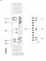
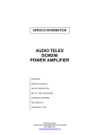
Amplifier Status Display Window:
The status display window highlights the operating conditions of the DCM500.
Please refer to Figwe #1 on the back page of this instruction sheet with numerical reference as follows:
High Temperature: firis red LED glows if the fan has failed and the amplifio has been shut down by its' temperature
control circuity. If this LED is glowing and the fans have not failed, it means that the amplifier is operating in an ambient
environment that it naturally too hot for fan cooling to make any difference to the temperature of the amplifier.
PoWef:
This LED glows green
if AC power is switched
on to the DCM500. Note that this LED does not indicate the
pres€nce ofa DC supply voltage
lUlains Failure: The LED glows red if there is a failure in the AC mains power supply. However, this LED
glow if there is a DC supply voltage present. If no DC supply voltage is present then this LED will not glow.
will only
Output Level VU
A 10 segment LED W meter is provided to give an indication of the output signal level of
the DCM500 from -25 to +3 dB. For normal operation the LED's should oscillate in and out of the red zone. If the LED's in
the red zone are lit continually, the,n the output level control (or the level of the input signal to the DCM500) should be
adjusted to reduce the output level. Too much output level can cause distortion and possible damage to the connected speaker
lleter:
qystem.
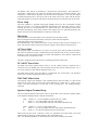
Rear Panel Connections
Please refer to Figure #2 on the back page of these instructions with numerical references as follows:
3 pin lEC, AC mains power inlet. The operating voltage is 240 VAC @ 50llzor l t0
@ 60 rIz. The AC
power voltage level is not externally user selectable but is ftctory pre-set (via transformo selection). The inl* is equipped
with an inbuilt AC fuse holder fitted with a l0 Amp slow blow fuse plus one spare fuse. Power consumption is 800 VA.
Please ensure that the mains power cord is disconnected before attempting to check or replace this fuse.
vtc
Output terminal strip
. Reading from left to right these connections are as follows:
Common for low impedance
4 Ohms
Common for constant voltage systems
70 volts
100 volts
24 VDC power connectio[.
The left side red post is the + (positive) terminal while the right side black posr is the
- (negative) terminal. The DC current drain is 30 Amps, maximum at full power. This socket also provides trickle charge to a
DC battery supply (if connected) when the DCM500 is operated from AC mains power. The level of trickle charge is 30b me"
maximum.
Twin DC low voltage, fuse receptacles.
Access the DC tuses is by turning the cap half a turn count€rclockwisewith a screwdriver. The value of the fuses is 35 Amps. Pleasc ensure that the AC powerswitch is in the.ofr
position and that the mains power cord is disconnected before attenpting to check or replace this frrse
lnput (& parallel_output) XLR signal connectiolr. The input to the DCM500 is ransformer
balanced @
10K ohms. The pin configuration of both sockets is as follows: pin #l-earth; pin #2-active (high, +); pin #3-active (lol", -j.
The output socket is to allow the original input signal to be fed on to another amplifier. As these trvo sockets are wired in
passive parallel, the failure of any one amplifier will not affect the sigrral flowing through that amplifier to anotho amplifier.
ll||lltl!!!
ltltllll!!l
lllrltllrll
E
lol{.o
Ei"=
tel
lglt'.
\l
-Hi;;
dl
-:::f
c::------------__f
(_-------------
-::-----------)
-_-:-_---r
-c_:_-----------l
-:l
-__-:f
--
U
o
(tl
O
o
BI
--------.)
!ll!!r!!lll
lll!rllt!!l
lllliltllll
o'l
ill
ol
ol
ol
ol
DCM Series
Circuit Description
The DCM series are power amplifiers designed for commercial installations. They can be used for
either low impedance (4 ohm/8 ohm) or constant voltage line speakers (100v/70v). These amplifiers
can be mounted in a standard 19” equipment rack or they can be used on a shelf or table. The DCM
series feature line level input (with parallel output) and are normally used with mixers, mixer amplifiers
or other power amplifiers. The DCM series will operate from mains voltage or 24VDC. The DCM
series also feature a DC battery trickle charge facility, auto-sensing fan cooling, plus overload, short
circuit and over temperature protection.
Power Switch
This switch controls the switching of AC power to the amplifier. A blue ‘On’ LED will indicate
whether the amplifier is switched on or off. This switch will not switch DC power on or off in DC
operation. In DC operation mode, the amplifier is always on and the blue power LED will always be
illuminated. If both AC and DC voltage supply are connected and the AC power switch is in the off
position, the amplifier will continue to operate normally from the DC supply and the mains fail LED
will indicate.
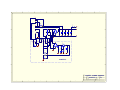
Level Control
The output level control is located in the centre of the front panel. It is a fully recessed screwdriver
adjustable pot. Turning this pot cw will increase the gain of the amplifier. At maximum setting the
input sensitivity is 300mV. The amplifier ships from the factory with the sensitivity set to 1V.
Amplifier Status Display
This VU meter indicates the output level of the amplifier. The sensing for the circuit is taken on the
amplifier side of the output transformer. The 0dB level is referenced to 100V. This is an RMS meter,
not a peak meter.
Protect
The protect LED will illuminate when the amplifier cuts out because of either over current or high
temperature. The amplifier will switch back on after approx 4 sec for an over current trip. The amplifier
will switch back on after the amplifier has cooled to 60degC for a thermal trip.
Limiter
The limiter is a hard limiter with an attack time of about 1msec. It is defeatable by removing the jumper
on the solder side of the front pcb. This however is not recommended as voltage overload and speaker
transformer current saturation may cause the amplifier to cut out under normal program material.
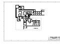
Current Limit and Setup
Current limit is controlled by a microprocessor (PIC12C509A). The detection is done by sensing
voltage across the emitter resistors. Trimpot P1 on the front pcb is accessible through the hole in the
top right of the chassis return (only visible with the lid off). Turning the trimpot ccw will decrease the
point at which the amp cuts out ie the amp will cut out earlier. (P1 resistance is increased.)
To set the current limit:
1. Reset the trimpot P1 turning fully clockwise.
2. Connect the amplifier to half it’s minimum load (10ohm for DCM500, 20ohm for DCM250,
40ohm for DCM120).
3. Run an rms 1kHz sine wave into the amplifier and set the input level so that you read
425mVDC (DCM250/500) or 825mVDC (DCM120) across the emitter resistor, measuring the
side which has the higher current (measured as a voltage across the emitter resistors).
4. Turn the trimpot P1 ccw till the amplifier cuts out. The amplifier is set to the factory default.
Thermal and Fan control and Setup
The thermal cutout and fan is controlled by a microprocessor (PIC12C509A). The temperature is
sensed using a 10k@25degC NTC. The fan is normally off and turns on to full speed at 60degC. This
temperature is fixed and not adjustable. The thermal cutout temperature is set using the trimpot
accessible through the hole in the top left side of the chassis return (only visible with the lid off).
Turning the trimpot cw will decrease the point at which the amp cuts out ie the amp will cut out earlier.
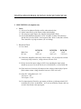
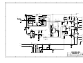
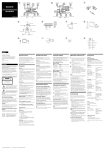
Power Amp
The power amplifier is a push pull single supply amplifier driven by a class A transformer coupled
front end. The drive is provided by HEXFETs (RF9520/9530) into NPN BJTs (TIP35C). When
replacing the FETs it is recommended that you replace both FETs. The matching of these FETs
determines the balancing of the emitter currents in the output devices. For optimum performance the
emitter currents in each side should match to within 30% of each other.
Bias Setup
The amplifier is set with a bais setting of 1mV measured across the emitter resitors.
Bias is set using the trimpots located on the power pcbs on each side of the amplifier.
Turning the trimpots cw increases the bias.
If the HEXFETs have been replaced the resistor in series with the pot may need to be changed. Use a
lower value resistor if the bias cannot be turned off or a higher value if the bias cannot be turn on.
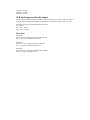
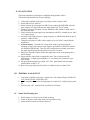
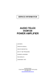
AC Power Inlet
The operating voltage is 230/240 VAC @ 50 Hz. The 3 pin IEC power inlet is located on the bottom
left of the rear panel and accepts a standard mains power lead fitted with an IEC connector. Before
plugging in a power lead, please check the rear panel of the amplifier to ensure that the voltage switch
is set correctly for your part of the world.
The inlet is equipped with an in-built AC fuse containing the rated fuse and a spare.
24 Volt DC Power Inlet
The DCM series feature optional 24VDC power to run off a battery back-up if required. This is
connected via the rear binding posts. The front panel Power Switch will not switch DC power ‘on’ or
‘off’ in DC operation. In this mode the amplifier is always ‘on’.
The trickle charge resistor across the diode is a 47ohm/5watt wire wound resistor. The maximum
trickle current is 300mA supplied from internal 35V rails.
230V/240V Slide Switch
The operating voltage of the amplifier is user selectable between 230V and 240V via a slide switch
located on the center of the rear panel. This switch should be set to match the AC voltage of your
country. The mains transformer is wound with a 230V winding plus a 10V winding internally
connected.
Speaker Output Terminal Strip
The screw terminals located on the top left of the rear panel allow access to the direct speaker outputs
of the amplifier. Reading from left to right the terminals are:
COM
4
8
Common or “-” for low impedance speaker loads (4 or 8 ohms)
Positive “+” for 4 ohm speaker loads (use with common)
Positive “+” for 8 ohm speaker loads (use with common) DCM120 only
COM
70
100
Common or “-” for 70v or100v speaker loads
Positive “+” for 70v line speaker loads (use with common) DCM120/500 only
Positive “+” for 100v line speaker loads (use with common)
Please ensure that the correct “Common” is used. Low impedance and 70/100v loads can be used
simultaneously but please pay careful attention to the overall speaker load.
Note: The minimum impedance (or maximum load) at 100 volt line should be no less than
DCM120 – 80 ohms
DCM250 – 40 ohms
DCM500 – 20 ohms
XLR Audio Input and Parallel Output
The DCM series includes both male and female 3 pin XLR connectors per channel. While the female is
normally used as the input to the amplifier, both XLR’s are connected in parallel so either will work.
The XLR’s inputs are transformer balanced and wired as:
Pin 1: Shield.
Pin 2: Hot, +, Positive
Pin 3: Cold, -, Negative
Fuse Sizes
(DCM120)
Mains: 230 VAC 4 Amperes Slow Blow HRC 20x5mm
DC: 10 Amperes Slow Blow HRC 20x5mm
(DCM250)
Mains: 230 VAC 6.3 Amperes Slow Blow 20x5mm
DC: 2 x 10 Amperes Slow Blow HRC 3AG
(DCM500)
Mains: 230 VAC 10 Amperes Slow Blow HRC 20x5mm
DC: 2 x 35 Amperes Slow Blow 3AG
TESTING PROCEDURE OF DCM 120/DCM 250/DCM 500
I. PRE-TESTING (of complete sets).
•
Check
1.1 All screw for tightness (Bridge rectifier and transistor bolts)
1.2 Earth Connection for good contact (solder and crimpling)
1.3 This setup has signal input to the Amplifier through male (XLR)
1.4 Check with Multimeter that there is a DC resistance of about 250 Ω between
Pin2 & Pin3 of each of XLR’s. Also between (Pin 1 & Pin 3) and (Pin1 & Pin2).
There should be very high resistance. (IE: no reading).
2. Electrical Check
2.1 Fuse Check:
Mains fuse:
DC fuse:
DCM 120
DCM 250
DCM 500
4AT
10AT (x1)
6.3 AT
10AT (x2)
10 AT
35AT (x2)
2.2 Connect the Amplifier to the setup (Variac voltage = 0V) set all presets on front
board (only) fully clockwise, voltage selector switch to 230V
2.3 Slowly increase the input voltage to 230V, keep watching the input current
should not exceed 0.1A for DCM-120, 0.1A for DCM-250, 0.1A for DCM 500.
2.4 Check and reset if necessary all emitter resistor voltages with the help of preset.
(Each emitter resistor voltage should be between 0.5 mV to 0.8 mV )
2.5 Check DC voltage Main rail = 33V
7815 input = 30V
7815 output = 15.5V
2.6 Give input signal of 500 mV to get outputs as follows (@ 4Ω output load)/ 22V
for DCM 120, 32VAC for DCM250, 44.7VAC for DCM 500. Check 100V O/p
at 100vV line, Remove the input signal
II. FINAL TESTING
(This setup should have signal input to Amplifier through female (XLR)
(The limiter link should be out of circuit initially.)
1. Connect the Amplifier to the setup, set voltage selector switch to 240V
2. Switch ON the set to 240VAC.
3. Slowly increase the input signal (of 1kHz) keep watching the 24dB LED, it should
glow at approx 9V output. Increase the input signal to get 70VAC output.
4. Check Dc voltage of all emitter resistors, Minimum value should be within 30% of
the maximum value.
5. Slowly increase the input signal, keep watching the 0db LED, it should glow at 100V
± 5V output voltage.
6. Set 100V 1kHz as 0db reference. Change frequency to 10kHz check dB level drop. It
should be 2.5dB ± 0.5dB.
7. Change the frequency to 1kHz, reduce signal level to get 10VAC output. Half the
output load.
8. Overload setting: - Check the DC voltage at the emitter resistors having the
maximum voltage value. Increase input signal to get 820mV for DCM 120, 425mV
(for DCM250 & DCM 500). Turn preset (P2) anticlockwise such that it just mutes
the output signal and signal returns back slowly after 2 seconds.
9. Reduce the signal & re check whether the signal mutes at the corresponding above
stated voltages.
10. Again make the output load to original full value. Turn volume preset fully
anticlockwise, set input signal strength to 1V, set volume preset clockwise to get
100V output.
11. Set input signal strength to get output 110V VAC. Insert limiter link, the signal
should reduce to 100V ± 5V.
12. Remove the input signal and check noise. It should measure less than 25mV.
III. THERMAL & SOAK TEST
1. Connect the Amplifier to the setup : Output load = 4Ω Output Voltage: (DCM 120):
14V. (DCM 250):20V. (DCM 500): 40V
2. Set the Amplifier thermal cut off temperature at around 105°C with the help of preset
P4.
3. Leave the unit “ON” (with lid fixed, if possible) for 24 hours.
IV. Sound Test/Listening test.
1. Switch On the set. Check for any switch on thump.
2. Connect CD player to the input, listen for irregularities if any.
3. Switch off the set check for switch off noises.
1
2
3
4
5
6
8
7
X1
1
2
3
D
D
4
5
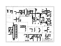
D1
40A
BATTERY
F2
35A
+
24V
-
F1
10A
F3
35A
T1
+35VDC
BR1
C1
240AC IN
C2
C3
C4
10000U
C
C
S1
X8
1
2
3
X6
X5
X4
X1
R2
47R
X3
X2
X7
1
2
3
BR3
V1
BC639
C8
C5
4u7
0.15u
R3
100R
C6
4u7
RY1
R1
4K7
C7
10u
D3
12V
B
B
D2
PCB6203
A
A
Title
Size
A3
Date:
File:
1
2
3
4
5
6
DCM500 POWER SUPPLY
CD6203-1
B
Number
28-Aug-2002
Sheet of
C:\Protel Files\CDTRAX\CD6203-1.DDB Drawn By:
7
Revision
1
2
RS
8
1
2
3
4
5
6
7
8
X1
1
2
3
D
D
4
5
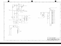
D1
40A
BATTERY
F2
35A
+
24V
-
F1
10A
F3
35A
T1
+35VDC
BR1
C1
240AC IN
C2
C3
C4
10000U
S1
C
X8
1
2
3
X6
X5
X4
C
X1
X3
R2
47R
X2
X7
1
2
3
BR3
V1
BC639
C8
R3
100R
C5
4u7
0.15u
C6
4u7
RY1
R1
4K7
C7
10u
D3
12V
B
B
D2
PCB6203
A
A
Title
Size
A3
Date:
File:
1
2
3
4
5
6
DCM500 POWER SUPPLY
CD6203-1
C
Number
6-May-2003
C:\DCM Manuals\CD6203-1.DDB
7
Revision
Sheet of
Drawn By:
1
2
SBG
8
1
2
3
4
5
6
7
8
D
D
16V
1
16
IC3A
NE570
2
2u2
3
C10
C5
2u2
R35
33K
100K
R15
C8
100P
5
12
6
11
7
10
8
9
4
C
C13
47P
C12
2u2
C17
2u2
R25
10K
LK2
X1/3
R24
10k
R20
10k
100K
LM358
V3
R30
2K2
C22
47u
7
8
LK4
IC2A
C3
10u
D1
C23
R8
100R
100P
R21 10k
R31
2K2
6
2
X4/5
R12
100R
LK3
R10
1K
LK5
4
R32
56K
R4
10K
C2
2u2
IC4A
2u2
C21
C24
.1u
V2
BC639
R11
390R
C20
2u2
X2/2
R53
1K
P1
2K
16V
X2/1
R7
100R
R18
1K
BC546
IC5
NE555
1
C
X5
R9
5K6
R29
1M
B
R3
10K
C6
2u2
R19
D2
D9
V1
BC639
C9
.47u
C14
47P
R5
680R
X1/2
C1
2u2
D3
5
X1/1
R1
68K
IC4B
C19
47u
3
T1A
R23
39K
IC2B
R17
47K
C33
4u7
14
R27
X3/1
2M2 R28
15
100K
R16 2M2
47K
P2
16VDC
13
C26
4u7
X3/3
LM833
D8
T1B
68K
R2
10k
R22
LK7
X3/5
B
R6
680R
D7
A
HI TEMP
X3/4
X3/2
R14
22R
X4/2
IC1
7815
16VDC
C16
100u
LK1
X4/6
GND
C4
2u2
D4
C7
100u
C27
4u7
D5
R34
22K
D6
8V2
C15
A
R33
2K2
C25
2u2
R13
22K
10R
R26
8V2
C18
4u7
A
2u2
Title
Size
Number
A3
Date:
File:
1
2
3
4
5
6
DCM DRIVER
CD6200-1
11-Sep-2003
Sheet of
C:\Protel Files\CDTRAX\CD6200-1.DDB Drawn By:
7
A
Revision
1
2
RS
8
1
2
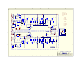
Microprocessor
3
4
5
6
8
7
Mute/Limiter/Drive
VCC
13
VCC
D
2
3
4
VDD
VSS
GP5
GP0
GP4
GP1
GP3
GP2
1
8
R16 2M2
7
2u2
C10
X3/1
6
C5
2u2
47K
P2
5
R35
33K
100K
R15
I/O
Desc
7.
GP0-OUT = 1/2VCC CON
6.
GP1-OUT = FAN CON
5.
GP2-OUT = PRTCT/MUTE
4.
GP3-IN
= I LIMIT
3.
GP4-IN
= FAN SENSE
2.
GP5-IN
= THRML SENS
3
14
5
12
6
11
7
10
8
9
VCC
R25
10K
R30
10K
V5
BC546
R19
2u2
100K
X1/3
R20
10k
VU Display
R3
10K
IC4B
LM833-B
R7
100R
AGND
R9
5K6
X5
IC2A
LM358
V8
BC556
C19
47u
C23
100P
R12
100R
C3
10u
D2
R10
1K
R8
100R
R21
39k
LK4
0R
C2
2u2
R4
10K
V2
BC639
R11
390R
VCC
IC4A
LM833-A
LK6
0R
C
X3/2
IC2B
LM358
Battery Indicator
X2/1
(N/C)
C6
2u2
R24
10k
D1
0R
LK3
R17
47K
V1
BC639
C9
.47u
C12
D
X1/1
R5
680R
X1/2
C1
2u2
IC6/P5
C
T1A
R1
68K
LK2
VCC
R26
10K
C33
4u7
R23
10K
C17
2u2
C14
47P
C13
47P
R29
10K
2M2 R27
15
4
Pin
C26
4u7
16
IC3A
SA571
2
R28
1
100K
IC6
PIC12C509
VDD
C8
100P
X3/3
68K
R2
10k
R22
T1B
X3/5
R6
680R
X3/4
AGND
IC7
LN3915
3
10
5
C35
4u7
R48
1K
11
6
B
12
7
R49
10K
X1/5
9
13
D17
D18
D19
D20
VCC
D16
+3DB
0
C32
4u7
R44
1K
V4
BC556
Protect/On Indicator
X1/4
-3
D27
IC6/P5
Fan Control
X2/5
X2/6
(N/C)
VCC
R55
10K
VDD
X4/4
D13
R51
1K
R56
10K
IC6/P2
D31
V6
BC546
IC6/P6
R46
1K2
14
D21
-9
R45
2K7
15
D22
-12
16
D23
-15
X2/4
*
*
Current Limit
R14
22R
X2/3
IC1
7815
IC5
7805
16VDC
VCC
VDD
17
D24
-18
18
D25
-21
1
D26
R32
470K
X4/6
GND
C4
D4
C7
100u
VDD
R33
22K
IC6/P7
4
R36
10K
V7
BC546
V3
BC546
AGND
8V2
R34
22K
Title
Number
A3
Date:
File:
2
3
4
5
6
X4/5
P1
2K
A
C18
4u7
Size
1
X2/2
R53
1K
IC6/P4
AGND
2
R31
10k
C11
22u
R13
10K
C16
100u
-25
C15
100u
C20
47u
2u2
A
V9
BC556
R18
1K
VDD
X4/2
R41=15K=DCM120/500
R41=12K=DCM 250
X4/3
POWER
PROTECT
Power
R41
FAN CONTROL
IC6/P3
X4/1
8
B
P4
10K
D10
MAINS
FAIL
-6
Thermal Sense
R42
1K
R43
470R
DCM DRIVER
CD6200-1
7-Apr-2005
Sheet of
C:\Protel Files\CDTRAX\CD6200-12.DDBDrawn By:
7
D
Revision
1
1
SBG
8
1
2
3
4
5
6
8
7
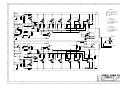
DCM500
D
V10-V15 = TIP35C
X1
1
500R
2
3
R36A
220R
R1A
R25,R27,R29,R31,R33,
R35 = 0.22R
+35V
220R
R2A
D
R24,R26,R28,R30,R32,
R34 =2K2
V1A
R3A
220R
11 X TIP35C
PCB6201
V4A
X2
1
R4A
1K
D1A
R5A
150R
R6A
150R
V5A
V6A
V7A
V8A
V9A
D2A
X1 TO PCB6136
R38A
47k
X2 TO PCB6200 X3
2
X3 TO PCB6200 X4
3
V2A
4
R12A
2K2
R13A
R22
R14A
2K2
R15A
R22
R16A
2K2
R17A
R22
R18A
2K2
R19A
R22
R20A
2K2
R21A
R22
R22A
2K2
X4 TO FAN
R23A
R22
PCB6202
5
R40
1K
R8A
470R
R41A
100D
C
X3
1
2
R39A
10R
35V
R10A
1K
X1 TP PCB6203
C1A
820P
X2 TO PCB6200 X1
R7A
10R
IC1A
78L05
X3 TO PCB6200 X2
R9A
1K
X4 TO FAN
R11A
4K7
X3
4
V3A
BC556
5
3
X4
1
FAN
2
D4
24V
6
T2
100VAC
PCB6202
D3A
70AC
5
5
D3B
4
3
R10B
1K
R40B
1K
IC1B
78L05
2
1
R39B
4K7
R11B
4K7
5
2
4
1
FAN
3
R41
80D
BC556
V3B
R9B
1K
R8B
470R
X1
C
V16
TIP41C
COM
X4
4 OHM
X3
5
4
R7B
10R
C1B
820P
3
B
B
2
R5B
150R
1
R6B
150R
V2B
R12B
2K2
R13B
R22
R14B
2K2
R15B
R22
R16B
2K2
R17B
R22
R18B
2K2
R19B
R22
R20B
2K2
R21B
R22
R22B
2K2
R23B
R22
R42B
10R
X2
V4B
V5B
V6B
V8B
V7B
V9B
D2B
R38B
R4B
1K
2
D1B
47k
11 X TIP35C
V1B
1
X3
R1B
220R
R37
0R
R3B
220R
R36B
500R
PCB6201
R2B
220R
+35V
A
A
Title
Size
A3
Date:
File:
1
2
3
4
5
6
DCM500 POWER PCB
CD6201-1
Number
28-Aug-2002
Sheet of
C:\Protel Files\CDTRAX\CD6201-1.DDB Drawn By:
7
Revision
2
RS
1
8
1
2
3
4
5
6
8
7
DCM500
D
V10-V15 = TIP35C
X1
1
500R
2
R36A
3
220R
R1A
R25,R27,R29,R31,R33,
R35 = 0.22R
R2A
11 X TIP35C
V4A
R4A
1K
D1A
R5A
150R
R6A
150R
V5A
V6A
V7A
V8A
V9A
R38A
47k
PCB6201
D2A
X1 TO PCB6136
X2 TO PCB6200 X3
2
3
4
X3 TO PCB6200 X4
V2A
R12A
2K2
R13A
R22
R14A
2K2
R15A
R22
R16A
2K2
R17A
R22
R18A
2K2
R19A
R22
R20A
2K2
R21A
R22
R22A
2K2
X4 TO FAN
R23A
R22
5
PCB6202
R40
0R
C
X3
1
2
R8A
470R
R41A
10k NTC
R39A
10R
35V
R10A
1K
X1 TP PCB6203
C1A
820P
R7A
10R
IC1A
78L05
X2 TO PCB6200 X1
X3 TO PCB6200 X2
R9A
1K
R11A
4K7
X3
4
V3A
BC556
5
X4 TO FAN
V16
TIP41C
3
X4
1
FAN
2
D4
24V
6
5
D3B
3
R10B
1K
2
1
70AC
2
4
1
R39B
4K7
R11B
4K7
FAN
COM
X4
4 OHM
X3
R7B
10R
C1B
820P
3
5
3
R41
NOT USED
BC556
V3B
R9B
1K
5
4
R40B
1K
IC1B
78L05
R8B
470R
X1
B
2
R5B
150R
1
R6B
150R
V2B
R12B
2K2
R13B
R22
R14B
2K2
R15B
R22
R16B
2K2
R17B
R22
R18B
2K2
R19B
R22
R20B
2K2
R21B
R22
R22B
2K2
R23B
R22
R42B
10R
X2
V4B
R4B
1K
2
V5B
V6B
47k
V8B
V9B
D2B
11 X TIP35C
V1B
R1B
220R
R37
0R
V7B
R38B
D1B
1
X3
T2
100VAC
5
4
C
PCB6202
D3A
B
D
R24,R26,R28,R30,R32,
R34 =2K2
V1A
R3A
220R
X2
1
+35V
220R
R3B
220R
R36B
500R
PCB6201
R2B
220R
+35V
A
A
Title
Size
A3
Date:
File:
1
2
3
4
5
6
DCM500 POWER PCB
C
CD6201-1
Number
8-May-2003
Sheet of
C:\DCM Manuals\CD6201-12.DDB Drawn By:
7
Revision
1
8
2
SBG
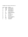
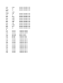
DCM500 Power Supply Components List
Designator
BR1
BR3
C1
C2
C3
C4
C5
C6
C7
C8
D1
D2
D3
F1
F2
F3
R1
R2
R3
RY1
S1
T1
V1
Part Type
KBPC3504
KBPC3504
15000uF
15000uF
15000uF
15000uF
4u7
4u7
10u
0.15u
40A
1N4007
12V
***
35A
35A
4K7
47R
100R
Relay
Switch
BC639
Description
Bridge recitfier 600V/35A
Bridge recitfier 600V/35A
Electrolytic Capacitor 50V
Electrolytic Capacitor 50V
Electrolytic Capacitor 50V
Electrolytic Capacitor 50V
Electrolytic Capacitor 50V
Electrolytic Capacitor 50V
Electrolytic Capacitor 50V
Metalised Poly Capacitor 275V
Stud Mount Rectifier Diode 40A
Rectifier Diode
Zener diode 1W 12V
Fuse, refer user manual
Fuse, 35A 3AG
Fuse, 35A 3AG
Resistor, metal film .5W
PW5 Wire Wound resistor 5W
PW10 Wire wound resistor 10w
Relay 12V 16A SPDT
Rocker Switch DPST
Power transformer
Transistor TO92
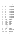
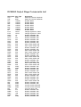
DCM Series Drive Stage Component List
Designator
C1
C10
C11
C12
C13
C14
C15
C16
C17
C18
C19
C2
C20
C23
C26
C3
C32
C33
C35
C4
C5
C6
C7
C8
C9
D1
D10
D13
D16
D17
D18
D19
D2
D20
D21
D22
D23
D24
D25
D26
D27
D31
D4
IC1
IC2A
IC2B
IC3
IC4A
IC4B
IC5
IC6
Part Type
2u2
2u2
22u
2u2
47P
47P
100u
100u
2u2
4u7
47u
2u2
47u
100P
4u7
10u
4u7
4u7
4u7
2u2
2u2
2u2
100u
100P
.47u
1N4148
L-LED(red)
L-LED(red)
1N4148
L-LED(red)
L-LED(red)
L-LED(grn)
1N4148
L-LED(grn)
L-LED(grn)
L-LED(grn)
L-LED(grn)
L-LED(grn)
L-LED(grn)
L-LED(grn)
L-LED(grn)
1N4148
1N4007
7815
LM358
LM358
SA571
LM833-A
LM833-B
7805
PIC12C509
Description
Electrolytic Capacitor 35V
Electrolytic Capacitor 35V
Electrolytic Capacitor 35V
Electrolytic Capacitor 35V
Multi layer ceramic capacitor
Multi layer ceramic capacitor
Electrolytic Capacitor 16V
Electrolytic Capacitor 16V
Electrolytic Capacitor 35V
Electrolytic Capacitor 35V
Electrolytic Capacitor 35V
Electrolytic Capacitor 35V
Electrolytic Capacitor 35V
Multi layer ceramic capacitor
Electrolytic Capacitor 35V
Electrolytic Capacitor 35V
Electrolytic Capacitor 35V
Electrolytic Capacitor 35V
Electrolytic Capacitor 35V
Electrolytic Capacitor 35V
Electrolytic Capacitor 35V
Electrolytic Capacitor 35V
Electrolytic Capacitor 16V
Multi layer ceramic capacitor
Metalised Poly Capacitor 63V
Rectifier Diode
LED 3.0mm
LED 3.0mm
Rectifier Diode
LED 3.0mm
LED 3.0mm
LED 3.0mm
Rectifier Diode
LED 3.0mm
LED 3.0mm
LED 3.0mm
LED 3.0mm
LED 3.0mm
LED 3.0mm
LED 3.0mm
LED 3.0mm
Rectifier Diode
Rectifier Diode
Voltage regulator I.C TO220
Comparator, dual IC DIP
Comparator, dual IC DIP
Compander IC DIP
Dual op-amp IC DIP
Dual op-amp IC DIP
Regulator IC TO92
Programmable IC DIP
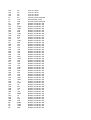
LK2
LK3
LK4
LK6
P1
P2
P4
R1
R10
R11
R12
R13
R14
R15
R16
R17
R18
R19
R2
R20
R21
R22
R23
R24
R25
R26
R27
R28
R29
R3
R30
R31
R32
R33
R34
R35
R36
R4
R41
R41
R42
R43
R44
R45
R46
R48
R49
R5
R51
R53
R55
R56
R6
R7
R8
R9
0R
0R
0R
0R
2K
47K
10K
68K
1K
390R
100R
10K
22R
100K
2M2
47K
1K
100K
68K
10k
39k
10k
10K
10k
10K
10K
2M2
100K
10K
10K
10K
10k
470K
22K
22K
33K
10K
10K
15K*
12K**
1K
470R
1K
2K7
1K2
1K
10K
680R
1K
1K
10K
10K
680R
100R
100R
5K6
Link, zero ohms
Link, zero ohms
Link, zero ohms
Link, zero ohms
Cermet, preset Horizontal
Potentiometer 16mm
Cermet, preset Horizontal
Resistor, metal film .5W
Resistor, metal film .5W
Resistor, metal film .5W
Resistor, metal film .5W
Resistor, metal film .5W
Resistor, metal film .5W
Resistor, metal film .5W
Resistor, metal film .5W
Resistor, metal film .5W
Resistor, metal film .5W
Resistor, metal film .5W
Resistor, metal film .5W
Resistor, metal film .5W
Resistor, metal film .5W
Resistor, metal film .5W
Resistor, metal film .5W
Resistor, metal film .5W
Resistor, metal film .5W
Resistor, metal film .5W
Resistor, metal film .5W
Resistor, metal film .5W
Resistor, metal film .5W
Resistor, metal film .5W
Resistor, metal film .5W
Resistor, metal film .5W
Resistor, metal film .5W
Resistor, metal film .5W
Resistor, metal film .5W
Resistor, metal film .5W
Resistor, metal film .5W
Resistor, metal film .5W
Resistor, metal film .5W
Resistor, metal film .5W
Resistor, metal film .5W
Resistor, metal film .5W
Resistor, metal film .5W
Resistor, metal film .5W
Resistor, metal film .5W
Resistor, metal film .5W
Resistor, metal film .5W
Resistor, metal film .5W
Resistor, metal film .5W
Resistor, metal film .5W
Resistor, metal film .5W
Resistor, metal film .5W
Resistor, metal film .5W
Resistor, metal film .5W
Resistor, metal film .5W
Resistor, metal film .5W
T1A
T1B
V1
V2
V3
V4
V5
V6
V7
V8
V9
RF2285A
RF2285B
BC639
BC639
BC546
BC556
BC546
BC546
BC546
BC556
BC556
Please note
Please note
Driver Transformer
Driver Transformer
Transistor TO92
Transistor TO92
Transistor TO92
Transistor TO92
Transistor TO92
Transistor TO92
Transistor TO92
Transistor TO92
Transistor TO92
* DCM120-DCM500
** DCM250
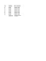
DCM500 Output Stage Components List
Designator
C1A
C1B
D1A
D1B
D2A
D2B
D3A
D3B
D4
IC1A
IC1B
R10A
R10B
R11A
R11B
R12A
R12B
R13A
R13B
R14A
R14B
R15A
R15B
R16A
R16B
R17A
R17B
R18A
R18B
R19A
R19B
R1A
R1B
R20A
R20B
R21A
R21B
R22A
R22B
R23A
R23B
R2A
R2B
R36A
R36B
R37
R38A
R38B
R39A
R39B
R3A
Part Type
820P
820P
1N4007
1N4007
1N4007
1N4007
1N4007
1N4007
1N4007
78L05
78L05
1K
1K
4K7
4K7
2K2
2K2
R22
R22
2K2
2K2
R22
R22
2K2
2K2
R22
R22
2K2
2K2
R22
R22
220R
220R
2K2
2K2
R22
R22
2K2
2K2
R22
R22
220R
220R
500R
500R
0R
47k
47k
10R
4K7
220R
Description
Multi layer Ceramic Capacitor
Multi layer Ceramic Capacitor
Rectifier Diode
Rectifier Diode
Rectifier Diode
Rectifier Diode
Rectifier Diode
Rectifier Diode
Rectifier Diode
Voltage regulator IC TO92
Voltage regulator IC TO92
Resistor, Metalfilm .5W
Resistor, Metalfilm .5W
Resistor, Metalfilm .5W
Resistor, Metalfilm .5W
Resistor, Metalfilm .5W
Resistor, Metalfilm .5W
Wire wound resistor 5W
Wire wound resistor 5W
Resistor, Metalfilm .5W
Resistor, Metalfilm .5W
Wire wound resistor 5W
Wire wound resistor 5W
Resistor, Metalfilm .5W
Resistor, Metalfilm .5W
Wire wound resistor 5W
Wire wound resistor 5W
Resistor, Metalfilm .5W
Resistor, Metalfilm .5W
Wire wound resistor 5W
Wire wound resistor 5W
Resistor, Metalfilm .5W
Resistor, Metalfilm .5W
Resistor, Metalfilm .5W
Resistor, Metalfilm .5W
Wire wound resistor 5W
Wire wound resistor 5W
Resistor, Metalfilm .5W
Resistor, Metalfilm .5W
Resistor, Metalfilm .5W
Wire wound resistor 5W
Resistor, Metalfilm .5W
Resistor, Metalfilm .5W
Cermet, preset horizontal
Cermet, preset horizontal
Link, zero ohms .5W
Resistor, Metalfilm .5W
Resistor, Metalfilm .5W
Resistor, Metalfilm .5W
Resistor, Metalfilm .5W
Resistor, Metalfilm .5W
R3B
R40
R40B
R41
R41A
R42B
R4A
R4B
R5A
R5B
R6A
R6B
R7A
R7B
R8A
R8B
R9A
R9B
T2
V16
V1A
V1B
V2A
V2B
V3A
V3B
V4A
V4B
V5A
V5B
V6A
V6B
V7A
V7B
V8A
V8B
V9A
V9B
220R
1K
1K
Resistor, Metalfilm .5W
Resistor, Metalfilm .5W
Resistor, Metalfilm .5W
100D
10R
1K
1K
150R
150R
150R
150R
10R
10R
470R
470R
1K
1K
Resistor, Metalfilm .5W
Resistor, Metalfilm .5W
Resistor, Metalfilm .5W
Resistor, Metalfilm .5W
Resistor, Metalfilm .5W
Resistor, Metalfilm .5W
Resistor, Metalfilm .5W
Resistor, Metalfilm .5W
Resistor, Metalfilm .5W
Resistor, Metalfilm .5W
Resistor, Metalfilm .5W
Resistor, Metalfilm .5W
Resistor, Metalfilm .5W
TIP41C
TIP41C
TIP41C
IRF9520
IRF9520
BC556
BC556
TIP35C
TIP35C
TIP35C
TIP35C
TIP35C
TIP35C
TIP35C
TIP35C
TIP35C
TIP35C
TIP35C
TIP35C
Transistor TO220
Transistor TO220
Transistor TO220
Mosfet, hexfet
Mosfet, hexfet
Transistor T092
Transistor T092
Transistor TOP-3
Transistor TOP-3
Transistor TOP-3
Transistor TOP-3
Transistor TOP-3
Transistor TOP-3
Transistor TOP-3
Transistor TOP-3
Transistor TOP-3
Transistor TOP-3
Transistor TOP-3
Transistor TOP-3