1
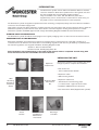
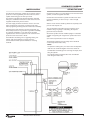
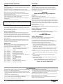
WORCESTER GREENSTORE
Indirect Unvented Cylinder with Solar Coil
FOR USE WITH WORCESTER GREENSTORE SYSTEM HEATPUMP ONLY
GB/IE
WORCESTER GREENSTORE 180 CYLINDER
SOLAR COMPATIBLE
WORCESTER GREENSTORE 280 CYLINDER
SOLAR COMPATIBLE
INTRODUCTION
The Greenstore cylinder shell is made from Stainless Steel for excellent
corrosion resistance. Greenstore cylinders have a strong steel case and
are well insulated with environmentally friendly insulation.
They are available in two sizes, 180 and 280 litres, both with a
supplementary coil for use with solar or other fuels. For other fuels, you
may need to source a dual thermostat for control purposes.
The Greenstore cylinder is supplied complete with all the necessary, pre-adjusted, safety and control devices needed to
connect to the cold water supply mains.
High quality controls have been selected to combine high flow rate performance with minimum pressure drop to allow the
Greenstore cylinder to perform well in areas, where there is a minimum dynamic working mains pressure of 1.5 bar.
Greenstore cylinders are KIWA approved and comply with Building Regulations KIWA sections G3 and Part L1.
STORAGE PRIOR TO INSTALLATION
The Greenstore cylinder should be stored upright in the original packaging and in an area free from excessive moisture.
IMPORTANT NOTE TO THE INSTALLER
Read these installation and maintenance instructions carefully before commencing work. Unvented cylinders are a
controlled service as defined in the latest edition of the building regulations and must only be fitted by a qualified person.
The relevant regulations are: England and Wales - Building Regulations G3,
Scotland - Technical standard P3,
Northern Ireland - Building Regulation P5
After installation, the benchmark log, in the back of this manual, must be completed and left along with
these instructions with the householder for future reference.
UNPACKING THE UNIT
Expansion
Vessel
Expansion
Vessel Hose
Greenstore cylinders come complete with all the
fittings required to complete the installation:
• Inlet Control set
• 15mm / 22mm Acetal Tundish
• Expansion vessel
• Wall mounting bracket
Wall
Mounting
Bracket for
Expansion
Vessel
High Flow Rate
Inlet Control
Set
• Expansion vessel hose
• Thermostat for second energy input.
(1 x manual reset - high limit stat for solar)
• Installation & Maintenance Instructions
• Hot water sensor GT3 (Supplied with cylinder)
Acetal
Tundish
2
INTRODUCTION
Installation &
Maintenance
Instructions
Solar High
Limit Stat
Worcester Bosch Greenstore
SCHEMATIC DIAGRAM
WATER SUPPLY
The Worcester Greenstore cylinder has an optimum working
pressure of 3 bar (regulated by the inlet control set) and is
capable of delivering upto 50 litres per minute.
The maximum possible water demand should be assessed
taking into consideration that both hot and cold services are
supplied simultaneously from the mains.
The water supply should be checked to ensure it can meet
these requirements. If necessary consult the local water
authority regarding the likely pressure and flow rate availability.
If measuring the water pressure note that a high static (no
flow) mains pressure is no guarantee of good flow availability.
In a domestic installation 1.5 bar and 25 l/m should be
regarded as the minimum requirement. The maximum mains
pressure for the inlet control is 16 bar.
Consideration should be given to upgrading existing 1/2”
(15mm) cold mains pipework to a larger size if the
recommended minimum pressure/flowrate is not being
achieved.
SITING THE UNIT
Outlets that are above or at some distance from the Greenstore
cylinder, can still be supplied with water.
Outlets above the Greenstore cylinder will reduce the outlet
pressure available by 0.1 bar for every 1 metre of height
difference.
Site the unit to minimise “dead leg” distances especially to the
point of most frequent use.
The unit should be protected from frost. Particular care is
needed if siting in a garage or outbuilding. All exposed
pipework must be insulated.
Greenstore cylinders must be installed upright on a flat base
capable of supporting the weight of the cylinder when full of
water
(see technical specification section for weights).
The discharge pipework from the safety valves should fall
continuously and terminate safely.
Notes:
The pressure reducing valve, non return valve and expansion
relief valve are combined together in the inlet control set.
Consideration should be given for servicing and repair, when
siting the cylinder.
The cylinder position should be taken into consideration
when siting the Heat Pump.
Worcester Bosch Greenstore
3
GENERAL INSTALLATION
COLD MAINS PIPEWORK
HOT WATER PIPEWORK
Run the cold main through the building to where the
Greenstore cylinder is to be installed. Take care not to run the cold
pipe near hot water or heating pipe work to minimize heat pick up.
Identify the cold water supply pipe and fit an isolating valve (not
supplied)
Run the first part of the hot water distribution pipework in 22mm.
This can be reduced to 15mm and 10mm as appropriate for the
type of tap etc. Your aim should be to reduce the volume of the hot
draw-off pipework to a practical minimum so that the time taken for
the hot water is as quick as possible.
A 22mm BS1010 stopcock can typically be used but a 22mm
quarter turn full bore valve is preferred as it does not restrict the
flow as much. Do not use “screwdriver slot” or similar valves.
Do not use monobloc mixer taps or showers if the balanced cold
connection is not used. The unit will back pressurize the cylinder
and result in discharge.
Position the inlet control just ABOVE the Temperature & Pressure
Relief Valve (TPRV) mounted on the top of the cylinder. This
ensures that the cylinder does not have to be drained down in
order to service the inlet control set.
Check that the arrow points in the direction of the water flow.
Mount the expansion vessel in a suitable position on the wall using
the bracket provided. Use the hose to connect to the inlet control
group.
Ensure that the top of the vessel is accessible for servicing.
BALANCED COLD CONNECTION
Where there are showers, bidets or monobloc taps in the
installation then a balanced cold supply is necessary.
There is a 22mm balanced connection on the inlet control set.
Another method is to split the inlet control set on to two parts.
Site the pressure reducing valve immediately after the incoming
cold mains stopcock (typically under the kitchen sink.) All outlets in
the house will be at 3 bar and thus automatically balanced.
The expansion relief valve section must still be mounted just above
the TPRV on the cylinder. A 3/4”F-22mm compression adaptor
will be needed (not supplied)
4
GENERAL INSTALLATION
PRIMARY COIL CONNECTIONS
Connect the primary connections (Indirect only) using the
compression fittings provided for connection to the Worcester
Heat Pump only.
It is preferred that the primary circuit is a sealed system with a
maximum pressure of 2.5 bar. An additional expansion vessel and
safety valve would be required in this case.
The supplementary coil is for use with Worcester Solar Systems
exclusively that are equipped with Worcester solar controls.
Please refer to the installation manuals, Greenstore System
Installation manual and Worcester Greenskies Solar literature:
NOTE:
The relief valve connection should not be used for any
other purposes.
Worcester Bosch Grrenstore
DISCHARGE ARRANGEMENT
Detailed discharge pipe installation requirement
The discharge pipework must be routed in accordance with part G3 of schedule 1 of the Building Regulations
The tundish should be vertical, located in the same space as the unvented hot water cylinder and be as close as possible
and within 500mm of the safety device e.g. the temperature relief valve.
The discharge pipe from the Tundish should be:
• made of metal
• at least one pipe size larger than the nominal outlet size of the safety device (larger sizes my be required if the equivalent hydraulic resistance exceeds that of a straight pipe 9 metres long - refer to BS6700)
• terminate in a safe place where there is no risk to persons in the vicinity of the discharge and positioned safely from
electrical devices
• have a vertical section of pipe at least 300 mm long below the Tundish before any elbows or bends in the pipework
installed with a continuous fall
• visible at both the tundish and the final point of discharge or where this is not possible or practically difficult there
should be clear visibility at one or the other of these locations.
�������������������������������
�������������������������������
����������������������
����������������
�������������
�������������������������������
������������������������������
Valve outlet size
G1/2
<G3>/4
G1
Size of discharge
pipework D1
Size of discharge
pipework D2
15mm
22mm
28mm
Worcester Bosch Greenstore
Maximum length of
straight pipe (no
bends or elbows)
Deduct the figure
below from the maximum length for each
bend or elbow in the
discharge pipe
22mm
up to 9m
0.8m
28mm
up to 18m
1.0m
35mm
up to 27m
1.4m
28mm
up to 9m
1.0m
35mm
up to 18m
1.4m
42mm
up to 27m
1.7m
35mm
up to 9m
1.4m
42mm
up to 18m
1.7m
54mm
up to 27m
2.3m
DISCHARGE ARRANGEMENT
5
COMMISSIONING SERVICING
SERVICING
FILLING
GENERAL
It is important that the inner cylinder is pressurized first, followed
by the primary circuit.
Check the pressure in the DHW expansion vessel is 3 bar
(44PSI), i.e the same as the setting of the pressure reducing valve.
Servicing should only be carried out by competent installers
and any spare parts used must be purchased from Worcester.
Before filling, open the hot tap furthest away from the
Greenstore cylinder to let air out. Open the cold main isolation
valve and allow the unit to fill.
When water flows from the tap, allow it to run for a short while
to flush through any dirt, swarf or flux residue.
Close the tap and open every other hot tap in turn to purge all
remaining air.
The primary circuit can now be filled.
PRIMARY CIRCUIT - INDIRECT UNITS
Consult the Worcester Bosch commissioning instructions and fill
the primary circuit.
STORAGE TEMPERATURE
In many applications the guidance on Legionella control and safe
water delivery temperatures will require storing the water at 6065°C, distributing at 50-55°C and using thermostatic mixing valves
to control the final temperature.
SAFETY VALVE CHECKS
In order to check correct operation of both the expansion and
temperature/pressure relief valves, fully open them allowing as
much water as possible to flow through the tundish. Check that the
discharge pipework is free from debris and is carrying the water
away, to waste, efficiently. Release the valves and check that they
reseat properly.
During heat-up of the cylinder there should have been no sign
of water discharge from either the expansion relief valve or the
temperature / pressure relief valve.
SPARE PARTS
Worcester carry the full range of spares listed below in stock.
If you order before noon we will dispatch the same day
for delivery the next day to most locations.
8 716 113 407 0 8 716 113 409 0
8 716 113 416 0
8 716 113 418 0
8 716 113 415 0
8 716 113 414 0
8 716 113 439 0
8 716 113 440 0
8 716 113 441 0
8 716 113 442 0
8 716 113 498 0
8 716 113 473 0
8 716 112 318 0
-
Inlet control set (pressure reducing valve,
strainer and expansion relief valve )
Tundish
19 litre Expansion Vessel
24 litre Expansion Vessel
Bracket, Expansion Vessel
Hose, Expansion Vessel ( 3/4” M x 3/4” F )
Allen Key
Olive, Blanking 22mm
Olive, Blanking 15mm
Washer
Solar High Limit Stat
Temperature/Pressure relief valve
Hot water sensor GT3
NEVER bypass any safety devices or operate the unit without
them being fully operational.
WARNING:
WATER DRAINED OFF MAY BE VERY HOT!
DRAINING
Isolate the unit from the cold mains.
Open a hot water tap at the lowest position in the building, to
reduce the pressure.
Remove the mains water inlet connection. Attach a flexible hose to
the connection on top of the cylinder, ensuring the hose reaches to
a level well below the unit (The greater the difference in elevation,
the greater the flow rate and the maximum amount of water drained
from the cylinder).
Disconnect the hot water outlet.
Start the siphon effect, by either sucking or pumping the drain side
of the flexible hose.
Allow the cylinder to drain completely.
FLUSHING THE TANK
To flush the cylinder, follow the procedure for draining. Connect a
hose to the hot water outlet and then flush the system.
WARNING:
POSSIBLE SCALDING!
ANNUAL MAINTENANCE
Greenstore cylinders require an annual service in order to
ensure safe working and optimum performance.
It is essential that the following checks are performed by a
competent installer on an annual basis. This is done at the same
time as the annual heat pump and solar service.
1) Twist the cap of the expansion relief valve on the inlet
control set and allow water to flow for 5 seconds. Release
and make sure it resets correctly. Repeat with the pressure
/ temperature relief valve.
In both cases check that the discharge pipework is carrying the
water away adequately. If not check for blockages etc. and
clear.
2) Check the pressure in the DHW expansion vessel is charged to
3 bar. Turn off the water supply to the unit and open a hot tap
first.
3) Unscrew the head on the inlet control set and clean the
mesh filter within.
4) The benchmark log book, in the back of this manual, must be
updated at each service.
YOUR GUARANTEE MAY BE VOID WITHOUT
PROOF OF ANNUAL SERVICING
THE GUARANTEE
The Greenstore cylinder carries a 2 year guarantee against faulty
materials or manufacture provided that:
• It has been correctly installed as per this document and all the
relevant standards, regulations and codes of practice in force at
the time.
• It has not been modified in any way.
• It has not been misused, tampered with or subjected to neglect
• It has only been used for the storage of potable water.
• It has not been subjected to frost damage.
6
COMMISSIONING AND SERVICING
• The unit has been serviced annually
• The benchmark log book has been filled in after each annual service
• The guarantee provided starts from the date of commissioning
• Building Control notification is required
Please note that invoices for servicing may be requested to prove
that the unit has been serviced annually.
All the components fitted to / or supplied with the Greenstore
cylinder carry a 2 year guarantee.
Worcester Bosch Greenstore
TECHNICAL SPECIFICATION
Worcester Greenstore
180/280 LITRE CYLINDERS WITH SOLAR COIL
Return to
Solar Collector
Temperature/Pressure
Relief Valve
Solar High
Limit Stat
pocket
Primary Heating Return
Domestic Hot
Water Outlet
Flow from
Solar Collector
Primary
Heating
Flow
Air Vent
Sacrificial
Anode
Solar Sensor
and
Solar High
Limit Stat
cable entry
Primary
Tank
Solar
Sensor
pocket
Mains Water
Inlet
GT3 Heat Pump
HW Sensor
cable entry
GT3
Heat Pump
HW Sensor
pocket
Solar Heat
Exchanger
Connecting hot water sensor GT3
Before carrying out any electrical connections, ensure that
the Heat Pump is isolated from the mains supply.
Remove the Heat Pump front cover and route the sensor
cable from the back of the Heat Pump, laying the sensor
cable onto the cable tray. Connect the sensor to terminals
GT3X on the terminal card.
Remove the cylinder front cover. Feed the sensor cable
through the grommet of the right-hand cable entry, on top
of the cylinder. Fully insert the sensor probe into the GT3
sensor pocket, as indicated on the diagram above. Replace
the cylinder front cover.
Worcester Bosch Greenstore
TECHNICAL SPECIFICATIONS
7
SPECIFICATION SUMMARY
This is based on a 9kW Heat Pump input
180 litre cylinder storage capacity
DHW side - 180 Litre
Primary side - 105 Litre
280 litre cylinder storage capacity
DHW side - 280 litre
Primary side - 180 litre
180 litre Cylinder heat up time
From 15oC to 60oC - 144 minutes
280 litre Cylinder heat up time
From 15oC to 60oC - 163 minutes
Reheat time
For 70% volume - 47 minutes
Reheat time
For 70% volume - 53 minutes
Heat loss time
For 60oC to 53.6oC - 24 hours
Heat loss time
For 60oC to 53.6oC - 24 hours
Materials
Shell - Stainless steel, inner - black carbon steel, outer
Coil - 15mm diameter copper
Greenstore cylinder is water tested to a pressure of 13 bar.
Insulation
Fire retardant mineral wool, nominal thickness 50mm.
Casework
Powder coated corrosion proof steel
Anode
Fitted (Aluminium)
Expansion Vessel
19 Litre size with 180 litre model
24 Litre size with 280 litre model
Control Settings
Pressure Reducing Valve
- 3 bar
Expansion Relief Valve
- 6 bar
Pressure and Temperature Relief Valve
- 7 bar / 95°C
Max inlet pressure (PRV)
- 16 bar
Operating pressure (primary side)
- 2.5 bar
Maximum operating pressure (DHW)
- 3.0 bar
Expansion vessel pressure charge
- 3.0 bar
Expansion relief valve setting
- 6.0 bar
PART No.
CAPACITY
HEIGHT
WIDTH
DEPTH
WEIGHT
kg empty
WEIGHT
kg full
7 716 180 017
180 L
1520
600
650
97
387
695
136
596
7 716 180 018
280 L
1700
695
All Dimensions are of the cased unit and are in mm.
Approvals
- KIWA Approved to the Water Regulations
- KIWA Approved to Building Regulations’ G3 & L1
8
Worcester Bosch Greenstore
COMMISSIONING PROCEDURE INFORMATION
ENERGY SOURCE PRIMARY SETTINGS (INDIRECT HEATING ONLY)
IS THE PRIMARY A SEALED OR OPEN VENTED SYSTEM?
SEALED
OPEN
WHAT IS THE ENERGY SOURCE FLOW TEMPERATURE?
ALL MAINS PRESSURED SYSTEMS
WHAT IS INCOMING STATIC COLD WATER PRESSURE AT THE INLET
TO THE PRESSURE REDUCING VALVE?
bar
HAS A STRAINER (IF FITTED) BEEN CLEANED OF INSTALLATION DEBRIS?
YES
NO
HAS A WATER SCALE REDUCER BEEN FITTED?
YES
NO
ARE COMBINED TEMPERATURE/PRESSURE RELIEF VALVE
AND EXPANSION VALVE FITTED AND DISCHARGED TESTED?
YES
NO
IS PRIMARY ENERGY SOURCE CUT-OUT FITTED
(NORMALLY 2 PORT VALVE)?
YES
NO
WHAT TYPE OF SCALE REDUCER HAS BEEN FITTED
UNVENTED SYSTEMS ONLY
WHAT IS THE PRESSURE REDUCING VALVE SETTING (IF FITTED)
bar
WHERE IS OPERATING PRESSURE REDUCING VALVE SITUATED
HAS THE EXPANSION VESSEL OR INTERNAL AIR SPACE BEEN CHECKED
YES
WHAT IS THE HOT WATER TEMPERATURE AT THE NEAREST OUTLET
NO
oC
THERMAL STORES ONLY
WHAT IS THE OPERATING SETTING OF THE PRESSURE REDUCING VALVE (Where fitted)?
bar
WHERE IS THE PRESSURE REDUCING VALVE SITUATED?
WHAT STORE TEMPERATURE IS ACHIEVABLE?
oC
WHAT IS THE MAXIMUM HOT WATER TEMPERATURE?
oC
WHAT IS THE MAXIMUM HOT WATER FLOW RATE AT MAXIMUM TEMPERATURE?
lts/min
ALL PRODUCTS
DOES THE HOT WATER SYSTEM COMPLY WITH
THE APPROPRIATE BUILDING REGULATIONS?
YES
HAS THE SYSTEM BEEN INSTALLED AND COMMISSIONED
IN ACCORDANCE WITH THE MANUFACTURER’S INSTRUCTIONS?
YES
HAVE YOU DEMONSTRATED THE OPERATION OF THE
SYSTEM CONTROLS TO THE CUSTOMER?
YES
HAVE YOU LEFT ALL THE MANUFACTURER’S
LITERATURE WITH THE CUSTOMER?
YES
COMPETENT PERSON’S
SIGNATURE
Worcester Bosch Greenstore
CUSTOMER’S
SIGNATURE
(To comfirm demonstations of equipment and
receipt of appliance instructions)
9
SERVICE INTERVAL RECORD
It is recommended that your heating system is serviced regularly and that your service
engineer completes the appropriate Service Interval Record below.
SERVICE PROVIDER
Before completing the appropriate Service Interval Record below, please ensure
you have carried out the service as described in the manufacturer’s instructions
and in compliance with The Safety Regulations.
Always use the appliance manufacturer’s specified spare parts.
SERVICE 1
SERVICE 2
DATE:
ENGINEER NAME
COMPANY NAME
TEL No.
CORGI ID SERIAL No.
COMMENTS
ENGINEER NAME
COMPANY NAME
TEL No.
CORGI ID SERIAL No.
COMMENTS
SIGNATURE
SIGNATURE
SERVICE 3
SERVICE 4
DATE:
ENGINEER NAME
COMPANY NAME
TEL No.
CORGI ID SERIAL No.
COMMENTS
ENGINEER NAME
COMPANY NAME
TEL No.
CORGI ID SERIAL No.
COMMENTS
SIGNATURE
SIGNATURE
SERVICE 5
SERVICE 6
DATE:
ENGINEER NAME
COMPANY NAME
TEL No.
CORGI ID SERIAL No.
COMMENTS
ENGINEER NAME
COMPANY NAME
TEL No.
CORGI ID SERIAL No.
COMMENTS
SIGNATURE
SIGNATURE
SERVICE 7
DATE:
SERVICE 8
ENGINEER NAME
COMPANY NAME
TEL No.
CORGI ID SERIAL No.
COMMENTS
ENGINEER NAME
COMPANY NAME
TEL No.
CORGI ID SERIAL No.
COMMENTS
SIGNATURE
SIGNATURE
DATE:
DATE:
DATE:
DATE:
When all the above service entries have been completed, please contact
your Service Engineer for an additional sevice interval record sheet
10
Worcester Bosch Greenstore
NOTES
Worcester Bosch Greenstore
NOTES
11
CONTACT INFORMATION
WORCESTER, BOSCH GROUP:
EXCELLENCE COMES AS STANDARD
Worcester, Bosch Group,
Cotswold Way, Warndon, Worcester WR4 9SW
Tel. 01905 754624 Fax. 01905 754619
Worcester, Bosch Group is a brand of
BBT Thermotechnology UK Ltd.
www.worcester-bosch.co.uk
User and Installation Instructions Greenstore Cylinder
-Solar Compatible
8 716 113 377b 2007/01 EN
TECHNICAL:
08705 266241
SERVICE:
08457 256206
SPARES:
01905 752576
LITERATURE:
01905 752556
TRAINING:
01905 752526
SALES:
01905 752640
WEBSITE:
www.worcester-bosch.co.uk