1
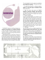
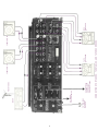
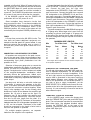
THE MA 6200 INTEGRATED AMPLIFIER
Reading Time: 40 Minutes
Price: $2.00
VARIOUS REGULATORY AGENCIES REQUIRE THAT WE BRING THE FOLLOWING INFORMATION TO YOUR ATTENTION. PLEASE READ IT CAREFULLY.
WARNING: TO PREVENT FIRE OR SHOCK
HAZARD, DO NOT EXPOSE THIS UNIT TO
RAIN OR MOISTURE.
The Mclntosh you have purchased is a Model MA
6200. It has a serial number located on the rear panel
of the chassis. Record that serial number here:
Serial Number
The model, serial number and purchase date are
important to you for any future service. Record the
purchase date here:
Purchase Date
Upon application, Mclntosh Laboratory provides a
Three-Year Service Contract.
Your Mclntosh
authorized Service Agency can expedite repairs
when you provide the Service Contract with the instrument for repair. To assist, record your Service
Contract number here:
Service Contract Number
Your MA 6200 Integrated Amplifier
will give you many years of pleasant and
satisfactory performance. If you
have any questions, please contact:
Contents
CUSTOMER SERVICE
Mclntosh Laboratory Inc.
2 Chambers Street
Binghamton, New York 13903-9990
Phone: 607-723-3512
HOW TO I N S T A L L . . . 2
HOW TO CONNECT... 4
THE FRONT PANEL CONTROLS
AND HOW TO USE T H E M . . . 8
PERFORMANCE LIMITS . . .12
PERFORMANCE CHARTS . . .13,14
TECHNICAL DESCRIPTION .. .15
BLOCK DIAGRAM...17
Take Advantage of 3 years
of Contract Service ...
Fill in the Application NOW.
MclNTOSH THREE YEAR SERVICE CONTRACT
An application for A THREE YEAR SERVICE CONTRACT is included with this manual.
CONTRACT will be cancelled. Damage
by improper use or mishandling is not
covered by the SERVICE CONTRACT.
The terms of the contract are:
4. The SERVICE CONTRACT is issued to
you as the original purchaser. To protect
you from misrepresentation, this contract cannot be transferred to a second
owner.
1. Mclntosh will provide all parts, materials
and labor needed to return the measured
performance of the instrument to the
original performance limits. The SERVICE CONTRACT does not cover any
shipping costs to and from the authorized service agency or the factory.
5. To receive the SERVICE CONTRACT,
your purchase must be made from a
Mclntosh franchised dealer.
2. Any Mclntosh authorized service agency
will repair Mclntosh instruments at normal service rates. To receive service
under the terms of the SERVICE CONTRACT, the SERVICE CONTRACT CERTIFICATE must be presented when the
instrument is taken to the service agency.
6. Your completely filled in application for
SERVICE CONTRACT must be postmarked within 30 days of the date of purchase
of the instrument.
7. To receive the SERVICE CONTRACT, all
information on the application must be
filled in. The SERVICE CONTRACT will
be issued when the completely filled in
application is received by Mclntosh
Laboratory Inc. in Binghamton, New York.
3. Always have service done by a Mclntosh
authorized service agency. If the instrument is modified or damaged as a result
of unauthorized repair, the SERVICE
Copyright 1979 © by Mclntosh Laboratory Inc.
1
The recommended minimum space for installation
is 15 inches (38.1 cm) deep, 17 inches (43.2 cm) wide,
and 6 inches (15.2 cm) high.
To install the instrument in a Mclntosh cabinet,
follow the instructions that are enclosed with the
cabinet. For any other type of installation follow
these instructions:
1. Open the carton and remove the PANLOC
brackets, hardware package, and mounting
template from the carton. Remove the MA 6200 from
its plastic bag and place it upside down on the shipping pallet; unscrew the four plastic feet from the
bottom of the chassis.
2. Mark the cabinet panel.
Place the mounting template in the position on the
cabinet panel where the instrument is to be installed, and tape it in place. The broken lines that represent the outline of the rectangular cutout also represent the outside dimensions of the chassis. Make
sure these lines clear shelves, partitions, or any
equipment. With the template in place, first mark the
six A and B holes and the four small holes that
locate the corners of the cutout. Then, join the four
corner markings with pencil lines, using the edge of
the template as a straightedge.
3. Drill Holes
Use a drill with a 3/16 inch bit held perpendicular to
the panel and drill the six A and B holes. Then, using
a drill bit slightly wider than the tip of your saw
blade, drill one hole at each of two diagonally opposite corners. The holes should barely touch the inside edge of the penciled outline. Before taking the
next step, make sure that the six A and B holes have
been drilled.
4. Saw the Panel Cutout
Saw carefully on the inside of the penciled lines.
First make the two long cuts and then the two short
cuts. After the rectangular opening has been cut out,
use a file to square the corners and smooth any irregularities in the cut edges.
The PANLOC system of installing equipment conveniently and securely is a product of Mclntosh
research. By depressing the two PANLOC buttons
on the front panel, the instrument slide can be locked firmly in place or it can be unlocked so that the
chassis can slide forward, giving you easy access to
the top and rear panels.
The trouble-free life of an electronic instrument is
greatly extended by providing sufficient ventilation
to prevent the buildup of high internal temperatures
that cause deterioration. Allow enough clearance so
that cool air can enter at the bottom of the cabinet
and be vented from the top. With adequate ventilation the instrument can be mounted in any position.
2
5.
Install Mounting Strips
In the hardware package you will find two mounting
strips and two sets of machine screws. For panels
that are less than ½ inch thick, use the ¾ inch
screws; for panels that are more than ½ inch thick,
use the 1¼ inch screws.
Starting at the right-hand side of the panel, insert
a screw of the proper length into the center hole in
the panel, marked B on the template. On the back of
the panel, align a mounting strip with the holes in
the panel and tighten the screw until the screwhead
is pulled into the wood.
Repeat this procedure to attach the mounting
strip to the left side of the panel.
6. Attach PANLOC Brackets
Using two screws of the proper length in the A holes
on each side, attach the PANLOC brackets to the
cabinet panel; the short flange is mounted against
the front (face) of the cabinet panel. The screws
pass through the PANLOC bracket flange, the
cabinet panel, and then through the mounting strips
previously mounted.
7. Install the Instrument
Guide the AC power cord through the panel opening
to the back of the cabinet; then, slide the instrument
into the opening carefully so that the rails on the
bottom of each side of the chassis engage the
tracks on the mounting brackets. Continue to slide
the instrument into the cabinet until it is stopped by
the adjust position latches. Press the latches inward, this permits the instrument to slide into the
cabinet until its front panel is flush with the cabinet
panel. Depress the PANLOC buttons at the lower left
and right corners of the instrument panel to lock the
unit firmly in the cabinet. Depressing the PANLOC
buttons again will unlock the instrument so that it
can slide forward to the adjust position; if you press
inward on the adjust position latches then you can
remove the instrument from the cabinet.
3
How to Connect
Connect a cable from the L TAPE 1 OUTPUT jack
to the left high level input of the tape recorder. Connect a cable from the R TAPE 1 OUTPUT jack to the
right high level input of the tape recorder.
Connect a second recorder in the same manner to
the TAPE 2 OUTPUT jacks.
To Playback/Monitor:
Connect a cable from the left channel output of a
tape recorder to the L TAPE 1 INPUT jack. Connect a
cable from the right channel output of a tape
recorder to the R TAPE 1 INPUT jack.
Connect a second recorder in the same manner to
the TAPE 2 INPUT jacks.
CONNECTING TURNTABLE TO PHONO 1 AND 2
Connect the cable from the "left" channel of the
turntable into the L PHONO 1 INPUT jack. Connect
the "right" channel into the R PHONO 1 INPUT jack.
Connect a second turntable in the same manner
to the PHONO 2 INPUT jacks. Shorting plugs are
shipped in the PHONO 2 INPUT jacks to eliminate
noise if a second turntable is not used. Remove
these shorting plugs when connecting the second
turntable. Keep them for possible future use. DO
NOT plug the shorting plugs into an output jack as
this may prevent operation of the MA 6200.
GROUND CONNECTION
A single ground post is provided. Grounds for turntables, record changers, tape decks, etc. are to be
connected to this post. The left and right program
cables and the ground wire from that source should
be wound or twisted together. To avoid hum make
sure the ground wire does not make any connections to the shields of the left and right program
cables between the program source and the MA
6200.
CONNECTING AC POWER
The MA 6200 AC power cord is to be plugged into
a 120 volt 50/60 Hz wall outlet.
There are two types of AC power outlets on the
back panel of the MA 6200; three black, and two
green.
The green AC power outlets are on at all times.
Plug the AC power cables from the turntable into the
green TURNTABLE power outlets on the rear panel.
CONNECTING A STEREO TUNER AND AUX 1 AND 2
Connect the cable from the "left" channel tuner
output to the L TUNER INPUT jack.
The three black outlets are switched on and off
when the amplifier is turned on or off. These are intended for equalizers and other accessories.
Connect the cable from the "right" channel tuner
output to the R TUNER INPUT jack
The POWER ON pushbutton shares AC power
control, with the AC power switch on a turntable,
through a current detecting switch circuit. On the
rear panel the TURNTABLE AUTO/MANUAL switch
selects the mode of operation.
AUX—Any high level program source such as a
tuner, a TV set or a tape recorder can be connected
to the AUX 1 and 2 INPUT jacks. The connecting procedure is the same as for the tuner input.
When the switch is in the AUTO position and a
turntable plugged into one of the green AC power
outlets, the AC power to the receiver and to the
black AC power outlets can be controlled by the
CONNECTING TAPE RECORDERS
To Record:
4
5
TO 120V 50/60
Hz POWER
SOURCE
TURNTABLE #1
TAPE
RECORDER
1
TURNTABLE #2
CONNECTIONS FOR TUNERS, TURNTABLES, AND TAPE RECORDERS
AC POWER TO
TUNERS, TAPE
RECORDERS,
AND EQUALIZERS.
AC POWER
TO TURNTABLES
TUNER
FM ANTENNA
TAPE
RECORDER
2
Connect the leads from the left main loudspeaker
to the SPEAKER 1 Left and Common push connectors. Connect the lead from the right main
loudspeaker to the SPEAKER 1 Right and Common
push connectors. Connect the leads from a second
left loudspeaker to the SPEAKER 2 Left and Common push connectors. Connect the lead from a second right loudspeaker to the SPEAKER 2 Right and
Common push connectors. Connect the leads from
a third left loudspeaker to the SPEAKER 3 Left and
Common push connectors. Connect the lead from a
third right loudspeaker to the SPEAKER 3 Right and
Common push connectors.
turntable on/off switch. When AC power to the turntable is turned on, automatically the instrument and
the SWITCHED black AC power outlets are turned
on. The system will remain on until the turntable is
turned off. The POWER ON pushbutton controls the
AC power for any source other than the turntable.
In the MANUAL position only the POWER ON
pushbutton will turn AC power on or off.
Some turntables have electronic circuits that
draw current all the time. To use these turntables the
AUTO/MANUAL switch must be in the MANUAL
position. With the AUTO/MANUAL switch in the
MANUAL position, AC power to the system will be
controlled by the front panel POWER pushbutton only.
The push connector on the MA 6200 will accept up
to 16 gauge wire. When larger wire is used it will be
necessary to splice a short length of 16 gauge wire
to the ends of the heavier wire to make connections.
A similar arrangement may be required to connect at
the speakers.
FUSES
A 5-amp fuse protects the MA 6200 circuits. The
fuse does not protect additional equipment connected to the rear panel AC power outlets. A one
amp fuse protects the turntable auto on circuit. If
this fuse fails, power to the green outlets will be interrupted.
Wire
Gauge
22
20
18
16
14
12
10
CONNECTING LOUDSPEAKERS FOR STEREO
All speakers are connected to the push connectors on the rear panel. When stereo speakers have
been connected to the proper push connectors, the
corresponding front panel pushbuttons turn the
speakers on or off.
MAXIMUM WIRE LENGTHS
For 8 Ohm Load
For 4 Ohm Load
Feet
Meters
Feet
Meters
6
10
15
25
40
60
100
1.8
3.1
4.6
7.6
12.2
18.3
30.5
12
20
30
50
80
120
200
3.7
6.1
9.1
15.2
24.4
36.6
66.0
Wire lengths above represent the wire resistance equal to 5%
of the speaker impedance.
Selection of the proper gauge wire to connect the
loudspeakers preserves the quality of sound reproduction for which the loudspeakers have been designed. If undersize wire is used, resistance is added
to the amplifier/loudspeaker combination which
adversely affects the performance. Added resistance causes reduction of damping characteristics,
modification of frequency response and reduction in
power output.
CONNECTING ONE LOUDSPEAKER FOR MONO
The left and right outputs of the MAC 6200 must connect to separate loudspeakers. Do not parallel the
output connections for a single loudspeaker. If the
left and right outputs are connected together excessive heat is generated in the power amplifiers
which causes damage even though the MODE
SELECTOR pushbutton is in the MONO position. If
you wish to drive a single loudspeaker, put the
MODE SELECTOR in MONO and connect the loudspeaker to the left or the right speaker push connectors only. It is not necessary to connect a load to the
other channel output.
Use lamp cord, bell wire, or wire with similar type
of insulation to connect the speakers to the amplifier. In all cases, the leads to and from the speaker
should be twin conductor or twisted together. When
using 8 ohm speakers and for the normally short
distances of under 30 feet between the amplifier and
speaker, No. 18 wire or larger can be used. For
distances over 30 feet between the amplifier and
speaker use larger diameter wire. Select the correct
size wire for the wire length from the chart. It is
recommended that the DC resistance of the speaker
leads be less than 5% of the speaker impedance. Up
to 10% can be tolerated. Resistance of the leads
should be computed for the length of wire both to
and from the speaker or speakers.
For multiple speaker operation, run separate
leads from the amplifier to the speakers.
CONNECTING A MclNTOSH EQUALIZER
On the JUMPER panel, remove the jumpers between the PREAMP OUT jacks and power AMP INput
jacks. The environmental equalizer is connected between these jacks. Use standard shielded cables.
Connect the PREAMP OUT to the input of the
equalizer. Connect the output of the equalizer to the
power AMP INput jack.
6
7
LEFT
SPEAKER SYSTEM #1
RIGHT
RIGHT
LEFT
SPEAKER SYSTEM #3
RIGHT
CONNECTIONS FOR ENVIRONMENTAL EQUALIZER AND LOUDSPEAKERS
LEFT
SPEAKER SYSTEM #2
CUSTOM
ENVIRONMENTAL
EQUALIZER
The Front Panel Controls and
How to use Them
INPUT SELECTOR
response has been shaped according to the RIAA
standard to compensate for the characteristics of a
magnetic phono cartridge.
PHONO 2: Same as PHONO 1 but for a second
phono system.
The INPUT SELECTOR Is a five position switch
that connects the chosen input program to the proper circuits in the MA 6200.
AUX 1: Connects to the high level input, any output from a high level program source requiring flat
amplification. Such a source could be a television
set, playback from another tape recorder, an additional tuner, etc.
MODE SELECTOR
The MODE SELECTOR facilitates the accurate adjustment of a stereo system for some differences
caused by room acoustics, loudspeaker placement
and the other components used in the system.
The MODE SELECTOR switch connects the program to the loudspeaker in seven ways:
L to L and R: Connects the left program to both
loudspeakers.
R to L and R: Connects the right program to both
loudspeakers.
AUX 2: Same as AUX 1 but for a second high level
program source.
TUNER: Connects the output from any AM, FM or
MPX FM tuner to the high level input stage. In the
TUNER position the MA 6200 has flat amplification.
PHONO 1: Connects the output of any magnetic
phono cartridge to the low level input stage. The
8
Frequency response is flat and there is no
loudness compensation when the knob is turned fully counter-clockwise to the "flat" position.
STEREO REV: Connects the left program to the
right loudspeaker and the right program to the left
loudspeaker.
STEREO: Connects the left program to the left
loudspeaker and the right program to the right
loudspeaker.
EQUALIZER FREQUENCY CONTROLS
Each of five EQUALIZER FREQUENCY controls
modifies upward or downward the tone balance of a
band of frequencies centered on the frequency
marked above the control. The flat position of the
control has a detent for easy reference. Each control
provides 12 dB boost or cut at the specified center
frequency.
MONO (L + R): Adds the left and right programs
together and connects to both loudspeakers.
L + R to L: Connects the left plus right program to
the left loudspeaker only.
L + R to R: Connects the left plus right program to
the right loudspeaker only.
VOLUME CONTROL
The VOLUME control
is a precision step control manufactured for
Mclntosh Laboratory. It
has 32 steps with a 70
dB range, plus volume
off. Left and right channel tracking are within
1 dB. This extreme accuracy is obtained through
special electronically controlled resistance element
trimming.
Use the EQUALIZER FREQUENCY controls to
modify the sound and tone balance of program
material. Here are some suggestions from which to
start:
Problem
Equalizer Correction
Bass too weak
Raise 30 and/or 150
Male vocalist needs reinforcing
Raise 150
Female vocalist reinforcing
Raise 500
Hum on program
Reduce 30
Violins, trumpets dull
Raise 1500
Drum "brushes" not audible
Raise 10 K
BALANCE and
LOUDness CONTROLS
The BALANCE and
LOUDness controls are
concentric. The BALANCE control [large
outer knob] adjusts for
equal volume of either
the left or right channels. The volume of the channels can be varied
relative to each other.
HEADPHONE JACKS
The front panel HEADPHONE jacks have been
designed to feed low impedance dynamic headphones. Electrostatic headphones generally require
higher power than dynamic headphones. They must
be connected to the speaker push connectors on the
rear panel.
Plug headphones into either front panel HEADPHONE jack. Adjust the front panel VOLUME control
for comfortable headphone listening.
Signal to the headphone jacks is not affected by
the SPEAKER switches.
l e f t . . . turning the control to the left accents the left
channel by reducing the right channel output.
right . . . turning the control to the right accents the
right channel by reducing the left channel output.
The LOUDness control [small center knob] increases both bass and treble frequencies of both
channels as it is turned clockwise. Adjustment of
the LOUDness control allows life-like frequency
balance when playing music softly. Its frequency
response contour is accurately modeled after the
family of "Equal Loudness" curves identified by
Fletcher and Munson.
TAPE PUSHBUTTONS
IMPORTANT: When the MA 6200 is operated with
either MONITOR pushbutton at the in position, the
program heard will be that from the tape recorders
only. Signal from any other source will not be heard
from the loudspeakers. To hear any other source,
make sure the MONITOR pushbuttons are OUT.
The MONITOR switches are mechanically interlocked to prevent simultaneous monitoring from
two tape recorders. If one button is at the in position, it must be pushed again to release it to the out
position before the other button can be pushed.
The loudness circuitry is completely independent
of the volume control. Therefore, any desired
amount of compensation can be introduced
regardless of volume control position.
9
The MA 6200 is designed so it may be used with
two tape recorders. The four left pushbuttons control the signal output of these recorders. They permit
recordings to be monitored as they are being recorded, or copying of tapes from one recorder to another
while listening to a separate program or the playback of either recorder.
MONITOR TAPE 1 pushbutton out: The program
source as selected by the INPUT SELECTOR is fed
to the power amplifiers and heard through the
loudspeakers; pushbutton in: Signal from a tape
recorder plugged into INPUTS TAPE 1 is fed to the
power amplifiers and heard through the loudspeakers.
MONITOR TAPE 2 Pushbutton: Functions similarly to monitor Tape 1. It also controls the program
from a tape recorder plugged into the front panel
TAPE jacks. When a tape recorder is plugged into
the front jacks the tape input circuit is transferred
from the rear TAPE 2 IN jack to the front jack. The
tape recorder plugged into the TAPE 2 IN jack on the
rear panel is automatically disconnected.
nected. A metal shielded 1/4 inch stereo phone plug
is used for best shielding. Connections follow the industry standards and are tip: left signal, ring: right
signal, and sleeve: common ground.
SPEAKERS 1, 2 and 3 PUSHBUTTONS
When each of these pushbuttons is pushed in, a
pair of loudspeakers is connected to the power
amplifier outputs. Speaker 1, 2 and 3 may be
selected one at a time, any combination or all at
once.
POWER ON PUSHBUTTON
The POWER ON pushbutton shares AC power
control, through a current detecting switch circuit,
with the AC power switch on a turntable. On the rear
panel the TURNTABLE AUTO/MANUAL switch
selects the mode of operation.
When the switch is in the AUTO position and a
turntable is plugged into one of the green AC power
outlets the AC power to the MA 6200 and to the black
AC power outlets can be controlled by the turntable
on/off switch. When AC power to the turntable is
turned on, automatically the MA 6200 and the SWITCHED black AC power outlets are turned on. The
system will remain on until the turntable is turned
off. The POWER ON pushbutton switch parallels the
automatic turntable power control feature. The
POWER ON pushbutton is used to turn on and off
power when the turntable is not used. The POWER
ON pushbutton must be out or off for the turntable
to control the AC power.
In the MANUAL position only the POWER ON
pushbutton will turn the MA 6200 and black outlet
AC power on and off.
TAPE COPY T1 T2 pushbutton in: connects the
output from tape recorder 1 to the input of tape
recorder 2 without affecting the program being
heard from the speakers. In this position a copy of
the program on tape recorder 1 can be made on tape
recorder 2. To monitor the original use MONITOR
TAPE 1 pushbutton and to monitor the copy use
MONITOR TAPE 2 pushbutton.
TAPE COPY T2 T1 pushbutton in: connects the
output from tape recorder 2 to the input of tape
recorder 1 without affecting the program being
heard from the speakers. In this position a copy of
the program on recorder 2 can be made on recorder
1. To monitor the original use MONITOR TAPE 2
pushbutton and to monitor the copy use MONITOR
TAPE 1 pushbutton.
POWER GUARD INDICATOR LAMPS
POWER GUARD assures that the power amplifier
section of the MA 6200 can not be over driven, thus
amplifier output clipping is eliminated. Clipping is
caused when the amplifier is asked to produce more
power output than it can deliver with low distortion.
Amplifiers are capable of delivering large quantities
TAPE RECORDER FRONT PANEL CONNECTION
Input and output facilities are available at the
TAPE IN-OUT jacks on the front panel. These front
panel jacks make connections without having to get
at the rear panel. When using the front panel jacks,
the rear TAPE 2 IN jack is automatically discon10
of power when they
are driven to clipping
and can have more
than 40% harmonic
distortion. The extra
energy content of the
clipped signal will
damage most speakers. A Mclntosh advancement helps to
protect your speaker
from this kind of damage. The MA 6200 has a built in
"waveform comparator" that compares the wave
shape of the input signal with the output signal. If
the non-linearity between the two signals exceeds
0.5% the POWER GUARD circuit operates. Operation is indicated when the red limit indicators turn
on. As long as the amplifier operates without
overload the normal indicator illuminates.
PUSHBUTTON INDICATOR LAMPS
These are eight red indicator lamps above the
pushbutton switches. They indicate the function
selected by the corresponding pushbutton. These indicators are also connected to an internal thermal
overload protector circuit. In the event of high internal temperatures these indicators will extinguish
and output power will be disconnected from the
loudspeaker. When the unit cools normal operation
will be restored.
11
Performance Limits
Tape & Aux Input: 100 dBA, 95 dB unweighted,
below rated output
Phono Input:
85 dBA, 80 dB unweighted,
below 10 mV input
We promise you that the MA 6200 you buy must be
capable of performance at or exceeding these limits
at the time of purchase or you get your money back.
Mclntosh PERFORMANCE LIMITS are the maximum
departure from perfection permitted for a Mclntosh
instrument.
DAMPING FACTOR
Greater than 30
PERFORMANCE
Mclntosh audio power ratings are in accordance
with the Federal Trade Commission Regulation of
November 4, 1974 concerning power output claims
for amplifiers used in home entertainment products.
INPUT SENSITIVITY AND IMPEDANCE
Power Amp: 2.5 Volts
22,000 ohms
Tape & Aux: 250 mV
100,000 ohms
Phono:
2 mV
47,000 ohms, 100pf
POWER OUTPUT
100 Watts minimum sine wave continuous
average power output per channel, both channels
operating into 4 ohms, 20 Hz to 20 kHz, with no more
than .05% total Harmonic Distortion.
75 Watts minimum sine wave continuous average
power output per channel, both channels operating
into 8 ohms, 20 Hz to 20 kHz, with no more than .05%
total Harmonic Distortion.
TAPE OUTPUT
Aux, Tape: 250 mV with rated input
Phono:
250 mV with rated input
PROGRAM EQUALIZER
± 12 dB at 30, 150, 500, 1,500, and 10,000 Hz
POWER REQUIREMENT
120 Volts, 50/60 Hz, 0.5 to 4 amps (50 to 400 watts).
OUTPUT LOAD IMPEDANCE
4 ohms, 8 ohms.
SEMICONDUCTOR COMPLEMENT
42 Transistors
13 Integrated Circuits
25 Diodes
1 Silicon Controlled Rectifier
RATED POWER BAND
20 Hz to 20 kHz
TOTAL HARMONIC DISTORTION
.05% maximum at any power level from 250
milliwatts to rated power per channel, 20Hz to
20kHz, both channels operating.
MECHANICAL INFORMATION
SIZE: Front Panel measures 16 inches wide (40.6
cm) by 5 7/16 inches high (13.8 cm). Chassis
measures 14 3/4 inches wide (37.5 cm) by 4 13/16 inches high (12.2 cm) by 13 inches deep (33.0 cm), including PANLOC shelf and back panel connectors.
Knob clearance required is 1 1/4 inches (3.2 cm) in
front of the mounting panel.
FINISH: Front panel is anodized gold and black
with special gold/teal nomenclature illumination.
Chassis is black.
MOUNTING: Exclusive Mclntosh developed professional PANLOC
WEIGHT: 30 pounds (13.6 kg) net. 42 pounds (19.1
kg) in shipping carton
INTERMODULATION DISTORTION
.05% maximum at any power level from 250
milliwatts to rated power per channel with both
channels operating for any combination of frequencies 20 Hz to 20 kHz.
FREQUENCY RESPONSE
20 Hz to 20 kHz +0, -0.5 dB at rated power
HUM AND NOISE
Power Amp:
105 dBA, 100 dB unweighted,
below rated output
12
Performance Charts
HARMONIC DISTORTION IN PERCENT
POWER OUTPUT SECTION
HARMONIC DISTORTION VS POWER
RL = 8 OHMS, BOTH CHANNELS OPERATING
0.1
.08
.06
.04
-02
0
1
0.1
10
POWER OUTPUT IN WATTS
100
1k
10k
100k
POWER OUTPUT SECTION
BOTH CHANNELS OPERATING
.05% THD POWER BANDWIDTH
POWER OUTPUT IN WATTS RMS
120
100
80
60
40
20
0
100
1k
FREQUENCY Hz
OUTPUT SIGNAL WAVEFORM SHOWING ACTION
OF POWER GUARD TO ELIMINATE OUTPUT SIGNAL
CLIPPING. AMPLIFIER INPUT IS OVERDRIVEN BY
20 dB FOR BOTH OSCILLOGRAM TRACES.
INTERMODULATION DISTORTION
vs.
POWER OUTPUT
8 OHM OUTPUT
INPUT FREQUENCIES 60 Hz AND 7 kHz
INPUT RATIO: 4.1
OUTPUT SIGNAL AMPLITUDE
INTERMODULATION DISTORTION IN PERCENT
10
.3
.2
.1
0
.1
1
10
100
POWER OUTPUT IN EQUIVALENT AVERAGE WATTS
TIME
13
LOUDNESS RESPONSE
RESPONSE IN dB
20
15
10
5
0
20
100
1k
FREQUENCY IN HERTZ
10k
20k
10k
20k
FREQUENCY RESPONSE OF
EQUALIZER FREQUENCY CONTROLS
SET AT MAXIMUM AND MINIMUM
RESPONSE IN dB
20
10
0
-10
-20
20
100
1k
FREQUENCY IN HERTZ
PHONO EQUALIZATION (RIAA) RESPONSE
20
RESPONSE IN dB
15
10
5
0
-5
-10
-15
-20
100
1k
FREQUENCY IN HERTZ
14
10k
20k
Technical Description
Munson equal loudness compensation. A potentiometer is placed between these two feedback
loops making it possible to select any combination
of the two from a flat response to full loudness compensation. The overall gain of the stage is 20 dB and
is not affected by the position of the loudness control at mid frequencies.
AUDIO SECTION
Each channel of the MA 6200 has four basic sections. They are: phono preamplifier, high level and
loudness amplifier, equalizer amplifier, and power
amplifier.
PHONO PREAMPLIFIER
The phono preamplifier uses a high technology integrated circuit operational amplifier. Its differential
input stage has been optimized for low noise and
low distortion performance. Open loop gain of this
integrated circuit is 100,000. With high open loop
gain a large amount of negative feedback can be used around the phono preamplifier to further reduce
noise and distortion. The feedback network also provides precision RIAA frequency compensation. The
network uses 1% metal film resistors and 5% poly
film capacitors. To achieve low noise performance it
is essential that the feedback network be very low
impedance. As a consequence, the preamplifier
must be capable of operating as a power amplifier to
drive this impedance. The actual power output
capability of this preamplifier stage is more than 100
milliwatts, a great margin beyond that which is required.
Input sensitivity of the phono preamplifier is 2
millivolts. The gain of the amplifier is 42 dB at 1000
Hz. The phono preamplifier has a very wide dynamic
range. At 1000 Hz the phono input circuit will accept
100 millivolts without overload, a voltage far greater
than the output of any current magnetic phono cartridge. Phono input overload therefore is virtually impossible. A signal level of 10 millivolts at the phono
input at 1000 Hz will produce 1.2 volts at the tape
output. The tape output has a source impedance of
200 ohms. For most efficient signal transfer the tape
output should operate into a load impedance of
5,000 ohms or greater.
EQUALIZER AMPLIFIER
The equalizer amplifier is constructed with the
same operational amplifiers as used in previous
amplifiers. Five other operational amplifiers are
each arranged in an active circuit configuration that
is the equivalent of a series tuned circuit, one at
each of the five center frequencies. Each series tuned circuit is inserted, via the equalizer control potentiometer, in either the input circuit or feedback circuit of the equalizer amplifier thereby providing a
boost and cut capability of 12 dB for each band of
frequencies.
POWER AMPLIFIER
The input impedance of the power amplifier is
22,000 ohms and requires 2.5 volts rms to drive the
amplifier to rated output. The short jumpers on the
rear panel of the MA 6200 connect the equalizer
amplifier output [PREAMP OUT] and power amplifier
input [AMP IN]. At the input of the power amplifier
two transistors are connected as a differential
amplifier. The two input signals to the differential
amplifier are the input signal and the negative feedback signal from the power amplifier. The differentia! amplifier permits the best use of negative feedback to maintain low noise and low distortion performance. The outputs of the differential amplifier are
combined in a current mirror to a single output. The
current mirror feeds a linear voltage amplifier which
in turn drives two medium power driver transistors.
The drive transistors feed the output stages. The
output section is arranged as a fully complementary
direct coupled series push/pull amplifier. The power
transistors used in the output circuit are selected for
their high power dissipation capability, wide frequency response, and large safe operating area. The
power transistors are mounted on large black
anodized heat sinks to assure that under normal
operating conditions the transistors will operate at a
low temperature. If operating temperatures should
increase due to a shorted speaker or restricted ventilation, an automatic sensing device turns the
speaker circuit off. The speaker circuit will turn on
again when the temperature has returned to its normal limits. This additional protection assures you of
reliability even under the most extreme operating
HIGH LEVEL AMPLIFIER
At the input to the high level or loudness amplifier
the signal passes through the mode switch, then
through the volume control, and into the amplifier. In
the past loudness controls have typically used simple passive circuits connected to a tap on the
volume control. As a consequence, compensation
accuracy was dependent on many variables such as
volume control position and differences in input
level. The MA 6200 uses active circuitry. The same
type of integrated circuit operational amplifier that
is used in the phono amplifier is used here. It has
two feedback loops. One feedback loop is flat. The
other feedback loop conforms to the Fletcher15
conditions. To further insure reliability a special
power output SENTRY MONITORING CIRCUIT
prevents failure of the power amplifier transistors
due to excessive mismatch or shorting of the output.
When the MA 6200 operates normally the SENTRY
MONITORING CIRCUIT has no e f f e c t on signals
passing through the power amplifier. If the power
dissipation in the output transistors should rise
above normal design limits the SENTRY MONITORING CIRCUIT restricts the drive to the output stage
which reduces the dissipation in the output transistors. The SENTRY MONITORING CIRCUIT acts instantaneously for any input signal or load combination. This arrangement assures circuit reliability. Only Mclntosh gives you this degree of protection.
occurs when an amplifier is asked to exceed its
design limits and the capacity of the power supply.
Since POWER GUARD does not begin to work until
this point is reached, the power capability of the
amplifier is never affected.
TURN ON DELAY
The MA 6200 has transient-free turn on and turn
off characteristics. A heavy duty relay, timecontrolled by a transistor switch, connects the output to the speakers. The control to the transistor
switch is derived from a long time constant
capacitor charging network that turns the relay on
approximately two seconds after the power switch
is turned on. The same circuit has a short turnoff
time constant and the relay drops out before the
amplifier's main power supply has a chance to
discharge.
The direct coupled complementary amplifier circuit holds the output at DC ground potential when
there is no signal input which eliminates the need
for a coupling capacitor in the output. The MA 6200
power amplifier is all direct coupled to insure maximum low frequency performance. In most direct
coupled circuits, failure of any transistor in the
power amplifier will cause a DC potential to appear
in the output. To assure that no damaging or interfering DC appears across the output terminals, a
special, very fast acting protector circuit constantly
monitors the output circuit for DC. If, at any time, a
constant DC level appears, the speakers are disconnected. The protective circuit reacts in milliseconds.
Speakers remain disconnected until the cause has
been fixed. Under normal operating conditions the
protective circuit has no a f f e c t on the operation of
the output circuit. This is another example of Mclntosh continuous protection.
POWER SUPPLY
Two high current power supplies - a positive 48
volt and a negative 48 volt DC - are used to drive the
output power amplifier. Very large filter capacitors,
12,000 microfarads each, are used to store a large
amount of energy to provide good filtering and excellent voltage regulation. Good low frequency
response and negligible low frequency distortion in
the power amplifier stages depends on the regulation of the power supply. Two additional electronically regulated power supplies are used in the
MA 6200. A + 18 volt and a - 18 volt line supply all
operational amplifiers.
POWER GUARD
Amplifiers are capable of delivering large quantities of power when they are driven to clipping. Clipping is caused when the amplifier is asked to produce more power output than it can deliver with low
distortion. A clipped amplifier can have more than
40% harmonic distortion. The extra energy content
of the clipped signal will damage most loudspeakers, particularly delicate high frequency
tweeters. A new Mclntosh advancement helps protect your speakers from this kind of damage. The MA
6200 has a built-in waveform comparator which compares the wave shape of the input signal with the
output signal. If the disparity between the two
signals exceeds 0.5% [equivalent to 0.5% total harmonic distortion] a red limit indicator illuminates.
With any further increase in distortion the POWER
GUARD circuit will operate. This circuit limits the input dynamically so that the amplifier can not be overdriven. POWER GUARD eliminates amplifier output
clipping.
POWER GUARD does not limit the dynamic range
or the power output of the power amplifier. Clipping
16
17
MclNTOSH MA 6200 INTEGRATED AMPLIFIER
Block Diagram
MclNTOSH LABORATORY INC.
2 CHAMBERS ST., BINGHAMTON, N.Y. 13903-2699
607-723-3512
The continuous improvement of its products is the policy of
Mclntosh Laboratory Incorporated who reserve the right to
improve design without notice.
Printed in U.S.A.
039179
BE032003