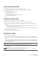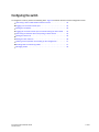
1
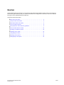
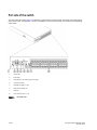
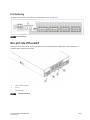
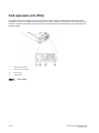
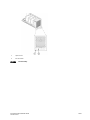
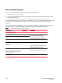
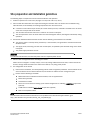
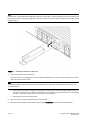
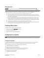
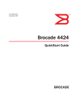
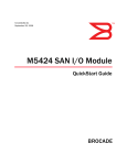
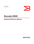
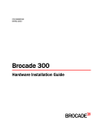
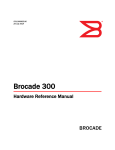
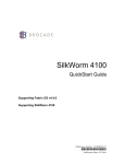
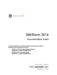
53-1001118-01
18 August 2008
Brocade Encryption Switch
QuickStart Guide
Supporting Fabric OS v6.1.1_enc
53-1001118-01
*53-1001118-01*
18 August 2008
Copyright © 2008 Brocade Communications Systems, Inc. All Rights Reserved.
Brocade, the Brocade B weave logo, Secure Fabric OS, and SilkWorm are registered trademarks of Brocade Communications Systems, Inc., in the
United States and/or in other countries. FICON, IBM
BladeCenter are registered trademarks of IBM Corporation in the U.S. and other
countries. All other brands, products, or service names are or may be trademarks or service marks of, and are used to identify, products or
services of their respective owners.
Notice: The information in this document is provided “AS IS,” without warranty of any kind, including, without limitation, any implied warranty of
merchantability, noninfringement or fitness for a particular purpose. Disclosure of information in this material in no way grants a recipient any
rights under Brocade's patents, copyrights, trade secrets or other intellectual property rights. Brocade reserves the right to make changes to this
document at any time, without notice, and assumes no responsibility for its use.
The authors and Brocade Communications Systems, Inc. shall have no liability or responsibility to any person or entity with respect to any loss,
cost, liability, or damages arising from the information contained in this book or the computer programs that accompany it.
Notice: The product described by this document may contain “open source” software covered by the GNU General Public License or other open
source license agreements. To find out which open source software is included in Brocade products, view the licensing terms applicable to the
open source software, and obtain a copy of the programming source code, please visit http://www.brocade.com/support/oscd.
Export of technical data contained in this document may require an export license from the United States Government.
Brocade Communications Systems, Incorporated
Corporate Headquarters
Brocade Communications Systems, Inc.
1745 Technology Drive
San Jose, CA 95110
Tel: 1-408-333-8000
Fax: 1-408-333-8101
Email: [email protected]
Asia-Pacific Headquarters
Brocade Communications Singapore Pte. Ltd.
9 Raffles Place
#59-02 Republic Plaza 1
Singapore 048619
Tel: +65-6538-4700
Fax: +65-6538-0302
Email: [email protected]
European and Latin American Headquarters
Brocade Communications Switzerland Sàrl
Centre Swissair
Tour A - 2ème étage
29, Route de l'Aéroport
Case Postale 105
CH-1215 Genève 15
Switzerland
Tel: +41 22 799 56 40
Fax: +41 22 799 56 41
Email: [email protected]
Document History
Document Title
Publication Number
Summary of Changes
Publication Date
Brocade Encryption Switch QuickStart
Guide
53-1001118-01
New document.
August 2008
2 of 20
Encryption Switch QuickStart Guide
53-1001118-01
Overview
This QuickStart guide is intended as an overview to help experienced installers unpack, install, and configure a
Brocade Encryption Switch quickly. For detailed installation and configuration instructions, refer to the Brocade
Encryption Switch Hardware Reference Manual.
This guide include these topics.
• Port side of the switch . . . . . . . . . . . . . . . . . . . . . . . . . . . . . . . . . . . . . . . . . . .
• Non-port side of the switch . . . . . . . . . . . . . . . . . . . . . . . . . . . . . . . . . . . . . . .
• Field-replaceable units (FRUs). . . . . . . . . . . . . . . . . . . . . . . . . . . . . . . . . . . . .
• Time and items required . . . . . . . . . . . . . . . . . . . . . . . . . . . . . . . . . . . . . . . . .
• Site preparation and installation guidelines. . . . . . . . . . . . . . . . . . . . . . . . . .
• Items included with the switch . . . . . . . . . . . . . . . . . . . . . . . . . . . . . . . . . . .
• Installing a standalone switch . . . . . . . . . . . . . . . . . . . . . . . . . . . . . . . . . . . .
• Powering on the switch . . . . . . . . . . . . . . . . . . . . . . . . . . . . . . . . . . . . . . . . .
• Configuring the switch . . . . . . . . . . . . . . . . . . . . . . . . . . . . . . . . . . . . . . . . . .
• Powering off the switch . . . . . . . . . . . . . . . . . . . . . . . . . . . . . . . . . . . . . . . . .
• Configuring for encryption . . . . . . . . . . . . . . . . . . . . . . . . . . . . . . . . . . . . . . .
Encryption Switch QuickStart Guide
53-1001118-01
4
5
6
8
9
10
10
10
11
19
19
3 of 20
Port side of the switch
The port side of the switch (Figure 1) includes the switch power and status LEDs, clustering and re-keying ports,
Smart Card reader, management, console, and USB port, and the Fibre Channel ports and their corresponding
status LEDs.
1
Status LED
2
Power LED
3
RJ45 GE ports (for clustering and re-keying)
4
Smart Card reader
5
RJ45 GE management port
6
RJ45 Serial console port
7
USB port
8
Fibre Channel ports (0 - 31)
FIGURE 1
4 of 20
Port-side view
Encryption Switch QuickStart Guide
53-1001118-01
Port Numbering
The Fibre Channel ports on the switch are numbered from 0 to 31 (Figure 2).
FIGURE 2Port numbering
Non-port side of the switch
The non-port side of the switch (Figure 3) includes the two redundant power supply FRUs, three redundant fan
assembly FRUs, and their status LEDs.
1
Power supply (2)
2
Power supply status LED
3
Fan (3)
4
Fan status LED
FIGURE 3
Non-port side view
Encryption Switch QuickStart Guide
53-1001118-01
5 of 20
Field-replaceable units (FRUs)
The switch has two power supply (Figure 4) and three fan assembly (Figure 5) FRUs that are redundant and hot
swappable. The FRUs are capable of functioning universally (100 - 240 VAC input range) without voltage jumpers or
switches. The power supply FRUs are identical and interchangeable; the fan assembly FRUs are also identical and
interchangeable.
1
Power-cord connection
2
Power supply status LED
3
Power switch
4
Captive screw
FIGURE 4
6 of 20
Power supply
Encryption Switch QuickStart Guide
53-1001118-01
1
Captive screw
2
Fan status LED
FIGURE 5
Fan assembly
Encryption Switch QuickStart Guide
53-1001118-01
7 of 20
Time and items required
You can set up and install the Brocade Encryption Switch in the following ways:
• As a standalone unit on a flat surface.
• In a 19-in. Electronic Industries Association (EIA) cabinet, using the Fixed Rack Mount Kit (optional) or Slide
Rack Mount Kit (optional).
• In a mid-mount telecommunications (Telco) rack, using the Mid-Mount (Switch) Rack Kit (optional).
This chapter describes how to set up the switch as a standalone unit. For rack-mount installation instructions, refer
to the Fixed Rack Mount Rack Kit, the Slide Rack Mount Kit, or the Mid-Mount (Switch) Rack Kit Installation
Procedure.
Table 1 describes the main installation and setup tasks and the estimated time required for each, based. These
time estimates assume a prepared installation site and appropriate power and network connectivity.
TABLE 1
Installation tasks, time, and items required
Installation task
Time estimate
Items required
Site preparation and unpacking the
Brocade Encryption Switch
30 minutes
None
Installing the rack mount kit
30 minutes
Mounting and securing the switch in the
rack
15 minutes
Refer to the Fixed Rack Mount Kit Installation
Procedure, the Slide Rack Mount Kit
Installation Procedure, or the Mid-Mount
(Switch) Rack Kit Installation Procedure.
Installing power cables and powering on
the switch,
10 minutes
Power cables (provided in the accessory kit).
Establishing serial connection, logging on
to the switch, and configuring the IP
addresses.
20 minutes
Serial cable (provided in the accessory kit).
Workstation computer with a serial port or
terminal server port and a terminal emulator
application (such as HyperTerminal).
Ethernet IP addresses for the switch.
Installing Ethernet cable and configuring
the switch domain ID, date and time, and
additional system parameters. Verify and
backup configuration.
20 minutes
Ethernet cable for Telnet access.
Refer to the Fabric OS Administrator’s Guide.
Installing SFPs. Attaching and managing
fiber optic cables.
15 minutes
SFP optical transceivers. Fiber optic cables
and cable ties.
8 of 20
Encryption Switch QuickStart Guide
53-1001118-01
Site preparation and installation guidelines
The following steps are required to ensure correct installation and operation.
1. Provide a space that is 2 rack units (2U) high. 1U is equal to 4.45 cm (1.75 in.).
2. Plan to install the switch with the nonport side facing the air-intake aisle. The switch can be installed facing
either direction, if serviceability and cooling requirements are met. Ensure that:
• A minimum of 53 cubic feet per minute (90.1 cubic meters per hour) of airflow is available to the air intake
vents on the nonport side of the switch.
• The air intake and exhaust vents have a minimum of 2 inches of airspace.
• The air temperature on the air intake side is less than 40 degrees Celsius (104 degrees Fahrenheit) during
operation.
3. Ensure that dedicated electrical branch circuits with the following characteristics are available:
• The primary outlet is correctly wired, protected by a circuit breaker, and grounded in accordance with local
electrical codes.
• The supply circuit, line fusing, and wire size are adequate, as specified by the electrical rating on the switch
nameplate.
• The power supply standards are met.
ATTENTION
To maximize fault tolerance, connect each power cord to a separate power source.
4. Plan for cable management before installing the chassis.
Cables can be managed in a variety of ways, such as by routing cables below the chassis, to either side of the
chassis, through cable channels on the sides of the cabinet, or by using patch panels.
5. For configuration of the switch:
• Plan for two IP addresses, and corresponding subnet masks and gateway addresses. One IP address for the
virtual IP address on the cluster interconnect; and another IP address for the management port.
• Ensure that the following is available:
• Workstation with an installed terminal emulator, such as HyperTerminal
• Serial cable (provided)
• Three Ethernet cables
• Access to an FTP server for backing up the switch configuration or collecting supportsave output data
(optional)
• A USB stick for collecting supportsave output data (optional)
• SFPs and compatible cables
NOTE
For information about the SFP transceivers that are qualified for the Brocade Encryption Switch, go to
http://www.brocade.com/products/interop_and_compatibility.jsp.
Encryption Switch QuickStart Guide
53-1001118-01
9 of 20
Items included with the switch
The following items are included with the standard shipment of the switch.
• The Brocade Encryption Switch, containing two power supplies and three fan assemblies
• One accessory kit containing:
• Serial cable with an RJ-45 connector.
• Two 6 ft. power cords
• Rubber feet for setting up the switch as a standalone unit
• Brocade family documentation CD
Installing a standalone switch
To install the switch as a standalone unit, complete the following steps.
1. Unpack the switch and verify the items listed in “Items included with the switch” are present.
2. Apply the adhesive rubber feet. The rubber feet help to prevent the switch from sliding off the supporting
surface.
a.
Clean the indentations at each corner of the bottom of the switch to ensure that they are free of dust or
other debris that might lessen the adhesion of the feet.
b.
With the adhesive side against the chassis, place one rubber foot in each indentation and press into place.
3. Place the switch on a flat, sturdy surface.
4. Provide power to the switch (“Powering on the switch”).
Powering on the switch
Follow these steps to power on the switch.
1. Connect the power cords to both power supplies and then to power sources on separate circuits to protect
against AC failure. Ensure that the cords have a minimum service loop of 6 in. available and are routed to avoid
stress.
2. Power on the power supplies by flipping both AC switches to the “1” symbol. The power supply LEDs display
amber until POST is complete, and then change to green. The switch usually requires approximately 3 minutes
to boot and complete POST.
NOTE
Power is supplied to the switch as soon as the first power supply is connected and turned on.
3. After POST is complete, verify that the switch power LED on the port side is green and the switch status LED on
the port side is off.
ATTENTION
Do not connect the switch to the network until the IP address is set.
10 of 20
Encryption Switch QuickStart Guide
53-1001118-01
Configuring the switch
To configure the switch, perform the following tasks. Figure 6 illustrates the flow of these configuration tasks.
• Connecting a serial cable between switch and host . . . . . . . . . . . . . . . . . .
• Logging in to the serial console port. . . . . . . . . . . . . . . . . . . . . . . . . . . . . . .
• Setting the IP address . . . . . . . . . . . . . . . . . . . . . . . . . . . . . . . . . . . . . . . . . .
• Logging off the serial console port and disconnecting the serial cable . . .
• Connecting an Ethernet cable and opening a Telnet session . . . . . . . . . . .
• Setting the domain ID . . . . . . . . . . . . . . . . . . . . . . . . . . . . . . . . . . . . . . . . . .
• Setting the date and time . . . . . . . . . . . . . . . . . . . . . . . . . . . . . . . . . . . . . . .
• Verifying correct operation and backing up the configuration . . . . . . . . . .
• Installing SFPs and attaching cables . . . . . . . . . . . . . . . . . . . . . . . . . . . . . .
• Managing cables . . . . . . . . . . . . . . . . . . . . . . . . . . . . . . . . . . . . . . . . . . . . . .
Encryption Switch QuickStart Guide
53-1001118-01
13
13
14
14
14
15
15
17
17
19
11 of 20
FIGURE 6
12 of 20
Switch configuration
Encryption Switch QuickStart Guide
53-1001118-01
Connecting a serial cable between switch and host
Follow these steps to connect a serial cable.
1. Remove the plug from the serial port and connect the serial cable provided with the switch.
2. Connect the cable to an RS-232 serial port on the workstation.
If the serial port on the workstation is RJ-45 instead of RS-232, remove the adapter on the end of the serial
cable and insert the exposed RJ-45 connector into the RJ-45 serial port on the workstation.
3. Disable any serial communication programs running on the workstation.
4. Open a terminal emulator application (such as HyperTerminal on a PC, or term, tip, or kermit in a UNIX
environment), and configure the application as follows:
• In a Windows environment:
Parameter
Value
Bits per second
9600
Databits
8
Parity
None
Stop bits
1
Flow control
None
• In a UNIX environment, enter the following string at the prompt:
tip /dev/ttyb -9600
If ttyb is already in use, use ttya instead and enter the following string at the prompt:
tip /dev/ttya -9600
Logging in to the serial console port
To log in to the switch through the serial connection, follow these steps.
1. Verify that the switch has completed POST. When POST is complete, the port status and switch power and status
LEDs return to a standard healthy state.
2. When the terminal emulator application stops reporting information, press Enter to display the login prompt.
3. Log in to the switch as admin, using the default password: password. You are prompted to change the default
passwords at initial login.
Encryption Switch QuickStart Guide
53-1001118-01
13 of 20
Setting the IP address
Configure the switch with a static IP address.
Setting a static IP address
1. Log into the switch using the default password, which is password.
2. Use the ipaddrset command to set the Ethernet IP address.
Enter the IP address in dotted decimal notation as prompted.
Ethernet IP Address: 192.168.74.102
3. Complete the rest of the network information as prompted.
Ethernet Subnetmask: 255.255.255.0
Ethernet IP Address: 192.168.74.102
Ethernet Subnetmask: 255.255.255.0
4. Optionally, verify that the address was correctly set by entering the ipAddrShow command at the prompt.
5. Record the IP address on the pull out tab provided for this purpose on the port side of the switch.
Logging off the serial console port and disconnecting the serial cable
If the serial port is no longer required, use the logout command to log out of the serial console, remove the serial
cable, and replace the plug in the serial port.
Connecting an Ethernet cable and opening a Telnet session
To create an Ethernet connection to the switch, follow these steps.
1. Remove the plug from the Ethernet port.
2. Connect an Ethernet cable to the switch Ethernet port and to the workstation or to an Ethernet network
containing the workstation.
3. Open a Telnet session on the workstation.
NOTE
The following information describes using the CLI but these tasks can be performed using Brocade’s Web Tools
product or Brocade’s licensed DCFM Enterprise product.
14 of 20
Encryption Switch QuickStart Guide
53-1001118-01
Setting the domain ID
To set the switch domain ID, follow these steps.
1. Log on to the switch by Telnet, using the admin account.
2. Modify the domain ID if required.
The default domain ID is 1.
• If the switch is not powered on until after it is connected to the fabric and the default domain ID is already in
use, the domain ID for the new switch is automatically reset to a unique value.
• If the switch is connected to the fabric after it has been powered on and the default domain ID is already in
use, the fabric segments. To find the domain IDs that are currently in use, run the fabricShow command on
another switch in the fabric.
a.
Disable the switch by entering the switchDisable command.
b.
Enter the configure command. The command prompts display sequentially; enter a new value or press Enter
to accept each default value.
c.
Enter y after the “Fabric param” prompt:
Fabric param (yes, y, no, n): [no] y
d.
Enter a unique domain ID (such as the domain ID used by the previous switch, if still available):
Domain: (1..239) [1] 3
e.
Complete the remaining prompts or press Ctrl-D to accept the remaining settings without completing all the
prompts.
f.
Re-enable the switch by entering the switchEnable command.
Setting the date and time
The date and time settings are used for logging events. Switch operation does not depend on the date and time; a
switch with an incorrect date and time value still functions properly. However, because the date and time are used
for logging, error detection, and troubleshooting, you should set them correctly.
Setting the date
To set the date, follow these steps.
1. If necessary, log on to the switch by Telnet, using the admin account.
2. Enter the date command, using the following syntax:
date "mmddHHMMyy"
Where:
•
•
•
•
•
mm is the month; valid values are 01 through 12.
dd is the date; valid values are 01 through 31.
HH is the hour; valid values are 00 through 23.
MM is minutes; valid values are 00 through 59.
yy is the year; valid values are 00 through 99 (values greater than 69 are interpreted as 1970 through
1999, and values less than 70 are interpreted as 2000-2069).
Encryption Switch QuickStart Guide
53-1001118-01
15 of 20
switch:admin> date
Fri Sep 26 17:01:48 UTC 2008
switch:admin> date "0926123008"
Fri Sep 26 12:30:00 UTC 2008
switch:admin>
Setting the time zone
To set the time zone, follow these steps.
1. If necessary, log on to the switch by Telnet, using the admin account.
2. Enter the tsTimeZone command as follows:
switch:admin> tstimezone [--interactive]/ [, timezone_fmt]
Use timezone_fmt to set the time zone by Country/City or by time zone ID, such as MST.
The following example shows how to change the time zone to US/Mountain.
switch:admin> tstimezone
Time Zone : US/Pacific
switch:admin> tstimezone US/Mountain
switch:admin> tstimezone
Time Zone : US/Mountain
The following procedure describes how to set the current time zone using interactive mode.
1. Type the tsTimeZone command as follows:
switch:admin> tstimezone --interactive
You are prompted to select a general location.
Please identify a location so that time zone rules can be set correctly.
2. Enter the appropriate number or Ctrl-D to quit.
3. At the prompt, select a country location.
4. At the prompt, enter the appropriate number to specify the time zone region or Ctrl-D to quit.
Synchronizing local time
To synchronize the local time of the principal or primary switch with that of an external NTP server, follow these
steps.
1. If necessary, log on to the switch by Telnet, using the admin account.
2. Enter the tsClockServer command:
switch:admin> tsclockserver "<ntp1;ntp2>"
where ntp1 is the IP address or DNS name of the first NTP server, which the switch must be able to access. The
second ntp2 is the second NTP server and is optional. The operand “<ntp1;ntp2>” is optional; by default, this
value is LOCL, which uses the local clock of the principal or primary switch as the clock server.
The tsClockServer command accepts multiple server addresses in either IPv4, IPv6, or DNS name formats.
When multiple NTP server addresses are passed, tsclockserver sets the first obtainable address as the active
NTP server. The rest will be stored as backup servers that can take over if the active NTP server fails. The
principal or primary FCS switch synchronizes its time with the NTP server every 64 seconds.
16 of 20
Encryption Switch QuickStart Guide
53-1001118-01
switch:admin> tsclockserver
LOCL
switch:admin> tsclockserver "132.163.135.131"
switch:admin> tsclockserver
132.163.135.131
switch:admin>
The following example shows how to set up more than one NTP server using a DNS name:
switch:admin> tsclockserver "10.32.170.1;10.32.170.2;ntp.localdomain.net"
Updating Clock Server configuration...done.
Updated with the NTP servers
Changes to the clock server value on the principal or primary FCS switch are propagated to
all switches in the fabric
Verifying correct operation and backing up the configuration
To verify correct operation and back up the switch configuration, follow these steps.
1. Check the LEDs to verify that all components are functional.
2. If necessary, log on to the switch by Telnet, using the admin account.
3. Run the portcfgpersistentenable command to activate the FC ports for FC operation.
4. Verify the correct operation of the switch by entering the switchShow command from the workstation. This
command provides information about switch and port status.
5. Verify the correct operation of the switch in the fabric by entering the fabricShow command from the
workstation. This command provides general information about the fabric.
6. Back up the switch configuration to an FTP server by entering the configUpload command and following the
prompts.
This command uploads the switch configuration to the server, making it available for downloading to a
replacement switch if necessary.
It is recommended that the configuration be backed up on a regular basis to ensure that a complete
configuration is available for downloading to a replacement switch. For specific instructions about how to back
up the configuration, see the Fabric OS Administrator’s Guide. The switchShow, fabricShow, and configUpload
commands are described in detail in the Fabric OS Command Reference.
Installing SFPs and attaching cables
To install SFPs and cables to the switch, follow these steps.
1. If necessary, remove the plugs from the ports to be used.
2. Ensure that the bail (wire handle) is in the unlocked position. Place the SFP in the correct position on the port
(Figure 7).
3. Slide the SFP into the port until it clicks into place. Close the bail.
Encryption Switch QuickStart Guide
53-1001118-01
17 of 20
NOTE
Each SFP has a 10-pad gold-plated PCB-edge connector on the bottom. The correct position to insert an SFP into the
upper row of ports is with the gold edge down. The correct position to insert an SFP into the lower row of ports is with
the gold edge up.
FIGURE 7
Installing an SFP into an upper port
4. Connect the cables to the transceivers.
The cables used in trunking groups must meet specific requirements. For a list of these requirements, see the
Fabric OS Administrator’s Guide.
NOTE
The cable connectors are keyed to ensure correct orientation. If a cable does not install easily, ensure that it is
correctly oriented.
a.
Orient a cable connector so that the key (the ridge on one side of the connector) aligns with the slot in the
transceiver. Then, insert the cable into the transceiver until the latching mechanism clicks. For instructions
specific to cable type, see the cable manufacturer’s documentation.
b.
Repeat Step a for the remaining cables.
5. Check the LEDs to verify that all components are functional.
6. Verify the correct operation of the switch by entering the switchShow command from the workstation.
18 of 20
Encryption Switch QuickStart Guide
53-1001118-01
Managing cables
ATTENTION
The minimum bend radius for a 50 micron cable is 2 in. under full tensile load and 1.2 in. with no tensile load.
Cables can be organized and managed in a variety of ways: for example, using cable channels on the sides of the
cabinet or patch panels to minimize cable management. Following is a list of recommendations:
• Plan for rack space required for cable management before installing the switch.
• Leave at least 3.28 ft (1 m) of slack for each port cable. This provides room to remove and replace the
switch, allows for inadvertent movement of the rack, and helps prevent the cables from being bent to less
than the minimum bend radius.
• If you are using Brocade ISL Trunking, consider grouping cables by trunking groups. The cables used in
trunking groups must meet specific requirements, as described in the Fabric OS Administrator’s Guide.
• For easier maintenance, label the fiber optic cables and record the devices to which they are connected.
• Keep LEDs visible by routing port cables and other cables away from the LEDs.
• Use Velcro™ straps to secure and organize fibre optic cables. Do not use tie wraps on fiber optic cables,
because wraps are easily overtightened and can damage the optic fibers.
Powering off the switch
Complete the following steps to power off the switch.
1. Using the CLI, enter the sysshutdown command.
2. Set both AC power switches to “0”.
3. Remove both power cords from facility power.
Configuring for encryption
NOTE
Refer to the Fabric OS Encryption Administrator’s Guide for the procedures to configure the encryption functions.
Summary of procedure
If the Brocade Encryption Switch is being configured for the first time for encryption services, you will need to
perform several pre-initialization tasks related to configuring the encryption node (switch), including:
•
•
•
•
•
•
•
Generating the Critical Security Parameters (CSPs) and certificates
Loading and setting up the certificates
Establishing a trusted link (LKM Appliance)
Configuring the global parameters and policies of the encryption group
Generating and backing up the master key in RSA environments
Handling key-vault high-availability
Configuring cluster interconnect
Encryption Switch QuickStart Guide
53-1001118-01
19 of 20
After completing the pre-initialization tasks, you may need to perform several tasks related to configuring the
encryption group. Figure 8 summarizes the flow of the encryption-configuration tasks.
FIGURE 8
20 of 20
Encryption configuration
Encryption Switch QuickStart Guide
53-1001118-01