1
Cisco ATA 186 and Cisco 188
Installation and Configuration
Guide
August, 2002
Corporate Headquarters
Cisco Systems, Inc.
170 West Tasman Drive
San Jose, CA 95134-1706
USA
http://www.cisco.com
Tel: 408 526-4000
800 553-NETS (6387)
Fax: 408 526-4100
Customer Order Number:
Text Part Number: OL-1267-01
THE SPECIFICATIONS AND INFORMATION REGARDING THE PRODUCTS IN THIS MANUAL ARE SUBJECT TO CHANGE WITHOUT
NOTICE. ALL STATEMENTS, INFORMATION, AND RECOMMENDATIONS IN THIS MANUAL ARE BELIEVED TO BE ACCURATE BUT
ARE PRESENTED WITHOUT WARRANTY OF ANY KIND, EXPRESS OR IMPLIED. USERS MUST TAKE FULL RESPONSIBILITY FOR
THEIR APPLICATION OF ANY PRODUCTS.
THE SOFTWARE LICENSE AND LIMITED WARRANTY FOR THE ACCOMPANYING PRODUCT ARE SET FORTH IN THE
INFORMATION PACKET THAT SHIPPED WITH THE PRODUCT AND ARE INCORPORATED HEREIN BY THIS REFERENCE. IF YOU
ARE UNABLE TO LOCATE THE SOFTWARE LICENSE OR LIMITED WARRANTY, CONTACT YOUR CISCO REPRESENTATIVE FOR A
COPY.
The following information is for FCC compliance of Class A devices: This equipment has been tested and found to comply with the limits for a Class
A digital device, pursuant to part 15 of the FCC rules. These limits are designed to provide reasonable protection against harmful interference when
the equipment is operated in a commercial environment. This equipment generates, uses, and can radiate radio-frequency energy and, if not installed
and used in accordance with the instruction manual, may cause harmful interference to radio communications. Operation of this equipment in a
residential area is likely to cause harmful interference, in which case users will be required to correct the interference at their own expense.
The following information is for FCC compliance of Class B devices: The equipment described in this manual generates and may radiate
radio-frequency energy. If it is not installed in accordance with Cisco’s installation instructions, it may cause interference with radio and television
reception. This equipment has been tested and found to comply with the limits for a Class B digital device in accordance with the specifications in
part 15 of the FCC rules. These specifications are designed to provide reasonable protection against such interference in a residential installation.
However, there is no guarantee that interference will not occur in a particular installation.
Modifying the equipment without Cisco’s written authorization may result in the equipment no longer complying with FCC requirements for Class
A or Class B digital devices. In that event, your right to use the equipment may be limited by FCC regulations, and you may be required to correct
any interference to radio or television communications at your own expense.
You can determine whether your equipment is causing interference by turning it off. If the interference stops, it was probably caused by the Cisco
equipment or one of its peripheral devices. If the equipment causes interference to radio or television reception, try to correct the interference by
using one or more of the following measures:
• Turn the television or radio antenna until the interference stops.
• Move the equipment to one side or the other of the television or radio.
• Move the equipment farther away from the television or radio.
• Plug the equipment into an outlet that is on a different circuit from the television or radio. (That is, make certain the equipment and the television
or radio are on circuits controlled by different circuit breakers or fuses.)
Modifications to this product not authorized by Cisco Systems, Inc. could void the FCC approval and negate your authority to operate the product.
The Cisco implementation of TCP header compression is an adaptation of a program developed by the University of California, Berkeley (UCB) as
part of UCB’s public domain version of the UNIX operating system. All rights reserved. Copyright © 1981, Regents of the University of California.
NOTWITHSTANDING ANY OTHER WARRANTY HEREIN, ALL DOCUMENT FILES AND SOFTWARE OF THESE SUPPLIERS ARE
PROVIDED “AS IS” WITH ALL FAULTS. CISCO AND THE ABOVE-NAMED SUPPLIERS DISCLAIM ALL WARRANTIES, EXPRESSED
OR IMPLIED, INCLUDING, WITHOUT LIMITATION, THOSE OF MERCHANTABILITY, FITNESS FOR A PARTICULAR PURPOSE AND
NONINFRINGEMENT OR ARISING FROM A COURSE OF DEALING, USAGE, OR TRADE PRACTICE.
IN NO EVENT SHALL CISCO OR ITS SUPPLIERS BE LIABLE FOR ANY INDIRECT, SPECIAL, CONSEQUENTIAL, OR INCIDENTAL
DAMAGES, INCLUDING, WITHOUT LIMITATION, LOST PROFITS OR LOSS OR DAMAGE TO DATA ARISING OUT OF THE USE OR
INABILITY TO USE THIS MANUAL, EVEN IF CISCO OR ITS SUPPLIERS HAVE BEEN ADVISED OF THE POSSIBILITY OF SUCH
DAMAGES.
Exhibit - J
User Manual Statement
FCC Requirements
1. The Federal Communications Commission (FCC) has established Rules, which permit this device to be directly connected to the telephone
network. Standardized jacks are used for these connections. This equipment should not be used on party lines or coin phones.
2. If this device is malfunctioning, it may also be causing harm to the telephone network; this device should be disconnected until the source of the
problem can be determined and until repair has been made. If this is not done, the Telephone Company may temporarily disconnect service.
3. The Telephone Company may make changes in its technical operations and procedures; if such changes affect the compatibility or use of this
device, the Telephone Company is required to give adequate notice of the changes. You will be advised of your right to file a complaint with the FCC.
4. This equipment complies with Part 68 of the FCC rules. On the this equipment is a label that contains, among other information, the FCC
certification number and ringer equivalence number (REN) for this equipment. If the telephone company requests information on what equipment is
connected to their lines, inform them of the following:
a.The telephone number to which this unit is connected.
b.The ringer equivalence number. [0.3B]
c.The USOC jack required. [RJ11C]
d. The FCC Registration Number. [5B1XXX-XXXXX-M5-E]
Items (b) and (d) are indicated on the label. The Ringer Equivalence Number (REN) is used to determine how many devices can be connected to
your telephone line. In most areas, the sum of the REN's of all devices on any one line should not exceed five (5.0). If too many devices are attached,
they may not ring properly.
Service Requirements
In the event of equipment malfunction, all repairs should be performed by our Company or an authorized agent. It is the responsibility of users
requiring service to report the need for service to our Company or to one of our authorized agents. Service can be obtained at:
Cisco Systems, Inc
170 West Tasman Drive
San Jose, CA 95134-1706
Telephone Number: 408-526-4000
AccessPath, AtmDirector, Browse with Me, CCIP, CCSI, CD-PAC, CiscoLink, the Cisco Powered Network logo, Cisco Systems Networking
Academy, the Cisco Systems Networking Academy logo, Fast Step, Follow Me Browsing, FormShare, FrameShare, GigaStack, IGX, Internet
Quotient, IP/VC, iQ Breakthrough, iQ Expertise, iQ FastTrack, the iQ Logo, iQ Net Readiness Scorecard, MGX, the Networkers logo, Packet,
RateMUX, ScriptBuilder, ScriptShare, SlideCast, SMARTnet, TransPath, Unity, Voice LAN, Wavelength Router, and WebViewer are trademarks
of Cisco Systems, Inc.; Changing the Way We Work, Live, Play, and Learn, Discover All That’s Possible, and Empowering the Internet Generation,
are service marks of Cisco Systems, Inc.; and Aironet, ASIST, BPX, Catalyst, CCDA, CCDP, CCIE, CCNA, CCNP, Cisco, the Cisco Certified
Internetwork Expert logo, Cisco IOS, the Cisco IOS logo, Cisco Systems, Cisco Systems Capital, the Cisco Systems logo, Enterprise/Solver,
EtherChannel, EtherSwitch, FastHub, FastSwitch, IOS, IP/TV, LightStream, MICA, Network Registrar, PIX, Post-Routing, Pre-Routing, Registrar,
StrataView Plus, Stratm, SwitchProbe, TeleRouter, and VCO are registered trademarks of Cisco Systems, Inc. and/or its affiliates in the U.S. and
certain other countries.
All other trademarks mentioned in this document or Web site are the property of their respective owners. The use of the word partner does not imply
a partnership relationship between Cisco and any other company. (0106R)
Cisco ATA 186 and Cisco 188 Installation and Configuration Guide
Copyright © 2001, Cisco Systems, Inc.
All rights reserved.
C O N T E N T S
Preface xi
Who Should Read This Guide xi
Related Documentation xii
Conventions xii
Obtaining Documentation xvi
World Wide Web xvii
Ordering Documentation xvii
Documentation Feedback xvii
Obtaining Technical Assistance xviii
Cisco.com xviii
Technical Assistance Center xix
Contacting TAC by Using the Cisco TAC Website xix
Contacting TAC by Telephone xx
Product Disposal Warning xx
CHAPTER
1
Cisco ATA 186 Overview 1-1
About the Cisco ATA 186 1-1
Hardware Features 1-2
Additional Feature 1-3
Software Features 1-4
General Features 1-4
H.323-specific Features 1-5
SIP Specific Features 1-6
About Supported Standards and Protocols 1-7
Electrical Specifications 1-8
Cisco ATA 186 Installation and Configuration Guide
OL-1267-01
v
Contents
Environmental Specifications 1-8
Standards Compliance 1-9
Dimensions 1-10
CHAPTER
2
Installing the Cisco ATA 186 2-1
Installation Overview 2-1
Network Requirements 2-3
Safety Recommendations 2-3
System Requirements 2-4
Installation Warnings 2-5
Number 26 AWG Warning 2-5
Short-Circuit Protection Warning 2-6
TN Power Systems Warning 2-8
Installing the Cisco ATA 186 2-9
Verifying the Installation 2-11
CHAPTER
3
Configuring the Cisco ATA 186 3-1
Configuration Requirements 3-1
About Using the Voice Configuration Menu 3-2
Using the Voice Configuration Menu 3-4
Using the Web Configuration Page 3-4
About Autoprovisioning 3-5
cfgfmt.exe and ptag.dat Files 3-6
Updating the Profile from the TFTP Server 3-7
About Profile and Configuration Security 3-7
Passwords 3-7
Encrypt Key 3-8
About Using the DHCP Server 3-8
Cisco ATA 186 Installation and Configuration Guide
vi
OL-1267-01
Contents
Configuring Codec Options 3-10
CHAPTER
4
Protocol-Specific Configurations 4-1
About Signaling Protocols 4-1
About H.323-Specific Configurations 4-1
About Gatekeeper Requirements for H.323 4-2
Enabling IP Routing 4-2
Connecting to a Network Time Protocol Server 4-3
Using ISDN/EI 4-3
Manipulating the Dial String 4-4
Configuring Security Levels 4-4
About Alternate Gatekeepers and RAS 4-5
About SIP-Specific Configurations 4-5
About Using a Proxy Server with SIP 4-6
About NAT Support with SIP 4-6
CHAPTER
5
Configuring Supplementary Services 5-1
Changing Call Commands 5-1
Cancelling a Supplementary Service 5-1
Common Supplementary Services 5-2
About 3-Way Calling (Conference Calling) 5-2
Making a 3-Way Call in the U.S. 5-2
Making a 3-Way Call in Sweden 5-2
About Call Waiting 5-3
Call Waiting in the U.S. 5-3
Call Waiting in Sweden 5-3
About Call Forwarding 5-4
Forwarding Calls in the U.S. 5-4
Forwarding Calls in Sweden 5-5
Cisco ATA 186 Installation and Configuration Guide
OL-1267-01
vii
Contents
About Call Return 5-5
Returning Calls in the U.S. 5-5
Returning Calls in Sweden 5-5
About Calling Line Identification Presentation 5-5
Calling Line Identification Presentation in the U.S. 5-5
Calling Line Identification Presentation in Sweden 5-6
About Calling Line Identification Restriction 5-6
Calling Line Identification Restriction in the U.S. 5-6
Calling Line Identification Restriction in Sweden 5-6
CHAPTER
6
Upgrading the Cisco ATA 186 Software 6-1
About Upgrading from Release 1.xx to Release 2.0 6-1
About the Software Upgrade Process 6-2
Upgrading the Software by Using the Executable File 6-3
Upgrading the Software from a TFTP Server 6-4
CHAPTER
7
Using the FAX Passthrough Feature 7-1
About FAX Passthrough 7-1
About Configuring the Cisco ATA 186 for FAX Passthrough 7-2
About Configuring the Cisco Gateway for FAX Passthrough 7-3
Disabling the FAX Passthrough Feature 7-4
About FAX Mode 7-4
Configuring the Cisco ATA 186 for FAX Mode 7-4
Configuring the Cisco ATA 186 for Fax Mode on a Per-Call Basis 7-5
Configuring the Cisco Gateway for FAX Mode 7-5
CHAPTER
8
Testing and Troubleshooting the Cisco ATA 186 8-1
Testing the Cisco ATA 186 Configuration 8-1
Making a Call 8-1
Cisco ATA 186 Installation and Configuration Guide
viii
OL-1267-01
Contents
Troubleshooting Tips 8-2
Symptoms and Actions 8-3
Installation and Upgrade Issues 8-7
Mass Provisioning Issues 8-8
Contacting TAC 8-8
Debugging 8-9
APPENDIX
A
Voice Menu Options A-1
APPENDIX
B
Parameters and Defaults B-1
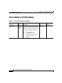
User Interface (UI) Parameter B-2
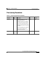
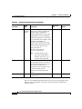
Provisioning Parameters B-3
Firmware Upgrade Parameters B-5
Operating Parameters B-7
APPENDIX
C
Audio Mode Parameters and Defaults C-1
APPENDIX
D
Dial Plan Parameters and Defaults D-1
About Programmable Dial Plans D-1
About Dial Plan Commands D-2
Example 1 D-3
Example 2 (Default Dial Plan) D-4
Dial Plan Blocking D-5
APPENDIX
E
Paid Services and Call Features Parameters and Defaults E-1
APPENDIX
F
Call Progress Tone Parameters and Defaults F-1
Call Progress Tone Parameters F-1
Cisco ATA 186 Installation and Configuration Guide
OL-1267-01
ix
Contents
Call Waiting and Alert Tone F-2
Playback Tone F-2
Notes F-3
Example -- Calculating The Volume Levels For Dial Tone F-3
Example Call Progress Tone Parameters F-4
APPENDIX
G
Call Commands G-1
Context Command Lists G-1
Syntax G-2
Context-Identifiers G-3
Action Identifiers G-4
Call Command Example G-5
Call Command Behaviors G-7
U.S. Call Command G-13
Configuring G-14
Sweden Call Command G-14
Configuring G-16
APPENDIX
H
Terms and Acronyms H-1
INDEX
Cisco ATA 186 Installation and Configuration Guide
x
OL-1267-01
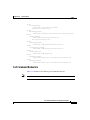
Preface
This preface describes:
•
Audience
•
Conventions used in this guide
•
Related documentation
•
How to access electronic documentation
Who Should Read This Guide
This guide is intended for service providers and network administrators who
administer network connectivity of the Cisco ATA 186 and use the
Cisco ATA 186 to provide voice over IP (VoIP) services to end users.
Note
For additional information about the SIP protocol with Cisco ATA, also refer
to the Cisco ATA 186 and Cisco ATA 188 Analog Telephone Adaptor
Administrator’s Guide (SIP).
Cisco ATA 186 Installation and Configuration Guide
OL-1267-01
xi
Preface
Related Documentation
Related Documentation
In addition to this Cisco ATA 186 Installation and Configuration Guide, the
Cisco ATA 186 documentation set includes the following:
•
Quick Start for the Cisco ATA 186 Analog Telephone Adaptor
•
Quick Reference Guide for the Cisco ATA 186 Analog Telephone Adaptor
•
Cisco ATA 186 Regulatory Compliance and Safety Information
•
Release Notes for Cisco ATA 186
Be sure to read any readme files or additional release notes for important
information.
Conventions
Table 1
Conventions
Convention
Description
boldface font
Commands and keywords.
italic font
Variables for which you supply values.
[
Keywords or arguments that appear within square brackets are optional.
]
{x | y | z}
A choice of required keywords appears in braces separated by vertical bars. You
must select one.
screen font
Examples of information displayed on the screen.
boldface screen
font
Examples of information you must enter.
<
>
Nonprinting characters, for example passwords, appear in angle brackets.
[
]
Default responses to system prompts appear in square brackets.
Cisco ATA 186 Installation and Configuration Guide
xii
OL-1267-01
Preface
Conventions
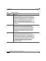
Table 1
Conventions (continued)
Convention
Description
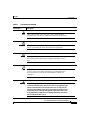
Note
This symbol means reader take note. Notes contain helpful
suggestions or references to additional information and material.
Timesaver
This symbol means the described action saves time. You can save
time by performing the action described in the paragraph.
Caution
This symbol means reader be careful. In this situation, you might
do something that could result in equipment damage or loss of
data.
Tips
This symbol means the following information will help you solve a
problem. The tips information might not be troubleshooting or
even an action, but could be useful information, similar to a
Timesaver.
Warning
This warning symbol means danger. You are in a situation that
could cause bodily injury. Before you work on any equipment, be
aware of the hazards involved with electrical circuitry and be
familiar with standard practices for preventing accidents. To see
translations of the warnings that appear in this publication, refer
to the Regulatory Compliance and Safety Information document
that accompanied this device.
Cisco ATA 186 Installation and Configuration Guide
OL-1267-01
xiii
Preface
Conventions
Table 1
Conventions (continued)
Convention
Waarschuwing
Description
Dit waarschuwingssymbool betekent gevaar. U verkeert in een
situatie die lichamelijk letsel kan veroorzaken. Voordat u aan
enige apparatuur gaat werken, dient u zich bewust te zijn van de
bij elektrische schakelingen betrokken risico's en dient u op de
hoogte te zijn van standaard maatregelen om ongelukken te
voorkomen. Voor vertalingen van de waarschuwingen die in deze
publicatie verschijnen, kunt u het document Regulatory
Compliance and Safety Information (Informatie over naleving van
veiligheids- en andere voorschriften) raadplegen dat bij dit toestel
is ingesloten.
Varoitus
Tämä varoitusmerkki merkitsee vaaraa. Olet tilanteessa, joka voi
johtaa ruumiinvammaan. Ennen kuin työskentelet minkään
laitteiston parissa, ota selvää sähkökytkentöihin liittyvistä
vaaroista ja tavanomaisista onnettomuuksien ehkäisykeinoista.
Tässä julkaisussa esiintyvien varoitusten käännökset löydät
laitteen mukana olevasta Regulatory Compliance and Safety
Information -kirjasesta (määräysten noudattaminen ja tietoa
turvallisuudesta).
Attention
Ce symbole d'avertissement indique un danger. Vous vous trouvez
dans une situation pouvant causer des blessures ou des
dommages corporels. Avant de travailler sur un équipement, soyez
conscient des dangers posés par les circuits électriques et
familiarisez-vous avec les procédures couramment utilisées pour
éviter les accidents. Pour prendre connaissance des traductions
d’avertissements figurant dans cette publication, consultez le
document Regulatory Compliance and Safety Information
(Conformité aux règlements et consignes de sécurité) qui
accompagne cet appareil.
Cisco ATA 186 Installation and Configuration Guide
xiv
OL-1267-01
Preface
Conventions
Table 1
Conventions (continued)
Convention
Warnung
Description
Dieses Warnsymbol bedeutet Gefahr. Sie befinden sich in einer
Situation, die zu einer Körperverletzung führen könnte. Bevor Sie
mit der Arbeit an irgendeinem Gerät beginnen, seien Sie sich der
mit elektrischen Stromkreisen verbundenen Gefahren und der
Standardpraktiken zur Vermeidung von Unfällen bewußt.
Übersetzungen der in dieser Veröffentlichung enthaltenen
Warnhinweise finden Sie im Dokument Regulatory Compliance
and Safety Information (Informationen zu behördlichen
Vorschriften und Sicherheit), das zusammen mit diesem Gerät
geliefert wurde.
Avvertenza
Questo simbolo di avvertenza indica un pericolo. La situazione
potrebbe causare infortuni alle persone. Prima di lavorare su
qualsiasi apparecchiatura, occorre conoscere i pericoli relativi ai
circuiti elettrici ed essere al corrente delle pratiche standard per
la prevenzione di incidenti. La traduzione delle avvertenze
riportate in questa pubblicazione si trova nel documento
Regulatory Compliance and Safety Information (Conformità alle
norme e informazioni sulla sicurezza) che accompagna questo
dispositivo.
Advarsel
Dette varselsymbolet betyr fare. Du befinner deg i en situasjon
som kan føre til personskade. Før du utfører arbeid på utstyr, må du
vare oppmerksom på de faremomentene som elektriske kretser
innebærer, samt gjøre deg kjent med vanlig praksis når det gjelder
å unngå ulykker. Hvis du vil se oversettelser av de advarslene som
finnes i denne publikasjonen, kan du se i dokumentet Regulatory
Compliance and Safety Information (Overholdelse av forskrifter og
sikkerhetsinformasjon) som ble levert med denne enheten.
Cisco ATA 186 Installation and Configuration Guide
OL-1267-01
xv
Preface
Obtaining Documentation
Table 1
Conventions (continued)
Convention
Aviso
Description
Este símbolo de aviso indica perigo. Encontra-se numa situação
que lhe poderá causar danos físicos. Antes de começar a trabalhar
com qualquer equipamento, familiarize-se com os perigos
relacionados com circuitos eléctricos, e com quaisquer práticas
comuns que possam prevenir possíveis acidentes. Para ver as
traduções dos avisos que constam desta publicação, consulte o
documento Regulatory Compliance and Safety Information
(Informação de Segurança e Disposições Reguladoras) que
acompanha este dispositivo.
¡Advertencia!
Este símbolo de aviso significa peligro. Existe riesgo para su
integridad física. Antes de manipular cualquier equipo,
considerar los riesgos que entraña la corriente eléctrica y
familiarizarse con los procedimientos estándar de prevención de
accidentes. Para ver una traducción de las advertencias que
aparecen en esta publicación, consultar el documento titulado
Regulatory Compliance and Safety Information (Información sobre
seguridad y conformidad con las disposiciones reglamentarias)
que se acompaña con este dispositivo.
Varning!
Denna varningssymbol signalerar fara. Du befinner dig i en
situation som kan leda till personskada. Innan du utför arbete på
någon utrustning måste du vara medveten om farorna med
elkretsar och känna till vanligt förfarande för att förebygga
skador. Se förklaringar av de varningar som förkommer i denna
publikation i dokumentet Regulatory Compliance and Safety
Information (Efterrättelse av föreskrifter och
säkerhetsinformation), vilket medföljer denna anordning.
Obtaining Documentation
The following sections provide sources for obtaining documentation from Cisco
Systems.
Cisco ATA 186 Installation and Configuration Guide
xvi
OL-1267-01
Preface
Obtaining Documentation
World Wide Web
You can access the most current Cisco documentation on the World Wide Web at
the following sites:
•
http://www.cisco.com
•
http://www-china.cisco.com
•
http://www-europe.cisco.com
Ordering Documentation
Cisco documentation is available in the following ways:
•
Registered Cisco Direct Customers can order Cisco Product documentation
from the Networking Products MarketPlace:
http://www.cisco.com/cgi-bin/order/order_root.pl
•
Registered Cisco.com users can order the Documentation CD-ROM through
the online Subscription Store:
http://www.cisco.com/go/subscription
•
Nonregistered Cisco.com users can order documentation through a local
account representative by calling Cisco corporate headquarters (California,
USA) at 408 526-7208 or, in North America, by calling 800
553-NETS(6387).
Documentation Feedback
If you are reading Cisco product documentation on the World Wide Web, you can
submit technical comments electronically. Click Feedback in the toolbar and
select Documentation. After you complete the form, click Submit to send it to
Cisco.
You can e-mail your comments to [email protected].
To submit your comments by mail, use the response card behind the front cover
of your document, or write to the following address:
Cisco ATA 186 Installation and Configuration Guide
OL-1267-01
xvii
Preface
Obtaining Technical Assistance
Attn Document Resource Connection
Cisco Systems, Inc.
170 West Tasman Drive
San Jose, CA 95134-9883
We appreciate your comments.
Obtaining Technical Assistance
Cisco provides Cisco.com as a starting point for all technical assistance.
Customers and partners can obtain documentation, troubleshooting tips, and
sample configurations from online tools. For Cisco.com registered users,
additional troubleshooting tools are available from the Technical Assistance
Center (TAC) website.
Cisco.com
Cisco.com is the foundation of a suite of interactive, networked services that
provides immediate, open access to Cisco information and resources at anytime,
from anywhere in the world. This highly integrated Internet application is a
powerful, easy-to-use tool for doing business with Cisco.
Cisco.com provides a broad range of features and services to help customers and
partners streamline business processes and improve productivity. Through
Cisco.com, you can find information about Cisco and our networking solutions,
services, and programs. In addition, you can resolve technical issues with online
technical support, download and test software packages, and order Cisco learning
materials and merchandise. Valuable online skill assessment, training, and
certification programs are also available.
Cisco ATA 186 Installation and Configuration Guide
xviii
OL-1267-01
Preface
Obtaining Technical Assistance
Customers and partners can self-register on Cisco.com to obtain additional
personalized information and services. Registered users can order products, check
on the status of an order, access technical support, and view benefits specific to
their relationships with Cisco.
To access Cisco.com, go to the following website:
http://www.cisco.com
Technical Assistance Center
The Cisco TAC website is available to all customers who need technical
assistance with a Cisco product or technology that is under warranty or covered
by a maintenance contract.
Contacting TAC by Using the Cisco TAC Website
If you have a priority level 3 (P3) or priority level 4 (P4) problem, contact TAC
by going to the TAC website:
http://www.cisco.com/tac
P3 and P4 level problems are defined as follows:
•
P3—Your network performance is degraded. Network functionality is
noticeably impaired, but most business operations continue.
•
P4—You need information or assistance on Cisco product capabilities,
product installation, or basic product configuration.
In each of the above cases, use the Cisco TAC website to quickly find answers to
your questions.
To register for Cisco.com, go to the following website:
http://www.cisco.com/register/
If you cannot resolve your technical issue by using the TAC online resources,
Cisco.com registered users can open a case online by using the TAC Case Open
tool at the following website:
http://www.cisco.com/tac/caseopen
Cisco ATA 186 Installation and Configuration Guide
OL-1267-01
xix
Preface
Product Disposal Warning
Contacting TAC by Telephone
If you have a priority level 1 (P1) or priority level 2 (P2) problem, contact TAC
by telephone and immediately open a case. To obtain a directory of toll-free
numbers for your country, go to the following website:
http://www.cisco.com/warp/public/687/Directory/DirTAC.shtml
P1 and P2 level problems are defined as follows:
•
P1—Your production network is down, causing a critical impact to business
operations if service is not restored quickly. No workaround is available.
•
P2—Your production network is severely degraded, affecting significant
aspects of your business operations. No workaround is available.
Product Disposal Warning
Warning
Waarschuwing
Varoitus
Ultimate disposal of this product should be handled according to
all national laws and regulations.
Het uiteindelijke wegruimen van dit product dient te geschieden
in overeenstemming met alle nationale wetten en reglementen.
Tämä tuote on hävitettävä kansallisten lakien ja määräysten
mukaisesti.
Attention
La mise au rebut ou le recyclage de ce produit sont généralement
soumis à des lois et/ou directives de respect de l'environnement.
Renseignez-vous auprès de l'organisme compétent.
Warnung
Die Entsorgung dieses Produkts sollte gemäß allen
Bestimmungen und Gesetzen des Landes erfolgen.
Avvertenza
Lo smaltimento di questo prodotto deve essere eseguito secondo
le leggi e regolazioni locali.
Cisco ATA 186 Installation and Configuration Guide
xx
OL-1267-01
Preface
Product Disposal Warning
Advarsel
Aviso
¡Advertencia!
Varning!
Endelig kassering av dette produktet skal være i henhold til alle
relevante nasjonale lover og bestemmelser.
Deitar fora este produto em conformidade com todas as leis e
regulamentos nacionais.
Al deshacerse por completo de este producto debe seguir todas
las leyes y reglamentos nacionales.
Vid deponering hanteras produkten enligt gällande lagar och
bestämmelser.
Cisco ATA 186 Installation and Configuration Guide
OL-1267-01
xxi
1
C H A P T E R
Cisco ATA 186 Overview
This chapter provides an overview of the Cisco ATA 186 Analog Telephone
Adaptor and describes the system features.
About the Cisco ATA 186
The Cisco ATA 186:
•
Is an Internet telephony appliance that converts any regular analog telephone
into an Internet telephone.
•
Converts voice into IP data packets that are sent over a network.
•
Is installed at the subscriber’s premises.
•
Supports two voice ports with their own telephone numbers.
•
Has one 10BaseT RJ-45 port and two RJ-11 FXS standard analog telephone
ports.
•
Supports both low-complexity voice codecs, such as G.711µ, G.711A-law,
and high-complexity/CELP codecs, such as G.723.1 and G.729A.
•
Can be configured to use either the H.323 or the SIP call signaling protocol.
•
Operates with Cisco Voice Packet Gateways.
•
Operates with H.323- or SIP-compliant Voice Packet Gateways.
Cisco ATA 186 Installation and Configuration Guide
OL-1267-01
1-1
Chapter 1
Cisco ATA 186 Overview
About the Cisco ATA 186
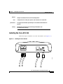
Hardware Features
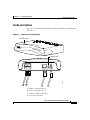
The Cisco ATA 186 features the hardware options listed in this section and shown
in Figure 1-1.
Figure 1-1
Features of the Cisco ATA 186
Function button
CISCO A
ANALOG
TA 186
TELEPH
ONE AD
APTOR
Indicator LED
A
PHONE 2
10BaseT
ACT
5V
62423
PHONE 1
B
C
D
A—Phone 1 connector (RJ-11)
B—Phone 2 connector (RJ-11)
C—10Base-T Ethernet connector
D—12V power connector
Cisco ATA 186 Installation and Configuration Guide
OL-1267-01
1-2
Chapter 1
Cisco ATA 186 Overview
About the Cisco ATA 186
•
Dual RJ-11 Ports
– Supports two independent RJ-11 telephone ports that can connect to any
standard analog telephone device. Each port supports either voice calls
or FAX sessions, so that the user can talk on one port while sending a
FAX on the other.
– There are two RJ-11 FXS port terminating impedance options, 600 Ohms
resistive or 270 Ohms + 750 Ohms // 150 nF complex impedance. The
impedance of the Cisco ATA 186 depends on the option ordered and
must match the particular application. If you are not sure of the
applicable configuration, check the country or regional telephone
impedance requirements.
•
Indicators
– Function Button
The Cisco ATA 186 function button is located in the top panel of the
device. The function button lights when you pick up the handset of a
telephone attached to the Cisco ATA 186. When the function button
blinks, the device is in configuration search or upgrade mode. You also
use the function button to access the interactive voice response (IVR)
configuration menu. To configure the Cisco ATA 186 by using the IVR
mode, see Chapter 3, “Configuring the Cisco ATA 186.”
– Activity LED
The green Activity LED located on the back panel flashes to indicate
network activity.
•
5 Volt power adapter connector (adapter included)
•
10Base-T Ethernet port
Additional Feature
Supports polarity reversal before and after caller-ID signal.
Cisco ATA 186 Installation and Configuration Guide
1-3
OL-1267-01
Chapter 1
Cisco ATA 186 Overview
About the Cisco ATA 186
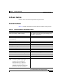
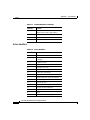
Software Features
Features of the Cisco ATA 186 depend on the protocol used.
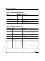
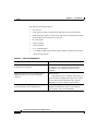
General Features
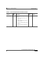
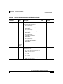
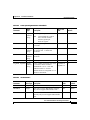
Table 1-1 includes information on features that are available for all protocols.
Table 1-1
Features Available for all Signaling Protocols
Description
Details
Basic provisioning (TFTP Profiling)
API, profile generation, client provisioning, RC4
encryption, and hard key
Call forwarding always from the Cisco ATA 186
Call forwarding on no answer from the
Cisco ATA 186
Call forwarding on busy from the Cisco ATA 186
Call waiting
Calling Line ID Presentation (CLIP)
Calling Line ID Rejection (CLIR)
Comfort noise generation (CNG)
Configurable ring specification
Dial Plan Support
Feature access code support
Domain Name Server (DNS) Lookup
DTMF Caller ID
On-hook only
Dynamic Jitter Buffering
Fax Detect/Passthrough
Note
G.711, Codec re-negotiation
Limited fax passthrough support is
available (up to 9.6 kbps fax
transmission rates for most fax
machines). Extended support is
planned. Please check release notes
and product bulletins for updates.
Cisco ATA 186 Installation and Configuration Guide
OL-1267-01
1-4
Chapter 1
Cisco ATA 186 Overview
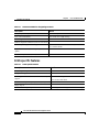
About the Cisco ATA 186
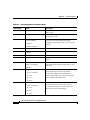
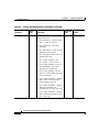
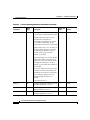
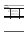
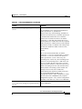
Table 1-1
Features Available for all Signaling Protocols
Description
Details
Frequency Shift Key (FSK) Caller ID
On-hook only
Line-echo cancellation
8 ms fixed echo length setting
Local ring-back tone
Remote diagnostics/monitor (trace of execution)
Three-way calling (conferencing)
The Cisco ATA 186 will automatically switch to
G.711 in this mode.
Type of Service (TOS) bit for Quality of Service
(QOS)
Voice activity detection (VAD)
H.323-specific Features
Table 1-2
H.323-specific Features
Description
Details
Alternate gatekeeper
Call proceeding
Cisco registration- and admission-level security
support
Uses MD5 hashing
Dual Tone Multiple Frequency (DTMF) relay
H.245
Uses access/clear token
Empty cap set
Fast start/tunneling/early H.245
Including H.245 messages in the Alert message
Cisco ATA 186 Installation and Configuration Guide
1-5
OL-1267-01
Chapter 1
Cisco ATA 186 Overview
About the Cisco ATA 186
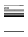
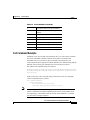
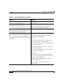
SIP Specific Features
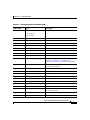
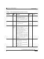
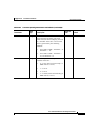
Table 1-3
SIP Features
Description
Details
Authentication
Digest Authentication
DTMF Relay
RFC 2833
Call Forwarding
Unconditionally, on no answer, or on busy
Call Return
Call Transfer
With or without consultation
Message Waiting Indication (MWI)
Plays an intermittent dial tone if there is a message
waiting. Otherwise, plays a normal dial tone.
Third-party call control
Cisco ATA 186 Installation and Configuration Guide
OL-1267-01
1-6
Chapter 1
Cisco ATA 186 Overview
About Supported Standards and Protocols
About Supported Standards and Protocols
The following standards are supported on the Cisco ATA 186:
•
Network interface: one RJ-45 8-wire connector, IEEE 802.3 10Base-T
standard
•
Two RJ-11 FXS standard analog telephone voice ports, up to 5 ringer
equivalency number (REN) per port, depending on loop length
•
ITU G.711µ, G.711A, G.723.1 Annex A, and G.729 Annex A voice codecs
•
G.723.1 Annex A, voice activity detection (VAD)/comfort noise generation
(CNG): bandwidth saving algorithm
•
ITU H.323 V.2 call signaling protocol
•
SIP: RFC 2543bis
•
LSSGR: Signaling for analog interfaces GR-506-CORE
•
RTP: real-time transmission Internet protocol
•
ITU-T V.42/V.42bis and MNP2-10 error correction and data compression
•
AVT Tones: RFC 2833
•
DHCP: RFC 2131
Cisco ATA 186 Installation and Configuration Guide
1-7
OL-1267-01
Chapter 1
Cisco ATA 186 Overview
About Supported Standards and Protocols
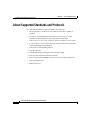
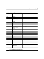
Electrical Specifications
Table 1-4
Electrical Specifications
Category
Specification
Voltage
+5.0 VDC at 1.5 A maximum
Power
0.25 to 7.5 Watts (idle, maximum)
Power adaptor
Universal AC/DC
3.3 x 2.0 x 1.3 in (~8.5 x 5.0 x 3.2 cm)
4.8 oz (135 gm) for the AC-input external power
adaptor
4 ft (1.2 m) DC cord
Class II transformer
6 ft (1.8 m) cord
UL/CUL, CE agency approvals
Environmental Specifications
Table 1-5
Environmental Specifications
Category
Specification
Operating Temperature
32° to 122° F (0 to 50° C)
Storage Temperature
-22° to 149° F (-30° to 65° C)
Relative Humidity
10 to 90% non-condensing, operating and storage
Cisco ATA 186 Installation and Configuration Guide
OL-1267-01
1-8
Chapter 1
Cisco ATA 186 Overview
About Supported Standards and Protocols
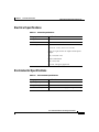
Standards Compliance
Table 1-6
Standards Compliance
Category
Specification
Agency approvals
UL/C-UL
FCC (Declaration of Conformity) Class B part 15 and part
68.
European Union, CE mark (Declaration of Conformity)
Industry Canada (Declaration of Conformity)
ACA (Declaration of Conformity)
VCCI (Declaration of Conformity)
Safety standards
UL60950
CAN/CSA-C22.2 No. 60950-00
IEC 60950 (Second Edition with Amendments 1, 2, 3, and
4)
EN60950:1992 (with Amendments 1, 2, 3, 4, and 11)
AS/NZS 3260:1993 (with Amendments 1, 2, 3, and 4)
TS001:1997
Cisco ATA 186 Installation and Configuration Guide
1-9
OL-1267-01
Chapter 1
Cisco ATA 186 Overview
About Supported Standards and Protocols
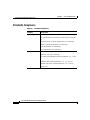
Table 1-6
Standards Compliance
Category
Specification
Emissions
CFR 47 Part 15 Class B 2000
EN55024, EN50082-1
EN55022/CISPR22 Class B
VCCI Class B
AS/NZS 3548:1995 Class B
ICES-003 (Issue 2, Class B, April 1997)
Immunity
EN50082-1 including the following
EN61000-3-2, Electromagnetic Compatibility
EN61000-3-3, Electromagnetic Compatibility
EN61000-4-2, ESD
EN61000-4-3, Radiated Immunity
EN61000-4-4, Burst Transients
EN61000-4-5, Surge
EN61000-4-6, Injected RF
EN61000-4-11, Dips and Sags
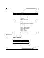
Dimensions
Table 1-7
Dimensions
Category
Specification
Length
6.5 in (16.5 cm)
Width
6 in (15.25 cm)
Height
1.5 in (3.8 cm)
Weight
15 oz (425 gm)
Cisco ATA 186 Installation and Configuration Guide
OL-1267-01
1-10
Chapter 1
Cisco ATA 186 Overview
About Supported Standards and Protocols
Cisco ATA 186 Installation and Configuration Guide
1-11
OL-1267-01
2
C H A P T E R
Installing the Cisco ATA 186
This chapter provides information about installing the Cisco ATA 186.
English is the default language. For information on the upgrade process, see
Chapter 6, “Upgrading the Cisco ATA 186 Software.”
Installation Overview
The general steps necessary to install the Cisco ATA 186 are:
1.
Plan the network and Cisco ATA 186 configuration.
2.
Install the Ethernet connection.
3.
Install and configure the other network devices; for example, gatekeeper if
you are using H.323 or proxy server if you are using SIP.
4.
If you will be routing calls through the Public Switched Telephone Network
(PSTN), install and configure the Gateway.
5.
Install the Cisco ATA 186.
6.
Configure the Cisco ATA 186.
7.
Perform any troubleshooting and maintenance, including upgrading the
software if necessary.
Cisco ATA 186 Installation and Configuration Guide
OL-1267-01
2-1
Chapter 2
Installing the Cisco ATA 186
Installation Overview
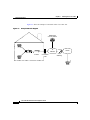
Figure 2-1 shows an example of a network with a Cisco ATA 186.
Figure 2-1
Example Network Diagram
Gatekeeper
or Proxy Server
PHONE 1
PHONE 2
10BaseT
ACT
IP
Network
5V
Broadband
modem
ISP
Connection
POP
PSTN
Voice
Gateway
62467
ATA 186
Cisco ATA 186 Installation and Configuration Guide
2-2
OL-1267-01
Chapter 2
Installing the Cisco ATA 186
Network Requirements
Network Requirements
The Cisco ATA 186 acts as a terminal on an IP network. You need the following
equipment:
•
One or two standard analog telephone handsets.
•
Ethernet connection.
•
Gatekeeper or proxy server—Currently, there must be a device running ITU
H.323 or RFC 2543bis SIP-complaint software. The gatekeeper must be
running the applicable version of software for the features and protocol you
want to use.
•
Voice Packet Gateway—Required if you are connecting to the Public
Switched Telephone Network (PSTN).
•
Fax machine (optional).
•
If you are using a firewall, Cisco recommends that it be a Cisco PIX firewall,
Version 5 or later versions.
Safety Recommendations
To ensure general safety, follow these guidelines:
•
Do not open or disassemble this product.
•
Do not get this product wet or pour liquids into this device.
•
Do not perform any action that creates a potential hazard to people or makes
the equipment unsafe.
Cisco ATA 186 Installation and Configuration Guide
OL-1267-01
2-3
Chapter 2
Installing the Cisco ATA 186
System Requirements
System Requirements
Caution
The Cisco ATA 186 is intended for use with a 5V DC power adaptor only.
The Cisco ATA 186 installation package includes:
•
Cisco ATA 186
•
Cisco ATA 186 documentation
•
5V Power Adaptor
You also need:
Note
•
10BaseT category-3 cable or better
•
One or two analog touch-tone telephones
Telephones must be set to use tone, rather than pulse dialing for the
Cisco ATA 186 to operate correctly.
Cisco ATA 186 Installation and Configuration Guide
2-4
OL-1267-01
Chapter 2
Installing the Cisco ATA 186
Installation Warnings
Installation Warnings
This section contains important safety information.
Number 26 AWG Warning
Warning
Waarschuwing
To reduce the risk of fire, use only No. 26 AWG or larger
telecommunication line cord.
Om brandgevaar te reduceren, dient slechts
telecommunicatielijnsnoer nr. 26 AWG of groter gebruikt te worden.
Varoitus
Tulipalovaaran vähentämiseksi käytä ainoastaan nro 26 AWG- tai
paksumpaa tietoliikennejohdinta.
Attention
Pour réduire le risque d’incendie, n’utiliser que des cordons de
lignes de télécommunications de type AWG nº 26 ou plus larges.
Warnung
Zur Reduzierung der Feuergefahr eine Fernmeldeleitungsschnur der
Größe 26 AWG oder größer verwenden.
Avvertenza
Advarsel
Aviso
¡Advertencia!
Varning!
Per ridurre il rischio di incendio, usare solo un cavo per linea di
telecomunicazioni di sezione 0,12 mm2 (26 AWG) o maggiore.
Bruk kun AWG nr. 26 eller telekommunikasjonsledninger med større
dimensjon for å redusere faren for brann.
Para reduzir o risco de incêndio, utilize apenas terminais de fio de
telecomunicações Nº. 26 AWG ou superiores.
Para reducir el riesgo de incendios, usar sólo líneas de
telecomunicaciones de calibre No. 26 AWG o más gruesas.
För att minska brandrisken skall endast Nr. 26 AWG eller större
telekommunikationsledning användas.
Cisco ATA 186 Installation and Configuration Guide
OL-1267-01
2-5
Chapter 2
Installing the Cisco ATA 186
Installation Warnings
Short-Circuit Protection Warning
Warning
Waarschuwing
This product relies on the building's installation for short-circuit
(overcurrent) protection. Ensure that a fuse or circuit breaker no
larger than 120VAC, 20A U.S. (240VAC, 16 to 20A international) is
used on the phase conductors (all current-carrying conductors).
The fuse or circuit breaker must have adequate safety approvals
recognized by the country of usage.
Dit product is afhankelijk van de installatie van het gebouw voor
bescherming tegen kortsluiting (overstroom). Zorg ervoor dat de
zekering of stroomonderbreker die gebruikt wordt niet groter is
dan 120 V~, 20 ampère in de V.S. of 240 V~, 16-20 ampère
internationaal op de fasegeleiders (alle stroomdragende
geleiders). De zekering of stroomonderbreker dient de juiste
veiligheidsgoedkeuringen te hebben in het land waarin het
gebruikt wordt.
Varoitus
Tämä tuote on riippuvainen rakennuksen oikosulkusuojauksesta
(ylivirtasuojauksesta). Varmista, että vaihejohtimissa (kaikissa
jännitteellisissä johtimissa) käytetään alle 240 V vaihtovirran,
16–20 ampeerin (kansainvälinen) tai 120 V vaihtovirran, 20
ampeerin (Yhdysvallat) sulaketta tai virtakytkintä. Sulakkeessa tai
virtakytkimessä on oltava käyttömaassa tunnistetut, riittävät
turvahyväksynnät.
Attention
Pour la protection contre les courts-circuits (surtension), ce
produit utilise les dispositifs intégrés au bâtiment. Assurez-vous
qu'un fusible ou un disjoncteur est utilisé sur les conducteurs de
phase (tous les conducteurs porteurs de courant). Le fusible ou le
disjoncteur (maximum 240 V CA, 16 à 20 A [aux USA, maximum 120
V CA, 20 A]) doit être conforme aux normes de sécurité en vigueur
dans votre pays.
Cisco ATA 186 Installation and Configuration Guide
2-6
OL-1267-01
Chapter 2
Installing the Cisco ATA 186
Installation Warnings
Warnung
Diese Produkt erfordert eine Gebäudeabsicherung gegen
Kurzschluß (Überstrom). Achten Sie darauf, daß auf den
Phasenleitern (allen stromführenden Leitern) eine Sicherung oder
ein Schaltkreisunterbrecher verwendet wird, der nicht größer ist
als 120VAC, 20A U.S. (240VAC, 16 bis 20A international). Die
Sicherung oder der Schaltkreisunterbrecher muß angemessenen
Sicherheitsvorschriften genügen, die den Bestimmungen des
Anwendungslandes entsprechen.
Avvertenza
La protezione di questo prodotto da cortocircuiti (sovracorrente)
dipende dall'impianto elettrico dell’edificio. Assicuratevi che un
fusibile o interruttore di circuito con meno di 120VAC, 20A U.S.
(240VAC, da 16 a 20A internazionale) venga utilizzato sui conduttori
di fase (tutti i conduttori di corrente elettrica). Il fusibile o
interruttore di circuito deve rispondere alle specifiche di
sicurezza invigore nel paese dove viene utilizzato.
Advarsel
Dette produktet er avhengig av bygningens installasjoner for
overstrømsbeskyttelse (kortslutning). Kontroller at det ikke brukes
en sikring eller overbelastningsbryter som er større enn 120 V, 20
ampere i USA, eller 240 V, 16 til 20 ampere internasjonalt, på
faselederne (alle strømførende ledere). Sikringen eller
overbelastningsbryteren må være sikkerhetsgodkjent i det
aktuelle landet der den skal brukes.
Aviso
Este dispositivo depende das instalações existentes para
protecção contra curto-circuitos (sobrecarga). Assegure-se de
que utiliza um fusível ou um disjuntor com uma capacidade não
superior a 120VAC, 20A U.S. (240VAC, 16 a 20A internacional) nos
condutores de fase (todos os condutores de corrente). O fusível ou
disjuntor deverá possuir as necessárias aprovações de segurança
por parte das autoridades locais.
Cisco ATA 186 Installation and Configuration Guide
OL-1267-01
2-7
Chapter 2
Installing the Cisco ATA 186
Installation Warnings
¡Advertencia!
Este producto ha sido diseñado teniendo en cuenta que la
instalación del edificio contará con protección contra
cortocircuitos (sobrevoltajes). Asegúrese de que se usa un fusible
o cortacircuitos no superior a 120VAC, 20A en los EE.UU. (240VAC,
de 16 a 20A en el resto de países) en los conductores de fase (todos
los conductores de transporte corriente). El fusible o
cortacircuitos debe contar con las aprobaciones de seguridad
adecuadas y reconocidas por el país en el que vayan a usarse.
Varning!
Denna produkt förlitar sig på att byggnadens installation är försedd
med skydd mot kortslutning (överström). Se till att en säkring eller
ett överspänningsskydd för högst 120 V~, 20 A USA (240 V~, 16 – 20
A internationellt) används på fasledarna (alla strömförande
ledare). Säkringen eller överspänningsskyddet måste ha fullgoda
säkerhetstillstånd som erkänns av användningslandet.
TN Power Systems Warning
Warning
Waarschuwing
The device is designed to work with TN power systems.
Het apparaat is ontworpen om te functioneren met TN
energiesystemen.
Varoitus
Koje on suunniteltu toimimaan TN-sähkövoimajärjestelmien
yhteydessä.
Attention
Ce dispositif a été conçu pour fonctionner avec des systèmes
d'alimentation TN.
Warnung
Das Gerät ist für die Verwendung mit TN-Stromsystemen ausgelegt.
Avvertenza
Il dispositivo è stato progettato per l’uso con sistemi di
alimentazione TN.
Cisco ATA 186 Installation and Configuration Guide
2-8
OL-1267-01
Chapter 2
Installing the Cisco ATA 186
Installation Warnings
Advarsel
Aviso
¡Advertencia!
Varning!
Utstyret er utfomet til bruk med TN-strømsystemer.
O dispositivo foi criado para operar com sistemas de corrente TN.
El equipo está diseñado para trabajar con sistemas de alimentación
tipo TN.
Enheten är konstruerad för användning tillsammans med
elkraftssystem av TN-typ.
Installing the Cisco ATA 186
Follow these steps to install the Cisco ATA 186 hardware. (See Figure 2-2.)
Figure 2-2
Installing the Cisco ATA 186
PHONE 2
10BaseT
ACT
5V
62290
PHONE 1
A
B
C
D
Cisco ATA 186 Installation and Configuration Guide
OL-1267-01
2-9
Chapter 2
Installing the Cisco ATA 186
Installation Warnings
A—Phone 1 connector (RJ-11)
B—Phone 2 connector (RJ-11)
C—10Base-T Ethernet connector
D—12V power connector
Step 1
Caution
Step 2
Note
Place the Cisco ATA 186 near an electrical outlet. Connect the first telephone to
the PHONE 1 input port (A) on the rear panel of the Cisco ATA 186 by using a
telephone line cord with an RJ-11 connector. The PHONE 1 input port will be the
primary telephone line.
Do not connect the Cisco ATA 186 PHONE input ports to the telephone wall
jack. To prevent damage to the device or building telephone wiring, connect
each Cisco ATA 186 PHONE port to a telephone only, never to a telephone
wall jack.
You can connect a second telephone to the PHONE 2 input (B) by using a second
telephone line cord. The PHONE 2 input is the secondary telephone line.
If you are connecting only one telephone to the Cisco ATA 186, you must use
the PHONE 1 input; otherwise, the telephone cannot place calls.
Step 3
Connect one end of a 10-BaseT Ethernet cable (C) to a hub, switch, or broadband
modem (DSL, cable, and so on).
Step 4
Connect the other end of the Ethernet cable to the RJ-45 input port (C) on the rear
panel of the Cisco ATA 186.
Note
Step 5
Use a crossover Ethernet cable to connect the Cisco ATA 186 to another
Ethernet device (such as a router or PC) without using a hub. Otherwise, use
a straight through Ethernet cable.
Plug the AC power adaptor into an electrical outlet. Insert the power cord into the
rear panel of the unit (D). Each connected telephone should ring once, indicating
that the Cisco ATA 186 is powered and ready to use. When the Cisco ATA 186 is
properly connected and powered up, the green activity LED flashes. The activity
LED, labeled ACT, indicates network activity.
Cisco ATA 186 Installation and Configuration Guide
2-10
OL-1267-01
Chapter 2
Installing the Cisco ATA 186
Installation Warnings
Caution
To prevent overheating during operation, do not cover or block the air vents
in the top panel of the Cisco ATA 186.
If installation was successful, proceed to Chapter 3, “Configuring the
Cisco ATA 186.”
Verifying the Installation
If the phone does not ring and the function button does not flash after power-up,
check that the power adaptor is plugged into a working electrical outlet and that
the power cord is pushed securely into the connector. Additionally, verify that the
Ethernet connection is secure.
Cisco ATA 186 Installation and Configuration Guide
OL-1267-01
2-11
Chapter 2
Installing the Cisco ATA 186
Installation Warnings
Cisco ATA 186 Installation and Configuration Guide
2-12
OL-1267-01
3
C H A P T E R
Configuring the Cisco ATA 186
This chapter provides information about configuring the Cisco ATA 186.
There are three ways to configure your Cisco ATA 186:
•
Voice Configuration Menu
•
Web browser
•
Autoprovisioning
Configuration Requirements
The Cisco ATA 186 requires the following minimum settings for network
connectivity:
• IP address
• Network route address (IP gateway)
• Subnet mask
Note
To enter an IP address, press the * key to indicate a delimiter (dot). For
example, 192*168*3*1. To hear the IP address of your Cisco ATA 186, after
your Cisco ATA 186 has been installed correctly, lift the telephone handset
and enter 21#.
Cisco ATA 186 Installation and Configuration Guide
OL-1267-01
3-1
Chapter 3
Configuring the Cisco ATA 186
About Using the Voice Configuration Menu
These settings are automatically configured in a DHCP network. When the
Cisco ATA 186 is downloading its DHCP configuration or software upgrade, the
function button on the top panel blinks.
Caution
Do not unplug the device while the function button is blinking. Doing so can
cause permanent damage to the device.
Note
If there is no DHCP server and the Cisco ATA 186 is programed to find one,
the function button will keep blinking.
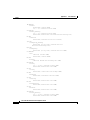
About Using the Voice Configuration Menu
Some IVR menu options will require you to enter alphanumerica characters.
Alphanumeric entry differs from numeric entry in that you must enter the # key
after each character selected. Using Table 3-1 as a guide, enter the appropriate
number key on your telephone handset as many times as needed to select the
number, letter, or symbol you want. For example, to enter 58sQ, you would enter:
5 # 8 # 7 7 7 7 7 # 7 7 7 7 7 7 7 # #
If you need to enter an alphanumeric value, the voice prompt will specifically tell
you to enter an alphanumeric value; otherwise, you should enter a numeric value
(0-9).
Cisco ATA 186 Installation and Configuration Guide
3-2
OL-1267-01
Chapter 3
Configuring the Cisco ATA 186
About Using the Voice Configuration Menu
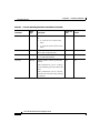
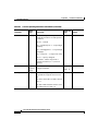
Table 3-1 lists the keys and their respective alphanumeric characters.
.
Table 3-1
Alphanumeric Characters
Key
Characters
1
1 ./_\ @@*space return +-!,?|~^ ##=$" '
``%<>[ ] ::;{}()&
2
2abcABC
3
3defDEF
4
4ghiGHI
5
5jklJKL
6
6mnoMNO
7
7pqrsPQRS
8
8tuvTUV
9
9wxyzWXYZ
0
0
*
. (delimeter)
The voice will repeat the value you entered; then, prompt you to press one of the
following keys:
•
1=change your entered value
•
2=review your entered value
•
3=save your entered value
•
4=review the current saved value
Cisco ATA 186 Installation and Configuration Guide
OL-1267-01
3-3
Chapter 3
Configuring the Cisco ATA 186
Using the Web Configuration Page
Using the Voice Configuration Menu
To manually configure the Cisco ATA 186 by using the interactive voice
response (IVR) system and telephone keypad, follow the steps in this section. For
a list of the available configuration options, see Appendix A, “Voice Menu
Options.”
Step 1
Lift the handset and press the Function button located on top of the
Cisco ATA 186.
Step 2
Enter the IVR menu number for the parameter that you want to configure or the
command that you want to execute; then, press the pound key (#). (See
Appendix A, “Voice Menu Options,” and Appendix B, “Parameters and
Defaults,” for lists of options and their corresponding menu numbers.)
Step 3
Follow the applicable prompts.
Step 4
When you have finished, make sure you press 3 to save your changes.
Step 5
Hang up the telephone. The Cisco ATA 186 resets.he function button will
fast-blink when the reset is complete.
Using the Web Configuration Page
You can configure your Cisco ATA 186 by using the web configuration page.
Each configurable parameter is listed, and parameters are grouped and
color-coded according to their function.
Caution
Cisco recommends you do not perform the initial configuration over the
Internet; the configuration page is not secure. After you have configured the
parameters, password-protect the user interface to prevent it from being
accessed on the Internet. The parameter for password-protecting this page is
UIPasswd.
Follow these steps:
Cisco ATA 186 Installation and Configuration Guide
3-4
OL-1267-01
Chapter 3
Configuring the Cisco ATA 186
About Autoprovisioning
Step 1
Make sure that the PC and the Cisco ATA 186 are already networked and visible
to one another.
Step 2
Open your web browser.
Step 3
Enter the URL of your configuration page. The URL of the web server is:
IP Address/dev
For example, the configuration page for a Cisco ATA 186 with the IP address
192.168.3.225 is:
http://192.168.3.225/dev
See “Using the Web Configuration Page” section on page 3-4 for information on
how to find the IP address of your Cisco ATA 186.
Step 4
Select the values for the items that you want to configure. (See Appendix B,
“Parameters and Defaults,” for a list of options.) Scroll down to see all
parameters. You can password-protect the user interface for security.
Step 5
Click apply to save your changes.
Step 6
Close your web browser.
About Autoprovisioning
For large-scale networks, you can use a TFTP server to host a profile for each
Cisco ATA 186. The TFTP server's URL and file name can be provided
(provisioned) from the DHCP server.
Set UseTFTP to 1.
TftpURL is the IP address of the TFTP server. If TftpURL is set to 0, the DHCP
server will supply the IP address.
Name the file to be downloaded according to the format:
ataxxxxxxxxxxxx
Each xx is the 2-digit lower case hexadecimal representation of each integer in the
MAC address of the Cisco ATA 186.
Cisco ATA 186 Installation and Configuration Guide
OL-1267-01
3-5
Chapter 3
Configuring the Cisco ATA 186
About Autoprovisioning
For example, for a Cisco ATA 186 with a MAC address of 0.1.45.2.10.20, the file
name is:
ata00012D020A14
The filename has a fixed length of 15 characters, regardless of the MAC address.
In this mode of provisioning, at power-up, the Cisco ATA 186 contacts the TFTP
server for a specific profile to download. The profile can be encrypted with a
shared secret key. If the Cisco ATA 186 does not reach the TFTP server after 3
attempts, it continues normal operation by using its locally cached profile.
Note
If the ToConfig value is set to 1, the Cisco ATA 186 will contact the TFTP
server continuously without waiting until the next CfgInterval. The value for
CfgInterval is the value of CfgInterval in seconds.
At CfgInterval, the Cisco ATA 186 attempts to refresh its profile from the TFTP
server.
You can configure the Cisco ATA 186 to refresh earlier than the scheduled
CfgInterval by opening a refresh web page on the Cisco ATA 186. The refresh
page is:
http://ipaddress/refresh
For example, for a Cisco ATA 186 whose IP address is 192.168.2.170, the refresh
page would be:
http://192.168.2.170/refresh
If you are using TFTP when the Cisco ATA 186 is plugged in, the Cisco ATA 186
will try to contact the TFTP server to download its configuration. This method is
not secure unless you are using EncryptKey. See the “Encrypt Key” section on
page 3-8.
cfgfmt.exe and ptag.dat Files
Bundled with the Cisco ATA 186 software is the program cfgfmt.exe and the file
ptag.dat. These should be placed the directory used to store the files for transfer
using TFTP. The cfgfmt program is used to convert a text-based user profile for
Cisco ATA 186 Installation and Configuration Guide
3-6
OL-1267-01
Chapter 3
Configuring the Cisco ATA 186
About Profile and Configuration Security
the Cisco ATA 186 to a binary file sent by the TFTP server to the Cisco ATA 186
to update its configuration parameters. The cfgfmt.exe program is used with the
following syntax:
cfgfmt [-eRC4Password] [-tPTagFile] input output
•
eRC4Password is the optional RC4 key to encrypt the binary TFTP file
provided by the cfgfmt program
•
tPTagFile is the optional command used to specify a ptag file other than the
one provided (ptag.dat)
•
input is the name of the text-based profile of the Cisco ATA 186 that will be
converted to a TFTP binary file
•
output is the name of the TFTP binary file produced by the cfgfmt program
Updating the Profile from the TFTP Server
To update the Cisco ATA 186 profile from the TFTP server before the
CFGINTERVAL expires, open your web browser and enter:
http://ipaddress/refresh
where ipaddress is the IP address of the Cisco ATA 186 you want to update. The
Cisco ATA 186 responds with an ok page if idle; otherwise, it responds with a
later page.
If you have physical access to the Cisco ATA 186, you can power cycle the
Cisco ATA 186 to update the profile from TFTP server.
About Profile and Configuration Security
This section includes information on passwords and other security methods.
Passwords
To password-protect your Cisco ATA 186:
Cisco ATA 186 Installation and Configuration Guide
OL-1267-01
3-7
Chapter 3
Configuring the Cisco ATA 186
About Using the DHCP Server
Step 1
Set the UIPassword parameter to a numeric password by using the web server
interface or TFTP profiling.
Step 2
You will be prompted for a password when you try to access the web server or a
configurable IVR parameter.
•
In web server mode, enter the password in the UIPassword field of the
password challenge page.
•
In IVR mode, enter the password, followed by the # key, at the p-a-s-s-w-d
prompt.
Encrypt Key
Encrypt Key encrypts binary files being transferred over TFTP. You can change
this key for each Cisco ATA 186, so that only one particular box can decode the
information. You can change the encrypt key, using the IVR or web interface.
See the “cfgfmt.exe and ptag.dat Files” section for more information.
The Cisco ATA 186 polls the server at intervals set in CfgInterval to see if it
needs to be upgraded. You can customize this service. For example, you can route
all calls from a particular Cisco ATA 186, based on the Gatekeeper ID, to an
operator.
About Using the DHCP Server
DHCP option 60, DHCP_VENDOR_CLASS_ID, is set to the value ATA186 so
that the DHCP server can identify a Cisco ATA 186.
Parameters that you can set using DHCP are:
•
Client IP address
•
Client Subnet mask—DHCP option 1
•
Routers on the client's subnet—DHCP option 3
•
Domain name servers—DHCP option 6
(The Cisco ATA 186 takes up to two DNS servers)
Cisco ATA 186 Installation and Configuration Guide
3-8
OL-1267-01
Chapter 3
Configuring the Cisco ATA 186
About Using the DHCP Server
•
Network time protocol (NTP) servers—DHCP option 42
(The Cisco ATA 186 takes up to two NTP servers)
•
TFTP server name—DHCP option 66
DNS, TFTP, and NTP servers can be overwritten by the value of the
corresponding parameters in the local box profile (for example, the DNS1IP,
DNS2IP, TftpURL, and NTPIP parameters).
If you are not using DHCP, you must manually enter the IP address, network route
address, and subnet mask.
Cisco ATA 186 Installation and Configuration Guide
OL-1267-01
3-9
Chapter 3
Configuring the Cisco ATA 186
Configuring Codec Options
Configuring Codec Options
You can configure the various Codec call options for use with the
Cisco ATA 186.
Note
The Cisco ATA 186 can support two simultaneous G.723 calls or one G.729A
call. When using G.729A, the second line must use G.711 u-law or a-law. The
default voice codec is G.723.
Step 1
To select G.723 as the preferred low-bit-rate codec (LBRCodec) for receive and
transmit modes, enter 0 into the LBCodec field on the web page. To select
G.729A, enter 3.
Step 2
To select G.723 as the preferred receive codec (RxCodec) enter 0 into the
RxCodec field on the web page. To select G.729A, enter 3.
Step 3
To select G.723 as the preferred transmit codec (TxCodec), enter 0 into the
TxCodec field on the web page. To select G.729A, press 3.
Cisco ATA 186 Installation and Configuration Guide
3-10
OL-1267-01
C H A P T E R
4
Protocol-Specific Configurations
This chapter contains information on selecting protocols and services for your
system.
About Signaling Protocols
You can select either H.323 or Session Initiation Protocol (SIP) as the operating
signaling protocol for the Cisco ATA 186. Both signaling protocols offer optional
network control servers. With H.323, pre-call and call control services are offered
by a gatekeeper, while in SIP, a proxy server can receive call transaction requests
and return responses on behalf of the Cisco ATA 186.
Some parameters and supplementary services are available with SIP, some are
available only with H.323, and others are available with both protocols.
About H.323-Specific Configurations
The Cisco ATA 186 uses ITU H.323, Version 2 as the default signaling protocol.
When operating in H.323 mode, the Cisco ATA 186 registers with a gatekeeper
to handle call control services. A full registration request (RRQ) is performed at
power-up. In order to let the gatekeeper know it is still on the network, the
Cisco ATA 186 periodically refreshes this registration by sending an abbreviated
RRQ. The value of the GKTimeToLive configuration parameter determines the
period between refreshes, in seconds.
Cisco ATA 186 Installation and Configuration Guide
OL-1267-01
4-1
Chapter 4
Protocol-Specific Configurations
About Gatekeeper Requirements for H.323
To use the H.323 security features, you must specify the level of authentication
by means of the AutMethod configuration parameter. The settings are as follows:
Note
•
0—no authentication
•
1—Cisco registration level
•
2—Cisco admission level
Make sure these levels are also enabled on the gatekeeper and gateway.
About Gatekeeper Requirements for H.323
The gatekeeper must meet these requirements:
Note
•
It must be H.323- or SIP-complaint.
•
It must run the applicable version of Cisco IOS software for the features and
protocol you want to use.
•
It must support H.323 or SIP, but only one at a time.
No specific configuration is required; configure the gatekeeper as you would
for any IP phone or Voice over IP (VoIP) configuration. The default
configuration is IP routing off.
Enabling IP Routing
To enable IP routing so that you can run Cisco IOS software, enter:
ip routing
Cisco ATA 186 Installation and Configuration Guide
4-2
OL-1267-01
Chapter 4
Protocol-Specific Configurations
About Gatekeeper Requirements for H.323
Connecting to a Network Time Protocol Server
If you want to use Caller ID (SIP) or security features (H.323), connect the
gateway to a functioning network time protocol (NTP) server. When using
Cisco IOS, enter:
ntp server ip_address
clock timezone PST -8
Note
For information on how to access accounting information, see your Cisco IOS
documentation.
Using ISDN/EI
If you are using ISDN, the requirements for E1 are:
ISDN switch-type primary-5ess
voice rtp send-rcv
Configuration depends on your WAN connection. The following example shows
a 24-channel PRI connected to a T1 VIC slot:
controller T1 0
framing esf
clock source linelinecode b8zs
pri-group timeslots 1-24
Cisco ATA 186 Installation and Configuration Guide
OL-1267-01
4-3
Chapter 4
Protocol-Specific Configurations
About Gatekeeper Requirements for H.323
Manipulating the Dial String
You can configure the Cisco ATA 186 to add digits to the beginning of the
outgoing dial string.
Note
The default for dial string manipulation is off.
Follow these steps to enable dial string manipulation by using prepending:
Step 1
From the web server interface, enter 4 in the Authenticate Method field.
Step 2
Enter the digits to be prepended in the associated PIN field.
For example, if you enter the dial string 5551212 in line 0 and the Cisco ATA 186
is configured with 1234 in the PWD0 field, the outgoing dial string is
12345551212.
Configuring Security Levels
Note
This is a Cisco Proprietary H.235 implementation; it uses the Cisco
access/clear token structure rather than the VocalTec crypto token structure.
To configure the Cisco ATA 186 to use Cisco Registration-Level Security (or
Admission-Level Security) in H.323 mode, follow these steps:
Step 1
Add AutMethod to match the web interface.
Step 2
Change the PIN globally to PWD.
Step 3
Set USELOGINID to 1. (0 indicates LOGINID0 and LOGINID1 fields are not
used; 1 indicates LOGINID0 and LOGINID1 fields are used for H.323
registration.)
Step 4
Set UID0 and UID1 to the correct E.164 IDs.
Step 5
Set LOGINID0 and LOGINID1 to the H.323 Login IDs.
Cisco ATA 186 Installation and Configuration Guide
4-4
OL-1267-01
Chapter 4
Protocol-Specific Configurations
About Alternate Gatekeepers and RAS
Step 6
Set PWD0 and PWD1 to the correct passwords/PINs (passwords for RADIUS
servers).
Step 7
Set AUTMETHOD to 1 or 2 (0 indicates no authentication; 1 indicates Cisco
Registration Level Security; 2 indicates Cisco Admission Level Security).
Step 8
If the DHCP server does not provide an IP address, set NTPIP to the NTP server
IP address.
About Alternate Gatekeepers and RAS
You can configure and accept acknowledgements from up to four Alternate
(backup) Gatekeepers (AltGK).
The Cisco ATA 186 allows you to configure an Alternate Gatekeeper as a backup
to the primary Gatekeeper. The Cisco ATA 186 can accept up to four dynamic
Alternate Gatekeepers configured by the H.225 RAS messages. It accepts both
temporary and permanent Alternate Gatekeepers.
When an Alternate Gatekeeper list is received with an H.225 RAS message, the
secondary Gatekeeper is merged and sorted with the dynamic Alternate
Gatekeepers. The secondary gatekeeper is kept and placed with the lowest
priority. To allow the Cisco ATA 186 to switch back to the primary gatekeeper
automatically, set a timeout value in seconds, AltGkTimeOut, to enable the
feature if non-zero value is used. The Cisco ATA 186 supports the Alternate
Gatekeeper list in the GCF/GRJ, ACF/ARJ, RCF/RRJ, and DRJ RAS messages.
See Appendix B, “Parameters and Defaults” for more information.
About SIP-Specific Configurations
The Session Initiation Protocol (SIP) is a text-based IETF-defined protocol for
establishing call sessions. To enable SIP on the Cisco ATA 186, you must set the
UseSIP configuration parameter to 1.
Session Description Protocol (SDP) is the part of the SIP message that establishes
parameters.
If you are using SIP, you must register with a proxy server. If you do not
remember the IP address, you can use the UserID, that is, the telephone number.
Cisco ATA 186 Installation and Configuration Guide
OL-1267-01
4-5
Chapter 4
Protocol-Specific Configurations
About Using a Proxy Server with SIP
About Using a Proxy Server with SIP
When using a Proxy Server, the Cisco ATA 186 sends a call to request a User ID
(telephone number). The proxy server holds a table of telephone numbers and
their equivalent IP addresses. You can enter this table manually (static), or the
Cisco ATA 186 can dynamically send the IP address to the proxy server when it
starts. This process is called Registration. To use this process, SIPRegOn must be
set to 1. The default is 0 or Off.
Registration has an expiration timeout, so the Cisco ATA 186 must periodically
resend its request. The interval is the number of seconds based on the value of
SIPRegInterval.
If OutboundProxy is enable all messages go through the IP address or URL listed.
The proxy routes to the end IP address.
About NAT Support with SIP
The following three parameters allow the Cisco ATA 186 to be used behind a
firewall or a network address translation (NAT) device to access a SIP proxy
server or user agent outside the firewall to register and make or receive calls. A
firewall or NAT device has a WAN IP address which is reachable from outside
the firewall, and a LAN IP address which is reachable from inside the firewall.
SIP Port
This is the logical UDP port where the device is listening for SIP messages. The
standard port number is 5060.
Note
Do not use reserved ports, such as 80 (HTTP).
To specify a port for the gatekeeper or proxy server, you can use either the IP
address or the URL. If no port is specified, the device uses the default of 5060.
If you want to specify a port with the IP address, use a dot (.):
123.10.10.10.5061
With a URL, use a colon (:):
www.company.com:5061
Cisco ATA 186 Installation and Configuration Guide
4-6
OL-1267-01
Chapter 4
Protocol-Specific Configurations
About NAT Support with SIP
MediaPort
The MediaPort configuration parameter specifies which base port the
Cisco ATA 186 uses to receive RTP media streams. This parameter is only used
for the purposes of SIP support behind a NAT.
NATIP
The NATIP configuration parameter specifies the WAN IP of the NAT. Specify
the LAN IP in the StaticRoute configuration parameter.
Cisco ATA 186 Installation and Configuration Guide
OL-1267-01
4-7
Chapter 4
Protocol-Specific Configurations
About NAT Support with SIP
Cisco ATA 186 Installation and Configuration Guide
4-8
OL-1267-01
C H A P T E R
5
Configuring Supplementary Services
This chapter includes information on supplementary services for the applicable
protocols. Supplementary services are services that you can use to enhance your
telephone service. The features must be enabled in:
•
Paid Services - the features your customers subscribe to.
•
Call Features - the services you are subscribed to. You can turn these features
on and off.
Changing Call Commands
To change the command for a supplementary service (for example, to change *69
to *100), change the context identifiers by changing the call command field in the
web browser on the provisioning page.
Note
You cannot change supplementary services by using the IVR, and you cannot
change timeout values.
Cancelling a Supplementary Service
Some features, such as call waiting, are disabled automatically when you hang up.
You can also deactivate them manually by pressing *70 before a call. In the case
of call waiting, the second caller hears a busy signal. You can also configure your
system to have the services disabled by default and enabled on a call-by-call basis.
This is done in the 32-bit “Call Features” plan.
Cisco ATA 186 Installation and Configuration Guide
OL-1267-01
5-1
Chapter 5
Configuring Supplementary Services
Common Supplementary Services
Common Supplementary Services
The supplementary services described in this section can be used with both the
H.323 and SIP signaling protocols. Available services and their configuration and
implementation depend on the country system you are using.
About 3-Way Calling (Conference Calling)
3-way calling works slightly differently on Swedish and U.S. systems.
Making a 3-Way Call in the U.S.
For U.S. configurations, follow these steps to make a conference call:
Step 1
Dial the first number.
Step 2
When the person you called answers, perform a “hook flash”; that is, hang up
quickly and pick up the phone quickly. This will put the first person you called on
hold and you will hear a dial tone.
Step 3
Dial the second person and speak normally when that person answers.
Step 4
To conference with both callers at the same time, perform a hook flash and press
3 on the telephone handset.
Step 5
To drop the second call, perform a hook flash.
Step 6
(Optional) To conference in additional callers, the last person called with a
Cisco ATA 186 can call an additional person, and so on. This is known as
“daisy-chaining.”
Making a 3-Way Call in Sweden
For Swedish configurations, follow these steps to make a conference call:
Step 1
Dial the first number.
Step 2
When the person you called answers, perform a “hook flash”; that is, hang up
quickly and pick up the phone quickly. This will put the first person you called on
hold and you will hear a dial tone.
Cisco ATA 186 Installation and Configuration Guide
5-2
OL-1267-01
Chapter 5
Configuring Supplementary Services
Common Supplementary Services
Step 3
Dial the second person and speak normally when that person answers.
Step 4
Perform a second hook flash and press 2 on the telephone handset to get back to
the first person. You can continue to switch back and forth between the two
callers.
Step 5
To conference with both callers at the same time, perform a hook flash and press
3 on the telephone handset. Once you conference all three callers, the only way to
drop a caller is for that caller to hang up.
Step 6
(Optional) To conference in additional callers, the last person called with a
Cisco ATA 186 can call an additional person, and so on. This is known as
“daisy-chaining.”
About Call Waiting
This section describes the Call Waiting feature.
Call Waiting in the U.S.
If someone calls you while you are speaking on the telephone, you can answer by
performing a hook flash. You cannot conference in all 3 callers, but the first
person you called could call someone else and “daisy-chain” them in. If there is
no answer after one minute, the caller will hear 3 beeps and a busy signal.
When the Cisco ATA 186 is configured to use Call Waiting by default, press *70
to disable Call Waiting for the duration of the next call.
Call Waiting in Sweden
If someone calls you while you are speaking on the telephone, you can answer by
performing a hook flash and pressing 2 to answer or 3 to conference them with
the person you are already speaking to. You can also press 3 later during the call
to conference.
Performing a hook flash and pressing 1 hangs up the first caller and answers the
second call. If there is no answer after one minute, the caller will hear 3 beeps and
a busy signal.
Cisco ATA 186 Installation and Configuration Guide
OL-1267-01
5-3
Chapter 5
Configuring Supplementary Services
Common Supplementary Services
To enable Call Waiting for Sweden, press *43#. When the Cisco ATA 186 is
configured to use Call Waiting by default, press #43# to disable Call Waiting for
the duration of the next call.
About Call Forwarding
In H.323, it is necessary to have a gatekeeper capable of handling call forwarding
and call return supplementary services. In SIP, the Cisco ATA 186 handles these
services.
There are 3 types of call forwarding.
•
Forward Unconditional—forwards every call that comes in.
•
Forward When Busy—forwards calls when the line is busy.
•
Forward on No Answer—forwards calls when the telephone is not answered
after the configured period of 0-63 seconds.
You can activate only one of these services at a time.
Forwarding Calls in the U.S.
Forward Unconditional
Press #72, the number you want to forward call to; then press # again.
Forward When Busy
Press #74, the number to forward the calls to; then press # again.
Forward On No Answer
Press #75, the number you want to forward the calls to; then press # again.
Cancelling Call Forwarding
To cancel call forwarding, press #73.
Cisco ATA 186 Installation and Configuration Guide
5-4
OL-1267-01
Chapter 5
Configuring Supplementary Services
Common Supplementary Services
Forwarding Calls in Sweden
Forward Unconditional
Press *21*v#, the number you want to forward call to; then press # again. To
cancel, press #21#.
Forward When Busy
Press *67*v#, the number to forward the calls to; then press # again. T0 cancel,
press #61#.
Forward On No Answer
Press *61*v#, the number you want to forward the calls to; then press # again. To
cancel, press #67#.
About Call Return
Call return allows you to call the last person who called you.
Returning Calls in the U.S.
Press *69 to activate Call Return.
Returning Calls in Sweden
Press *69# to activate Call Return.
About Calling Line Identification Presentation
Calling Line Identification Presentation (CLIP) shows your identity to callers
with Caller ID.
Calling Line Identification Presentation in the U.S.
Press *82 to activate CLIP.
Cisco ATA 186 Installation and Configuration Guide
OL-1267-01
5-5
Chapter 5
Configuring Supplementary Services
Common Supplementary Services
Calling Line Identification Presentation in Sweden
Calling Line Identification Presentation (CLIP) is not available for Sweden.
About Calling Line Identification Restriction
Calling Line Identification Restriction (CLIR) hides your identity from callers
with Caller ID.
Calling Line Identification Restriction in the U.S.
In the U.S., press *67 to activate CLIR. This feature is disabled when you hang
up.
Calling Line Identification Restriction in Sweden
In the U.S., press *31# to activate CLIR. This feature is disabled when you hang
up.
Cisco ATA 186 Installation and Configuration Guide
5-6
OL-1267-01
C H A P T E R
6
Upgrading the Cisco ATA 186
Software
You can upgrade the program of your Cisco ATA 186 remotely. Upgrades can be
done by using either of two methods:
Note
•
executable file
•
TFTP server
TFTP is case sensitive; if you use TFTP to upgrade your software, name your
files by using all lowercase letters.
Both methods require software available from cisco.com.
About Upgrading from Release 1.xx to Release 2.0
Caution
Release 2.0 is not backward-compatible with Release 1.xx.
Cisco ATA 186 Installation and Configuration Guide
OL-1267-01
6-1
Chapter 6
Upgrading the Cisco ATA 186 Software
About the Software Upgrade Process
Note
When upgrading from v1.34 to v2.0, the Cisco ATA 186 does not prompt the
user with the Upgrade Successful message when finished upgrading. Instead,
observe the function button LED. The LED will flash on and off during the
upgrade; then, change to a solid on state; then, turn off when the
Cisco ATA 186 has finished upgrading.
About the Software Upgrade Process
Note
The following information is optional detailed information about the upgrade
process.
The available options when using the software upgrade are:
ata186us -h[host_ip] -p[port] -quiet image file
•
-h[host_ip]—if the host has more than one IP address, use this option to set a
specific host IP address. The default is to use the first IP address obtained by
gethostbyname.
•
-p[port]—set the server port to specific port (default is 8000; use a different
port only if you are setting up an IP directed upgrade server other than the
default).
•
-quiet—set to quiet mode; that is, send all output to a log file named port.log.
This option is useful when the upgrade server is run as a daemon.
•
-any—allow upgrade even if the software version is older than or the same as
that of the client Cisco ATA 186.
•
-any2—allow upgrade regardless of software type and version.
•
-d1,-d2,-d3—set level of detailed description for debugging.
Example:
ata186us -h123.456.789.100 -p5786 -quiet yj2e112.kup yj2e112.el
Cisco ATA 186 Installation and Configuration Guide
6-2
OL-1267-01
Chapter 6
Upgrading the Cisco ATA 186 Software
About the Software Upgrade Process
Upgrading the Software by Using the Executable File
To upgrade your Cisco ATA 186 by using the ata186us.exe file and the voice
menu, you need the following:
•
A PC running Windows 9X/ME/NT/2000
•
A network connection between the PC and the Cisco ATA 186
To upgrade, follow these steps:
Step 1
In Windows, click Start > Programs > MSDOS Command Prompt and locate
or create a directory to store the file.
Step 2
After you unzip the files on the PC, save the executable file, the software image
(the software image will have a “.zup” extension) to a directory on your PC. The
images to save are:
•
ata186us.exe
•
ata186-vx.zup
where x is the version number and date of the software release; for example,
ata186-v2-00-0522b.zup.
Step 3
At the DOS prompt of the directory where the files are saved, enter:
ata186us software_file_name. zup -d1 -any2
Step 4
Press the function button to go to the configuration menu.
Caution
Step 5 will begin the upgrade process. Do not cancel the process or unplug the
power cord at any time during the upgrade process; doing so can permanently
damage your Cisco ATA 186. Wait until after the button stops flashing and the
light has turned off.
Step 5
Using the dialpad of your telephone attached to your Cisco ATA 186, enter:
100# ip_address_of_PC *8000#
For example, if the IP address of your PC is 192.168.1.10, enter:
100#192*168*1*10*8000#
Cisco ATA 186 Installation and Configuration Guide
OL-1267-01
6-3
Chapter 6
Upgrading the Cisco ATA 186 Software
About the Software Upgrade Process
Note
Press 123# to hear your code's version number.
You can later verify that you have upgraded your Cisco ATA 186.
Timesaver
When upgrading many Cisco ATA 186s, you can save the software upgrade
commands in your telephone’s speed-dial and use them after accessing the
Cisco ATA 186 voice menu.
Upgrading the Software from a TFTP Server
You can configure the Cisco ATA 186 to obtain its configuration from a TFTP
server. The configuration file (profile) is unique to each Cisco ATA 186 because
each profile name incorporates the unique MAC address associated with that
Cisco ATA 186. The profile can be configured to instruct the Cisco ATA 186 to
automatically upgrade its firmware image by using TFTP download without user
input.
The profile generation tool and example is available on the Cisco ATA 186
software download page of cisco.com.
To use the TFTP server to upgrade the Cisco ATA 186’s software, set the
UPGRADECODE (or UPGRADELANG if you are upgrading the language)
parameter in the Cisco ATA 186’s user profile to the following:
3,0x301,0x0400,0x0200,tftp_server_ip,69,n,filename_to_be_downloaded
•
tftp_server_ip is the TFTP server where you can download
file_name_to_be_downloaded
•
file_name_to_be_downloaded is the name of the TFTP upgrade method
firmware image
•
n is the software image release I.D. in the readme file that came with the
TFTP upgrade method firmware image.
Cisco ATA 186 Installation and Configuration Guide
6-4
OL-1267-01
Chapter 6
Upgrading the Cisco ATA 186 Software
About the Software Upgrade Process
Note
To help you identify the correct files to place on your TFTP server, the
TFTP-method file containing the Cisco ATA 186 software has a “.kxz”
extension.
Cisco ATA 186 Installation and Configuration Guide
OL-1267-01
6-5
Chapter 6
Upgrading the Cisco ATA 186 Software
About the Software Upgrade Process
Cisco ATA 186 Installation and Configuration Guide
6-6
OL-1267-01
C H A P T E R
7
Using the FAX Passthrough Feature
Both ports of the Cisco ATA 186 support FAX transmission. The Cisco ATA 186
can send FAXes by either of two methods:
•
FAX passthrough—In this mode, the Cisco ATA 186 can detect a FAX tone,
after which it will turn off FAX tone detection and silence suppression and
switch its operating codec to G.711 u-law or G.711 A-law.
•
G.711 FAX mode—In this mode, the Cisco ATA 186 simply passes the RTP
packets sent between the end FAX machines without any intervention. It
treats the FAX session like any normal voice call.
Note
Limited fax passthrough support is available (up to 9.6 kbps fax
transmission rates for most fax machines). Extended support is
planned. Please check release notes and product bulletins for updates.
Both the Cisco ATA 186 and the supporting gateway must be configured
appropriately to handle FAX signals.
About FAX Passthrough
To use the FAX passthrough feature, both the Cisco ATA 186 and the supporting
gateway must be configured at both ends to detect the FAX tone and switch codec.
The Cisco ATA 186 supports two G.711 upspeed methods for FAX passthorough:
•
The Cisco proprietary codec switch using NSE packets and RTP detection.
Cisco ATA 186 Installation and Configuration Guide
OL-1267-01
7-1
Chapter 7
Using the FAX Passthrough Feature
About Configuring the Cisco ATA 186 for FAX Passthrough
•
The standard-based protocol level (H.323/SIP) codec switch.
To interoperate with a Cisco gateway, which does not send protocol level codec
switch requests but can accept them, select the Cisco proprietary codec switch.
Note
When you are using G.729A on one port, the other port automatically uses the
G.711u-law or G.711A-law codec.
About Configuring the Cisco ATA 186 for FAX
Passthrough
There are two possible modes of configuration, ConnectMode and AudioMode.
ConnectMode
The ConnectMode bits in the Cisco ATA 186 configuration control the functions
described below. To interoperate with a Cisco gateway, Cisco recommends you
set the bits as follows:
•
Bit 7 (mask 0x80)—1 means enable FAX passthrough redundancy; 0 means
disable.
•
Bits 8-12 (mask 0x1F00)—Offset to NSE payload-type number 96. The
default value is 4 (as NSE payload-type number 100), and the valid values are
2 to 23 (98 to 119).
•
Bit 13 (mask 0x2000)—0 means use G.711u-law; 1 means using G.711A-law
as the new codec.
•
Bits 14, 15 (mask 0xC000)—Set as 00 to enable the FAX passthrough feature
using the Cisco proprietary method (recommended). Set as 11 to disable FAX
passthrough.
For example, a example, a *ConnectMode* setting of 0xXXXX040X means use NSE
payload-type number 100, G.711u-law codec, and no redundancy in FAX
passthrough mode.
AudioMode
Set to 0xXXXX0015 for line 1, or 0x0015XXXX for line 2, (X=don't care). This
setting enables FAX tone detection.
Cisco ATA 186 Installation and Configuration Guide
7-2
OL-1267-01
Chapter 7
Using the FAX Passthrough Feature
About Configuring the Cisco Gateway for FAX Passthrough
About Configuring the Cisco Gateway for FAX
Passthrough
The supporting Cisco gateway can enable FAX passthrough using system level or
dial-peer level commands.
System-Level Command
Enable the FAX passthrough feature using the system level commands:
voice service voip
modem passthrough NSE [payload-type number] codec {g711ulaw |
g711alaw} [redundancy] [maximum-sessions value]
•
The default payload-type parameter is 100. Valid values are 98 to 119. The
NSE payload number must be the same on both the Cisco ATA 186 and the
Cisco Gateway.
•
The codec must be G.711u-law for T1 or G.711A-law for E1.
•
The redundancy parameter enables RFC 2198 packet redundancy. It is
disabled by default.
•
The maximum sessions parameter defines the number of simultaneous FAX
Passthrough calls with redundancy. The default is 16; valid values are 1 to 26.
On the Cisco ATA 186, turn off bits 14 and 15 in ConnectMode. This enables
sending FAX passthrough signals and detection of incoming FAX passthrough
signals using the Cisco proprietary method.
The NSE payload-type number, FAX passthrough codec (G.711u-law or
G.711A-law) and redundancy must use the same settings in the Cisco ATA 186
and the supporting Cisco gateway.
Dial-Peer Level Command
The FAX passthrough feature can be enabled for communication between the
Cisco gateway and the specified Cisco ATA 186 using the dial-peer level
commands:
dial-peer voice tag voip
modem passthrough { NSE [payload-type number] codec {g711ulaw |
g711alaw} [redundancy] | system}
Cisco ATA 186 Installation and Configuration Guide
OL-1267-01
7-3
Chapter 7
Using the FAX Passthrough Feature
About FAX Mode
The default is:
modem passthrough system
When using the default (system) configuration, the dial-peer FAX passthrough
configuration is defined by the configuration in voice service voip. When system
is used, no other parameter is available.
When the NSE is configured in the FAX passthrough command in the dial-peer
level, the FAX passthrough definition in dial-peer takes priority over the
definition in voice service voip. The payload-type number, codec, and
redundancy parameters can also be used.
For example,
modem passthrough NSE codec g711ulaw
means use the NSE payload-type number 100, G.711ulaw, no redundancy in the
fax passthrough mode.
Disabling the FAX Passthrough Feature
To disable FAX passthrough, turn on bits 14 and 15 of the ConnectMode in the
Cisco ATA 186 configuration. On the Cisco gateway, enter:
no modem passthrough
About FAX Mode
Some users might want to set one or both lines of the Cisco ATA 186 to pure
G.711 FAX mode. This mode allows the FAX machine connected to the
Cisco ATA 186 to communicate directly with the FAX machine at the other end
of the call with no FAX signaling events between the two FAX machines.
Configuring the Cisco ATA 186 for FAX Mode
You can configure the Cisco ATA 186 to operate in FAX mode on one or both
lines.
Cisco ATA 186 Installation and Configuration Guide
7-4
OL-1267-01
Chapter 7
Using the FAX Passthrough Feature
About FAX Mode
The settings for FAX mode are:
•
AudioMode—Set to 0xXXXX0012 for line 1, or 0x0012XXXX for line 2,
(X = don't care). The value 0x0012 means we disable fax detection, disable
G.711 silence suppression and use G711 only on this line.
Configuring the Cisco ATA 186 for Fax Mode on a Per-Call Basis
If you want to activate Fax Mode on a per-call basis, configure bit 15
(line 1—mask 0x8000) and Bit 31 (line 2—mask 0x8000000)—0 (1) to set the
default to enable (disable) FAX mode on a per call basis.
To activate this call in the U.S., from the Fax machine enter *99 (default) and then
the telephone number to which you want to send the Fax. The next call will
automatically revert to normal mode.
To activate this call in Sweden., from the Fax machine enter *99# (default) and
then the telephone number to which you want to send the Fax. The next call will
automatically revert to normal mode.
Configuring the Cisco Gateway for FAX Mode
On the Cisco Gateway, disable both FAX relay and FAX Passthrough with the
following commands:
no fax relay
no modem passthrough
Cisco ATA 186 Installation and Configuration Guide
OL-1267-01
7-5
Chapter 7
Using the FAX Passthrough Feature
About FAX Mode
Cisco ATA 186 Installation and Configuration Guide
7-6
OL-1267-01
C H A P T E R
8
Testing and Troubleshooting the
Cisco ATA 186
This chapter describes how to test and troubleshoot the Cisco ATA 186.
Testing the Cisco ATA 186 Configuration
To test your Cisco ATA 186 configuration:
Step 1
Lift the primary line telephone handset.
Step 2
If you are not in SIP mode, enter your user ID (UID).
Step 3
If you hear a dial tone, your Cisco ATA 186 is properly configured.
Making a Call
Note
The dial plan described in these instructions is the default plan. You can
configure your Cisco ATA 186 to use a different plan.
Follow these steps to make a call:
Step 1
Lift the telephone handset.
Cisco ATA 186 Installation and Configuration Guide
OL-1267-01
8-1
Chapter 8
Testing and Troubleshooting the Cisco ATA 186
Troubleshooting Tips
Step 2
Tips
Dial as you normally do.
If you want to send the dial string out immediately, without waiting for the 2to 4-second timeout, press # after the last digit.
If the called party is available, you will hear ringing.
Step 3
When the called party answers, speak normally.
Step 4
Hang up when finished.
You can cancel or discontinue your call at any time by hanging up the handset.
You can make a separate, simultaneous telephone call by using the second
handset connected to the Cisco ATA 186. The Cisco ATA 186 can support two
simultaneous G.723 calls or one G.729A call. When using G.729A, the second
line must use G.711 u-law or a-law. The default voice codec is G.723.
Troubleshooting Tips
The suggestions in this section are general troubleshooting tips.
•
Make sure that you are correctly registered with the gatekeeper. Check to
make sure that you are using the correct gatekeeper IP address and the correct
E164 address for UID0 or UID1.
•
Check the green Network Activity LED to make sure that the network
connection is active.
•
Make sure that the DHCP server is operating correctly. Note that the Function
button flashes when the Cisco ATA 186 attempts to acquire the DHCP
configuration.
•
If you do not see the green activity LED flashing after you connect the
Ethernet cable, make sure the power cord and the Ethernet connection are
secure.
•
If you do not hear a dial tone, make sure that you have entered your user ID
(UID) and that the telephone line cord from the telephone is plugged into the
Cisco ATA 186 PHONE 1 port.
Cisco ATA 186 Installation and Configuration Guide
8-2
OL-1267-01
Chapter 8
Testing and Troubleshooting the Cisco ATA 186
Symptoms and Actions
•
A fast-busy tone indicates that the party you called is not available. Try your
call again later.
•
If you place a call to another IP telephone, hear ringing, and the called party
answers but you cannot hear the speaker’s voice, verify that the
Cisco ATA 186 and the other IP telephone support at least one common audio
codec technique: G.711A, G.711µ, G.723 and G.729A.
•
If you are using a firewall, make sure it is a Cisco PIX firewall, version 5 or
later versions.
•
After power up, if the function button continues to blink, indicating failure to
contact the DHCP server, check the Ethernet connection.
•
The DHCP server should show an incoming request from the MAC address
listed on the product label or given by the voice prompt.
•
If your system is configured to use a gatekeeper, a dial tone is heard after the
Cisco ATA 186 has been successfully registered with that gatekeeper. If you
do not hear a dial tone, check that all cables are connected properly and the
internet connections are operating correctly.
•
Make sure you do not have duplicate user IDs.
Symptoms and Actions
Symptom Parameters with values set by using the Web Server Interface or IVR
revert to their original settings.
Possible Cause You are using TFTP for provisioning (UseTFTP parameter is
set to 1). The Cisco ATA 186 has a cached value of its profile stored in its
flash ROM; this is what you will see or hear through the Web Server Interface
or IVR. If UseTFTP is set to 1, then the cached value of its profile is
synchronized with its profile located at the TFTP server. This synchronization
update of the cache value happens at approximate intervals determined by the
CFGInterval parameter's value or at power up reset.
Action If you are using TFTP for provisioning, do not use the Web Server
Interface or IVR to modify the value of your Cisco ATA 186 profile. Only use
the Web Server Interface or IVR to initially configure the Cisco ATA 186 to
use TFTP for provisioning.
Cisco ATA 186 Installation and Configuration Guide
OL-1267-01
8-3
Chapter 8
Testing and Troubleshooting the Cisco ATA 186
Symptoms and Actions
Symptom The Cisco ATA 186 does not appear to be provisioned by the TFTP
server.
Possible Cause The TftpURL is not correctly set to the URL or IP address of
the TFTP server that is hosting the profile for the Cisco ATA 186.
Action If you are using DHCP to supply the TFTP server IP address, make sure
that TftpURL is set to 0. Make sure that DNS1IP and DNS2IP are properly set
to resolve the TftpURL supplied by DHCP. (If the TftpURL supplied by
DHCP is an IP string, the Cisco ATA 186 does not need to consult with DNS.)
If you want to use DHCP server-assigned DNSes for resolving DNS requests,
make sure that DNS1IP and DNS2IP are set to 0.
Symptom The Cisco ATA 186 contacts the TFTP server more often than specified
in CFGINTERVAL.
Possible Cause The TOCONFIG parameter is not set to 0.
Action The TOCONFIG parameter set to 1 by default. This means that the
Cisco ATA 186 does not yet have a good operating profile. Once the
Cisco ATA 186 has a good operating profile, set the parameter to 0. This is
best done by including this parameter in the profile downloaded from the
TFTP server. If TOCONFIG is not set to 1, the Cisco ATA 186 tries to contact
the TFTP server more often than necessary.
Symptom There is no dial tone.
Possible Cause The Cisco ATA 186 has not successfully registered to the
gatekeeper or Proxy (GKORPROXY). If no GKORPROXY is specified, then
the Cisco ATA 186 is operating in pure IP to IP mode, and the Cisco ATA 186
can be addressed only by IP address.
Action Make sure that UID0 and UID1 are set to the applicable values
(telephone numbers) to get a dial tone on each line.
Cisco ATA 186 Installation and Configuration Guide
8-4
OL-1267-01
Chapter 8
Testing and Troubleshooting the Cisco ATA 186
Symptoms and Actions
Symptom Unable to access the web configuration page.
Possible Cause Software versions earlier than 2.0 require the web
configuration page to be enabled using option 80# on the IVR.
Action Upgrade the software.
Symptom FAX passthrough is not working or is working incorrectly.
Possible Cause By default, the VoIP dial-peers have FAX relay enabled on
them; when they hear the FAX training tone, they try to load the FAX relay
codec. The Cisco ATA 186 does not support this mechanism; it can only
support the passthrough mechanism.
Possible Cause Disable FAX relay on the VoIP dial-peers and enable the
passthrough mechanism.
Symptom IP Routing is not operating.
Possible Cause IP routing is off by default.
Action Enable IP routing on the gatekeeper by using the ip routing command.
See your Cisco IOS documentation for information.
Symptom Time is not displayed or is displayed incorrectly.
Possible Cause The Cisco ATA 186 and gatekeeper are not pointing to the
same network time protocol (NTP) server.
Action Make sure that both items are pointing to the same NTP server.
Symptom Cannot place call.
Possible Cause There may be a duplicate user ID.
Action Make sure that all user IDs are unique.
Cisco ATA 186 Installation and Configuration Guide
OL-1267-01
8-5
Chapter 8
Testing and Troubleshooting the Cisco ATA 186
Symptoms and Actions
Symptom The Cisco ATA 186 registration is rejected by the gatekeeper. The
gatekeeper contains more than one zone prefix command.
Possible Cause If delivering more than one zone prefix on the gatekeeper, the
UserID values or E.164 values on the H.323 endpoint (that is, the
Cisco ATA 186) must be within a defined zone prefix on the gatekeeper.
Action Add the zone prefixes in order for the Cisco ATA 186s to maintain
their registration.
Symptom Fast busy tone.
Possible Cause There may be a duplicate user ID.
Action Make sure that all user IDs are unique.
Symptom SIP parameters are not available.
Possible Cause The SIP protocol or SIP Registration are not enabled.
Action Make sure that you have enabled the SIP protocol by setting the UseSIP
parameter. If you are using proxy, enable SIP registration (for authentication).
Cisco ATA 186 Installation and Configuration Guide
8-6
OL-1267-01
Chapter 8
Testing and Troubleshooting the Cisco ATA 186
Installation and Upgrade Issues
Installation and Upgrade Issues
Note
The following issues apply to the manual upgrade process only. Image and
language upgrades must be performed separately.
Symptom The red LED is flashing.
Possible Cause The Cisco ATA 186 is trying to obtain the DHCP address or
the software image is being upgraded
Possible Cause The Ethernet cable is unplugged.
Action Plug in the Ethernet cable.
Symptom Voice prompt returns Upgrade not available message.
Possible Cause You are attempting to upgrade to the existing version.
Action There is no need to upgrade.
Symptom Voice prompt returns Upgrade failed message.
Possible Cause You have entered an incorrect IP address.
Action Enter the correct IP address.
Symptom No dial tone.
Possible Cause No user ID was entered.
Action Enter the correct user ID.
Cisco ATA 186 Installation and Configuration Guide
OL-1267-01
8-7
Chapter 8
Testing and Troubleshooting the Cisco ATA 186
Contacting TAC
Symptom Incorrect dial tone.
Possible Cause You installed a template for a country other than your own.
Check the web interface for your Dial Plan. The default is U.S.
Action Install the correct country template.
Mass Provisioning Issues
The following cautions apply during mass provisioning.
Caution
During upgrading, the function button flashes. Do not unplug the power
during this procedure.
Contacting TAC
If you need to contact the Cisco Technical Assistance Center (TAC), provide the
following information:
•
Product codes.
•
Software version number - To identify the software revision number, use the
configuration menu number—123.
•
Hardware version number - To identify the hardware revision number, use the
serial number and MAC address found on the label on the bottom of the
Cisco ATA 186.
•
Software build information - To identify the software build information, use
the voice menu option—123123.
•
Cisco ATA 186 serial number.
•
MAC address.
Cisco ATA 186 Installation and Configuration Guide
8-8
OL-1267-01
Chapter 8
Testing and Troubleshooting the Cisco ATA 186
Contacting TAC
Debugging
A debugging tool, prserv, is available from TAC. The pserv program is used in
conjunction with the NPrintf configuration parameter. Contact Cisco for more
information. See Obtaining Technical Assistance, page -xviii, for instructions.
Debug commands that you can use on your Cisco IOS are
debug RAS
and
debug H225 ASN1
You should also have access to a “sniffer” or LAN analyzer.
Caution
For security reasons, Cisco recommends that you do not use the web interface
over the public network. Disable the web interface by using the UIPassword
parameter before the Cisco ATA 186 leaves the service provider site.
Cisco ATA 186 Installation and Configuration Guide
OL-1267-01
8-9
Chapter 8
Testing and Troubleshooting the Cisco ATA 186
Contacting TAC
Cisco ATA 186 Installation and Configuration Guide
8-10
OL-1267-01
A P P E N D I X
A
Voice Menu Options
This Appendix contains a list of the Voice Menu options for the Cisco ATA 186.
Note
Table A-1
Press # after you enter the item number.
Voice Menu Options in Alphabetical Order
Option
Item Number
Description
Alternate Gatekeeper (Altgk)
6
(H.323)
Alternate Gatekeeper Timeout
251
(H.323)
Alternate NTP IP Address
78
Audio Mode
312
Authenticate Method
92
(H.323)
Build Information
123123
Listen to the build date of the Cisco ATA 186
software
Call Features
314
Call Wait Caller ID
317
Caller ID Method
316
CfgInterval
80002
Connect Mode
311
Not currently available
Cisco ATA 186 Installation and Configuration Guide
OL-1267-01
A-1
Appendix A
Table A-1
Voice Menu Options
Voice Menu Options in Alphabetical Order
Option
Item Number
Description
Dynamic Host Configuration
Protocol (DHCP)
20
This command controls whether the
Cisco ATA 186 can automatically obtain
configuration parameters from a server over the
network.
0=Disable
1=Enable (Default)
Diagnostic Information
411
DNS 1 IP
916
DNS 2 IP
917
Encrypt Key
320
Num Tx Frames
35
Select the number of frames per packet to be
transmitted when using the audio codec G.723.1
or G.729A.
Gatekeeper ID
91
(H.323)
Gatekeeper/Proxy Server IP
Address
5
Enter the gatekeeper or proxy server IP address.
Gatekeeper time to live
250
(H.323) Enter the amount of idle time before the
gatekeeper times out.
Gateway IP Address
11
(H.323) Enter the IP address of the gateway. This
number can be automatically assigned when
DHCP is enabled.
IP Address
1
Enter the IP address of the Cisco ATA 186. This
number can be automatically assigned when
DHCP is enabled.
IP Dial Plan
310
LBR Codec
300
Login ID 0
46
Login ID 1
47
Media port
202
(SIP)
Network Route Address
2
Enter the network route address. This number can
be automatically assigned when DHCP is enabled.
Values: 1 through 12
Default=2
Cisco ATA 186 Installation and Configuration Guide
A-2
OL-1267-01
Appendix A
Table A-1
Voice Menu Options
Voice Menu Options in Alphabetical Order
Option
Item Number
NPrintf Address
81
NTP Server Address
141
Paid Features
315
Polarity
304
PWD 0
4
Enter the password associated with the gateway
account.
PWD 1
14
Enter the password associated with the second
gateway account.
Review IP Address
21
Listen to the IP address.
Review MAC Address
24
Listen to the media access control (MAC) address.
Review Network Route IP
Address
22
Listen to the IP address of the network route.
Review Subnet Mask
23
Listen to the subnet mask.
Rx Codec
36
Select the audio codec type to use to decode
received data. The call-receiving station
automatically adjusts to the call-initiating station's
audio codec type if the call-receiving station
supports that audio codec.
0=G.723.1 (default)
1=G.711A
2=G.711µ
Description
3=G.729A
Set Password
7387277
SigTimer
318
SIP Max Number of Redirects
205
(SIP)
SIP NAT IP Address
200
(SIP)
SIP Outbound Proxy
206
(SIP)
SIP Port
201
(SIP)
SIP Protocol
38
Select the signalling protocol.
0=Select H.323
1=Select SIP
Cisco ATA 186 Installation and Configuration Guide
OL-1267-01
A-3
Appendix A
Table A-1
Voice Menu Options
Voice Menu Options in Alphabetical Order
Option
Item Number
Description
SIP Registration On
204
(SIP)
SIP Registration Period
203
(SIP)
Subnet Mask
10
Enter the subnet mask. This number can be
automatically assigned when DHCP is enabled.
The default is 255.255.255.0.
TFTP URL
905
Timezone
302
ToConfig
80001
See Appendix B, “Parameters and Defaults”
313
Enable logging of SIP messages.
37
Select the audio codec type to use to encode data
for transmission. The audio codec type for
receiving does not have to be the same as the audio
codec type for transmitting.
0=provisioned
1=new (default)
Trace Flags
0=disable (default)
1=enable
Tx Codec
0=G.723.1 (default)
1=G.711A
2=G.711µ
3=G.729A
UDP TOS Bits
255
UID 1
13
Upgrade Software
100
Upgrade Language to English
101
Use Login ID
93
Enter the User ID (telephone number) for the
Phone 2 port.
Change or upgrade the voice prompt language to
English. See Chapter 6, “Upgrading the
Cisco ATA 186 Software” for more information.
Cisco ATA 186 Installation and Configuration Guide
A-4
OL-1267-01
Appendix A
Table A-1
Voice Menu Options
Voice Menu Options in Alphabetical Order
Option
Item Number
Use TFTP
305
Description
0=disable (default)
1=enable
UID 0
3
Enter the User ID (telephone number) for the
Phone 1 port.
Version Number
123
Listen to the version number of the
Cisco ATA 186 software.
Table A-2
Voice Menu Options in Numerical Order
Item Number
Option
Description
1
IP Address
Enter the IP address. This number can be
automatically assigned when DHCP is enabled.
2
Network Route Address
Enter the network route address. This number can
be automatically assigned when DHCP is enabled.
3
UID 0
Enter the User ID (telephone number) for the
Phone 1 port.
4
PWD 0
Enter the password associated with the gateway
account.
5
Gatekeeper/Proxy Server IP
Address
Enter the gatekeeper or proxy server IP address.
6
Alternate Gatekeeper (Altgk)
(H.323)
10
Subnet Mask
Enter the subnet mask. This number can be
automatically assigned when DHCP is enabled.
The default is 255.255.255.0.
11
Gateway IP Address
Enter the IP address of the gateway. This number
can be automatically assigned when DHCP is
enabled.
Cisco ATA 186 Installation and Configuration Guide
OL-1267-01
A-5
Appendix A
Table A-2
Voice Menu Options
Voice Menu Options in Numerical Order
Item Number
Option
Description
13
UID 1
Enter the User ID (telephone number) for the
Phone 2 port.
14
PWD 1
Enter the password associated with the second
gatekeeper account.
20
Dynamic Host Configuration
Protocol (DHCP)
This command controls whether the
Cisco ATA 186 can automatically obtain
configuration parameters from a server over the
network.
0=Disable
1=Enable (Default)
21
Review IP Address
Listen to the IP address.
22
Review Network Route IP
Address
Listen to the IP address of the network route.
23
Review Subnet Mask
Listen to the subnet mask.
24
Review MAC Address
Listen to the media access control (MAC)
address.
35
Num Tx Frames
Select the number of frames per packet to be
transmitted when using the audio codec G.723.1
or G.729A.
Values: 1 through 12.
Default=2
36
Rx Codec
0=G.723.1 (default)
1=G.711A
2=G.711µ
Select the audio codec type to use to decode
received data. The call-receiving station
automatically adjusts to the call-initiating
station's audio codec type if the call-receiving
station supports that audio codec.
3=G.729A
37
Tx Codec
0=G.723.1 (default)
1=G.711A
Select the audio codec type to use to encode data
for transmission. The audio codec type for
receiving does not have to be the same as the
audio codec type for transmitting.
2=G.711µ
3=G.729A
Cisco ATA 186 Installation and Configuration Guide
A-6
OL-1267-01
Appendix A
Table A-2
Voice Menu Options
Voice Menu Options in Numerical Order
Item Number
Option
Description
38
SIP Protocol
Select the signalling protocol.
0=Select H.323
1=Select SIP
46
Login ID 0
47
Login ID 1
78
Alternate NTP IP Address
81
NPrintf Address
91
Gatekeeper ID
(H.323)
92
Authenticate Method
(H.323)
93
Use Login ID
100
Upgrade Software
101
Upgrade Language to English
Change or upgrade the voice prompt language to
English. See Chapter 6, “Upgrading the
Cisco ATA 186 Software” for more information.
123
Version Number
Listen to the version number of the
Cisco ATA 186 software.
141
NTP Server Address
200
SIP IP Proxy Address
(SIP)
201
SIP Eproxy Address
(SIP)
202
Media port
(SIP)
203
SIP Registration Period
(SIP)
204
SIP Registration On
(SIP)
205
SIP Max Number of Redirects (SIP)
206
SIP Outbound Proxy
(SIP)
250
Gatekeeper time to live
(H.323) Enter the amount of idle time before the
gatekeeper times out.
251
Alternate Gatekeeper timeout
(H.323)
255
UDP TOS Bits
Cisco ATA 186 Installation and Configuration Guide
OL-1267-01
A-7
Appendix A
Table A-2
Voice Menu Options
Voice Menu Options in Numerical Order
Item Number
Option
300
LBR Codec
302
Timezone
304
Polarity
305
Use TFTP
Description
0=disable (default)
1=enable
310
IP Dial Plan
311
Connect Mode
312
Audio Mode
313
Trace Flags
Enable logging of SIP messages
0=disable (default)
1=enable
314
Call Features
315
Paid Features
316
Caller ID Method
317
Call Wait Caller ID
318
SigTimer
320
Encrypt Key
411
Diagnostic Information
905
TFTP URL
916
DNS 1 IP
917
DNS 2 IP
123123
Build Information
Listen to the build date of the Cisco ATA 186
software
80001
ToConfig
See Appendix B, “Parameters and Defaults”
Not currently available
0=provisioned
1=new (default)
Cisco ATA 186 Installation and Configuration Guide
A-8
OL-1267-01
Appendix A
Table A-2
Voice Menu Options
Voice Menu Options in Numerical Order
Item Number
Option
80002
CfgInterval
7387277
Set Password
Description
Cisco ATA 186 Installation and Configuration Guide
OL-1267-01
A-9
Appendix A
Voice Menu Options
Cisco ATA 186 Installation and Configuration Guide
A-10
OL-1267-01
A P P E N D I X
B
Parameters and Defaults
This Appendix provides information on the parameters and defaults that you can
use to provision your Cisco ATA 186.
Provisioning files must begin with #txt for the formating tool, cfgfmt.exe, to treat
it as text file.
Begin at new line indicates a comment.
All parameter/value pairs are optional but might be needed for the
Cisco ATA 186 to function properly if a value has not already been programmed.
Where an IVR Access Code is available, you can use either the alphanumeric
entry method or a numeric entry method to specify the value of the parameter
using an IVR alternate interface. Convert the hexadecimal value to decimal when
using the IVR alternate interface (numeric entry method) before you manually
enter the value by using IVR.
Parameter values can be one of the following types:
•
alphanumeric string
•
numeric digit string
•
array of short integer
•
IP address (e.g. 192.168.2.170)
•
Extended IP address—IP address with Port (for example,
192.168.2.170.9001)
•
boolean (1 or 0)
•
bitmap value—unsigned hex integer (for specifying bits in 32-bit integer)
•
integer (32 bit integer).
Cisco ATA 186 Installation and Configuration Guide
OL-1267-01
B-1
Appendix B
Parameters and Defaults
User Interface (UI) Parameter
User Interface (UI) Parameter
Table B-1
User Interface Parameter and Default
Parameter
UIPassword
Value
Type
Alphanumeric
string
Description
IVR Access
Code
7387277
Control access to web page or IVR
interface. If set to non-zero, then you
must enter the value of UIPassword
to access the web page and IVR.
Note
Default
0
When UIPassword
contains letters, you
cannot enter the password
from the telephone
keypad.
Cisco ATA 186 Installation and Configuration Guide
B-2
OL-1267-01
Appendix B
Parameters and Defaults
Provisioning Parameters
Provisioning Parameters
Table B-2
TFTP Provisioning Parameters and Defaults
Parameter
Value
Type
IVR Access
Code
Description
80002
Specifies the number of seconds
(interval) between each
configuration update. For example,
when using TFTP for provisioning,
the Cisco ATA 186 contacts TFTP
each time the interval expires to get
its configuration file the next time the
box is idle.
CfgInterval
Default
3600
You can set CfgInterval to a random
value to achieve random contact
intervals from individual
Cisco ATA 186 to the TFTP server.
EncryptKey
Alphanumeric
string
320
0
Cisco ATA 186 Installation and Configuration Guide
OL-1267-01
B-3
Appendix B
Parameters and Defaults
Provisioning Parameters
Table B-2
Parameter
TftpURL
TFTP Provisioning Parameters and Defaults
Value
Type
Alphanumeric
string
Description
IVR Access
Code
905
IP address or URL of the TFTP
server to use. This is needed if the
Dynamic Host Configuration
Protocol (DHCP) does not give the
TFTP address. You can optionally
include the path prefix to the TFTP
file to download. For example, if the
TFTP server IP address is
192.168.2.170 or www.cisco.com,
and the path to download the TFTP
file is in /ata186, then you can
specify the URL as
192.168.2.170/ata186 or
www.cisco.com/ata186.
Note
Default
0
From the IVR, you can
only enter the IP address;
from the web server, you
can enter the actual URL.
ToConfig
Boolean
The default is 1. This indicates that
the operating parameters of the box
have not previously been set. Once
the Cisco ATA 186 has been
provisioned, set the parameter to 0,
or the Cisco ATA 186 will
unnecessarily contact the TFTP
server.
80001
0
UseTFTP
Boolean
1 means use TFTP for provisioning;
0 means do not.
305
1
There are two additional parameters that are used to control the upgrade of the
firmware code and language. The values of these parameters depend on the
software release.
Cisco ATA 186 Installation and Configuration Guide
B-4
OL-1267-01
Appendix B
Parameters and Defaults
Firmware Upgrade Parameters
Firmware Upgrade Parameters
The upgradecode and upgradelang parameters are special parameters that provide
information on how to upgrade firmware code or language image.
The values are:
•
upgrade_policy
•
hardware_version
•
software_type
•
software_version
•
tftp_ip_address
•
tftp_port
•
image_id
•
firmware_image_file_name
All values must be present. Except for upgrade_policy field, Cisco supplies the
values to be used when a new upgrade image becomes available
The values are:
•
upgrade_policy—one of the following:
– default upgrade— software_type must be the same as the current
Cisco ATA 186. Internal software_type and software_version must be
greater than the current internal software_version for the upgrade to take
place.
– cross software type upgrade—the software_type can be different but
software_version must be greater than the current firmware internal
version.
– force upgrade—the image_id is used to determine if the upgrade has been
performed (a different image ID from the Cisco ATA 186 internally
stored image ID means a forced upgrade is needed).
•
hardware_version— 0x301. The hardware version must match exactly for
upgrade to take place.
•
tftp_ip_address, tftp_port—TFTP IP and port address where the firmware
can be found.
Cisco ATA 186 Installation and Configuration Guide
OL-1267-01
B-5
Appendix B
Parameters and Defaults
Firmware Upgrade Parameters
•
image_id—used for force upgrade to determine if an upgrade had taken place
previously.
•
firmware_image_file_name—firmware image file name.
– For example,
upgradecode:1,0x301,0x0400,0x0200,192.168.2.170,69,0x1,
ef2_200h.kxz
– upgradelang:1,0x301,0x0400,0x0200,192.168.2.170,69,0x1,ef2e200h.kbx
– The default values listed below will not trigger any upgrade.
upgradecode:0,0x301,0x0400,0x0200,0.0.0.0,69,0,none
upgradelang:0,0x301,0x0400,0x0200,0.0.0.0,69,0,none
Example:
1,0x031,0x0400,0x0200,192.168.2.170,69,0x1,ef2_200h.kxz
1= upgrade policy
0x031=hardware version
0x0400=software type
0x0200=software version
192.168.2.170=tftp_ip_address
69=TFTP port
0x1=image id
ef2_200h.kxz=firmware image file name
Cisco ATA 186 Installation and Configuration Guide
B-6
OL-1267-01
Appendix B
Parameters and Defaults
Operating Parameters
Operating Parameters
Table B-3
Common Operating Parameters and Defaults
Parameter
Value
Type
AutMethod
Bitmap
CallCmd
Alphanumeric
string
IVR Access
Code
Default
Description
Authentication method. Possible values 92
are:
•
bit 0-1 (mask 0x3): 0 for no
authentication, 1 for authentication
•
Cisco registration level security
(H.235), 2 for Cisco Systems
admission level security.
•
bit 2 (mask 0x4): prefix password
field when registering.
N/A
Controls call commands such as
turning on and off Caller ID and so on.
(248 characters maximum.)
0x00000000
U.S. Cmd
Table
U.S. Cmd Table
CallCmd:Af;AH;BS;NA;CS;NA;Df;E
B;Ff;EP;Kf;EFh;HQ;Jf;AFh;HQ;I*67;
gA*82;fA90v;OI;H72v;bA74v;cA75v;
dA73;eA*67;gA*82;fA*70;iA*69;DA
*99;xA;Uh;GQ;
Swedish Cmd Table
CallCmd:BS;NA;CS;NA;Df;EB;Ff0;A
Rf1;HPf2;EPf3;AP;Kf1;HFf2;EFf3;A
Ff4;HQ;Jf1;HFf2;EFf3;AFf4;HQ;Af4;
HQ;I*31;gA31;gA*90*v;OI;H*21*v;b
A*61*v;dA*67*v;cA21;eA61;eA67;e
A*31;gA31;gA*43;hA43;iA*69;DA*9
9;xA;Uh;GQ;
Cisco ATA 186 Installation and Configuration Guide
OL-1267-01
B-7
Appendix B
Parameters and Defaults
Operating Parameters
Table B-3
Common Operating Parameters and Defaults (continued)
Parameter
Value
Type
CallerIdMethod
Integer
Description
CallerID/DTMFMethod. Possible
values are:
IVR Access
Code
Default
316
0x00019e60
bit 0-1 (mask 0x3): method;
0=Bellcore, 1=DTMF, 2=ETSI, 3=FSK
(0)
bit 2 (mask 0x4): method type; 0=type
1, 1=type 2 (0)
if(method=0) {
bit 3-8 (mask 0x1f8): max no. of digits
(12)
bit 9-14 (mask 0x7e00): max no. of
chars (15)
bit 15-20 (mask 0x1f8000): special
chars (3)
}
else {
bit 3-6 (mask 0x78): start digit (12)
bit 7-10 (mask 0x780): end digit (14)
bit 11 (mask 0x800): polarity reversal
(1)
bit 12-16 (mask 0x1f000): max no. of
digits (15)
}
– Sweden=0x0ff61
– Denmark=0x0fde1
– USA=0x19e60
Cisco ATA 186 Installation and Configuration Guide
B-8
OL-1267-01
Appendix B
Parameters and Defaults
Operating Parameters
Table B-3
Common Operating Parameters and Defaults (continued)
Parameter
Value
Type
CallWaitCallerId
Integer
IVR Access
Code
Default
Description
Caller ID on CallWaiting. Possible
values are:
•
bit 0-5 (mask 0x3f): max no of
digits (16)
•
bit 6-11 (mask 0xfc0): max no of
characters (15)
•
bit 12-17 (mask 0x3f000): special
chars (3)
•
bit 18-21 (mask 0x3c0000): ack
digit (15)
317
0x003c33d0
Cisco ATA 186 Installation and Configuration Guide
OL-1267-01
B-9
Appendix B
Parameters and Defaults
Operating Parameters
Table B-3
Common Operating Parameters and Defaults (continued)
Parameter
Value
Type
ConnectMode
Bitmap
Description
IVR Access
Code
Default
Connection mode of the protocol used. 311
Possible values are:
•
bit 0 (mask 0x1): 0 for slow start
and 1 for fast start (h323).
•
bit 1 (mask 0x2): 1 use h245
tunneling.
•
bit 3 (mask 0x8): 1 means alternate
gatekeeper need register.
•
bit 12-8 (mask 0x1f00): offset to
payload 96 (0-23).
•
bit 13 (mask 0x2000): 0 use
G.711ulaw; 1 use G.711alaw.
•
bit 14 (mask 0x4000): 0 use fax
pass through and 1 use codec
negotiation in sending fax.
•
bit 15 (mask 0x8000): 0 means
enable/1 means disable detecting
fax pass through.
•
bit 16 (mask 0x10000): 1 enables
SIP to remove the registration
before adding a new one.
•
bit 17 (mask 0x20000): 1 enables
SIP call forwarding to be
performed by the Cisco ATA 186.
•
bit 18 (mask 0x40000): 1 enables
SIP call return performed by the
Cisco ATA 186.
0x00060000
Cisco ATA 186 Installation and Configuration Guide
B-10
OL-1267-01
Appendix B
Parameters and Defaults
Operating Parameters
Table B-3
Common Operating Parameters and Defaults (continued)
Parameter
Value
Type
DHCP
Boolean
DNS1IP, DNS2IP
GkOrProxy
Alphanumeric
string
IVR Access
Code
Default
Description
Can be used to automatically set the IP 20
address, network route IP, subnet mask,
DNS, NTP, TFTP, and other
parameters. To enable DHCP, set this
value to 1; to disable DHCP, set this
value to 0.
1
Primary and secondary domain name
server (DNS) IP (if the DHCP server
does not provide one).
DNS1I=91 0.0.0.0
6
Gatekeeper or proxy address.
Null-terminated alpha-numeric string
with up to 31 characters.
5
0
310
1
DNS2IP=9
17
For SIP proxy server, this can be an IP
address with or without a port
parameter such as 123.123.110.45,
123.123.110.45.5060, or
123.123.110.45:5061, or a URL such as
sip.cisco.com, or
sip.ata.cisco.com:5061. For IP address,
a '.' or ':' can be used to delimit a port
parameter. For URL, a ':' must be used
to indicate a port31 characters
maximum.
IPDialPlan
Integer
Allows for detection of an IP-like
destination address in the dial plan.
Possible values are:
1: if two '.' are seen, then assume IP
address is entered.
2: if three '.' are seen, then assume IP
address is entered.
Cisco ATA 186 Installation and Configuration Guide
OL-1267-01
B-11
Appendix B
Parameters and Defaults
Operating Parameters
Table B-3
Common Operating Parameters and Defaults (continued)
Parameter
Value
Type
LBRCodec
Integer
Description
Low-bit-rate codec. Possible values
are:
•
0—select G.723 as low-bit-rate
codec.
•
3—select G.729A as low-bit-rate
codec.
IVR Access
Code
Default
300
0
NTPIP
IP
NTP IP address (needed if DHCP
server does not provide one).
141
0.0.0.0
NumTxFrames
Integer
Transmit frames per packet. Use only
the recommended default.
35
2
Op Flag
Bitmap
Enables/disables various operational
features.
323
0x2
If Bit 0 (mask 0x1) is set to 1, always
use the internally generated TFTP file
name.
If Bit 1 (mask 0x2) is set to 1, do not
perform static network router probing
at cold start.
Cisco ATA 186 Installation and Configuration Guide
B-12
OL-1267-01
Appendix B
Parameters and Defaults
Operating Parameters
Table B-3
Common Operating Parameters and Defaults (continued)
Parameter
Value
Type
Polarity
Bitmap
PWD0, PWD1
RxCodec
IVR Access
Code
Default
Description
Control connect and disconnect
polarity. Possible values are:
•
bit 0 (mask 0x1):
CALLER_CONNECT_
POLARITY
•
bit 1 (mask 0x2):
CALLER_DISCONNECT_
POLARITY
•
bit 2 (mask 0x4):
CALLEE_CONNECT_
POLARITY
•
bit 3 (mask 0x8):
CALLEE_DISCONNECT_
POLARITY
Alphanumeric
string
Password for line 0 and 1.
Integer
Receiving audio codec preference.
Possible values are:
304
0x00000000
PWD0=4
0
PWD1=14
•
0—G.723 (can be selected only if
LBRCodec is set to 0).
•
1—711a.
•
2—G.711u.
•
3—729a (can be selected only if
LBRCodec is set to 3).
36
0
Cisco ATA 186 Installation and Configuration Guide
OL-1267-01
B-13
Appendix B
Parameters and Defaults
Operating Parameters
Table B-3
Common Operating Parameters and Defaults (continued)
Parameter
Value
Type
Description
SigTimer
Bitmap
Controls the timeouts listed.
IVR Access
Code
Default
A 32-bit value is divided into bit fields:
Call Waiting Period (bits 0-7): the
period between each burst of
call-waiting tone. Range=0 to 255 in
0.1 seconds; 0 implies the factory
default value of 100 (0x64=10 seconds)
Reorder delay (bits 8-13): the delay in
playing reorder (fast busy) tone after
far end hangs up. Range=0 to 62 in
seconds, 63=never play reorder.
Default: 5 (seconds)
Ring Timeout (bits 14-19): the amount
of time after which, when there is no
answer, the Cisco ATA 186 rejects the
incoming call. Range=0 to 63 in 10
seconds, 0=never times out. Default: 6
(60 seconds).
No Answer Timeout (bits 20-25): time
to declare no answer and initiate call
forwarding on no answer (used in SIP
only at present). Range=0 to 63 in
seconds. Default: 20 (0x14=20
seconds)
Reserved (bits 26-31).
StaticIp
IP
Statically assigned IP address. Used if
the DHCP parameter is set to 0.
1
0.0.0.0
StaticRoute
IP
Statically assigned route. Used if the
DHCP parameter is set to 0.
2
0.0.0.0
StaticSubNetMask
IP
Statically assigned subnetmask. Used if 10
the DHCP parameter is set to 0.
0.0.0.0
Cisco ATA 186 Installation and Configuration Guide
B-14
OL-1267-01
Appendix B
Parameters and Defaults
Operating Parameters
Table B-3
Common Operating Parameters and Defaults (continued)
Parameter
Value
Type
TimeZone
Integer
TxCodec
Integer
IVR Access
Code
Default
Description
302
Timezone offset from GMT for
time-stamping incoming calls with
local time (for caller-id display, and so
on.) Possible values are: 0-24. Local
time is generated by the following
formula:
•
Local Time=GMT + TimeZone, if
TimeZone <= 12
•
Local Time=GMT + TimeZone 25, if TimeZone > 12
Transmitting audio codec preference.
Possible values are:
•
0—G.723 (can be selected only if
LBRCodec is set to 0).
•
1—G.711A.
•
2—G.711u.
•
3—G.729A (can be selected only if
LBRCodec is set to 3).
37
17
1
Cisco ATA 186 Installation and Configuration Guide
OL-1267-01
B-15
Appendix B
Parameters and Defaults
Operating Parameters
Table B-3
Common Operating Parameters and Defaults (continued)
Parameter
Value
Type
UDPTOS
Bitmap
Description
The UDPTOS parameter specifies the
default IP precedence of UDP packets
as follows:
IVR Access
Code
Default
255
0x000000a0
Bits 0-1: Unused
Bit 2: Reliability bit—1=request high
reliability
Bit 3: Throughput bit—1=request high
throughput
Bit 4: Delay bit—1=request low delay
Bits 5-7: Specify datagram
precedence. Values range from 0
(normal precedence) to 7 (network
control).
UID0, UID1
Alphanumeric
string
User ID for line 0 and 1. 31 characters UID0, 3
or digits maximum.
UID1, 13
UseLoginID
Boolean
1 means use Login id specified in
LoginId0 and LoginId1 and 0 means
not.
93
0
0
For H323, this field is needed if autm is
set to 1.
For SIP, UID0 and UID1 will be used
for authentication if this is 0.
Cisco ATA 186 Installation and Configuration Guide
B-16
OL-1267-01
Appendix B
Parameters and Defaults
Operating Parameters
Table B-4
H.323 Operating Parameters and Defaults
Value
Type
Description
IVR Access
Code
Default
Alphanumeric
string
Alternate gatekeeper
6
0
AltGkTimeOut
Integer
Alternate gatekeeper timeout value
in seconds.
251
0
GateWay
Alphanumeric
string
Gateway IP, if gatekeeper is not used 11
for routing calls. 31 characters
maximum.
0
GkId
Alphanumeric
string
Gatekeeper zone ID. 31 characters
maximum.
91
.
GkTimeToLive
Integer
Gatekeeper time to live value.
250
300
Parameter
AltGk
LoginId0, LoginId1 Alphanumeric
string
Table B-5
Note
ConnectMode bit 3 (mask
0x8) controls whether
alternate gatekeeper
needs to register.
H.323 or SIP Login ID for line 0 and LoginId0, 46
1. For H323, this is needed if
LoginId1, 47
AuthMethod is set to 1. For SIP,
UID0 and UID1 are used for
authentication if UseLoginID is 0. 19
characters maximum.
0
SIP Parameters
IVR Access
Code
Default
Parameter
Value Type Description
MAXRedirect
Integer
Maximum number of times to try redirection. 205
5
MediaPort
Integer
Base port to receive RTP media; currently
only used to support SIP behind a NAT.
202
10000
NATIP
IP
WAN address of the attached router/NAT;
currently only used to support SIP behind a
NAT.
200
0.0.0.0
Cisco ATA 186 Installation and Configuration Guide
OL-1267-01
B-17
Appendix B
Parameters and Defaults
Operating Parameters
Table B-5
SIP Parameters
IVR Access
Code
Default
Parameter
Value Type Description
OutBoundProxy
Nullterminated
alphanumeric
string
206
SIP Proxy Server for all outbound SIP
requests. Web-Tag: OutBoundProxy.
Maximum 31 characters. Can be an IP address
with or without a port parameter, such as
123.123.110.45, 123.123.110.45.5060, or
123.123.110.45:5061, or a URL such as
sip.cisco.com, sip.ata.cisco.com:5061. For IP
addresses, a '.' or ':' can be used to delimit a
port parameter. For URL, a ':' must be used to
indicate a port.
0
SIPPort
Integer
Port to listen for incoming SIP requests.
201
5060
SIPRegInterval
Integer
Seconds between registration renewal.
203
3600
SIPRegOn
Integer
Enable SIP registration.
204
0
UseSIP
Boolean
Use SIP mode (default H.323).
38
0
Cisco ATA 186 Installation and Configuration Guide
B-18
OL-1267-01
A P P E N D I X
C
Audio Mode Parameters and Defaults
This Appendix provides information on the audio mode parameters and defaults
that you can use to provision your Cisco ATA 186.
The Audio Mode format is bitmap.
The IVR access code is 312.
The default format is 0x00150015.
This parameter represents the audio operating mode. The lower 16 bits apply to
channel 0; the upper 16 bits apply to channel 1.
•
bit 0 (mask 0x1): G.711SilenceSuppress: enable G.711 silent suppression (1)
•
bit 1 (mask 0x2): G.711Only: use G.711 only; do not use the low-bit-rate
codec (0)
•
bit 2 (mask 0x4): FaxDetCED: enable fax CED tone detection (1)
•
bit 3 (mask 0x8): FaxDetCNG: enable fax CNG tone detection (0)
•
bits 4-5 (mask 0x30): DtmfMethod:
– 0=always inband (send and receive; don't send SDP info)
– 1=by negotiation (send SDP info, enable rcv, decode others SDP info,
send depends on other SDP info)
– 2=always out-of-band (send SDP info, enable rcv, decode other SDP
info, always send) (1)
Cisco ATA 186 Installation and Configuration Guide
OL-1267-01
C-1
Appendix C
•
Audio Mode Parameters and Defaults
bits 6-7 mask 0xc0: HookflashMethod:
– 0=disable sending hookflash
– 1=by negotiation
– 2=always send hookflash
– 3=use Q931 to send user keypad input (DTMF or hookflash) information
(0)
Cisco ATA 186 Installation and Configuration Guide
C-2
OL-1267-01
A P P E N D I X
D
Dial Plan Parameters and Defaults
This appendix provides information on the dial plan parameters and defaults that
you can use to provision your Cisco ATA 186. You cannot configure the dial plan
by using voice input; you must use the web browser or autoprovisioning.
About Programmable Dial Plans
The programmable dial plan allows the service provider to customize the way the
Cisco ATA 186 reads and sends the sequence of digits input by the user. In
general, the dial plan defines which sequences of digits will be recognized by the
Cisco ATA 186 as valid dial strings, suitable to send through the network (e.g.,
555-1212, 1-408-555-1212, 011 46 8 1234 1234). Additionally, the dial plan
specifies:
•
An optional send character (for example, # or *) which, when entered, will
automatically send the dial string).
•
The number of digits to look for before the dial string is automatically sent.
•
The timeout (in seconds) between when the last digit is entered and when the
Cisco ATA 186 sends the dial string. The timeout can be programmed to
change value in mid-dial string.
Cisco ATA 186 Installation and Configuration Guide
OL-1267-01
D-1
Appendix D
Dial Plan Parameters and Defaults
About Dial Plan Commands
About Dial Plan Commands
Note
Note
•
.—Match any digit entered
•
-—Additional digits can be entered. This command can be used only at the
end of a dial plan rule (e.g., 1408t5- is legal usage of the - command, but
1408t5-3... is illegal).
•
>#—Defines the # character as a termination character. When the termination
character is entered, the dial string will automatically be sent. The
termination character can be entered only after at least one digit entered by
the user has been matched by a dial plan rule. Alternatively, the command >*
can be used to define * as the termination character.
•
tn—Defines timeout as n seconds. Valid values are 0-9 and a-z, where a-z
indicates a range of 10 to 36.
•
rn—Repeat the last pattern n times, where n is 0-9 or a-z. The values a-z
indicate a range of 10 to 36. Use the repeat modifier to specify more rules in
less space.
The commands ># and tn are modifiers, not patterns, and will be overlooked
by the rn command.
•
|—Used to separate multiple dial plan rules.
•
^—Logical not. Match any character except the character immediately
following the ^ command.
•
S—Seize rule matching. If a dial plan rule matches the sequence of digits
entered by the user to this point, and the modifier S is the next command in
the dial plan rule, all other rules are negated for the remainder of the call (e.g.,
a dial plan beginning with *S will be the only one in effect if the user first
enters the * key).
All rules apply in the order listed (whichever rule is completely matched first
will immediately send the dial string).
Cisco ATA 186 Installation and Configuration Guide
D-2
OL-1267-01
Appendix D
Dial Plan Parameters and Defaults
About Dial Plan Commands
Note
No syntax check is performed by the actual implementation. It is the
responsibility of the provisioner to make sure that the dial plan is syntactically
valid.
Example 1
The dial plan:
.t7>#......t4-|911|1t7>#..........t1-|0t4>#.t7-
or
.t7>#r6t4-|911|1t7>#.r9t1-|0t4>#.t7-
consists of the following rules:
•
.t7>#r6t4-—You must enter at least one digit. After the first digit is entered
and matched by the dial plan, the timeout before automatic send is 7 seconds,
and the terminating character # can be entered at any time to manually send
the dial string. After 7 digits are entered, the timeout before automatic send
changes to 2 seconds. The - at the end of the rule allows further digits to be
entered until the dial string is sent by the timeout or the user entering the #
character.
•
911—If the dial string 911 is entered, send it immediately.
•
1t7>#.r9t1—If the first digit entered is 1, the timeout before automatic send
is 7 seconds, and the terminating character # can be entered at any time to
manually send the dial string. After the 11th digit is entered, the timeout
before automatic send changes to 1 second. The user can enter more digits
until the dial string is sent by the timeout or by the user entering the #
character.
•
0t4>#.t7—If the first digit entered is 0, the timeout before automatic send is
4 seconds, and the terminating character # can be entered at any time to
manually send the dial string. After the 2nd digit is entered, the timeout
before automatic send changes to 7 seconds. The user can enter more digits
until the dial string is sent by the timeout or by the user entering the #
character.
Cisco ATA 186 Installation and Configuration Guide
OL-1267-01
D-3
Appendix D
Dial Plan Parameters and Defaults
About Dial Plan Commands
Example 2 (Default Dial Plan)
The dial plan:
*St4-|#St4-|911|1>#t8.r9t2-|0>#t811.rat4-|^1t4>#.-
consists of the following rules:
*St4-—If the first digit entered is *, all other dial plan rules are voided. Additional
digits can be entered after the initial * digit, and the timeout before automatic dial
string send is 4 seconds.
•
#St4—Same as above, except with # as the initial digit entered.
•
911—If the dial string 911 is entered, send it immediately.
•
1>#t8.r9t2—If the first digit entered is 1, the timeout before automatic send
is 8 seconds. The terminating character # can be entered at any time to
manually send the dial string. After the 11th digit is entered, the timeout
before automatic send changes to 2 seconds. The user can enter more digits
until the dial string is sent by the timeout or by the user entering the #
character.
•
0>#t811.rat4—If the first digit entered is 0, the timeout before automatic send
is 8 seconds, and the terminating character # can be entered at any time to
manually send the dial string. If the first 3 digits entered are 011, then after
an additional 11 digits are entered, the timeout before automatic send changes
to 4 seconds. The user can enter more digits until the dial string is sent by the
timeout or by the user entering the # character.
•
^1t4>#.—If the first digit entered is anything other than 1, the timeout before
automatic send is 4 seconds. The terminating character # can be entered at
any time to manually send the dial string. The user can enter more digits until
the dial string is sent by the timeout or by the user entering the # character.
Cisco ATA 186 Installation and Configuration Guide
D-4
OL-1267-01
Appendix D
Dial Plan Parameters and Defaults
Dial Plan Blocking
Dial Plan Blocking
Dial Plan blocking prevents most invalid dialed digits from being sent. You can
change the default interdigit timeout of 9 seconds by adding the following rule to
your dial plan string:
In
where n is 1-9 or a-z (for 10-35) seconds.
For example, enter an interdigit timeout of 12 seconds as:
Ic|…[the rest of your dial plan rules]
Specifying your own interdigit timeout also changes the behavior of the dial
plan so that, rather than the entire dial string being sent at timeout, it is sent
only as a result of a matching rule or time intended by a matching rule.
Cisco ATA 186 Installation and Configuration Guide
OL-1267-01
D-5
Appendix D
Dial Plan Parameters and Defaults
Dial Plan Blocking
Cisco ATA 186 Installation and Configuration Guide
D-6
OL-1267-01
A P P E N D I X
E
Paid Services and Call Features
Parameters and Defaults
This appendix provides information on the paid services and call features
parameters and defaults that you can use to provision your Cisco ATA 186. The
paid services parameter is in bitmap format.
The IVR access code for paid services is 314.
The IVR access code for call features is 315.
The default for paid services is 0xffffffff.
The default for call features is 0xffffffff.
Call features is a 32-bit bitmap value. The lower 16-bits are used for channel 0;
the upper 16-bits are used for channel 1. The call features and paid services
parameters use the same bit masks. Paid services indicates which service the user
has subscribed to, while call features indicates which feature is statically enabled
by the user. Not all supplementary services can be disabled by the user.
Cisco ATA 186 Installation and Configuration Guide
OL-1267-01
E-1
Appendix E
Paid Services and Call Features Parameters and Defaults
The valid flags in call features are CLIP_CLIR, CALL_WAITING, and
FAXMODE. A subscribed service enable/disabled by the user can be
disabled/enabled dynamically on a per call basis.
Table E-1
Possible Values for PaidServices and CallFeatures
Bit
Mask
Value
Explanation
bit 0
0x1
FORWARD_ALL
Forward unconditional
bit 1
0x2
FORWARD_BUSY
Forward on busy
bit 2
0x4
FORWARD_NOANS
Forward on no answer
bit 3
0x8
CLIP_CLIR
CLIP
bit 4
0x10
CALL_WAITING
Call waiting
bit 5
0x20
3WAY_CALLING
3-way calling
bit 6
0x40
XFER_BLIND
Blind transfer
bit 7
0x80
XFER_CONSULT
Consult transfer
bit 8
0x100
CALLER ID
Caller ID
bit 9
0x200
CALL RETURN
Call return
bit 10
0x400
MWI
Message waiting indication
bit 15
0x8000
FAXMODE
FAX mode
Cisco ATA 186 Installation and Configuration Guide
E-2
OL-1267-01
F
A P P E N D I X
Call Progress Tone Parameters and
Defaults
This Appendix provides detailed information on the call progress tone parameters
and defaults you can use to provision your Cisco ATA 186.
Call Progress Tone Parameters
The call progress tone parameter is used to set the tone and frequency of the call
progress tone. This value is expressed as an integer. You cannot configure the call
progress tone by using the IVR mode. You must use the web interface or
autoprovisioning.
The default is the recommended U.S. value of 2,4,25.
The recommended value for Sweden is 1,5,25.
The tone parameter controls the characteristics of the following call progress
tones:
•
Dial tone
•
Busy tone
•
Reorder tone
•
Ringback tone
•
Call waiting tone
Cisco ATA 186 Installation and Configuration Guide
OL-1267-01
F-1
Appendix F
Call Progress Tone Parameters and Defaults
Call Waiting and Alert Tone
Call Waiting and Alert Tone
Each parameter is an array of 9 short integers.
Playback Tone
The playback tone is specified in terms of frequency. The values provided below
are precomputed internal values.
If a frequency entry format is needed, add Freq to the end of each tone name; for
example, RingBackToneFreq. The format of RingBackToneFreq is:
ntone, freq0, freq1, level0, level1, steady, on-time, off-time, total time
where:
•
ntone is the number of frequency components of the tone (0, 1, or 2).
•
freq0 is the transformed frequency of the first frequency component (-32768
to 32767).
Note
Only positive values can be provisioned to the Cisco ATA 186. For
negative values, use the complement value of the 16-bit 2. For
example, enter -1 as 65535 or 0xffff.
•
freq1 is the transformed frequency of the second frequency component
(-32768 to 32767).
•
level0 is the transformed amplitude of the first frequency component (-32768
to 32767).
•
level1is the transformed amplitude of the second frequency component
(-32768 to 32767).
•
steady controls whether the tone is constant or intermittent. A value of 1
indicates a steady tone and causes the Cisco ATA 186 to ignore the on-time
and off-time parameters. A value of 0 indicates an on/off tone pattern and
causes the Cisco ATA 186 to use the on-time and off-time parameters.
•
on-time controls the length of time the tone is heard in milliseconds (ms)
expressed as an integer from 1 to 0x7FFFFFFF.
Cisco ATA 186 Installation and Configuration Guide
F-2
OL-1267-01
Appendix F
Call Progress Tone Parameters and Defaults
Playback Tone
•
off-time controls the length of time between audible tones in milliseconds
(ms) expressed as an integer from 1 to 0x7FFFFFFF.
•
total time controls the length of time the tone is audible in multiples of 10
milliseconds (ms) expressed as an integer from 1 to 0x7FFFFFFF. A value of
0 causes the tone to remain audible indefinitely.
Notes
Frequency ranges from 0 to 4000 (Hz)
Transformed Frequency = 32767 · cos (2pi·Frequency/8000)
Transformed Amplitude = A · 32768 · sin (2pi·Frequency/8000)
The scaling factor A selects the volume level of the tone. To customize the
playback tone parameters, select a value for A based on the desired volume and
the number of frequency components in the relevant tone.
Table F-1 shows several values of A and the approximate volume level for each
value of A for tones that consist of one and two components.
Example -- Calculating The Volume Levels For Dial Tone
A U.S. dial tone consists of two frequency components, 350 Hz, shown in this
example as level0, and 440 Hz, shown as level1.
To set the dial tone to a volume of -10dBm for a two-component tone at -10dBm,
use a multiplier of 0.35.
The formula for level0 uses this value of A in the Transformed Amplitude formula
as follows:
0.35 · 32768 · sin (2pi · 350 / 8000) = 3194
The formula for level1 is:
0.35 · 32768 · sin (2pi · 440 / 8000) = 4047
The approximate values to enter for level0 and level1 are 3194 and 4047,
respectively.
Cisco ATA 186 Installation and Configuration Guide
OL-1267-01
F-3
Appendix F
Call Progress Tone Parameters and Defaults
Example Call Progress Tone Parameters
Table F-1
Volume Levels for a Standard U.S. 600-Ohm Impedance Board
Volume Level for One Tone Volume Level for Two Tones
Scale Factor (A)
Component (dBm)
Components (dBm)
0.10
-24
-21
0.175
-19
-16
0.35
-13
-10
0.50
-10
-7
Example Call Progress Tone Parameters
U.S. Values are:
•
RingOnOffTime: 2,4,25
•
DialTone: 2,31538,30831,3100,3885,1,0,0,1000
•
BusyTone: 2,30467,28959,1191,1513,0,4000,4000,0
•
ReorderTone: 2,30467,28959,1191,1513,0,2000,2000,0
•
RingBackTone: 2,30831,30467,1943,2111,0,16000,32000,0
•
CallWaitTone: 1,30831,0,5493,0,0,2400,2400,4800
•
AlertTone: 1,30467,0,5970,0,0,480,480,1920
Swedish values are:
•
RingOnOffTime: 1,5,25
•
DialTone: 1,30959,0,4253,0,1,0,0,1500
•
BusyTone: 1,30959,0,2392,0,0,2000,2000,0
•
ReorderTone: 1,30959,0,2392,0,0,2000,6000,0
•
RingBackTone: 1,30959,0,2392,0,0,8000,40000,0
•
CallWaitTone: 1,30959,0,2392,0,0,1600,4000,11200
•
AlertTone: 1,30959,0,2392,0,0,2000,6000,0
Cisco ATA 186 Installation and Configuration Guide
F-4
OL-1267-01
A P P E N D I X
G
Call Commands
This Appendix provides detailed information on call commands for the
Cisco ATA 186.
There are several supplementary services that can be offered by a Service
Provider. Additionally, supplementary services can be activated, configured, or
deactivated in more than one way. The Cisco ATA 186 allows the behavior of
supplementary services to be defined using its "CallCmd" field.
Context Command Lists
The entry in the "CallCmd" field is a character string composed of a sequence of
instructions, called Context-Command-Lists. These Context-Command-Lists
each consist of a combination of three elements:
•
Context -- The Cisco ATA 186's supplementary service operation is
dependent upon a state- transition process. For example, the most common
state is IDLE, in which the Cisco ATA 186 is on-hook, waiting for an
incoming call. Picking up the telephone handset causes the Cisco ATA 186
to transition to the PREDIAL state, in which the user hears a dial tone and
the Cisco ATA 186 is waiting for DTMF digits to be entered. The Context
portion of the Context-Command-List specifies the state for which the
following commands are defined. The complete default state-transition
sequence is shown in.
•
Input-Sequence -- The input sequence is simply the input from the user, a
combination of hook-flash and DTMF digits.
Cisco ATA 186 Installation and Configuration Guide
OL-1267-01
G-1
Appendix G
Call Commands
Syntax
•
Action -- This specifies the action(s) taken by the Cisco ATA 186. An action
depends on the Input Sequence entered by the user and the Context in which
it was entered.
Syntax
The Call Command string has the following structure:
CallCmd: Context-Command-List; Context-Command-List; ...
Context-Command-List;0
Context-Command-List: Context-Identifier (1 character) Command Command ...
Command;
Command: Input-Sequence; Action-Identifier 1 (1 character), Action-Identifier 2
(1 character)
Input-Sequence: One or more characters from the following set
· 0-9,#*: DTMF digits
· f: hook flash
· o: off-hook
· @f: hook flash at any time
· h: on-hook
· S: #|*
· N: 0|1|2|3|4|5|6|7|8|9
· D: N|S
· v is a variable number (1 or more) of characters from the above list. It must be
followed by a character which acts as the terminator of this variable part.
As can be seen from the above description, each Context-Command-List has one
Context-Identifier followed by one or more Commands. This allows a variable
number of actions to be triggered by the relevant user input commands for any
state. Each command is composed of an Input-Sequence (which the user will enter
when the Cisco ATA 186 is in a given state) and two Action-Identifier characters
which define the action(s) taken by the Cisco ATA 186 in response to the Context
and Input-Sequence. If the Cisco ATA 186 only takes one action, one of the two
Action-Identifier characters will be a null-action.
Cisco ATA 186 Installation and Configuration Guide
G-2
OL-1267-01
Appendix G
Call Commands
Syntax
Context-Identifiers
Table G-1
Context Identifiers
Identifier
Context
A
CONFERENCE
B
PREDIAL
C
PREDIAL_HOLDING
D
CONNECTED
E
CONNECTED_HOLDING
F
CONNECTED_ALERTING
G
HOLDING
H
CONFIGURING
I
CONFIGURING_HOLDING
J
3WAYCALLING
K
CALLWAITING
L
IDLE
M
RINGING
N
DIALING
O
CALLING
P
Reserved (ANSWERING)
Q
Reserved (CANCELING)
R
Reserved (DISCONNECTING)
S
WAITHOOK
T
DIALING_HOLDING
U
CALLING_HOLDING
V
Reserved (ANSWERING_HOLDING)
W
Reserved (HOLDING_HOLDING)
X
Reserved (CANCELING_HOLDING)
Cisco ATA 186 Installation and Configuration Guide
OL-1267-01
G-3
Appendix G
Call Commands
Syntax
Table G-1
Context Identifiers (continued)
Identifier
Context
Y
Reserved
(DISCONNECTING_HOLDING)
Z
Reserved (HOLDING_ALERTING)
a
WAITHOOK_ALERTING
b
WAITHOOK_HOLDING
Action Identifiers
Table G-2
Identifier
Action Identifiers
Action
A
NONE
B
Seizure (User Intendes To Dial Or
Configure
C
Continue to dial
D
Call Return
E
Hold the active call
F
Retrieve the waiting call
G
Cancel the call attempt
H
Disconnect the call
I
Blind transfer the call to the number
N
Go to configuration mode
O
Release the call
P
Answer the incoming call
Q
Transfer with consultation
R
Say busy to the caller
a
None
b
Forward all calls to the given number
Cisco ATA 186 Installation and Configuration Guide
G-4
OL-1267-01
Appendix G
Call Commands
Syntax
Table G-2
Action Identifiers (continued)
c
Forward on busy to the given number
d
Forward on no answer to the given
number
e
Cancel call forward
f
CLIP for the next call
g
CLIR for the next call
h
Enable Call Waiting for the next call
i
Disable Call Waiting for the next call
x
Enable Fax Mode for the next call
Call Command Example
In addition to the provisioned call commands, the Cisco ATA 186 has a default
list of call commands to handle common call scenarios. The default call
commands can be overwritten by the provisioned call commands. If any
Context/Input-Sequence appears in both the default Call Command string and the
manually entered string, the manually entered value takes precedence.
The default Call Command string is as follows:
Bf;BAN;CA;CN;CAf;OF;Df;EB;I@f;OF;H@f;OA;Lo;BAf;BA;Mo;PA;ND;CAf;OA;Of;G
A;Pf;HA;Qf;OA;Rf;OA;Sf;OA;TD;CAf;OF;Uf;GF;Vf;HF;Wf;FF;Xf;AF;Yf;AF;Zf;A
P;bf;OF;af;OP;
In this section, the Call Command string is broken down into its component
Context-Command-Lists as follows:
Call Command Fragment;
Context-Identifier
Input-Sequence1 Action1 Action2;
(optional) Input-Sequence2 Action1 Action2;
Note
When reading a Call Command string, you can identify the end of one
Context-Command-List and the beginning of the next by noting whether there
is a terminating ';' immediately after the second Action-Identifier, or whether
it is followed by an input sequence.
Cisco ATA 186 Installation and Configuration Guide
OL-1267-01
G-5
Appendix G
Call Commands
Syntax
Bf;BAN;CA;
Predial
hook-flash; Seizure NONE
0|1|...|9; Continue-to-dial NONE;
CN;CAf;OF;
Predial_Holding
0|1|...|9; Continue-to-dial NONE
hook-flash; Release-the-call Retrieve-the-waiting-call;
Df;EB;
Connected
hook-flash; Hold-the-active-call Seizure;
I@f;OF;
Configuring_Holding
hook-flash (at any time); Release-the-call
Retrieve-the-waiting-call;
H@f;OA;
Configuring
hook-flash (at any time); Release-the-call NONE;
Lo;BAf;BA;
Idle
off-hook; Seizure NONE;
hook-flash; Seizure NONE;
Mo;PA;
Ringing
off-hook; Answer-the-incoming-call NONE;
ND;CAf;OA
Dialing
0|1|...|9|#|*; Continue-to-dial NONE
hook-flash; Release-the-call NONE;
Of;GA;
Calling
hook-flash; Cancel-the-call-attempt NONE;
Pf;HA;
Answering
hook-flash; Disconnect-the-call NONE;
Qf;OA;
Canceling
hook-flash; Release-the-call NONE;
Rf;OA;
Disconnecting
hook-flash; Release-the-call NONE;
Sf;OA;
Waithook
hook-flash; Release-the-call NONE;
TD;CAf;OF;
Dialing_Holding
0|1|...|9|#|*; Continue-to-dial NONE;
hook-flash; Release-the-call NONE;
Cisco ATA 186 Installation and Configuration Guide
G-6
OL-1267-01
Appendix G
Call Commands
Syntax
Uf;GF;
Calling_Holding
hook-flash; Cancel-the-call-attempt
Retrieve-the-waiting-call;
Vf;HF;
Answering_Holding
hook-flash; Disconnect-the-call Retrieve-the-waiting-call;
Wf;FF;
Holding_Holding
hook-flash; Retrieve-the-waiting-call
Retrieve-the-waiting-call;
Xf;AF;
Canceling_Holding
hook-flash; NONE Retrieve-the-waiting-call;
Yf;AF;
Disconnecting_Holding
hook-flash; NONE Retrieve-the-waiting-call;
Zf;AP;
Holding_Alerting
hook-flash; NONE Answering;
bf;OF;
Waithook_Holding
hook-flash; Release-the-call Retrieve-the-waiting-call;
af;OP;
Waithook_Holding
hook-flash; Release-the-call Answer-the-incoming-call;
Call Command Behaviors
Table G-3 summarizes the differing Call Command behaviors.
Note
This information is based on the U.S. and Sweden default call commands.
Cisco ATA 186 Installation and Configuration Guide
OL-1267-01
G-7
Appendix G
Call Commands
Syntax
The notations used in the table are:
•
FE: Far end
•
AFE: Active Far End, a connected far end which is not placed on hold
•
Table G-3
WFE: Waiting Far End, a connected far end which is being placed on hold,
or an incoming caller waiting to be answered
•
R: Hook Flash
•
ONH: On Hook
•
OFH: Off Hook
•
0-9,*,#: DTMF digits
•
v: a variable length string, usually a phone number, and does not include '#'
•
CWT: call waiting tone
Call Command Behaviors
Context
Commands
IDLE: Phone is on-hook; Cisco ATA 186 is
waiting for incoming call
OFH: Start dial-tone and goto PREDIAL;New
incoming call, or a waiting call (started before it
enters IDLE): Start ringing the phone and goto
RINGING
PREDIAL: Phone just went off-hook but no
DTMF entered yet; Cisco ATA 186 plays
dial-tone
US and Sweden
# , * : Stop dial-tone, goto CONFIG, and prepare to
accept a complete configuration sequence; 0-9: Stop
dial-tone, start invoking dial-plan rules, and goto
DIALING to accept a complete phone number
DIALING: User entering phone number, which
R: Abort dialing, restarts dial-tone, and revert to
is parsed with the given dial-plan rules
PREDIAL;Invalid phone number: Abort dialing,
plays fast-busy, and goto WAITHOOK;
Cisco ATA 186 Installation and Configuration Guide
G-8
OL-1267-01
Appendix G
Call Commands
Syntax
Table G-3
Call Command Behaviors (continued)
Context
Commands
CONFIG: User configuring a supplementary
service
US
*69: Call Return #72v#: Forward unconditiona to
number specified in 'v'l; (PacBell use
72#)#73:Cancel any call forwarding; (PacBell use
73#)#74v#: Forward on busy to number specified in
'v'; (PacBell don't enable this service from the
phone)#75v#: Forward on no answer to number
specified in 'v'; (Pac Bell don't enable this service
from the phone)*67: CLIR in the next call (if global
profile is CLIP);*82: CLIP for the next call (if global
user profile is CLIR);*70: Disable call waiting in the
next call;*99: Enable Fax Mode in the next call;
(non-standard)
Sweden
*21*v#: Forward unconditionally to number
specified in 'v';*67*v#: Forward on busy to number
specified in 'v';*61*v#: Forward on no answer to
number specified in 'v';#21#: Cancel any call
forwarding;#67#: Cancel any call forwarding;#61#:
Cancel any call forwarding;#31#: CLIR in the next
call;*31#: CLIR in the next call; (Note: no CLIP,
maybe all calls by default is CLIP in Sweden?)*43#:
Enable call waiting in the next call (Sweden allows
globally disable call waiting?);#43#: Disable call
waiting in the next call;*69#: Call Return;
(non-standard)*99#: Enable Fax Mode in the next
call; (non-standard)All RegionsR or any
unrecognized sequence: Abort configuration, restart
dial-tone, and revert to PREDIAL;Any complete
configuration sequence: Carry out the configuration
command, restart dial-tone, and revert to PREDIAL
CALLING: Phone number is sent;
R: Cancel the outgoing call, restarts dial-tone, and
Cisco ATA 186 is waiting for response from the revert to PREDIAL
far end
Cisco ATA 186 Installation and Configuration Guide
OL-1267-01
G-9
Appendix G
Call Commands
Syntax
Table G-3
Call Command Behaviors (continued)
Context
Commands
RINGING: Cisco ATA 186 is ringing the phone OFH: Stop ringing, answer the call, and goto
to alert user of an incoming call
CONNECTED
CONNECTED: The Cisco ATA 186 is
connected with one far end party;
Cisco ATA 186 may be the caller or the callee
US and Sweden:
WAITHOOK: Far end hangs up while in
CONNECTED state; Cisco ATA 186 plays
fast-busy after 5 seconds in this state
R: Stop fast-busy, start dial-tone, and goto PREDIAL
CONNECTED_ALERTING: Cisco ATA 186
receives another call while in CONNECTED
state; Cisco ATA 186 plays Call Waiting tone
periodically (every 10 seconds for US; l second
for Sweden)
US:
R: Hold current call, play dial-tone to dial 2nd
number, and goto PREDIAL_HOLDING
R: Place current call on-hold, answer the waiting
call, and goto CALLWAITING;
Sweden:
R0: Continue current call, reject (say busy to) the
waiting call, and revert to CONNECTED;
R1: Disconnect current call, answer the waiting call,
and goto CONNECTED;
R2: Place current call on-hold, answer waiting call,
and goto CALLWAITING;
R3: Continue with current call, answer the waiting
call and goto CONFERENCE;
All Regions
ONH: Disconnect current call and goto IDLE (in
which Cisco ATA 186 automatically starts ringing
the phone, and goto RINGING);
AFE hangs up: Goto WAITHOOK_ALERTING,
continue to play CWT;
WFE cancels the call: Stop CWT and revert to
CONNECTED
Cisco ATA 186 Installation and Configuration Guide
G-10
OL-1267-01
Appendix G
Call Commands
Syntax
Table G-3
Call Command Behaviors (continued)
Context
Commands
CALL WAITING: Cisco ATA 186 is connected
to two far end users on the same line; one of
them is in active conversation (the active far end
or AFE) while the other is on-hold (the waiting
far end or WFE). This state is initially entered
when the Cisco ATA 186 is connected to one of
the far end while the other far end call into the
Cisco ATA 186
US:
3WAYCALLING: Cisco ATA 186 is connected
to two far end users on the same line; one of
them is in active conversation (the active far end
or AFE) while the other is on-hold (the waiting
far end or WFE). This state is initially entered
when the Cisco ATA 186 is connected to one of
the far end, then places this far end on hold and
call the second far end
US
CONFERENCE: Cisco ATA 186 is connected
to two active far end simultaneously;
Cisco ATA 186 performs audio mixing such
that evey party can hear the other two parties but
not themselves
USR: Disconnect the last callee and stay connected
with the first party, and revert to
CONNECTEDSweden(R4: Transfer one FE to the
other, drop out of the call, and goto PREDIAL;)
R: Place the AFE on-hold and retrieve the
WFE;(ONH: Transfer the WFE to the AFE, drop out
of the call, and goto PREDIAL;)SwedenR1:
Disconnect current call, answer the waiting call, and
goto CONNECTED;R2: Place the AFE on-hold and
retrieve the WFE;R3: Retrieve the WFE, and goto
CONFERENCE;(R4: Transfer the WFE to the AFE,
drop out of the call, and goto PREDIAL;)
R: Retrieve the WFE and goto
CONFERENCE;(ONH: Transfer the WFE to the
AFE, drop out of the call, and goto PREDIAL;)
Sweden
Same as in CALLWAITING state
US *,#: Stop dial-tone, goto CONFIG_HOLDING,
PREDIAL_HOLDING: Cisco ATA 186 user
places a connected call on-hold and prepares to and prepare to collect a configuration command;0-9:
Stop dial-tone, goto DIALING_HOLDING, and
dial a second number; Cisco ATA 186 plays
prepare to complete dialing a second phone number;
dial-tone
SwedenSame as USAll RegionsR: Stop dial-tone,
retrieve the WFE, and revert to CONNECTED
Cisco ATA 186 Installation and Configuration Guide
OL-1267-01
G-11
Appendix G
Call Commands
Syntax
Table G-3
Call Command Behaviors (continued)
Context
Commands
CONFIG_HOLDING: A connected FE is placed US*67: CLIR for the next call;*82: CLIP for the next
on hold, while the Cisco ATA 186 is entering a call;#90v#: Blind transfer to the number specified in
configuration command
'v'; disconnect the call and goto
PREDIALSweden#31# or *31#: CLIR in the next
call*90*v#: Blind transfer to the number specified in
'v'; disconnect the call and goto PREDIAL
(non-standard)All RegionsR or any unrecognized
sequence: Abort configuration, restarts dial-tone,
and goto to PREDIAL_HOLDING A complete
configuration sequence: Carries out the command,
and goto PREDIAL_HOLDING
DIALING_HOLDING: Cisco ATA 186 user
entering a second phone number to call while
placing a connected call on-hold
Collected digits match a dial-plan rule: Call the new
number, and goto CALLING_HOLDING;R: Aborts
dialing and revert to PREDIAL_HOLDING
CALLING_HOLDING: Cisco ATA 186
waiting for a second far end to response while
placing a connected call on-hold
R: Cancel the call and revert to
PREDIAL_HOLDING;(ONH: Cancel the call and
transfer the waiting party to the callee, and revert
back to PREDIAL)
WAITHOOK_HOLDING: The AFE hangs-up
to disconnect the current call while there is a
WFE being put on-hold
R: Retrieve the WFE and goto CONNECTED
AITHOOK_ALERTING: The AFE hangs-up
while a waiting call is alerting
W R: Stop CWT, answer the waiting call, and goto
CONNECTED;WFE cancels the call: Stop CWT,
goto WAITHOOK;ONH: Goto IDLE (in which
Cisco ATA 186 automatically starts ringing the
phone, and goto RINGING)
Cisco ATA 186 Installation and Configuration Guide
G-12
OL-1267-01
Appendix G
Call Commands
Syntax
U.S. Call Command
The default U.S. Call command is:
Af;AH;BS;NA;CS;NA;Df;EB;Ff;EP;Kf;EFh;HQ;Jf;AFh;HQ;I*67;gA*82;fA#90
v#;OI;H#72v#;bA#74v#;cA#75v#;dA#73;eA*67;gA*82;fA*70;iA*69;DA*99;x
A;Uh;GQ;
Af;AH;
Conference
hook-flash; NONE Disconnect-the-call;
BS;NA;
Predial
#|*; Go-to-configuration-mode NONE;
CS;NA;
Predial_Holding
#|*; Go-to-configuration-mode NONE;
Df;EB;
Connected
hook-flash; Hold-the-active-call Seizure;
Ff;EP;
Connected_Alerting
hook-flash; Hold-the-active-call Answer-the-incoming-call;
Kf;EFh;HQ;
CallWaiting
hook-flash; Hold-the-active-call Retrieve-the-waiting-call
on-hook; Disconnect-the-call Transfer-with-consultation;
Jf;AFh;HQ;
3WayCalling
hook-flash; NONE Retrieve-the-waiting-call
on-hook; Disconnect-the-call Transfer-with-consultation;
Cisco ATA 186 Installation and Configuration Guide
OL-1267-01
G-13
Appendix G
Call Commands
Syntax
I*67;gA*82;fA#90v#;OI;
Configuring_Holding
*67; CLIR-for-the-next-call NONE
*82; CLIP-for-the-next-call NONE
#90v#; Release-the-call Blind-transfer-the-call-to-the-given-number;
H#72v#;bA#74v#;cA#75v#;dA#73;eA*67;gA*82;fA*70;iA*69;DA*99;xA;
Configuring
#72v#; Forward-all-calls-to-the-given-number NONE
#74v#; Forward-on-busy-to-the-given-number NONE
#75v#; Forward-on-no-answer-to-the-given-number NONE
#73; Cancel-call-forward NONE
*67; CLIR-for-the-next-call NONE
*82; CLIP-for-the-next-call NONE
*70; Disable-call-waiting-for-the-next-call NONE
*99; Enable-fax-mode-for-the-next-call NONE;
Uh;GQ;
Calling_Holding
on-hook; Cancel-the-call-attempt Transfer-with-consultation;;
Sweden Call Command
BS;NA;CS;NA;Df;EB;Ff0;ARf1;HPf2;EPf3;AP;Kf1;HFf2;EFf3;AFf4;HQ;Jf1;
HFf2;EFf3;AFf4;HQ;Af4;HQ;I*31#;gA#31#;gA*90*v#;OI;H*21*v#;bA*61*v#
;dA*67*v#;cA#21#;eA#61#;eA#67#;eA*31#;gA#31#;gA*43#;hA#43#;iA*69#;
DA*99#;xA;Uh;GQ;
BS;NA;
Predial
#|*; Go-to-configuration-mode NONE;
Cisco ATA 186 Installation and Configuration Guide
G-14
OL-1267-01
Appendix G
Call Commands
Syntax
CS;NA;
Predial_Holding
#|*; Go-to-configuration-mode NONE;
Df;EB;
Connected
hook-flash; Hold-the-active-call Seizure;
Ff0;ARf1;HPf2;EPf3;AP;
Connected_Alerting
hook-flash0; NONE Say-busy-to-caller;
hook-flash1; Disconnect-the-call Answer-the-incoming-call;
hook-flash2; Hold-the-active-call Answer-the-incoming-call;
hook-flash3; NONE Answer-the-incoming-call;
Kf1;HFf2;EFf3;AFf4;HQ;
CallWaiting
hook-flash1; Disconnect-the-call Retrieve-the-waiting-call;
hook-flash2; Hold-the-active-call Retrieve-the-waiting-call;
hook-flash3; NONE Retrieve-the-waiting-call;
hook-flash4; Disconnect-the-call Transfer-with-consultation;
Jf1;HFf2;EFf3;AFf4;HQ;
3WayCalling
hook-flash1; Disconnect-the-call Retrieve-the-waiting-call;
hook-flash2; Hold-the-active-call Retrieve-the-waiting-call;
hook-flash3; NONE Retrieve-the-waiting-call;
hook-flash4; Disconnect-the-call Transfer-with-consultation;
Af4;HQ;
Conference
hook-flash4; Disconnect-the-call Transfer-with-consultation;
I*31#;gA#31#;gA*90*v#;OI;
Configuring_Holding
Cisco ATA 186 Installation and Configuration Guide
OL-1267-01
G-15
Appendix G
Call Commands
Syntax
*31#; CLIR-for-the-next-call NONE;
#31#; CLIR-for-the-next-call NONE;
*90*v#; Release-the-call Blind-transfer-the-call-to-the-given-number;
H*21*v#;bA*61*v#;dA*67*v#;cA#21#;eA#61#;eA#67#;eA*31#;gA#31#;gA*4
3#;hA#43#;iA*69#;DA*99#;xA;
Configuring
*21*v#; Forward-all-calls-to-the-given-number NONE;
*61*v#; Forward-on-no-answer-to-the-given-number NONE;
*67*v#; Forward-on-busy-to-the-given-number NONE;
#21#; Cancel-call-forward NONE;
#61#; Cancel-call-forward NONE;
#67#; Cancel-call-forward NONE;
*31#; CLIR-for-the-next-call NONE;
#31#; CLIR-for-the-next-call NONE;
*43#; Enable-call-waiting-for-the-next-call NONE;
#43#; Disable-call-waiting-for-the-next-call NONE;
*69#; Call-return NONE;
*99#; Enable-fax-mode-for-the-next-call NONE
Uh;GQ;
Calling_Holding
on-hook; Cancel-the-call-attempt Transfer-with-consultation
Cisco ATA 186 Installation and Configuration Guide
G-16
OL-1267-01
A P P E N D I X
H
Terms and Acronyms
This Appendix contains definitions of some of the terms and acronyms used in the
Cisco ATA 186 Installation and Configuration Guide. For additional definitions,
see the Cisco Systems Internetworking Terms and Acronyms Guide.
C
CNG
Comfort Noise Generation.
D
DSP
Digital Signal Processor.
DTMF
Dual Tone Multi-Frequency.
F
FoIP
FAX over IP
FXO
Foreign Exchange Office. An FXO connects to a central office – this is the
interface a standard phone offers.
FXS
Foreign Exchange Station
Cisco ATA 186 Installation and Configuration Guide
OL-1267-01
H-1
Appendix H
Terms and Acronyms
H
H.323
An ITU standard that provide a foundation for audio, video and data
communications across IP-based network.
I
IVR
Interactive Voice Response
S
SDP
Session Description Protocol.
SIP
Session Initiation Protocol. A signaling protocol for internet telephony.
SLIC
Subscriber Line Interface Circuit. An IC providing central office-like telephone
interface functionality.
SOHO
Small Office / Home Office.
V
VAD
Voice Activity Detection.
VoIP
Voice over Internet Protocol. A packet based network protocol.
Cisco ATA 186 Installation and Configuration Guide
H-2
OL-1267-01
I N D E X
Symbols
Compliance 1-9
Configuration Requirements 3-1
#txt B-1
ConnectMode 7-2
Conventions xii
A
Admission Level Security 4-4
AudioMode 7-2, 7-5
cross software type upgrade B-5
D
authentication B-16
default upgrade B-5
Autoprovisioning 3-1
DHCP B-11
AX passthrough, disable 7-4
DHCP_VENDOR_CLASS_ID 3-8
DHCP network 3-2
C
dial peer level command 7-3
Dial String Manipulation 4-4
cable 2-4
dial tone 8-2
Cabling 2-5
Dimensions 1-10
CallFeatures/PaidFeatures 7-5
disable FAX passthrough 7-4
cancelling a call 8-2
disable FAX relay and FAX Passthrough 7-5
Cannot place call 8-5
discontinuing a call 8-2
caution symbol, meaning of xiii
Documentation CD-ROM xvii
CfgInterval 3-6, B-3
Documentation Feedback xvii
Cisco.com xviii
Cisco ATA 186 Description 1-1
Codec 3-10
codec 7-3
E
Electrical 1-8
Cisco ATA 186 Installation and Configuration Guide
OL-1267-01
IN-1
Index
EncryptKey B-3
Humidity 1-8
Environmental 1-8
I
F
image_id B-5, B-6
fast-busy 8-3
Installation 2-10
FAX Mode 7-4
installing 2-1
FAX Passthrough 7-1
IP address 3-1
FAX pass-through 8-5
IPDialPlan B-11
Features 1-4
IP gateway 3-1
firmware_image_file_name B-5, B-6
Firmware Upgrade Parameters B-5
force upgrade B-5
L
Function Button 1-3, 2-11
LBRCodec 3-10, B-12
function button 3-2, 8-3
LED 8-2
logical TCP/IP 4-6
LoginId0 B-17
G
G.711 FAX mode 7-1, 7-4
gateway 3-1
M
GkOrProxy B-11
Making a Call 8-1
GkTimeToLive B-17
mask 3-1
glossary H-1
maximum sessions 7-3
MAXRedirect B-17
MediaPort B-17
H
modem passthrough 7-3
H.323 B-17
hardware_version B-5
How This Guide Is Organized xii
Cisco ATA 186 Installation and Configuration Guide
IN-2
OL-1267-01
Index
N
Provisioning Via the Internal Web Server
Interface 3-4
NATIP B-17
PWD0 B-13
Network route address 3-1
no dial tone 8-2
R
NSE payload number 7-3
NTPIP B-12
RAS 4-5
NumTxFrames B-12
redundancy 7-3
Registration Level Security 4-4
Related Documentation xii
O
RxCodec 3-10, B-13
Obtaining Documentation xvi
Operating Parameters B-7
S
Ordering Documentation xvii
OutBoundProxy B-18
Safety Recommendations 2-3
overview 1-1
Security 4-4
SIP B-17
SIP Port 4-6
P
SIPPort B-18
parameters and defaults B-1
SIPRegInterval B-18
Password B-13
SIPRegOn B-18
Polarity B-13
software_type B-5
Power 1-8
software_version B-5
Power adapto 1-8
Standards 1-9
Product Disposal Warning xx
Standards and Protocols 1-7
Product Features 1-4
StaticIp B-14
Protocols 1-7
StaticRoute B-14
provisioning B-1
StaticSubNetMask B-14
Provisioning Using the Voice Configuration
Menu 3-4
Storage Temperature 1-8
Cisco ATA 186 Installation and Configuration Guide
OL-1267-01
IN-3
Index
Subnet mask 3-1
upgradecode B-6
Symptoms and Actions 8-3
upgradelang B-6
System-Level Command 7-3
UseLoginID B-16
System Requirements 2-4
User Interface (UI) Parameters B-2
UseSIP B-18
UseTFTP B-4
T
Technical Assistance Center xix
telephones 2-4
V
Temperature 1-8
Verification 2-11
Testing the Configuration 8-1
Voice Configuration Menu 3-1, 3-2, 3-4
tftp_ip_address B-5
voice menu options A-1
tftp_port B-5
voip 7-3
TftpURL B-4
Voltage 1-8
TimeZone B-15
tips symbol, meaning of xiii
ToConfig B-4
W
transmit frames per packet B-12
warning symbol, meaning of xiii
Troubleshooting 8-1
Web browser 3-1
Troubleshooting Tips 8-2
Web Server Interface 3-4
TxCodec 3-10, B-15
Who Should Read This Guide xi
World Wide Web xvii
U
UDPTOS B-16
UID0 B-16
UIPassword B-2
Updating the Profile from the TFTP Server 3-7
upgrade_policy B-5
Cisco ATA 186 Installation and Configuration Guide
IN-4
OL-1267-01