1
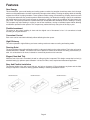
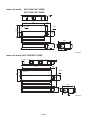
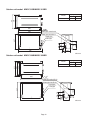
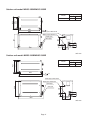
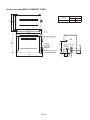
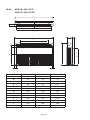
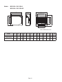
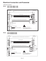
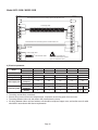
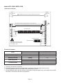
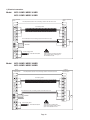
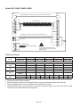
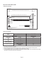
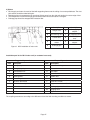
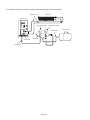
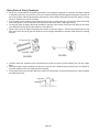
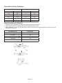
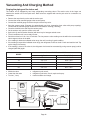
CMWSC -2006
Split Water Source Heat Pump
And Cooling Only Unit
Models: MWSC 010 B/BR MWSC 025 B/BR
MWSC 015 B/BR MWSC 030 B/BR
MWSC 020 B/BR MWSC 050 B/BR
Contents
Features ......................................................................................................................................2
Specifications .............................................................................................................................4
Outlines And Dimensions ..........................................................................................................7
Electrical Connection And Parameter ....................................................................................15
Installation Of Indoor Unit .......................................................................................................25
Installation Of Outdoor Unit ....................................................................................................36
Vacuuming And Charging Method ..........................................................................................42
Overall Checking ......................................................................................................................44
Remote Control Operation Guide ...........................................................................................45
Standard Operation Conditions ..............................................................................................47
Start-up ......................................................................................................................................47
Servicing And Maintenance .....................................................................................................48
Cleaning & Flushing System ...................................................................................................50
Troubleshooting .......................................................................................................................51
Note: Installation and maintenance are to be performed only by qualified personnel who are
familiar with local codes and regulations, and experienced with this type of equipment.
Caution: Sharp edges and coil surfaces are a potential injury hazard. Avoid contact with them.
Warning: Moving machinery and electrical power hazard. May cause severe personal injury or death.
Disconnect and lock off power before servicing equipment.
“McQuay” is a registered trademark of McQuay International. All rights reserved throughout the world.
© 2003 McQuay International
“Bulletin illustration cover the general appearance of McQuay International products at the time of publication and
we reserve the right to make change in design and construction at any time without notice”
Page 1
Features
Save Energy
This decentralized, year-round heating and cooling system consists of a two-pipe closed loop water circuit, through
which non-refrigerated water circulates continuously throughout the building. Locating the piping within the building
negates the need of for piping insulation. These systems achieve energy conservation by pumping heat from warm
to cold spaces whenever they coexist anywhere within the building. On demand for heating a space, the conditioner
will absorb heat from the loop circuit, whereas on demand for cooling a space, the conditioner will reject heat to the
loop circuit. The system provides the essential benefit of decentralized and individual choice of heating or cooling.
The occupant may select heating or cooling or shut off the conditioner, serving an individual space without affecting
conditioners operated in other spaces. The occupant may realize this freely at any time of the day or year.
Flexible Investment
The period of the project installing is short and the original cost of investment is low. It is convenient to install
according to occupant demand.
Convenient Control
Each room can be controlled individually without affecting the other space.
High Efficiency
The unit is operated in high efficiency and saves running cost due to water as cooling and heating media.
Running Quiet
The unit is designed into split configuration which is a thorough solution to the noise problem. The indoor unit can be
installed wherever is suitable. The outdoor unit can be placed on outside of the wall or the ceiling, at the balcony or
aisle. It is an ideal device for home, industrial or commercial place due to its low noise.
Elegant, Neat And Tidy
While the rest of the unit is concealed, the wall or ceiling air grilles is exposed. This design concept has in mind: (a)
aesthetic beauty (b) optimum space utilization. It is ideal for office, hotel, hospital and restaurants application.
Easy And Flexible Installation
The physical height of the unit is only 224 mm, and only a clearance of 75 mm between any beam and the false
ceiling is required. It is therefore offering greatest flexibility in selecting installation location.
ROOM LAYOUT 1
ROOM LAYOUT 2
ROOM LAYOUT 3
ADAPTOR
Page 2
Microcomputer remote control
The microcomputer remote control has following functions
• Five optional operation modes (heat/cool/dry/fan/auto).
• Fan speed can be set at high, medium, low and automatic.
• Sleep mode automatically increase set temperature since temperature is lower at night thus achieving healthy
sleep.
• Microcomputer controlled thermostat precisely controls room temperature resulting in energy saving and increases
comfort.
• Hot start and hot keep mode do not supply air for 30 sec. After deicing as well as initial operation of heating mode.
This prevents cold draft and maintains the indoor comfort.
• Timer on/off can be preset for the maximum of 15 hours.
Easy maintenance
This simple design concept has a friendly maintenance and servicing in mind. Access to all the internal parts of the
unit can be from either side panels or the top panel of the unit by loosening a few screws.
Page 3
Specifications
Ceiling Concealed Heat Pump Models
Indoor unit
MCC010M MCC010MR MCC015M MCC015MR MCC020M MCC020MR MCC025M MCC025MR MCC030M MCC030MR MCC050M MCC050MR
Outdoor unit
MWSC010B MWSC010BR MWSC015B MWSC015BR MWSC020B MWSC020BR MWSC025B MWSC025BR MWSC030B MWSC030BR MWSC050B MWSC050BR
Model
W
Rated heating capacity
W
Indoor Unit
Rated cooling capacity
Air flow
m³/h
Power source
V/Ph/Hz
2700
---
4200
3000
---
550
5600
4300
---
760
5600
---
1150
8200
7800
---
12300
10500
1400
---
15000
1700
2040
220V~/50Hz
380V/3N~/50Hz
External static
pressure
Pa
Dimension
length x wide x high
mm
830x566x224
930x566x224
Weight
kg
25
30
36
36
48
59
Sound level
dB(A)
38
38
42
49
43
46
0, 15, 30, 50
15, 30, 50, 70
1290x560x250
Compressor model
1290x560x250
1640x560x250
1900x560x250
ROTARY
SCROLL
TUBE IN TUBE
Type
Outdoor Unit
6900
BPHE
Water
flow
m³/h
0.56
0.8
1.1
1.3
1.6
2.5
Water
pressure
drop
kPa
7.8
11
16.6
14
12
20
Piping
size
in
Rc1/2
Rc3/4
G3/4
Dimension
length x wide x high
mm
736x411x437
802x421x548
839x498x545
Weight
kg
64
74
75
84
Sound level
dB(A)
2350
2350
3140
3460
Condenser
51
52
56
740
1170
725
---
34
Rated
power
Cooling
W
740
Heating
W
---
Rated
current
Cooling
A
Heating
A
62
63
63
1170
1635
1635
1800
1950
37
3.5
---
57
41
1100
5.5
3.4
---
5.2
41
41
85
42
---
1470
---
1840
---
2360
---
3500
7.5
7.6
8.3
9.0
11.1
10.8
5.7
7.0
---
6.8
---
8.6
---
10.8
---
7.3
0.85
1.05
2.4
2.4
2.95
3.15
R22
Refrigerant
Charge
Piping size
kg
0.6
0.65
0.8
0.85
1.0
1.15
Liquid pipe Φmm(in)
6.35(1/4")
6.35(1/4")
6.35(1/4")
9.52(3/8")
9.52(3/8")
9.52(3/8")
Φmm(in)
9.52(3/8")
12.7(1/2")
15.88(5/8")
15.88(5/8")
15.88(5/8")
19.05(3/4")
Gas pipe
Note: 1 specification will be subjected to change by manufacturer without prior notice.
2 cooling capacity is based on 26.7°C(DB),19.4°C(WB) entering air temperature and 29.4°C entering water
temperature,35°C leaving water temperature.
3 heating capacity is based on 21.1°C(DB),15.6°C(WB) entering air temperature and 21.1°C entering water
temperature.
Page 4
Ceiling Exposed Heat Pump Models
Indoor Unit
MCM020D
MCM020DR
MCM030D
MCM030DR
MCM050D
MCM050DR
Outdoor Unit
MWSC020B
MWSC020BR
MWSC030B
MWSC030BR
MWSC050B
MWSC050BR
Model
Cooling Capacity(W)
5250
5250
8200
8200
12300
12300
Heating Capactiy(W)
-
5600
-
10500
-
14500
Power Source
220V~/50Hz
380V/3N~/50Hz
Cooling
1495
1495
2350
2350
3060
3060
Heating
-
1480
-
2360
-
3500
Cooling
7.3
7.3
11.1
10.8
5.7
7.0
Heating
-
6.8
-
10.8
-
7.3
Indoor unit
48
48
50
50
52
Outdoor unit
41
41
41
41
42
42
Power Input( W)
Rated Current(A)
52
Sound Level dB(A)
Refrigerant
Charge (kg)
R22
1.0
1.0
2.8
2.98
3.4
3.4
Indoor Unit
39
39
44
44
64
64
Outdoor Unit
62
63
91
92
84
85
Weight (kg)
Liquid pipe
6.35
9.52
9.52
Gas pipe
15.88
15.88
19.05
Piping Size (mm)
Note: 1 specification will be subjected to change by manufacturer without prior notice.
2 cooling capacity is based on 26.7°C(DB),19.4°C(WB) entering air temperature and 29.4°C entering water
temperature,35°C leaving water temperature.
3 heating capacity is based on 21.1°C(DB),15.6°C(WB) entering air temperature and 21.1°C entering water
temperature.
Page 5
Ceiling Cassette Heat Pump Models
Indoor Unit
MCK 020A
Cooling Capacity
W
Heating Capacity
W
MCK 020AR
MCK 030A
5,600
—
MCK 030AR
MCK 050A
8,200
5,600
—
MCK 050AR
12,300
10,500
—
14,500
Liquid Pipe
Φmm(in)
6.35 (1/4")
9.52 (3/8")
9.52 (3/8")
Gas Pipe
Φmm(in)
15.88 (5/8")
15.88 (5/8")
19.05 (3/4")
Piping Size
Refrigerant
R22
Power Source
220V~/50Hz
Cooling
W
Heating
W
1,400
2,370
2,370
3,060
3,060
—
2,490
—
3,290
Power Input
Air Flow
m³/h
Weight(Indoor Unit)
kg
ESP
Pa
Sound Level
dB(A)
Outdoor Unit
—
1,480
1,100
37.5
1,300
37.5
39.5
1,850
39.5
39.5
39.5
0
41
MWSC 020B
45
MWSC 020BR
MWSC 030B
49
MWSC 030BR
MWSC 050B
MWSC 050BR
Liquid Pipe
Φmm(in)
6.35 (1/4")
9.52 (3/8")
9.52 (3/8")
Gas Pipe
Φmm(in)
15.88 (5/8")
15.88 (5/8")
19.05 (3/4")
Piping Size
Power Source
220V~/50Hz
380V/3N~/50Hz
Protection Device
Pressure Protector
Overload. Phase and Pressure
Protector
Rated
Current
Cooling
A
Heating
A
6.5
—
7.1
11.4
11.4
5.6
7.0
—
12.1
—
7.3
Water Flow
3
m /h
1.15
Water Pipe Size
in
Rc1/2
Weight(Outdoor Unit)
kg
62
63
91
92
84
85
Charge(R22)
kg
1.1
1.13
2.85
2.8
3.3
2.8
Sound Level
dB(A)
1.5
2.37
Rc3/4
41
41
42
Note: 1 specification will be subjected to change by manufacturer without prior notice.
2 cooling capacity is based on 26.7°C(DB),19.4°C(WB) entering air temperature and 29.4°C entering water
temperature,35°C leaving water temperature.
3 heating capacity is based on 21.1°C(DB),15.6°C(WB) entering air temperature and 21.1°C entering water
temperature.
Page 6
Outlines and Dimensions
Indoor unit model: MCC 010M /MCC 010MR
224
180
612
484
524
566
4-10x20
730
22
40
800
162
830
224
unit: mm
Indoor unit model: MCC 015M / MCC 015MR
224
180
712
484
524
566
4-10x20
830
22
40
900
162
930
224
unit: mm
Page 7
Indoor unit model:
MCC 020M / MCC 020MR
MCC 025M / MCC 025MR
965
258
262
270
R3/4
187
560
6-10x16
948
978
1290
208
118
250
560
280
13
unit: mm
Indoor unit model: MCC 030M /MCC 030MR
1315
258
262
270
R3/4
187
1298
1337
1640
208
118
560
250
560
6-10x16
280
13
unit: mm
Page 8
Outdoor unit model: MWSC 015B/MWSC 015BR
Piping size(mm)
Liquid
Gas
Model
φ6.35
φ12.7
411
381
329
MWSC025B/BR
637
698
4- 17
Water pipe outlet Rc1/2
Water pipe inlet Rc1/2
Liquid pipe
145
93 75
91
437
Gas pipe
170
83
736
unit: mm
Outdoor unit model: MWSC 020B/MWSC 020BR
Model
φ9.52
φ15.88
381
329
637
698
4- 17
Water pipe outlet Rc1/2
Water pipe inlet Rc1/2
Liquid pipe
Gas pipe
736
73
87 75
180
437
411
MWSC025B/BR
Piping size(mm)
Liquid
Gas
89
167
unit: mm
Page 10
Outdoor unit model: MWSC 025B/MWSC 025BR
Piping size(mm)
Liquid
Gas
Model
φ9.52
φ15.88
411
381
329
MWSC025B/BR
637
698
4- 17
Water pipe outlet Rc1/2
Water pipe inlet Rc1/2
84 64
92
437
Gas pipe
250
Liquid pipe
736
75 126
unit: mm
Outdoor unit model: MWSC 030B/MWSC 030BR
Piping size(mm)
Liquid
Gas
Model
421
391
339
MWSC030B/BR
696
759
φ9.52
φ15.88
4- 17
Water pipe outlet Rc3/4
Water pipe inlet Rc3/4
Liquid pipe
108
83 64
250
548
Gas pipe
73
802
165
unit: mm
Page 11
Outdoor unit model:MWSC 050B/MWSC 050BR
Piping size(mm)
Liquid
Gas
Model
498
468
408
MWSC050B/BR
723
783
φ9.52
φ19.05
4- φ17
Power line inlet port
77
Water pipe inlet G3/4
115
Liquid pipe
86
839
Page 12
64
Gas pipe
250
545
Water pipe outlet G3/4
156
Model :
MCM 020 / 030 / 050 D
MCM 020 / 030 / 050 DR
B
B
A
A
C
C
G
G
F
F
E
E
I
I
J
J
D
D
L
L
PULL
PULL
PULL
PULL
PULL
K
K
PULL
M
M
PULL
PULL
H
H
MODEL
MCM 020D/DR
MCM 030D/DR
MCM 050D/DR
A
1174
1174
1674
B
75
75
75
C
1082
1082
1582
D
68
68
68
E
58
93
93
F
156
156
156
G
1214
1214
1714
H
57
57
57
I
670
670
670
J
216
216
216
K
319
319
319
L
879
879
1379
M
517
517
517
Page 13
MCK 020 / 030 / 050 A
MCK 020 / 030 / 050 AR
E
H
G
J
L
I
F
C
A
B
D
K
Model :
M
Note : Dimension in mm
Model
A
B
C
D
E
F
G
H
I
J
K
L
M
MCK020A/AR
820
875
548
820
363
335
28
930
930
642
622
555
555
MCK030A/AR
820
875
548
820
363
335
28
930
930
642
622
555
555
MCK050A/AR
820
875
548
820
363
335
28
930
930
642
622
555
555
Page 14
Electrical Connection and Parameter
1) Electrical connection
Model:
MCC 010M / MWSC 010B
MCC 015M / MWSC 015B
Indoor
terminal block
The temperature sensor wire connecting outdoor unit with indoor
unit
Outdoor
terminal block
N
COMP
L
The malfunction wire connecting outdoor unit with indoor unit
F
E1
E3
WV COMP
N
Connecting cable
220-240V
Power supply cable
There must be a double pole
switch with minimum 3mm contact
gap in the installation circuit.
220-240V/1Ph/50Hz
L
N
E
N
L
MCC020M/MWSC020B
MCC025M/MWSC025B
Indoor
terminal block
The temperature sensor wire connecting outdoor unit with indoor unit
Outdoor
terminal block
N
COMP
L
The malfunction wire connecting outdoor unit with indoor unit
E2
E3
WV COMP
N
Connecting cable
E1
220-240V
N
Power supply cable
E
N
L
220-240V/1Ph/50Hz
There must be a double pole
switch with minimum 3mm contact
gap in the installation circuit.
L
Model:
Page 15
F
Model: MCC 030M / MWSC 030B
Indoor
terminal block
Outdoor
terminal block
The temperature sensor wire connecting outdoor unit with indoor unit
L
COMP
L
WV COMP
N
L
N
N
Connecting cable
E3
The malfunction wire connecting outdoor unit with indoor unit
E2
F
E1
220-240V
Power supply cable
220-240V/1Ph /50Hz
There must be a double pole
switch with minimum 3mm contact
gap in the installation circuit.
L
N
E
N
L
2) Electrical parameter
Model
Indoor unit
MCC 010M
MCC 015M
MCC 020M
MCC025M
MCC 030M
Outdoor unit
MWSC 010B
MWSC 015B
MWSC 020B
MWSC025B
MWSC 030B
Power source
220V~/50Hz
Power input(W)
Cooling
740
1,700
1,635
1,800
2,350
Running current(A)
Cooling
Section
area(mm²)
Quantity
Section
area(mm²)
Quantity
3.5
5.5
7.5
8.3
11.1
2.5
2.5
2.5
2.5
2.5
3
3
3
3
3
2.5
2.5
2.5
2.5
2.5
1.5
3
3
3
3
2
2
Power supply wire
Connecting cable
ó
ó
ó
ó
The wiring must be firmly connected.
Electric wiring must not touch the refrigerant pipe, compressor and moving parts of the fan motor.
The wiring between indoor unit and outdoor unit must be fixed by clamp.
All wiring between indoor unit and outdoor unit should be neoprene copper core, and section area of cable
should be in accordance with above requirements.
Page 16
Model: MCC 050M / MWSC 050B
1) Electrical connection
The temperature sensor wire connecting outdoor unit with indoor
unit
F
E2
E1
The malfunction wire connecting outdoor unit with indoor unit
Outdoor
terminal block
A
Indoor
terminal block
LIVE E3
220-240V
N
COMP WV
WV COMP
N
L
L
N
Connecting cable
T
Power supply cable
S
380-415V/3Ph-50Hz
R
There must be a three pole switch
with minimum 3mm contact gap in
the installation circuit.
2) Electrical parameter
Indoor unit
Outdoor unit
Model
Power source
Power input(W)
Running current(A)
Power supply wire
Connecting cable
ó
ó
ó
ó
Cooling
Cooling
Section area(mm²)
Quantity
Section area (mm²)
Quantity
MCC 050M
MWSC 050B
380V/3N~/50Hz
3,140
5.7
2.5
5
1.5
5
The wiring must be firmly connected.
Electric wiring must not touch the refrigerant pipe, compressor and moving parts of the fan motor.
The wiring between indoor unit and outdoor unit must be fixed by clamp.
All wiring between indoor unit and outdoor unit should be neoprene copper core, and section area of cable
should be in accordance with above requirements.
Page 17
1) Electrical connection
Model:
MCC 010MR / MWSC 010BR
MCC 015MR / MWSC 015BR
Indoor terminal
block
The temperature sensor wire connecting outdoor unit with indoor unit
Outdoor terminal
block
L
The malfunction wire connecting outdoor unit with indoor unit
E3
WV
4WV COMP
4WV COMP
N
N
Connecting cable
E1
220-240V
F
Power supply cable
There must be a double pole switch
with minimum 3mm contact gap in
the installation circuit.
220-240V/1Ph/50Hz
L
N
E
N
L
MCC 020MR / MWSC 020BR
MCC 025MR / MWSC 025BR
Indoor
terminal block
The temperature sensor wire connecting outdoor unit with indoor unit
Outdoor
terminal block
4WV COMP N
L
The malfunction wire connecting outdoor unit with indoor unit
E3
WV
4WV COMP
N
Connecting cable
E1
E2
220-240V
N
Power suplly cable
E
N
L
220-240V/1Ph/50Hz
There must be a double pole
switch with minimum 3mm contact
gap in the installation circuit.
L
Model:
Page 18
F
Model: MCC 030MR / MWSC 030BR
Outdoor terminal
block
Indoor terminal
block
The temperature sensor wire connecting outdoor unit with indoor unit
4WV COMP
L
WV 4WV COMP
N
L
N
N
Connecting cable
E3
L
The malfunction wire connecting outdoor unit with indoor unit
220-240V
E1
E2
F
Power supply cable
N
E
N
L
220-240V/1Ph/50Hz
L
There must be a double pole switch
with minimum 3mm contact gap in the
installation circuit.
2) Electrical parameter
Model
Indoor unit
MCC 010MR
MCC 015MR
MCC 020MR
MCC025MR
MCC 030MR
Outdoor unit
MWSC 010BR
MWSC 015BR
MWSC 020BR
MWSC025BR
MWSC 030BR
Power source
220V~/50Hz
Power input
(W)
Cooling
740
1,170
1,635
1,950
2,350
Heating
725
1,100
1,470
1,840
2,360
Running current
(A)
Cooling
3.5
5.5
7.6
9.0
10.8
Heating
3.4
5.2
6.8
8.6
10.8
Power supply
wire
Section area(mm²)
2.5
2.5
2.5
2.5
2.5
Connecting
cable
Section area (mm²)
2.5
1.5
2.5
1.5
2.5
1.5
2.5
1.5
2.5
1.5
Quantity
2
2
2
2
2
2
2
2
2
3
ó
ó
ó
ó
Quantity
3
3
3
3
3
The wiring must be firmly connected.
Electric wiring must not touch the refrigerant pipe, compressor and moving parts of the fan motor.
The wiring between indoor unit and outdoor unit must be fixed by clamp.
All wiring between indoor unit and outdoor unit should be neoprene copper core, and section area of cable
should be in accordance with above requirements.
Page 19
Model: MCC 050MR / MWSC 050BR
1) Electrical connection
Indoor terminal
block
Outdoor terminal
block
F
E2
E1
The malfunction wire connecting outdoor unit with indoor unit
A
The temperature sensor wire connecting outdoor unit with indoor unit
L LIVE E3
220-240V
N 4WV COMP WV
N
WV 4WV COMP L
N
Connecting cable
T
Power supply cable
R
S
380-415V/3Ph/50Hz
There must be a three pole switch with
minimum 3mm contact gap in the
installation circuit.
2) Electrical parameter
Indoor unit
Outdoor unit
Model
Power source
Power input
(W)
Running current
(A)
Power supply wire
Connecting cable
ó
ó
ó
ó
Cooling
Heating
Cooling
Heating
Section area(mm²)
Quantity
Section area (mm²)
Quantity
MCC 050MR
MWSC 050BR
380V/3N~/50Hz
3,460
3,500
7.0
7.3
2.5
5
1.5
6
The wiring must be firmly connected.
Electric wiring must not touch the refrigerant pipe, compressor and moving parts of the fan motor.
The wiring between indoor unit and outdoor unit must be fixed by clamp.
All wiring between indoor unit and outdoor unit should be neoprene copper core, and section area of cable
should be in accordance with above requirements.
Page 20
Model :
MCK 020A/ MWSC 020B MCK 030A/ MWSC 030B
MCM 020D/ MWSC 020B MCM 030D / MWSC 030B
1) Electrical connection
Indoor unit
Outdoor unit
Terminal block
Terminal block
Connecting cable
N
N
COMP
COMP
A
A
W
F
F
N
L
E
N
L
Power supply wire
220-240/1Ph/50Hz
There must be a double pole
switch with minimum 3 mm contact
gap in the fixed installation circuit.
2) Electrical parameter
Model
Indoor unit
MCK 020A
MCK 030A
MCM 020D
MCM 030D
Outdoor unit
MWSC 020B
MWSC 030B
MWSC 020B
MWSC 030B
Power source (V/Ph/Hz)
220-240 / 1 / 50
Power input (W)
Cooling
1560
2480
1530
2250
Running current (A)
Cooling
7.1
12
7.1
10.5
Section area(mm2)
3.3
3.3
4
4
Quantity
3
3
3
3
Section area(mm2)
3.3
3.3
4
4
Quantity
4
4
4
4
Power supply wire
Connecting cable
Page 21
Model :
MCK 050A / MWSC 050B
MCM 050D / MWSC 050B
1) Electrical connection
Indoor unit
Outdoor unit
Terminal block
Terminal block
Connecting cable
N
N
L
L
COMP
COMP
A
A
F
F
N
Power supply wire
380-415V/3Ph/50Hz
N
T
S
R
E
T
S
R
There must be a three pole
switch with minimum 3 mm
contact gap in the fixed
installation circuit.
2) Electrical parameter
Indoor unit
Outdoor unit
Power source (V/Ph/Hz)
Power input(W)
Cooling
Running current(A)
Heating
Section area(mm²)
Power supply wire
Quantity
Section area (mm²)
Connecting cable
Quantity
Model
Page 22
MCK 050A
MCM 050D
MWSC 050B
MWSC 050B
380-415 / 3 / 50
3130
3280
5.9
5.8
3.3
4
5
5
1.5
4
5
5
Model :
MCK 020AR / MWSC 020BR
MCM 020DR / MWSC 020BR
MCK 030AR / MWSC 030BR
MCM 030DR / MWSC 030BR
1) Electrical connection
Indoor unit
Outdoor unit
Terminal block
Terminal block
Connecting cable
N
N
COMP
COMP
4WV
4WV
A
A
W
F
F
N
L
E
N
L
There must be a double pole
switch with minimum 3 mm
contact gap in the fixed
installation circuit.
Power supply wire
220-240V/1Ph/50Hz
2) Electrical parameter
Indoor unit
MCK 020AR
MCK 030AR
MCM 020DR
MCM 030DR
Outdoor unit
MWSC 020BR
MWSC 030BR
MWSC 020BR
MWSC 030BR
Power input
(W)
Cooling
1560
2420
1530
2250
Heating
1580
2445
1560
2460
Running current
(A)
Cooling
7.1
11.8
7.0
10.2
Model
Power source (V/Ph/Hz)
Power supply wire
Connecting cable
220-240 / 1 / 50
Heating
7.2
11.9
7.2
11
Section area(mm²)
2.0
3.3
4
4
Quantity
3
3
3
3
Section area (mm²)
3.3
3.3
4
4
Quantity
5
5
5
5
Page 23
Model :
MCK 050AR / MWSC 050BR
MCM 050DR / MWSC 050BR
Indoor unit
Outdoor unit
Terminal block
Terminal block
Connecting cable
N
N
L
L
COMP
COMP
4WV
4WV
A
A
F
F
N
Power supply wire
380-415V/3Ph/50Hz
There must be a three pole
switch with minimum 3 mm
contact gap in the fixed
installation circuit.
N
T
S
R
E
T
S
R
2) Electrical parameter
Indoor unit
Outdoor unit
Power source (V/Ph/Hz)
Cooling
Power input(W)
Heating
Cooling
Running current(A)
Heating
Section area(mm²)
Power supply wire
Quantity
Section area (mm²)
Connecting cable
Quantity
Model
Page 24
MCK 050AR
MCM 050DR
MWSC 050BR
MWSC 050BR
380-415 / 3 / 50
3460
3280
3580
3560
6.3
5.8
6.4
6.4
3.3
4
5
5
1.5
4
6
6
Installation Of Indoor Unit
Installation of MCC unit
1) Preliminary site survey
Electrical supply and installation is to conform to local authorityʼs codes and regulations (e.g. National Electricity
Board), Voltage supply fluctuation must not exceed ± 10% voltage. Voltage supply lines must be independent of
welding transformers which can cause high voltage fluctuation. Ensure that the location is convenient for wiring
and piping.
2) Installation of indoor units
The indoor unit must be installed such that there is no short circuit of the cool discharge, comply to the installation
clearance recommended and make sure the location is suitable for piping and drainage.
The precaution steps:
I. Use the hanger supplied with the unit.
II. Ensure the support is stronger enough to withstand the weight of the unit.
III. Use the supplied drain socket to connect drainage pipe.
IV. The unit must be installed in such a way that the condensed water can be flowed out smoothly.
Installation of ducts for MCC indoor unit
1) Air-supplying ducts
Two kinds of ducts are available, rectangular and round ducts (200mm).
Rectangular ducts are connected directly to discharge collar of indoor unit (Figure1).
Adding air-supplying adaptor to connect between indoor unit and round duct which elongating to the
air-distribution box and length of round duct should not be more than 6 meters (Figure 2).
Rivet hole
1
2
3
4
H
5
6
L
Figure 2 Connection for round duct.
Figure 1 Connection for rectangular duct.
Ducting sizes (mm)
Dim
Model
MCC 010
M/MR
MCC 015
M/MR
MCC 020
M/MR
MCC 025
M/MR
MCC 030
M/MR
MCC 050
M/MR
L
747
847
960
960
1310
1570
H
170
170
120
120
120
120
200
200
200
200
200
200
Size
Rectangular
Round ∅
Page 25
Item
Description of Figure 2
1
Indoor unit
2
Flexible connector or plenum box
3
Air-supplying adaptor
4
Round duct
5
Air-distribution adaptor
6
Air-distribution box
Model
Recommended
No.
MCC010
M/MR
MCC015
M/MR
MCC020
M/MR
MCC025
M/MR
MCC030
M/MR
MCC050
M/MR
1
1~2
2~3
3~4
3~4
3~5
Length (m)
6
2
Area cooling space (m )
15~25
8
25~35
40~60
45-70
50~75
85~130
2) Air-returning duct (see Figure 3)
One end of air-returning duct can be jointed by a foldable canvas duct reinforced by 8” steel wire to make it easy
to match different ceiling height.
Item
Description
Item
Description
1
Air-returning shutter
4
Indoor unit
2
Canvas duct
5
Wood screw
3
Air-returning duct
6
Rivet
Figure 3. Connection for air-returning
duct
3) Insulation (Figure 4)
It is necessary to put heat-insulated layer on the air-supplying duct and air-returning duct. Firstly, stick the glue
anchor on the ducts. Then, cover the ducts with al-foil insulation fiber which should be fixed with glue anchor cover
finally using the adhesive taper to seal the gap-line
Item
Description
Item
Description
1
GI plate
4
foil
2
Glue anchor
5
Glue anchor cover
3
Heat-insulation
insulation layer
6
Glue taper
Figure 4. Insulation
Page 26
4) Others
ó Each supply and return air must be fixed with supporting frame onto the ceiling of concrete prefabricate. The duct
joint section should be sealed with glue.
ó Returning air-box is suggested to be more than 150mm away from the side wall starting from outer edge of box.
ó The obliqueness of level of drainage pipe should be taken into account about 1% degree.
ó Drainage pipe should be wrapped with insulation fiber.
Item
description
Item
description
1
Hanger hook
6
Air-supplying
adaptor
2
Air-returning duct
7
Air-supplying duct
3
Canvas duct
8
Distributing air
duct
4
Air-returning
shutter
9
Air-distribution
adaptor
5
Drainage pipe
Figure 5. MCC installation of indoor unit
Installation part list for MCC indoor unit (on customerʼs account)
Suggested by manufacturer
Item
Description
Prepared by customer
Item
Description
1
Air-supplying duct
1
Heat-insulation layer
2
Air-supplying adaptor
2
Glue anchor
3
Air-distribution box
3
Glue taper
4
Screw M6x30
4
Glue
5
Sealed gasket
5
Draw-in bolt
6
Air-returning duct
6
Copper tube heat-insulation
7
Electronic thermostat
7
Cable wire vv3*25
8
Air-distribution adaptor
8
Copper core wire bvv-1.5mm2
9
filter
9
Drainage pipe heat-insulation
10
Hanging hook
11
Tighten belt
The requiring amounts are according to the different unit and the field mounting conditions to ensure.
Page 27
Installation of MCK unit
Preliminary site survey
ó Electrical supply and installation is to conform to local authorityʼs (e.g. National Electrical Board) codes and
regulations.
ó Voltage supply fluctuation must not exceed ±10% of rated voltage. Electricity supply lines must be independent of
welding transformers, which can cause high supply fluctuation.
ó Ensure that the location is convenient for wiring, piping and drainage.
ó The indoor unit must be installed in such that free from any obstacles in path of cool air discharge and warm air
return, and must allow spreading of air throughout the room (near the center of the room).
ó Must be provided clearance for the indoor unit from the wall and obstacles as show in the figure.
ó The installation place must be strong enough to support a load 4 times the indoor unit weight to avoid amplifying
noise and vibration.
ó The installation place (handing ceiling surface) must be assured the levelness and height in the ceiling is 350 mm
or more.
ó The indoor unit must be away from heat and steam sources (avoid installing it near an entrance).
Page 28
Unit Installation
ó Measure and mark the position for the hanging rod. Drill the hole for the angle nut on the ceiling and fix the
handing rod.
ó The installation template is extended according to temperature and humidity. Check on dimensions in used.
ó The dimensions of the installation template are as same as those in the ceiling opening dimensions.
ó When ceiling lamination work is not completed, be sure to fit the installation template to the indoor unit.
NOTE:
Be Sure to discuss the ceiling drilling work with the installers
concerned.
Dimension in mm
Unit Hanging
ó Confirm the pitch of the hanging rod is 620.4mm×790.0mm sharp.
ó Attach the hanger bracket with the nut and washer to the hanging rod. Hold the unit and hang it on the hanger
bracket.
ó Adjust the unit height to 35.0 mm between the indoor unit bottom surface and the ceiling surface.
ó Confirm with a level gauge that the unit is installed horizontally and tighten the nut and bolt to prevent unit falling
and vibration.
ó Open the ceiling board along the outer edge of the paper installation template.
Hanging Rod
Nut
Indoor unit
Spring Washer
Flat Washer
Ceiling Board
35mm
Flat Washer
Nut
Page 29
Drain Piping Work
ó
ó
ó
ó
ó
Drainpipe must be in downward gradient for smooth drainage.
Avoid the drainpipe in up and down slope to prevent reversed water flow.
During the drain piping connection, be careful not to exert extra force on the drain connector at indoor unit.
The outside diameter of the drain connection at the flexible drain hose is 20mm.
Be sure to execute heat insulation (polyethylene foam with thickness more than 8.0mm) on the drain piping to
avoid the condensed water dripping inside the room.
Feed Water
Indoor
Unit
Main Drain Pipe
Pipe Clamp
Flexible Drain Hose
GOOD
BAD
Drain Test
ó Connect the main drainpipe to the flexible drain hose.
ó Feed water from flexible drain hose and check the piping for leakage.
ó When the test is completed, connect the flexible drain hose to the drain connector on the indoor unit.
NOTE:
This indoor unit uses drain pump for condensed water drainage. Install the unit horizontally to prevent water
leakage or condensation around the air outlet.
Panel Installation
ó The front panel can only be fitted in one direction, follow the piping direction. (Follow piping arrow sticker on front
panel)
ó Be sure to remove the installation template before installing the front panel.
ó Open the air intake grille by pull back the catchers and remove it together with filter from panel.
ó Install the front frame panel onto the indoor unit by 4 screw and tighten it completely to prevent cool air leakage.
ó Connect the LED wire and air swing wire to the indoor unit.
Page 30
Note :
Install the front frame panel firmly to prevent
cool air leakage which will cause
condensation and water dripping
Indoor Unit
Cool
Air
Cool
Air
Air leak
Air leak
Ceiling Board
Ceiling Board
Panel
Good Installation
Bad Installation
Air intake grille installation
ó
ó
ó
ó
ó
Before installed the air intake grille, be sure to fix the ionizer filter to the air filter.
Fix the ionizer filter to the air filter with the black side on top and white side at bottom.
Carefully clip on the ionizer filter frame.
Install the air intake grille together with the air filter to the front panel.
The grille can be fit in any direction, when selecting direction, the ceiling design and grille operability should be
considered.
FRAME
IONEIZER
FILTER
Page 31
Installation of MCM unit
Preliminary site survey
ó Electrical supply and installation shall conform to the local authority (e.g. National Electrical Board).
ó Voltage supply fluctuation must not exceed ± 10% of the rated voltage. Electricity supply lines must be independent
of welding transformers which can cause high supply fluctuation.
ó Ensure that the installation location is convenient for wiring and piping.
Standard Mounting
Ensure that the overhead supports are strong enough to hold the weight of the unit. Position the hanger rods (wall
mounting bracket for floor standing) and check for its alignment with the unit as shown in Figure A. Also, check that
the hangers are secured and the base of fan coil unit is leveled in both horizontal directions, taking into account the
gradient for drainage flow as recommended in Figure A.
Note: Dimension in mm
MODEL
MCM020D MCM030D MCM050D
A
1214
1214
1714
B
666
666
666
C
273
273
273
D
130
130
130
E
1160
1160
1560
F
27
27
27
G
77
77
77
H
745
745
1235
I
25
25
25
J
209
209
331
K
486
486
486
L
108
108
108
M
360
360
600
N
770
770
1270
O
136
136
136
P
373
373
373
Q
222
222
310
FIGURE A
A
H
I
M
B
C
K
D
L
G
F
E
P
P
O
Q
Page 32
J
N
Please ensure that following steps are taken:
ó Check the gradient for drainage flow as recommended in Figure B.
ó Provide clearance for easy servicing and optimal air flow as shown in Figure C.
10mm HIGHER
10mm
FIGURE B
PULL
PULL
PULL
PULL
ó The indoor unit must be installed such that there is no short circuit of the cool discharge air with the warm return
air.
FIGURE C
Min 500mm
Min 10mm
Min 300mm
Max 250mm
UTENSILS, FURNITURES OR BUILT-IN
ARCHITECTUAL FEATURES MUST NOT
PROTURDE MORE THAN 250.0MM.
CEILING EXPLORED TYPE
ó Do not install the indoor unit where there is direct sunlight shining on the unit. The location should be suitable for
piping and drainage installation. The unit must be a large distance away from the door.
Min 400mm
Min 1.0m
PULL
PULL
PULL
PULL
FLOOR STANDING TYPE
Page 33
SEMI-ENCLOSE SCISSOR
ó In case the unit is to be half-recessed into a false ceiling, please check that the unit is wellaligned.
ó Provide the installation space as shown in figure D.
FIGURE D
300
.0
62
1.0
10
.0
300
.0
10
.0
10. 0mm
10 mm
TOP PANEL OF UNIT
166mm
CEILING BOARD
10mm
STEP 1:
Remove the air intake grille, side panel, side close-up and hanger bracket from the unit. See Figure E.
FIGURE E
SIDE CLOSE UP
HANGER BRACKET
SIDE FRAME
AIR INTAKE GRILLE
Page 34
STEP 2:
Position the hanger rods as shown in Figure B, and install the hanger bracket.
See Figure F.
FIGURE F
STEP 3:
Hang up the unit and tighten the bolt. After completing the piping and draining pipe, install back the grille and panel.
See Figure G.
FIGURE G
INSTALLATION-FLOOR STANDING TYPE
STEP 1:
Remove the air intake grille, side close-up and side panel from the unit. See Figure E.
STEP 2:
There are two types of piping and draining pipe connection, as shown in Figure H.
FIGURE H PIPING AND DRAIN PIPE INATALLATION
WALL
WALL
PIPING & DRAIN
PIPE FROM TOP
PANEL
OR
Page 35
PIPING & DDRAIN PIPE
FROM BACK PANEL
Installation Of Outdoor Unit
The location of the outdoor unit is very flexible, it can be installed in ceiling, stairs, toilet and out wall or other places.
In order to operate the unit reliable, precaution steps:
1) Leave enough space for service person to perform maintenance of repair and provide sufficient room to make
water, electrical connections.
2) The place can withstand the weight of the outdoor unit and isolate the noise and vibration.
400mm
Water flow switch
500mm
Barrier
Barrier
Water filter
Bolt
Shockproofinsulator
3) If unit is suspended from the ceiling by four threaded rods. The rods are attached to the unit supportably by a
hanger bracket through a rubber isolator.
3/8" THREADED ROD
VIBRATION ISOLATOR
WASHER 3/8"
HEX NUTS
Caution : Do not use rods smaller than specified above. The rods must be securely anchored to the ceiling
or to the bar joist.
Page 36
Refrigerant Piping Work
Refrigerant piping is important in particular. Refrigeration cycle of the split air conditioner is realized by the perfect
piping work.
Piping length and elevation
If the piping is too long, both the capacity and reliability of unit will drop. As the number of bends increase, resistance
to flow of refrigerant system increases, thus lowering cooling capacity and as a result the compressor may become
defective. Always choose the shortest path and follow the recommendation as tabulated.
Model
MWSC
010B/BR
MWSC
015B/BR
MWSC
020B/BR
MWSC
025B/BR
MWSC
030B/BR
MWSC
050B/BR
Max. Length, L
7m
10m
15m
15m
20m
20m
Max. Elevation H
5m
8m
8m
8m
10m
10m
Max. No. Of bends
10
10
10
10
10
10
Liquid pipe size
1/4”
1/4”
1/4”
3/8”
3/8”
3/8”
Gas pipe size
3/8”
1/2”
5/8”
5/8”
5/8”
3/4”
Number
t For cooling unit, need to add external accumulator (recommended 6kg accumulator).
A. Outdoor lower than indoor unit
B. Outdoor unit higher than indoor unit
Liquid check trapper
Indoor unit
Max. height
Max. height
Outdoor unit
Oil trapper
(Set one per six meter)
:
Note
Outdoor unit
Liquid pipe
Gas pipe
Indoor unit
Installation of pipe
All system piping should be installed in accordance with local ordinances. The piping should be designed with a
minimum number of bends and changes in elevation to keep costs to a minimum and unit performance to a maximum.
A good installation should include the followings:
ó
ó
ó
ó
ó
ó
Vibration eliminators to reduce vibration and noise transmission to the building.
Shut-off valves are required to isolate the unit from the piping system during service.
Manual or automatic air vent valve at the high points of the system.
Some means to maintaining adequate system pressure (e.g. regulating valve and /or expansion tank )
Install temperature and pressure indicators at the unit pipe to aid in servicing and troubleshooting
Install a strainer to remove foreign matter from the water before it enters the pumps, it should be located far
enough from the upstream of pump to prevent cavitation at the inlet.
Page 37
Piping Connection
1) Do not use contaminated or damaged copper tubing. If any piping, evaporator or condenser had been exposed
or had been opened for 15 seconds or more, then vacuum and purge with field supplied refrigerant. Generally, do
not remove plastic, rubber plugs and brass nuts from the valves, fittings tubing and coils until it is ready to connect
suction or liquid line into valves or fittings.
2) If any brazing work is required, ensure that nitrogen gas is passed through coil and joints while the brazing work
is being done. This will eliminate soot formation on the inside wall of copper tubing.
3) Cut the pipe stages by stages, advancing the blade of pipe cutter slowly. Extra force and a deep cut will cause
more distortion of pipe and therefore extra burr.
4) Remove burrs from cut edges of pipes with a remover. This will avoid unevenness on the flare face which will
cause gas leak.
5) Align the center of the piping and sufficiently tighten the flare nut with fingers. Finally, tighten the flare nut with
torque wrench until the wrench clicks.
6) Be sure to execute heat insulation (polyurethane form with thickness more than 15 mm).
7) Except the outdoor unit which is pre-charged with refrigerant R22, the indoor unit and the refrigerant connection
pipes must be purged because the air that contain moisture remaining in the refrigerant cycle may cause
malfunction to the compressor.
Vacuuming and charging
The precharged outdoor unit does not need any vacuuming or charging, However once it is connected, the connecting
pipe line and the indoor unit need to be vacuumed before releasing the R22 from the outdoor unit.
1) Open the service port core cap.
2) Connect pressure gauge to the service port.
3) Connect the line to vacuum pump, open the charging manifold valve and turn the pump on, vacuum to -0.1MPa(76cmHg) or lower (Evacuation time varies by the pump but averagely in 1 hour).
4) After evacuation, unscrew the spindle for the gas to run to indoor unit.
Refrigerant pipe
Indoor unit
Outdoor unit
Low pressure guage
High pressure guage
Flexible pipe
Charge cylinde
R22
Check valve
Charge set
Scare pan
Flexible pipe
Page 38
5) If systemʼs refrigerant is leaked, recharge refrigerant referring to following diagram.
Refrigerant pipe
Indoor unit
Outdoor unit
Low pressure guage
High pressure guage
Flexible pipe
Charge set
Check valve
Flexible pipe
Page 39
Vacuum pump
Piping Works & Flaring Technique
ó Do not use contaminated or damaged copper tubing. If any pipings, evaporator or condenser had been exposed
or had been opened for 15 seconds or more, then vacuum and purge with field supplied refrigerant. Generally, do
not remove plastic, rubber plugs and brass nuts from the valves, fittings, tubing and coils until it is ready to connect
suction or liquid line into valves or fittings.
ó If any brazing work is required, ensure that the nitrogen gas is passed through coil and joints while the brazing
work is being done. This will eliminate soot formation on the inside walls of the copper tubing.
ó Cut the pipe stage by stage, advancing the blade of the pipe cutter slowly. Extra force and deep cut will cause
more distortion on the pipe and thus extra burr. See Figure K.
ó Remove burrs from cut edges of the pipes with remover as shown in figure L. This will avoid unevenness on the
flare faces which will cause gas leak. Hold the end of the pipe downwards to prevent metal chips from entering
the pipe.
COPPER TUBE
FIGUREL
FIGUREK
ó Insert the flare nuts, mounted on the connection parts of both the indoor unit and outdoor unit, onto the copper
pipes.
ó The exact length of pipe protruding from the face of the flare die is determined by the flaring tool. See Figure M.
The table shows the use of an imperial die and rigid die.
ó Fix the pipe firmly on the flare die. Match the centers of both the flare die and the flaring punch, and then tighten
the flaring punch fully.
Page 40
Piping Work & Flaring Technique
TUBE D
A (mm)
Inch
mm
Imperial
Rigid
1/4”
6.35
1.3
0.7
3/8”
9.52
1.6
1.0
1/2”
12.70
1.9
1.3
5/8”
15.88
2.2
1.7
3/4”
19.05
2.5
2.0
Piping Connection To The Units
ó Align the center of the piping and tighten the flare nut sufficiently with fingers.
ó Finally, tighten the flare nut with the torque wrench until the wrench clicks.
ó When tightening the flare nut with the torque wrench, ensure that the tightening direction follows the arrow
indicated on the wrench.
PIPE SIZE mm (in)
Torque (mm)
6.35 (1/4)
18
9.52 (3/8)
42
12.7 (1/2)
55
15.88 (5/8)
65
19.05 (3/4)
78
Page 41
Vacuuming And Charging Method
Purging the piping and the indoor unit
The outdoor unit is equipped by two 3-way refrigerating connecting valves. The suction valve is the larger one
whereas the smaller one is the liquid valve. Both valves are supplied with service port valve for connection to a
manometer.
ó
ó
ó
ó
ó
ó
ó
ó
ó
ó
ó
ó
Remove the caps from the valve and the service port.
Connect the center manifold gauge to the vacuum pump.
Connect the manifold gauge to the service port of the 3-way valve.
Start the vacuum pump. Evacuate for approximately one hour (evacuation time varies with pump capacity).
Confirm that the manifold gauge needle has moved towards –30inHg (-76cmHg).
Close the manifold valve and stop the vacuum pump.
On the outdoor unit, open the suction valve and
liquid valve (in anti-clockwise direction) with 4mm key for hexagon sacked screw.
The air conditioner unit is now ready for start.
Start the unit and run it for 10 to 15 minutes. The low pressure valve reading must be within the recommended
value range as shown in the table.
If the reading is within the indicated value range, the unit is running in good condition.
If the reading is beyond the indicated value range, the refrigerant circuit has a leak. Check and seal the leak. Top
up the charge if necessary.
If the reading is close to the value 0, the refrigerant circuit must be evacuated (by using vacuum pump) and be
charged (with R22) again.
Indoor 27 °C /Outdoor 35 °C
MODEL
kgf/cm2
Psi (=lbf/in2)
10
4.5 ~ 5.4
64.0 ~ 76.8
15
4.5 ~ 5.4
64.0 ~ 76.8
20
4.5 ~ 5.6
64.0 ~ 79.6
30
4.9 ~ 5.3
69.7 ~ 75.4
50
4.9 ~ 5.6
69.7 ~ 79.6
ó Within the value
ó Lower than the value
ó Too low ( ̃ zero)
OUTDOOR UNIT
ó
ó
ó
refrigerant cycle normal.
refrigerant cycle leaks. Check, repair and top-up.
need evacuation and charge
REFRIGERANT PIPING
GAS VALVE
LOW SIDE
PRESSURE GAUGE
INDOOR UNIT
HIGH SIDE
PRESSURE GAUGE
VACUUM PUMP
FLEXIBLE HOSE
LIQUID VALVE
MANIFOLD
Page 42
Additional Charge
The refrigerant is pre-charged in the outdoor unit. If the piping length is less than 5m, then additional charge after
vacuuming is not necessary. If the piping length is more than 5m, then use the additional charge valve as in the table
below.
MODEL
R22 CHARGE (±5g/m)
MWSC 010 B/BR
22
MWSC 015 B/BR
22
MWSC 020 B/BR
22
MWSC 025 B/BR
25
MWSC 030 B/BR
50
MWSC 050 B/BR
60
Additional charge operation
The operation must be done by using gas cylinder and precise weighting machine obligatorily. The additional charge
is top-up into the outdoor unit using the suction valve via the service port.
ó Remove the service valve plug.
ó Connect the low pressure manifold to the suction service port, center manifold to the cylinder tank and close the
high pressure manifold (see figure below). Purge all the flexible hose with refrigerant gas.
ó Start the air conditioner unit.
ó Open the gas cylinder and low pressure manifold valve.
ó When the required refrigerant quantity is pumped into the unit, close the low pressure manifold and the gas
cylinder valve.
ó Disconnect the manometer and the gas cylinder. Put back the service port cap.
OUTDOOR UNIT
REFRIGERANT PIPING
INDOOR UNIT
GAS VALVE
LOW SIDE
PRESSURE GAUGE
HIGH SIDE
PRESSURE GAUGE
REFRIGERANT
GAS TANK
FLEXIBLE HOSE
R22
LIQUID VALVE MANIFOLD
FLEXIBLE HOSE
WEIGHING
MACHINE
Check refrigerant leak
Check whether there is a leak on the flare type connection of the indoor unit and the outdoor unit using a refrigerant
detector,.
Hints : After operating the unit for some times, check whether there is any oil traces indicating there is a leak.
Page 43
Overall Checking
Ensure that:
ó The unit has been mounted solidly and rigid in position.
ó The piping and connections are leak-proof after the charging.
ó Proper wiring has been installed.
Drainage check
ó Pour some water into the left side of the drain pan (the drainage is at the right side of the unit).
Test run:
ó
ó
ó
ó
ó
ó
Conduct a test run on the unit after having perform the water drainage test and the gas leakage test.
Check the following items:
Is the electrical plug inserted firmly into the socket?
Is there any abnormal sounds from the unit?
Is there any abnormal vibrations on the unit or the piping?
Is the drainage of water smooth?
Confirm that:
ó
ó
ó
ó
The condenser fan is running. Check the warm air blowing from the condensing unit.
The evaporator blower is running and discharge cool air.
The suction (low side) pressure is as recommended.
The remote controller incorporates a 3-minute delay protection in the circuit, whereby the outdoor condensing unit
requires about 3 minutes delay before it can start operating.
Page 44
Remote Control Operation Guide
Wireless Remote Control
1
AUTO
2
3
10
9
FAN
8
MODE
S
C
4
S
TIMER ON
C
5
TIMER OFF
SLEEP SWING
6
7
1. Transmission source
ó Source where the signal will be transmitted from.
2. Temperature setting
ó Set the desired room temperature
ó Press button to increase or decrease the set temperature. Setting range are between 16°C to 30°C
(Optional setting from 20°C to 30°C )
3. “ON/OFF” switch
ó Press to start the air conditioner unit.
ó Press again to stop the unit.
4. Timer setting
ó Press set button to activate the timer setting (from 1 hour to 15 hours) of the air conditioning unit. It will be in
“ON” or “OFF” condition after the set time depending to the current condition (either from “ON” to “ OFF” or vise
versa).
5. Timer cancel
ó Press to cancel the timer setting.
6. Clock
ó To set the current time.
7. Automatic air swing
ó Press the button to activate the automatic air swing function. The swing angle ranging from horizontal to 25°to
bottom.
8. “Sleep” mode
ó Press the button to activate sleep mode. This mode can only be activate while in cooling mode operation. It is
activated in “COOL” mode, the set temperature will be increase 0.5°C after 30 minutes, 1°C after 1 hour and 2°C
after 2 hours.
9. Fan speed selection
ó Press the button until the desired fan speed is achieved.
10. Operation modes
ó Press the “MODE” button to select the type of operation mode.
ó Cooling unit: COOL, DRY, FAN
Page 45
Wired Remote Control
1. “ON/OFF” switch
ó Press to start the air conditioner unit.
ó Press again to stop the unit.
2. Temperature setting
ó Set the desired room temperature.
ó Press button to increase or decrease the set temperature. Setting range are between 16 °C to 30 °C (60 oF to 80
oF)
3.
ó
ó
ó
Operation modes
Press the “MODE” button to select the type of operating mode.
Cooling Only:
COOL, DRY, FAN
4. Fan Speed selection
ó Press the button until the desired fan speed is achieved.
5. Timer
ó Press the set button to select the switch timer of the air conditioner unit (the setting range is between 1 to 10
hours).
6. Sleep” mode
ó Press button to activate the sleep function. This function can only be activated under “cool” mode operation. When
it is activated under “cool” mode operation, the set temperature will increase 0.5°C after 30 minutes, 1 °C after 1
hour and 2 °C after 2 hours.
7. Air Swing
ó Press button to activate the automatic air swing function.
8. Sensor
ó Infra red sensor to receive signals from wireless controller.
9. LED display
ó To display the set temperature (in °C) and timer delay setting (in hours).
10. Transmission source
ó Source where the signal will be transmit from.
Page 46
Standard Operation Conditions
Temperature
Ts (°C)
Th (°C)
Minimum indoor air temperature
19.4
13.9
Maximum indoor air temperature
26.7
19.4
Minimum outdoor air temperature
19.4
13.9
Maximum outdoor air temperature
46
24
Ts : Dry bulb temperature.
Th : Wet bulb temperature.
Start-up
Open all valves to full open position and turn on power to the conditioner.
1. Set mode to “Cool”. Set the cooling temperature to the coolest position. Again, many conditioners have time delays
which protect the compressor(s) against short cycling. After a few minutes of operation, check the discharge
grilles for cool air delivery. Measure the temperature difference between entering and leaving water. It should
be approximately 1 1/3 times greater than the heating mode temperature difference. For example, if the cooling
temperature difference is 6°C, the heating temperature difference should have been 5°C.
Without automatic flow control valves, target a cooling temperature difference of 5°C to 8°C. Adjust the combination
shut off/balancing valve in the return line to a water flow rate which will result in the 5°C to 8°C difference.
2. Set mode to “Heat”. Set the heat setting to the warmest selection. Some conditioners have built-in time delays
which prevent the compressor from immediately starting. With most control schemes, the fan will start immediately.
After a few minutes of compressor operation, check for warm air delivery at discharge grille. If this is a “cold
building” start-up, leave unit running until return air to the unit is at least 18°C. Measure the temperature difference
between entering and leaving air and entering and leaving water. With entering water of 16°C to 27°C leaving
water should be 3.3°C to 6.6°C cooler, and the air temperature rise through the machine should not exceed 19°C.
If the air temperature exceeds 19°C, then the water flow rate is inadequate.
3. Check the elevation and cleanliness of the condensate line. If the air is too dry for sufficient dehumidification,
slowly pour enough water into the condensate pan to ensure proper drainage.
4. If the conditioner does not operate, check the following points:
a. Is supply voltage to the machine compatible?
b. Is thermostat type appropriate?
c. Is thermostat wiring correct?
5. If the conditioner operates but stops after a brief period:
a. Is there proper airflow? Check for dirty filter, incorrect ductwork.
b. Is there proper water flow rate within temperature limits? Check water balancing; back flush unit if dirt clogged.
6. Check for vibrating refrigerant piping, fan wheels, etc.
7. Do not lubricate the fan motor during the first year of operation as it is lubricated at the factory.
Page 47
Servicing And Maintenance
Warning
Disconnect from the main supply before servicing the air conditioner unit.
SERVICE PARTS
MAINTENANCE PROCEDURES
Indoor air filter
1.Remove any dust adhered on the filter by using a vacuum
cleaner or wash in lukewarm water (below 40 °C) with
neutral cleaning detergent.
2. Rinse well and dry the filter before placing it back onto
the unit.
3.Do not use gasoline, volatile substances or chemical to
clean the filter.
At least once every 2
weeks.
More frequently if
necessary.
Indoor unit
1.Clean any dirt or dust on the grille or panel by wiping it
using soft cloth soaked in lukewarm water (below 40 °C)
with neutral detergent solution.
2.Do not sue gasoline, volatile substances or chemical to
clean the indoor unit.
At least once every 2
weeks.
More frequently if
necessary.
Condense
drainpan & pipe
Indoor fan
1.Check its cleanliness and clean it if necessary.
1.Check for any abnormal noise.
1.Check and remove any dirt clogged between the fins.
Indoor / outdoor coil 2.Check and remove any obstacles that hinder air flowing
into and out of the indoor / outdoor unit.
Power supply
Compressor
Compressor oil
Fan motor oil
PERIOD
Every 3 months.
When necessary.
Every month.
Every month.
1.Check the voltage and current of the indoor and outdoor
unit.
2.Check the electrical wiring for any faulty contacts caused
by loose connections, foreign matters etc. Tighten the
wires onto the terminal block if necessary.
Every 2 months.
Every 2 months.
1.No maintenance needed if the refrigerant circuit remain
sealed. However, check for any refrigerant leaks at all
joints and fitting.
Every 6 months.
1.The compressor oil is factory-precharged. It is not
necessary to add any oil if the circuit remains sealed.
No maintenance required.
1.All motor pre-lubricated and sealed at factory.
No maintenance required.
Pre Start Up Maintenance
After Extended Shutdown
ó Inspect thoroughly and clean indoor and outdoor units.
ó Clean or replace air filter.
ó Clean condense drain line.
ó Clean clogged indoor and outdoor coils.
ó Check fan imbalance before operation and panels.
ó Tighten all wiring connections and panels.
ó Check for refrigerant leakage.
Page 48
Maintenance
1. Normal maintenance on all conditioners is generally limited to filter changes. Lubrication of the fan motor is not
required but may be performed to extend motor life. Use sae-20 non-detergent electric motor oil.
2. Filter changes are required at regular intervals. The time period between changes will depend upon the project
requirements. Some applications such as motels produce a lot of lint from carpeting and linen changes, and will
require more frequent filter changes. It is suggested that the filter be checked at 60-day intervals for the first year
until experience is acquired. If light cannot be seen through the filter when held up to sunlight or a bright light, it
should be changed. A more critical standard may be desirable.
3. The condensate drain pan should be checked annually and cleaned and flushed as requirement. 4. Recording
of performance measurements of volts, amps, and water temperature differences (both heating and cooling)
is recommended. A comparison of logged data with start-up and other annual data is useful as an indicator of
general equipment condition.
5. Periodic lockouts almost always are caused by air or water problems. The lockout (shutdown) of the conditioner
is a normal protective result. Check for dirt in the water system, water flow rates, water temperatures, airflow
rates (may be dirty filter), and air temperatures, if the lockout occurs in the morning following a return from night
setback, entering air below machine limits may be the cause.
Caution !
Do not charge oxygen, acetylene or other flammable and poisonous gases into the unit when performing
a leakage test and air tighten test. These gases could result severe explosion and damage if in the
high temperature and pressure. It is recommended that only nitrogen or refrigerant be charged when
performing the leakage or air tighten test.
Page 49
Cleaning & Flushing System
1. Prior to first operation of any conditioner, the water circulating system must be cleaned and flushed of all
construction dirt and debris.
If the conditioners are equipped with water shut off valves, either electric or pressure operated, the supply and
return run outs must be connected together at each conditioner location. This will prevent the introduction of dirt
going into the unit.
2. Fill up the system at the city water makeup connection with all air vents open. After filling, close all air vents. The
contractor should start with main circulator by open the pressure reducing valve. Check vents in sequence to
bleed off any trapped air, ensuring circulation through all components of the system.
Power off the heat rejecter unit, and set the supplementary heat control at 27°C. While circulating water, the
contractor should check and repair any leakage along the piping. Drain at the lowest point(s) in the system
should be opened for initial flush and blow down, making sure city water fill valves are set to make up water at
the same rate. Check the pressure gauge at pump suction and manually adjust the makeup to hold the same
positive steady pressure both before and after opening the drain valves. Flush should continue for at least two
hours, or longer if required, to see clear and clean drain water.
3. Shut off supplemental heater and circulator pump and open all drains and vents to completely drain down the
system. Short circuited supply and return run outs should now be connected to the conditioner supply and return
connections. Do not use sealers at the swivel flare connections of hoses.
4. Trisodium phosphate was formerly recommended as a cleaning agent during flushing. However, many states
and localities ban the introduction of phosphates into their sewage systems. The current recommendation is to
simply flush longer with 27°C warm water.
5. Refill the system with clean water. Test the water using litmus paper for acidity, and treat it as required to leave
the water slightly alkaline (PH 7.5 to 8.5). the specified percentage of antifreeze may also be added at this time.
Use commercial grade antifreeze designed for HVAC systems only. Do not use automotive grade antifreeze.
Once the system has been filled with clean water and antifreeze (if used), precautions should be taken
to protect the system from dirty water conditions. Dirty water will cause the in system wide degradation of
performance and solids may clog the valves, strainers, flow regulators, etc. Additionally, the heat exchanger may
be clogged which reduces compressor service life or causes premature failure. A System Saver® from McQuay
International should be employed to continuously remove solids as the system operates. Contact your local
representative for further information on this device.
6. Set the loop water controller heat add set point to 21°C and the heat rejection set point to 29°C and turn on all
motors and start the circulating pumps. After full flow has been established through all components including the
heat rejecter (regardless of season) and air vented and loop temperatures stabilized, each of the conditioners
will be ready for check, test and start-up, air balancing, and water balancing.
Page 50
Troubleshooting
When any malfunction of the conditioner unit is noted, immediately switch off the power supply to the unit. Check the
following fault conditions and causes for some simple trouble shooting tips.
FAULT
POSSIBLE CAUSES
1. The compressor does not start operation after 3 ó Protection against frequent starting. Wait for 3 to 4
minutes from starting the air conditioner unit.
minutes for the compressor to start operate.
2. The air conditioner unit does not operate.
ó Power failure or the fuse need to be replaced.
ó The power plug is disconnected.
ó It is possible that your delay timer has been set
incorrectly.
ó If the fault persist after all these verifications, please
contact the air conditioner unit installer.
3. The airflow is too low. · The air filter is dirty.
ó The doors or windows are open.
ó The air suction and discharge are clogged.
ó The regulated temperature is not high enough.
4. The remote control display is dim. · Battery flat.
ó The batteries are place incorrectly.
5. Discharge airflow has bad odor.
ó Odors may be cause by cigarettes, smoke particles,
perfume etc. Which might have adhered onto the coil.
6. Condensation on the front air grille of the indoor ó This is caused by air humidity after an extended long
unit.
period of operation.
ó The set temperature is too low, increase the temperature
setting and operate the unit at high fan speed.
7. Water flowing out from the air conditioner unit.
ó Check the condensate evacuation
8. Hissing air v sound from the air conditioner unit ó Refrigerant fluid flowing into the evaporator coil.
during operation.
If the fault persists, please call your local dealer / serviceman.
Page 51
The LED indicator on the control panel:
FAN
MODE
SLEEP
LED
OFF
OFF
-
Cooling
AUTO
HIGH
MED
LOW
COOL
DRY
HEAT
FAN
OFF
ONLY
ONE
ON
ON
OFF
OFF
Status
Analysis
ON
ONLY
ONE
ON
ON
OFF
OFF
OFF
OFF
-
Auto fan cooling
OFF
OFF
OFF
OFF
OFF
ON
OFF
OFF
OFF
-
Dry mode
OFF
ONLY
ONE
ON
OFF
OFF
ON
OFF
OFF
-
Heating
ON
ONLY
ONE
ON
OFF
OFF
ON
OFF
OFF
-
OFF
ONLY
ONE
ON
OFF
OFF
OFF
ON
OFF
-
Auto fan heating
ON
ONLY
ONE
ON
OFF
OFF
OFF
ON
OFF
-
Auto fan
OFF
ONLY
ONE
ON
ON
OFF
FLASH
OFF
OFF
-
Auto cooling
Normal Fan
ON
ONLY
ONE
ON
ON
OFF
FLASH
OFF
OFF
-
Auto fan and auto cooling
OFF
ONLY
ONE
ON
FLASH
OFF
ON
OFF
OFF
-
Auto heating
ON
ONLY
ONE
ON
FLASH
OFF
ON
OFF
OFF
-
Auto fan and auto heating
OFF
OFF
OFF
OFF
FLASH
OFF
OFF
OFF
OFF
-
Compressor overload
OFF
OFF
OFF
FLASH
OFF
OFF
OFF
OFF
OFF
-
Room sensor missing
Outdoor water sensor
missing
OFF
FLASH
OFF
OFF
OFF
OFF
OFF
OFF
OFF
-
OFF
OFF
FLASH
OFF
OFF
OFF
OFF
OFF
OFF
-
OFF
OFF
OFF
OFF
OFF
OFF
OFF
OFF
FLASH
-
-
-
-
-
-
-
-
-
-
Fault
FLASH
Indoor coil sensor missing
Refrigerant leak
Water or compressor
problem
By means of pressure readings:
PRESSURE
Data
Circuit
TOO
LOW
High pressure side
?
Low pressure side
?
High pressure side
Low pressure side
?
High pressure side
?
Low pressure side
?
PROBABLE CAUSE
TOO
HIGH
?
1. Overcharged with refrigerant;
2.Non-condensable gases in refrigerant circuit;
3. Too warm condenser water;
4. Insufficient water flow (cooling);
5. Outdoor coil dirty (cooling);
6. Air filter clogged/dirty (heating).
1.Poor compression/no compression (compressor defective);
2.Reversing valve leak (heating).
1. Undercharged with refrigerant;
2. Refrigerant leak;
3. Too low evaporator water;
4. Insufficient water flow (heating);
5. Outdoor coil dirty (heating);
6. Air filter clogged/dirty (cooling).
The most common causes of air conditioner failure to “start” are:
1. Voltage fluctuation not within ±10% of rated voltage.
2. Power supply interrupted.
3. Control settings improper.
4. Air conditioner is disconnected from main power source.
5. Fuse blown or circuit breaker off.
6. Improper temperature of water loop (water temperature below 13 °C or above 43 °C).
Page 52
REGISTERED
S&E
©2002 McQuay International
+1 (800) 432-1342
www.mcquay.com
Page 53