1
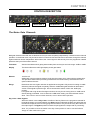
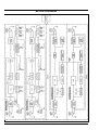
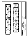
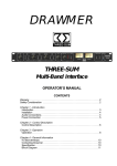
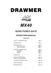
DRAWMER
DSL424
TwoPlusTwo
DYNAMICS
OPERATOR’S MANUAL
CONTENTS
Warranty . . . . . . . . . . . . . . . . . . . . . . . . . . . . . . . . . . . . . . . . . . . . . . . . . . . . . . . . . . . 2
Safety Consideration . . . . . . . . . . . . . . . . . . . . . . . . . . . . . . . . . . . . . . . . . . . . . . . . 2
Chapter 1 - Introduction
Introduction . . . . . . . . . . . . . . . . . . . . . . . . . . . . . . . . . . . . . . . . . . . . . . . . . . . . . . . 3
Installation . . . . . . . . . . . . . . . . . . . . . . . . . . . . . . . . . . . . . . . . . . . . . . . . . . . . . . . . 4
Audio Connections . . . . . . . . . . . . . . . . . . . . . . . . . . . . . . . . . . . . . . . . . . . . . . . . . 4
Power Connection . . . . . . . . . . . . . . . . . . . . . . . . . . . . . . . . . . . . . . . . . . . . . . . . . 4
Chapter 2 - Control Description
The Noise Gate Channels . . . . . . . . . . . . . . . . . . . . . . . . . . . . . . . . . . . . . . . . . . . 5
The Compressor / Limiter Channels . . . . . . . . . . . . . . . . . . . . . . . . . . . . . . . . . . . 6
The Quick Setup Procedure . . . . . . . . . . . . . . . . . . . . . . . . . . . . . . . . . . . . . . . . . 7
Chapter 3 - Operation
The Noise Gate Channels . . . . . . . . . . . . . . . . . . . . . . . . . . . . . . . . . . . . . . . . . . . 8
The Compressor / Limiter Channels . . . . . . . . . . . . . . . . . . . . . . . . . . . . . . . . . . . 9
Chapter 3 - General Information
If a fault develops. . . . . . . . . . . . . . . . . . . . . . . . . . . . . . . . . . . . . . . . . . . . . . . . . . 10
Contacting Drawmer. . . . . . . . . . . . . . . . . . . . . . . . . . . . . . . . . . . . . . . . . . . . . . . 10
Specification . . . . . . . . . . . . . . . . . . . . . . . . . . . . . . . . . . . . . . . . . . . . . . . . . . . . . 11
Block Diagram . . . . . . . . . . . . . . . . . . . . . . . . . . . . . . . . . . . . . . . . . . . . . . . . . . . 12
Session Recall Sheet . . . . . . . . . . . . . . . . . . . . . . . . . . . . . . . . . . . . . . . . . . . . . . 13
COPYRIGHT
This manual is copyrighted 8 2004 by Drawmer Electronics Ltd. With all rights reserved. Under copyright
laws, no part of this publication may be reproduced, transmitted, stored in a retrieval system or translated
into any language in any form by any means, mechanical, optical, electronic, recording, or otherwise, without the written permission of Drawmer Electronics Ltd.
ONE YEAR LIMITED WARRANTY
Drawmer Electronics Ltd., warrants the Drawmer DSL424
TwoPlusTwo Dynamics to conform substantially to the
specifications of this manual for a period of one year from the
original date of purchase when used in accordance with the
specifications detailed in this manual. In the case of a valid
warranty claim, your sole and exclusive remedy and Drawmer’s
entire liability under any theory of liability will be to, at Drawmer’s
discretion, repair or replace the product without charge, or, if
not possible, to refund the purchase price to you. This warranty
is not transferable. It applies only to the original purchaser of
the product.
For warranty service please call your local Drawmer dealer.
Alternatively call Drawmer Electronics Ltd. at +44 (0)1709
527574. Then ship the defective product, with transportation
and insurance charges pre-paid, to Drawmer Electronics Ltd.,
Coleman Street, Parkgate, Rotherham, S62 6EL UK. Write the
RA number in large letters in a prominent position on the
shipping box. Enclose your name, address, telephone number,
copy of the original sales invoice and a detailed description of
the problem. Drawmer will not accept responsibility for loss or
damage during transit.
This warranty is void if the product has been damaged by
misuse, modification or unauthorised repair.
THIS WARRANTY IS IN LIEU OF ALL WARRANTIES,
WHETHER ORAL OR WRITTEN, EXPRESSED, IMPLIED OR
STATUTORY. DRAWMER MAKES NO OTHER WARRANTY
EITHER EXPRESS OR IMPLIED, INCLUDING, WITHOUT
LIMITATION, ANY IMPLIED WARRANTIES OF
MERCHANTABILITY, FITNESS FOR A PARTICULAR PURPOSE,
OR NON-INFRINGEMENT. PURCHASER’S SOLE AND
EXCLUSIVE REMEDY UNDER THIS WARRANTY SHALL BE
REPAIR OR REPLACEMENT AS SPECIFIED HEREIN.
IN NO EVENT WILL DRAWMER ELECTRONICS LTD. BE
LIABLE FOR ANY DIRECT, INDIRECT, SPECIAL, INCIDENTAL
OR CONSEQUENTIAL DAMAGES RESULTING FROM ANY
DEFECT IN THE PRODUCT, INCLUDING LOST PROFITS,
DAMAGE TO PROPERTY, AND, TO THE EXTENT PERMITTED
BY LAW, DAMAGE FOR PERSONAL INJURY, EVEN IF
DRAWMER HAS BEEN ADVISED OF THE POSSIBILITY OF
SUCH DAMAGES.
DRAWMER
DSL424
Dual Channel
Vacuum Tube Compressor
SAFETY CONSIDERATIONS
CAUTION - MAINS FUSE
TO REDUCE THE RISK OF FIRE
REPLACE THE MAINS FUSE ONLY WITH
A FUSE THAT CONFORMS TO IEC127-2.
250 VOLT WORKING, TIME DELAY TYPE
AND BODY SIZE OF 20mm x 5mm.
THE MAINS INPUT FUSE MUST BE
RATED AT 230V=T125mA and 115V=T250mA.
CAUTION - MAINS CABLE
DO NOT ATTEMPT TO CHANGE
OR TAMPER WITH THE
SUPPLIED MAINS CABLE.
CAUTION - SERVICING
DO NOT PERFORM ANY SERVICING.
REFER ALL SERVICING TO QUALIFIED
SERVICE PERSONNEL.
WARNING
TO REDUCE THE RISK OF FIRE OR
ELECTRIC SHOCK DO NOT EXPOSE
THIS EQUIPMENT TO RAIN OR MOISTURE.
Some states and specific countries do not allow the exclusion
of implied warranties or limitations on how long an implied
warranty may last, so the above limitations may not apply to
you. This warranty gives you specific legal rights. You may
have additional rights that vary from state to state, and country
to country.
In the interests of product development, Drawmer reserve the right to modify or
improve specifications of this product at any time, without prior notice.
2
DRAWMER DSL424 OPERATOR’S MANUAL
CHAPTER 1
DRAWMER
DSL424
TWOPLUSTWO DYNAMICS
INTRODUCTION
The DSL424 provides the engineer with a 1U four channel
comprehensive toolbox capable of solving the most
complex dynamic problems. Incorporated in the 1U
package are two industry standard frequency conscious
noise gates and two soft/hard knee compressors with
variable threshold limiting. The channels may be front panel
configured as four individual stand alone processors, a
stereo linked pair of comp/limiters with a stereo linked
pair of gates. Alternatively, any combination of processing
can be achieved by rear panel patching.
The DSL424 combines the gates of the DS404 with the
compressor/limiters of the DL441 to provide a versatile 1U
problem solver invaluable in applications where rack space
is limited.
Recognizing that there are many general applications
which require equipment that is simple to operate, Drawmer
have designed the noise gate stages of the DSL424 utilizing
‘Programme Adaptive’ circuitry. This makes the DSL424
ideally suited for use over a wide range of input signals,
ranging from drums and other percussive instruments
through to vocals, pianos and even complete mixes.
The provision of variable Low-Pass and High-Pass Filters
allows ‘without compromise’ frequency selective gating
with a KEY LISTEN facility enabling monitoring of the filter
setting.
Each gate channel can be operated as HARD - offering
ultra-fast response time, stable triggering and a specialized
release contour which is ideally suited to percussive
material or SOFT - a versatile Expander capable of handling
vocals and sub mixes.
Noise Gate
• Variable High/Low Pass Filters for frequency triggering
• Auto attack
• Variable release
• Switchable range with LED status
• Selectable ‘Hard’ (drums etc.) or ‘Soft’ (vocals etc.)
• 1/4 inch jack Key Inputs
• Key Listen facility
• Slave linking
The compressor section features a highly developed, auto
attack/release system which adapts itself to the
programme material being processed and is equally
effective on individual sounds or complex mixes.
To maximise flexibility, each channel of the DSL424 is
switchable between traditional ratio (hard knee) and
soft-knee operation. Traditionally, soft-knee compressors
are preferable for unobtrusive level control or for the control
of finished mixes, whereas ratio type compressors are
generally considered more successful in creative
applications or where large amounts of gain reduction are
required. By offering a choice of both modes, the DSL424
is capable of outstanding results in a very wide range of
studio and live sound situations. The two channels may
be operated independently or linked for true stereo
operation.
Also included in each channel of the DSL424 is a peak
limiter which allows the user to set an absolute output
signal level that will not be exceeded. If the peak limiter
threshold is exceeded for more than a few milliseconds,
additional gain reduction will be applied to reduce the overall
signal level to within accepted limits without distortion.
Once the peak has passed, the system gain will return to
normal after a period of about one second. This facility is
extremely valuable both in live sound applications, for driver
protection, and in digital recording where an absolute
maximum recording level exists. Furthermore, when
deliberately overdriven, it can be used creatively to produce
level “pumping” effects which can be useful on electric
guitar or rock vocal sounds.
Compressor/Limiter
• Switchable Hard/Soft knee compression with variable
threshold, ratio and output gain
• Auto attack/release
• Variable ‘zero overshoot’ transparent limiter
• High resolution bargraph metering of gain reduction
and input/output level
• Stereo linking
• Balanced +4dB XLR in/out
DRAWMER DSL424 OPERATOR’S MANUAL
3
INSTALLATION
The DSL424 is designed for standard 19" rack mounting
and occupies 1U of rack space. Avoid mounting the unit
directly above power amplifiers or power supplies that
radiate significant amounts of heat and always connect
the mains earth to the unit. Fibre or plastic washers may
be used to prevent the front panel becoming marked by
the mounting bolts.
AUDIO CONNECTIONS
The inputs and outputs are electronically balanced on conventionally wired XLRs (pin 1 screen, pin 2 hot, pin 3 cold and
XLR shell is connected to chassis). The operating level is nominally +4dBu. Balanced use is recommended.
• Interference:
• Ground Loops:
If the unit is to be used where it maybe exposed to
If ground loop problems are encountered, never dishigh levels of disturbance such as found close to a TV
connect the mains earth, but instead, try disconnector radio transmitter, we advise that the unit is operated
ing the signal screen on one end of each of the cables
in a balanced configuration. The screens of the signal
connecting the outputs of the DSL424 to the patchbay.
cables should be connected to the chassis connection
If such measures are necessary, balanced operation
on the XLR connector as opposed to connecting to
is recommended.
pin1. The DSL424 conforms to the EMC standards.
POWER CONNECTION
The unit will have been supplied with a power cable suitable for domestic power outlets in your country. For your own
safety it is important that you use this cable. The unit should always be connected to the mains supply earth using this
cable, and no other.
If for some reason the unit is to be used at a mains input operating voltage which is different to that as supplied, the
following procedure must be carried out :
1: Disconnect the unit from the mains.
2: Remove the two self-tapping screws
that hold the voltage selection switch
cover-plate onto the rear panel.
3: Remove the cover plate and slide the
switch fully to its opposite end.
115V Setting
4: Rotate the cover plate one half turn,
(180 degrees) and refit the two screws.
5: Replace with a correctly rated fuse for
the selected operation voltage.
6: Re-connect to mains power source.
Never disconnect the earth
from the mains supply
4
230V Setting
DRAWMER DSL424 OPERATOR’S MANUAL
CHAPTER 2
CONTROL DESCRIPTION
Noise Gate 1
Noise Gate 2
Compressor 1
Compressor 2
The Noise Gate Channels
Both gate channels of the DSL424 are identical and may be used completely independently or linked for stereo channel
operation. In the linked mode, only the left channel’s controls are functional and serve as master, though the channel
bypass switches remain independent. When linked, the control signal is derived only from the programme material
present at the input of the master channel.
Threshold:
Sets the level below which gating starts to take place and may be set in the range -70dB to +20dB.
Display
The famous Drawmer traffic light display shows gate status
Gate Closed
Hold Time
Gate Open
Release
10mS to 5S.
Additionally, some envelope hold time is built into the system which varies with the release time.
This prevents chatter when processing material with inconsistent decay characteristics and is
quite invisible to the user.
Range
Determines how much gain reduction is applied when the gate is fully closed. A setting of -90dB
effectively silences the signal completely, while the -20dB setting will still allow an attenuated
version of the signal to pass through. We recommend this switch is left in the -90dB (out)
position.
For signals with a high levels of background noise, the very fact of closing down to -90dB can be
disconcertingly noticeable. In such cases the -20dB switch setting can achieve better results.
Note: This control is active on both channels, even in stereo linked operation.
Key Listen / Gate / Bypass
When this switch is set to Key Listen, the effect of the key filters on the programme material is
heard at the output. In normal operation, the Gate position is selected; the filters only affect the way
the DSL424 responds to the incoming programme material - they do not have any direct effect on
the output signal. The Bypass position routes the input signal to the output with no processing.
Note: It is possible to leave the switch in the Key Listen position in order to use the DSL424
simply as a filter rather than a gate.
DRAWMER DSL424 OPERATOR’S MANUAL
5
The Noise Gate Channels cont...
L.F.
25Hz - 10kHz
The Low Frequency filter works by severely attenuating frequencies below the cut-off frequency
selected.
H.F.
200Hz - 35kHz
The High Frequency filter attenuates frequencies above the selected cut-off value. In other words,
when both filters are set, it is the range between the two settings that is allowed to pass.
Ext/Int
In the INT position, this switch causes the gate to respond to the dynamics of the signal being
processed.
In the EXT position, an external audio signal fed to the key input is used to control the gate, making
it possible to gate one sound using another, independent signal.
Gating
Hard/Soft
This button selects between the Hard and Soft modes of operation. In the Hard mode, the DSL424
behaves as a fast, conventional gate while in Soft mode, it performs as a programme adaptive
expander. Hard mode is signified by a red status LED while the Soft mode is identified by a yellow
LED. If two channels are linked, the mode is determined by the master (left) channel and the
Hard/Soft LEDs on the slave channel will extinguish.
Master Link
When the link button is depressed, the gate 2 channel on the right is controlled by the gate 1 left
hand channel. In linked mode, the red status LED beneath the Slave Link switch will be illuminated,
and both the yellow and red HARD/SOFT LEDs of the slave channel will be extinguished. This
assists to show that the only controls of the slave channel that still function are the Key Listen /
Gate / Bypass switch and the Range switch.
The Compressor/Limiter Channels
Both compressor channels of the DSL424 are identical and may be used completely independently or linked for stereo
operation. In the linked mode, only the left hand channel (compressor 1) controls are functional and serve as master
controls, though the channel bypass switches remain independent. In linked mode, the compressor/limiters and peak
limiters of the two linked channels track together to avoid the inevitable image shifting that occurs if the two channels of
a stereo signal are treated independently.
Compressor
Threshold
Determines the input level above which gain reduction will be applied and may be set in the range
-40 to +20dB. When Soft Knee compression is selected, the onset of compression is progressive
over an input range of approximately 15dB, above which level conventional ratio compression is
applied. For this reason, the signal level may appear to fall when the compressor is switched from
Hard to Soft Knee operation and some readjustment of the threshold setting may be required.
Knee
Hard/Soft
Selects Hard or Soft Knee operation. In general, the Soft Knee mode provides the least obtrusive
gain control and is often the preferred setting when treating finished mixes.
6
DRAWMER DSL424 OPERATOR’S MANUAL
Ratio
Sets the final compression ratio that will be applied once the threshold level is exceeded. The ratio
may be continuously adjusted from 1.2:1 to infinity:1 allowing the possibility of true hard limiting.
Gain
During compression, the signal is attenuated depending on the dynamics of the signal. As a result,
gain may need to be applied in order to produce the desired output level. The GAIN control has a
range of -20dB to +20dB. If the limiter is in operation, only increase GAIN until the limiter operates
on signal peaks. Any further GAIN will just cause excessive limiting, thus reducing the effect of the
compressor.
Bypass
This switch will disable the functioning of the Compressor section and the Peak Limiter. If operating
in Stereo Linked mode, both linked compressor channels will be bypassed simultaneously.
Gain Reduction Meter
An eight segment LED bargraph meter continuously monitors the gain reduction applied by the
compressor/limiter over the range 0 to 30dB.
Output Level Meter
This is a 5-segment LED bargraph level meter that monitors the level of the output signal over the
range -10dB to +10dB.
Peak Limiter
Level
This control sets an absolute limit to the level that the output signal will not be permitted to exceed.
This limiter is very fast acting enabling it to control any peaks without audible distortion. If the output
signal is so high as to cause the limiter to operate for more than 20mS, the system gain is
automatically reduced to bring the signal back within range. The system gain is then returned to
normal over a period of approximately one second.
The compressor Gain control should be used to ensure that the peak limiter operates only rarely
if at all if the limiter is to be used purely for peak protection. Alternatively, the unit may be
deliberately driven into limiting to produce creative effects.
THE QUICK SETUP PROCEDURE
Quickly Setup the Gate
• Select the Key trigger source.
• Select Key Listen, and trim down to the desired
frequency for triggering the Gate using the HFand LF
Key filters.
• Select the desired amount of reduction using Range.
Normally fully counter clockwise.
• Set the Attack, Hold. Decay and Range controls. For
a programme with long legato release, then Release will
also need to be long. Eg. Piano with reverb. For material
with much low frequency content, the Attack will need
to be quite slow, unless a ‘click’ is desired.
• Using the Traffic Light LED display, rotate the Threshold
until some gating activity can be seen. As a rule, the
Threshold will need to be about 3dB below the average
input level to both see and hear the dynamic processing.
Quickly Setup the Compressor/Limiter
• Select Hard Knee if compressing percussive tracks and
Soft Knee for vocals.
• Ensure the Limiter control is fully clockwise.
• From the programme material, set the Ratio. The ratio
setting depends on how firmly the signal dynamics need
controlling; as a rule, higher ratios provide a higher
degree of control but also tend to be more audibly
apparent in operation when high levels of gain reduction
are required. In general, we suggest less than 2.5:1 for
vocals, less for full mixes, and more for dynamic single
tracks.
• Using the VU meter and the Compressor Gain Reduction
(GR) meter, rotate the Threshold until some GR activity
can be seen. As a rule, the Threshold will need to be
about 6dB to 10dB below the average input level to both
see, and hear, much change.
• Adjust the Gain to give the desired amount of level on
the VU Meter.
• Adjust the Peak Limiter so that the limiter led only lights
on signal extreme peaks.
DRAWMER DSL424 OPERATOR’S MANUAL
7
CHAPTER 3
OPERATION
The Noise Gate Channels
The unit should be connected in-line with the signal to be
processed via suitable insert points. Ensure, where
possible, that the insert send and return level on your
console approximately matches the operating level of the
DSL424.
For mono use, each channel may be considered as being
completely independent and set up accordingly. For use
with stereo signals, all setting up is then done using the
noise gate 1 (left) channel's controls.
For percussive material such as drums, fast synthesised
sounds or percussive bass guitar, the Hard mode of
operation will give the fastest response. However, with
material having a slower attack, the Hard setting may
produce transient clicks at the beginning of sounds in
which case the Soft setting may produce better results.
Initially, the Low filter should be set fully anti-clockwise
while the High filter should be set fully clockwise. This will
allow the full audio spectrum of the input programme to be
monitored by the side-chain control circuitry. Set the
Range control to -90dB and the output selector switch to
Normal.
With the release control set at its mid-way position, Range
set to -90dB and with suitable programme material fed
into the DSL424, increase the Threshold level from its anticlockwise position until the gate starts to operate. This
will be indicated by the activity of the traffic light LEDs
and you should also hear the effect on the outputs signal
in that pauses in the programme will now be silent. If the
threshold setting is too high, the gate will start to cut out
wanted pieces of programme so you should adjust it to as
low a setting as possible consistent with the effective
removal of low level noise. If the ends of sounds are
obviously being truncated, then a longer release time may
help. On the other hand, if unwanted noise is audible after
the wanted sound has ended, a shorter release time may
well be more appropriate.
There are circumstances when the programme material is
corrupted not only by unwanted random noise, but by some
other sound. For example, in a multi-miked drum kit setup,
some hi-hat will inevitably leak into the snare mic, some
snare drum into the kick drum mic and so on. Equally,
when recording on location, you may experience problems
due to wind or traffic noise or close-by conversation. If the
unwanted noise is different in pitch to the wanted sound,
8
it is often possible, by using the Key Listen facility, to use
the filters to 'tune' into the wanted sound while excluding
as much of the unwanted sound as possible. Used
carefully, these filters can significantly increase the gate's
immunity to false triggering.
LINKED OPERATION
It is important to note that when linked, the control signal
is derived entirely from the noise gate 1 channel. This
means that stereo signals where one channel differs
significantly from another may fare better if the channels
are not linked.
On the other hand, this mode of linking is very powerful in
synchronizing the start and finish of sounds, a typical
application being to tighten up backing vocals. If one singer
tends to finish notes on time while the other hangs on too
long, the correct version can be used as the master to
ensure that both finish at the same time. Similarly, one
sound can be used to gate another without having to resort
to patching in an external key signal. An example might
be to gate a low frequency tone from a bass drum signal
and then add this gated tone to the drum sound to add
depth.
DIFFICULT MATERIAL
As with any other gate, noise can only be removed during
pauses in the wanted material. If the noise contamination
is serious enough to be evident even during moderately
loud programme material, then simple gating will do little
to help. Indeed, the very fact that the gate produces nearperfect silence during pauses can make the noise content
of the programme material seem even worse. In marginal
cases, setting the range control to -20dB rather than 90dB will adequately reduce the noise during pauses but
not sufficiently to cause an unacceptably dramatic change
in noise level as the gate opens and closes.
More sophisticated processors such as the Drawmer
DF330 are better able to cope with excessive noise as
they adaptively filter the programme so as to mask the
noise during low level passages or where there is little
high frequency content present to mask it. However, the
key filters in the DSL424 may also be used to good effect,
particularly in situations where the wanted signal does
not occupy the full audio spectrum.
DRAWMER DSL424 OPERATOR’S MANUAL
Taking the example of the electric guitar, this produces
little below 100Hz or above 3kHz so setting one channel
of the DSL424 to Key Listen mode will enable you to use
the filters to exclude much of the amplifier hum at the low
end and hiss at the top end while having little effect on the
sound of the guitar. Surprisingly, the same is true of the
acoustic guitar; (even a bright-sounding steel-strung
model), and the filters can be used to reduce the effect of
string squeak or the player's breathing.
Other applications of the filter section include shaping DI'd
electric guitar sounds to remove unpleasant overtones and
to simultaneously clean and warm up digital synthesizer
sounds. While we should always endeavour to get the
highest quality of programme material at source, every
engineer is occasionally confronted with inferior material
from sources beyond his control. Conventional equalisers
seldom have a sharp enough response to duplicate the
function of the Key filters which invariably results in the
wanted material being filtered as well as the unwanted
noise. Once a signal has been filtered in this way, it may
also be processed by the second channel of the DSL424
to apply conventional gating.
The Compressor / Limiter Channels
The unit should be connected in-line with the signal to be
processed via suitable insert points. For mono use, each
channel may be considered as being completely
independent and set up accordingly. For use with stereo
signals such as complete mixes or submixes, the
channels should be switched to Stereo Link mode and all
setting up done using the compressor 1 (left compressor)
channel controls.
Compressing during a mix does increase the subjective
level of tape and other background noises during pauses
and quiet passages as maximum gain is applied when
the signal level is minimum. For this reason, it is unwise
to use more compression than is strictly necessary.
However, using the DSL424 the signal can be patched
through the gate, either before or after the compressor, to
remove any unrequired sounds.
Setting up is simplified by the auto attack and release
system which continually optimises the attack and release
times to suit the dynamics of the material being processed.
The ratio setting depends on how firmly the signal dynamics
need controlling; as a rule, higher ratios provide a higher
degree of control but also tend to be more audibly apparent
in operation when high levels of gain reduction are
required. In general, a higher compression ratio may be
used when in Soft Knee mode without compromising the
subjective sound quality.
Finally, the Gain control may be set to provide the required
output level using the level meter as a guide. Avoid running
at very high output levels as this reduces the available
amount of signal headroom and could lead to distortion in
extreme cases. Once the gain is correct, the Peak limiter
Level control should be adjusted so that the limiter LED
only lights briefly on extreme signal peaks. Alternatively,
the Peak limiter Level may first be set to the desired value
and then the compressor Gain control adjusted to ensure
minimum limiter activity.
Having selected Hard or Soft Knee and set a suitable Ratio,
setting up is simply a matter of adjusting the Threshold
control until the desired amount of gain reduction occurs.
This is judged partly by ear and partly by observing the
gain reduction meter. Normally a maximum gain reduction
of between 8dB and 12dB will be adequate. If more gain
reduction appears necessary, it is worth considering
applying a conservative degree of compression during
recording and then further compression while mixing.
The Peak limiter has no bypass control, but turning the
Level control fully clockwise will effectively prevent the
limiter from operating.
Compressors are often accused of dulling the sound being
processed, but the auto circuitry in the DSL424 has been
designed to allow transient sounds to pass through
cleanly, thus maintaining the clarity and transparency of
the original source. Soft Knee operation is usually
preferable when unobtrusive gain control is required.
DRAWMER DSL424 OPERATOR’S MANUAL
9
CHAPTER 4
GENERAL INFORMATION
It is the responsibility of the installer to ensure that the continuous power rating of the speakers is not exceeded, as Drawmer
Electronics Ltd will not accept any responsibitlity for speaker damage caused by incorrect settings.
IF A FAULT DEVELOPS
CONTACTING DRAWMER
For warranty service please call Drawmer Electronics Ltd. or
their nearest authorised service facility, giving full details of
the difficulty.
Drawmer Electronics Ltd., will be pleased to answer all
application questions to enhance your usage of this
equipment. Please address correspondence to:
A list of all main dealers can be found on the Drawmer
webpages.
On receipt of this information, service or shipping instructions
will be forwarded to you.
No equipment should be returned under the warranty without
prior consent from Drawmer or their authorised representative.
For service claims under the warranty agreement a service
Returns Authorisation (RA) number will be issued.
Write this RA number in large letters in a prominent position
on the shipping box. Enclose your name, address, telephone
number, copy of the original sales invoice and a detailed
description of the problem.
Authorised returns should be prepaid and must be insured.
All Drawmer products are packaged in specially designed
containers for protection. If the unit is to be returned, the original
container must be used. If this container is not available, then
the equipment should be packaged in substantial shock-proof
material, capable of withstanding the handling for the transit.
10
Drawmer (Technical Help line)
Coleman Street
Parkgate
Rotherham
S62 6EL
UK
Alternatively contact us by E-mail on :
[email protected]
Further information on all Drawmer dealers, Authorised service
departments and other contact information can be obtained
from our web pages on:
http://www.drawmer.com
DRAWMER DSL424 OPERATOR’S MANUAL
DSL424 TWOPLUSTWO DYNAMICS
DATA SPECIFICATION
NOISE GATE CHANNELS
COMPRESSOR / LIMITER CHANNELS
INPUT
INPUT
Input Impedance
20k Ohms (Balanced)
Max Input level
+21dBuB (+17dB ref. +4dBu)
Input Impedance
Key Input Impedance
20k Ohms (Balanced)
20k Ohms (Unbalanced)
Max Input level
Max Key Input Level
+21dBu
+21dBu
OUTPUT
Output Impedance
50 Ohms (Balanced)
Output Level
Bandwidth
+21dBu
<10Hz to 22kHz -1dB
Floor Level
-90dB, (or -20dB)
OUTPUT
Output Impedance
50 Ohms (Balanced)
Output Level
Bandwidth
+20dBu
<12Hz to 35kHz -1dB
Crosstalk
@10kHz Better than -80dB
@20kHz Better than -75dB
Output Balance
Better than 40dB 20Hz to 10kHz
Noise at Unity Gain ref. +4dBu
Noise
Wideband 22Hz-22kHz CCIR
AV
-91dB
-97dB
RMS
-89dB
-96dB
IEC A Q-Pk CCIR
-97dB -100dB
-86dB
-99dB
Wideband 22Hz-22kHz CCIR
IEC A Q-Pk CCIR
AV
-90dB
-98dB
-99dB -100dB
RMS
-89dB
-96dB
-97dB
-88dB
-98dB
Distortion
Distortion
100Hz
Gate Open with +4dB Input
<0.04%
1kHz
10kHz
<0.04% <0.04%
100Hz
Unity Gain, +4dB Input
Power Requirements
115Volt or 230Volt at 50-60Hz, 15VA
Fuse Type
CONFORMS TO IEC127-2.
Fuse Rating
230V=T250mA, 115V=T125mA.
Case Size
482mm (w) x 44mm (h) x 190mm (d)
Weight (incl packaging)
3.7 Kgs
DRAWMER DSL424 OPERATOR’S MANUAL
<0.02%
1kHz
10kHz
<0.015% <0.035%
11
BLOCK DIAGRAM
DSL424 ver 01 B 29/06/04
12
DRAWMER DSL424 OPERATOR’S MANUAL
DRAWMER DSL424 OPERATOR’S MANUAL
13
dB
10
1K
3K5
1K
2K
200
500
500
250
INT
Hz
6
:1
3
1
RATIO
2
20
10
20
GAIN
dB
0
BYPASS
20
10
OUTPUT LEVEL
5
0
5 10
10
dB
0
5
LEVEL
dB
10
DRAWMER ELECTRONICS LTD ~ Coleman Street
Rotherham ~ S. Yorkshire ~ UK
© COPYRIGHT DRAWMER ELECTRONICS LTD 2004
1S
16
LINK
15 Master
LINK
Master
dB
10
25
6
1.2
2
4
HARD SOFT
Session No.
2
200
:1
3
5
20
10
1 dB 10
RATIO
Tape Location
Artist
Date
3K5
1K
2K
Hz
HARD SOFT
35K
0
5K
10
10K
GATING
2K
20
10
GAIN
dB
0
dB
0
5
LEVEL
dB
10
PEAK
16
15
1S
ON
OFF
DSL424
TwoPlusTwo
DYNAMICS
DRAWMER
90dB 20dB
5S
4S
GATE
BYPASS
RANGE
2S
KEY
LISTEN
OUTPUT
RELEASE
10mS
.1S
60
50
40
70
20 30
THRESH
20
10
BYPASS
20
10
OUTPUT LEVEL
5
0
5 10
L.F. FILTER H.F.
Hz
1K
INT
500
500
250
COMPRESSOR 2
50
150
EXT
KEY SOURCE
100
1.5
KNEE
30
20
40
THRESH
20
10
0
GAIN REDUCTION
30 20 15 10
90dB 20dB
5S
4S
GATE
RANGE
2S
BYPASS
OUTPUT
KEY
LISTEN
RELEASE
10mS
PEAK
60
.1S
50
40
70
20 30
THRESH
20
10
DSL424
5
dB 10
HARD SOFT
35K
0
5K
10
10K
GATING
2K
Session Recall
HARD SOFT
1.2
2
4
COMPRESSOR 1
L.F. FILTER H.F.
Hz
150
1.5
KNEE
30
20
40
THRESH
20
10
0
GAIN REDUCTION
30 20 15 10
25
100
50
EXT
KEY SOURCE