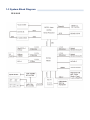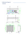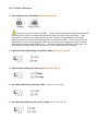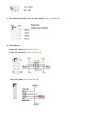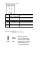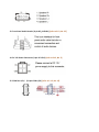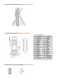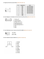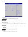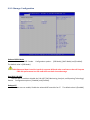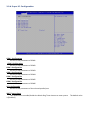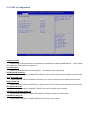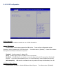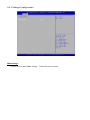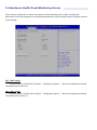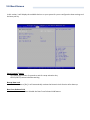
1
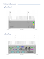
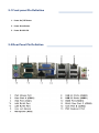
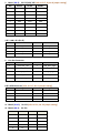
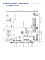
FES2215 Fanless Embedded System User Manual FES2215: Fanless Embedded System Atom D2550 Dual Core 1.86GHz Processor 14628 Central Ave, Chino, CA 91710 tel:909.597.7588, fax:909.597.1939 © Copyright 2013 Acnodes, Inc. All rights reserved. Product description and product specifications are subject to change without notice. For latest product information, please visit Acnodes’ web site at www.acnodes.com. Copyright This publi cati on c ontains inform ation that is prot ected by copyright. N o part of it m ay be reproduced i n any form or by any m eans or used to make any transform ation/adaptation without the prior written permission from the copyr ight holde rs. The manufacturer reserves the right to revise this publication and m ake changes to its contents at any time, w ithout obl igation to noti fy any person or entity of such revisions or changes. ©201 3. Al l Rights Reserved. Trademarks Al l tradem arks and registered trademarks of products appearing in this m anual are the properties of their respective holders. Notice: 1. The chan ges o r modification s n ot expressly a ppro ved by th e p arty r espo nsible fo r compliance cou ld void th e user ’s auth ority to op erate t he eq uipment . 2. Shielded int erfa ce ca bles must be used in or de r to comply wit h t he emission limits. Static Electricity Precautions It is quite easy to inadvertently dam age the system board, c omponents or devices e ven before i nstal ling them i n your system unit. Static electri cal discharg e can dam age computer com ponents wi thout causing any signs of physi cal dam age . You must take extra care in handl ing them to ensure against el ectrostatic bui ld up. 1. To prevent electrostatic bui ld up, le ave the system board i n i ts anti-static bag unti l you are ready to install it. 2. Wear an antistatic wrist st rap. 3. Do all preparation w ork on a stati c-free surface. 4. Hold the device only by its edges. Be careful not to touch any of the components, contac ts or connections. 5. Avoi d touching the pins or contacting all m odul es and connectors. Hold modules or connectors by the ir ends. Impo rt ant: Elect rost atic d ischa rge (ESD) can damage you r p rocessor, disk dr ive an d ot her compo nents. Perform t he up grade instru ct ion pr ocedures describ ed at an ESD wor kstation on ly. If such a sta tion is no t availab le, yo u can provide some ESD protection by wear in g a n ant istatic wrist st rap and attaching it to a met al part of the system chassis. If a wr ist strap is una vailab le, es tab lish an d maintain contact with the syst em chassis th roug hout any p rocedures req uiring ESD protection. FES2215 Fanless Embedded System Safety Measures To avoid dam age to the system : • Use the correct A C input vol tage range to reduce the risk of ele ctric shock. • Unplug the power cord before rem oving the system chassis cover for install ati on or servi cing. After instal lation or servicing, cover the system chassis bef ore plugging the power cord. Batte ry: • Dange r of expl osion if battery incorrectly replaced. • Repl ac e only w ith the same or e quival ent type re com mend by the manufacture r. • Dispose of used batteries according to l ocal ordinance. Warranty 1. Warranty does not cover dam ages or fai lures caused by m isuse of the product, inabili ty to use the product, unauthorized replacem ent or any kind of alterations of components and product specif ications. 2. The warranty i s voided if the product has been exposed to physi cal abuse , improper instal lation, a ny kind of modific ation, acc idents or unauthorized repair of the product. 3. Unl ess otherwise instructed in this user m anual, the user m ay not, under any ci rcum stances, attem pt to perform servi ce , adjustm ents or repairs on the product him se lf, whether the product is sti ll covered by warranty or not. It must be returned to the place i t was purchased at, the fa ctory or an authorized se rvic e agency for any re pai r work. 4. We w il l not be l iabl e for any indi re ct, spe cial, incidental or conseque nt damages to the product that has be en m odif ied or alte red. 14628 Central Ave, Chino, CA 91710 tel:909.597.7588, fax:909.597.1939 © Copyright 2013 Acnodes, Inc. All rights reserved. Product description and product specifications are subject to change without notice. For latest product information, please visit Acnodes’ web site at www.acnodes.com. FES2215 Fanless Embedded System Table of Contents Copyright ................................................................. ................................................. Tradem arks ............................................................................................................... Static Electricity P re cautions .................................................................................... Safety Measures ....................................................................................................... Warranty ................................................................................................................... 2 2 2 3 3 Chapter 1 : Introduction 1-1 Overview.............................................................................................................. 1-2 P roduct Spec ifi cati on........................................................................................... 1-3 System Block D iagram ............................................................ ............................. 1-4 Me chanical D iagram ...................................... ..................................................... 1-5 Front and Re ar I/O…............................................................... ............................. 5 6 8 9 10 Chapter 2 : Pin De finition & Jumper Settings 2-1 Front panel P in Definition…………………………………………………….............…………… 2-2 Rear Pane l P in Definition……………………… …………………………………………… …………. 2-3 Internal P in Definition & Jumper Settings………………………………… ……………………. 2-3.1 Main Board Top V iew………………….………………………………………………………. 2-3.2 Mai n Board P in Definiti on…………….…………………………………………… …………. 2-3.3 Jum per Setting…………………………….………………………………………………………. 11 11 14 14 15 16 Chapter 3 : UEFI Setup Utility 3-1 Introduction……………………….……………………………………………… …………………………. 3-2 Mai n Screen…………………………………………………………………………………….…………… 3-3 Advanced Sc reen……… ……………………………………………… …………………………….…… 3-4 Hardware Health Event M onitoring Screen..……………………………………… .………… 3-5 Boot Screen...…………… …………………………………………………………………………………… 3-6 Security Screen……………………………………………………………………………………………… 3-7 Exi t Sc ree n…………………………………….……… ……………………………………………………… 23 24 25 33 34 35 36 Chapter 4 : Installation Guide 4-1 Me mory Modules (SO-DIM M).………………………… ……… ……………………………………. 4-2 Expansion Sl ot ( PCI Slot)……………………………………………………… ………………………… 37 38 14628 Central Ave, Chino, CA 91710 tel:909.597.7588, fax:909.597.1939 © Copyright 2013 Acnodes, Inc. All rights reserved. Product description and product specifications are subject to change without notice. For latest product information, please visit Acnodes’ web site at www.acnodes.com. FES2215 Fanless Embedded System Chapter 1: Introduction 1-1 Overview A cnodes’ FES 22 15 is an outstanding and r eliable Fan-less embedded sy st em w it h high per for mance and low power consump tion r emained. The new FES22 15 pro vides cust omer a choice of At om D2 550 / N2800 / N2600 Proces sor, depends on t he model being selected. FE S2215 has applied by t he r ecent launched At om™Pr ocessor D2550 Dualcor e 1.86 GHz Pr ocessor, w hich deliver ies enhanced per for mance in mult i-media capability on t he mar ket at t he pr esent m oment and i t of fer s to reach t he maximum m emor y size up to 4 GB DDR3800/ 1066 w hile as t he gr aphic clock speed of 64 0 MHz. FES2215 suppor ts for dual display of VGA and HDMI . Fu rt her mor e, w hile as t he new FES2215 is equipped of NM10 South Br idge Chipset , w hich deliver ies high speed st or age int er face t hat suppor ts for fast er data tr an sferr ing r ate as to increase eff iciency I n order to meet t he netw or k stability, t he FES2215 ser ies use tw o Realt ek 81xx 100/ 1000 Mbps LAN w it h Wake-On LAN & DMI to suppor t and maintain Eth er net funct ion. The syst em designed w i th tw o DB-9; one supp or ts for RS-232/ 422/ 485 and one suppor ts for RS-232 int er face, an d one RJ-45 sup por ts for RS-232. Ther e are th ree of DB-9 for RS-232 reser ved for op tional expansion availability. A softw ar e pr ogr amming Watchdog (WDT) w it h timer r ange f rom 1 to 255 seconds is enabled in Pi pal 2215. For t he audio output , t here h as occupied w it h an ALC662 for sp eak er. The pow er supply is capable for DC pow er input of 12V or 24V. The power con sump tion is able to r each up to 22 W in maximum. The syst em is valuable for all t he embedded ap plications, and also w ell sup por t w it h t he Window 7, W indow s XP and Linu x Oper ation syst em. The new FES2215 is not only capable and r eliable to of fer you an unprecedent ed exper ience w it h extr emely high gr aphic perfor mance along w it h remainin g low on pow er consumpt ion but also pr esent an outstanding cost-competitive advantage in t he mar ket . 14628 Central Ave, Chino, CA 91710 tel:909.597.7588, fax:909.597.1939 © Copyright 2013 Acnodes, Inc. All rights reserved. Product description and product specifications are subject to change without notice. For latest product information, please visit Acnodes’ web site at www.acnodes.com. 1-2 Product Specification Processor & Chipset Sup por t Atom D2 550 D ual-core 1.86 GHz low p ower Pro cessor NM 10 South Bridge Chip set Graphic E ngine Graphic core 640 Mhz Sup por t AVC/ H.264, VC1/ WMV9, MPEG2 HW engine Blu -Ray Su ppor t HD CP 1.3ans PAVP 1. 1C c ontent protection sup port Sup por t M icro soft DXVA 2.0 an d Overlay DD MS C OPP and PVP-OP M sup por t Enabling Key ISVs-Corel, CyberLink, ArcSoft Sup por ts Op enGL 3.0 an d Microsoft DirectX 9 System Mem ory 2 SODIMM Socket, up to 4 GB 800 / 1066 MHz DD R3 Memo ry Display Function Sup por t VGA + HDMI dual disp lay HD MI, VGA su ppo rt 1920 x 1200 (1080P) resolution BIOS AM I BIOS. Support Power On Aft er Power failure Expansion 1 M ini-PCI-E expansio n slot Note: may install mSATA SSD, Wireless L AN module Audio AL C 662 HD Cod ex sup port, 2W amplifier for Sp eaker ou t Ethernet 2 Realtek 81xx 10 0/1000 Mbp s LAN with Wake-On-LAN & DMI Disk Drive S torage 2.5” SATA HDD & 1 Mini-PCI-E mSATA (sh are Mini-PCI-E slot) RS -232/422/485 Support Default: 2 D B-9 as 1 for RS-232/422/485 & 1 for RS-232, 1RJ-45 fo r RS-232 Op tio nal Expansion: 3 DB-9 for RS-232 Watchdog T imer Programmable WD T from 1 to 255 seconds/ minu tes Power On/Off Mode Push bu tton AT/ATX po wer on / off RTC Alarm Power on Front Panel Extend I/O Ports Power & HDD Led. Power & System, Power & Reset b utton Rear Panel E xtend I/O Ports Screw-Lock DC po wer input con nector 2 DB-9 as 1 for RS-23 2/422/485 & 1 for RS-232, 1 RJ-45 for RS-232 VGA + HD MI display interface 4 USB , 2 RJ-45 100/1000 Mbit LAN co nnector 1 Mic ro p ho ne-in, 1 Lin e-o ut co nnector 1 PS/2 Keyb oard an d 1 PC/2 M ouse co nnector Rear Panel Optional I/O 3 DB-9 for COM 4, 5, 6 RS-232 por t o r 2 COM + 1 Digital I/O 1 DB-25 for Printer por t Power S uppl y DC 12V or 24V inp ut. 12VFC/ 2. 5A, 24VDC/1.25A, AT/ATX power type Power adapter : AC to DC , D C 12V/5A 60W ( Optional ) Power Consum ption (with HDD ) Typ ical Po wer Con sumption : 17W Maximum Po wer Con su mption: 22W Environment Operation Temp eratu re: - With extend temp eratu re HDD: -20°C~60°C - With extend temp eratu re SSD: -20°C~60°C Storage Temperature: -40°C~8 5°C Relative Humidity: 10%~90% (Non -con densing) M echanical Dimen sion W x H x D : 200 mm x 89.83 mm x 18 5.5mm (7.87'' x 5.34'' x 7.30')' Mou nting: Desk/Wall M ount Con stru ctio n: Aluminum h ousing Weight (Net/ Gross): 4. 4KG (9.68lb)/ 5.0KG (10. 4lb) Certification CE/FCC Class A OS S upports Windows 7, Win XP, L in ux 1-3 System Block Diagram FE S 2215 1-4 Mechanical Diagrams FES 2215 1-5 Front & Rear panel Front Panel Rear Panel 2-1 Front panel Pin Definition 1. Power On/ Off Button 2. Power Reset Button 3. Power & HDD LED 2-2 Rear Panel Pin Definition 2. COM 1 (DB-9): RS-23 2/ 422/ 4 85 [refe r to P.17-18, N o. 8 jumper setting] PIN RS-232 R S-422 R S-486 1 D CD# TX+ RT X+ 2 RXD RX+ Not U sed 3 T XD TX- RTX- 4 DT R# RX- Not U sed 5 GND GND G ND 6 DSR# Not Used Not U sed 7 R TS# Not Used Not U sed 8 C TS# Not Used Not U sed 9 RI# Not Used Not U sed 4 & 5. LAN 1 & 2 (R J-45) PIN D efi nition PIN Definition 1 La n_TX1+ 2 Lan_TX1- 3 La n_TX2+ 4 Lan_T X3+ 5 7 Lan_TX3La n_TX4+ 6 8 Lan_TX2Lan_TX4- 6. Line-Out Connector PIN D efi nition PIN Definition 1 LINE_OU T _Left 2 LI NE_OU T_Right 3 AUDI O_AGND 4 AUD IO_AGND 5 LINE_IN_Left 6 LI NE_IN_R ight 7 AUDI O_AGND 8 AUD IO_AGND 9 Mi cro phone_IN1 10 Micro phone _I N2 8 & 9. U SB Connector [re fer to P.1 7, No. 10 jumper se tting] PIN 1 2 3 Si gnal 5V DD+ PIN 5 6 7 S ignal 5V DD+ 4 GND 8 G ND 11 . COM 3 (RJ-4 5): RS-23 2 [refer to P.2 1, No. 22 jumper setting ] 12 . COM 2 (DB-9): RS-232 Pi n Defini tio n Pi n Defin iti on 1 D CD 2 RX 3 TX 4 DT R 5 GND 6 D SR 7 RT S 8 CT S 9 RI 2-3 Internal Pin Definition & Jumper Settings 2-3.1 Main Board Top View 2-3.2 M ain Board P in Definition 2-3.3 Jumper Settings 1. Clear CM ON S Jumper (CLRCMOS1 ) [refer to P.13, N o. 1 6] It allows you to clear t he data in CM OS. To clear and reset the system parame ters to default se tup, please turn of f the computer and unpl ug the pow er cord f rom the pow er supply. Af te r wai ting for 15 seconds, use a jumpe r cap to short pin 2 and pin 3 on CLRCM OS1 for 5 seconds. However, please do not clear the CMO S right af ter you update the BIO S. If you ne ed to clear the CM OS when you just fi nish updating the BIOS, you m ust boot up the system f irst, and the n shut it down bef ore you do the cl ear-CMOS action. P lease be noted that the password, date, t ime , use r def ault profi le and MAC address w ill be cleared only if the CM OS battery is rem oved. 2. Digital I/O He ader PW R Setting (3 -pin JGPIO_PWR1 ) [refer to P.13, No.14 ] 3. PWR-On M ode Setting (3 -pin PWR_ JP1 ) [refer to P.1 3, No.17 ] 4. Panel V DD PWR Setting (3-pin PN L_PWR1) [refe r to P.13, N o.26 ] 5. Panel BackLight PWR Setting (3-pin BKT_PWR1) [refer to P.13, N o. 27] 7. Panel Resolution Se lection (1 2-pin JLVD_ GPIO1) [refer to P.1 3, N o. 2 9] 8. SET COM Por ts (10 -pin SET_ CM 1,2 ) [refer to P.1 3, No. 1 ] (10 -pin SET_ CM 4,5 ,6) [refer to P.13 , N o. 20 ] (5 -pin SET_ CM 3) [refer to P.13, N o. 30 ] (COM 1 Pin1 & Pin 9 Function Setting) Item Pin 1 Fun ction Connector SET_COM1 Jumper S etti ng Config. 1 Provide +12V Power Source Pi n 1 & Pi n 3 short, Pin 5 & 7 & 9 NC Config. 2 Provide +5V Po wer Source Pi n 3 & Pi n 5 short, Pin 1 & 3 & 9 NC Config. 3 Provi de DCD# Function Pi n 7 & Pi n 9 short, Pin 1 & 3 & 5 NC Item Pin 9 Fun ction Connector SET_COM1 Jumper S etti ng Config. 1 Provide +12V Power Source Pin 2 & Pin 4 s hort, Pin 6 & 8 & 10 NC Config. 2 Provide +5V Po wer Source Pin 4 & Pin 6 s hort, Pin 2 & 4 & 10 NC Config. 3 Provide R I# F unction Pin 8 & Pin 10 short, Pin 2 & 4 & 6 NC 9. SATA 2 Connectors (SATA2_1) [refer to P.1 3, No. 8 ] (SATA2_2) [re fer to P.13 , N o. 10 ] 10. USB 2.0 Ports (4-pin USB 4,5) [refer to P.13, N o. 11 ] (4-pin USB6 ) [refer to P.13, N o. 12] 11. System Panel Header (9-pin PANEL 1) [refer to P. 13, N o. 15] Connect the powe r switch, rese t switch and system status indicator on the chassis to this header according to the pin assignments below. N ote the positive and ne gative pins before conne cting the cables. - PWRBTN (Power Switch) - RESET (Reset Switch) - PLED (Syste m Powe r LED) - HD LED (Hard D rive Ac tivity L ED ) 13. Front Panel Audio Header (9-pin HD_ AUDIO1) [refer to P.13, No. 25 ] 14. DC 12V Power Connector (4-pin DC 12V 1) [re fer t o P.1 3, No. 3 ] 15. COM Port 4 ,5 ,6 (10-pin COM 4,5,6) [refer to P. 13 , No. 19 ] 16. Print Port Header (25-pin LPT1) [re fer to P.13, N o. 9] 17. LVD S Con (40 -pin LV DS1) [re fer to P.13, N o. 2] 18. Output Power (4-pin SATA_ PWR1 ) [refer to P.13, No. 7] 19. Digital I/O He ader (10 -pin JG PIO1) [re fer to P.13 , No. 13 ] 20. Panel Brightness and Speaker Volume Control (7-pin BLT_VOL1) [refer to P.1 3, No. 2 1] 21. Panel BackLight Inve rte r Connector (6-pin BLT_PWR2) [re fer to P.1 3, No. 2 2] 22. RJ-45 COM Port C (8-pin COM Port C ) [refer to P.13, N o. 1 1] Chapter 3: UEFI Setup Utility 3-1 Introduction This se ction explains how to use the U EFI SETUP U TILITY to configure yours syste m. The UEFI chip on the m otherboard stores the U EFI SETUP U TILITY. You may run the UEFI SETUP U TILITY w hen you start up the computer. P lease press <F2> or <Dele te > during the Power-On-Self-Test (P OST) to enter the U EFI SETUP U TILITY, otherwi se , P OST wi ll continue wi th its test routines. If you wish to enter the UEFI SETUP U TILITY afte r PO ST, restart the system by pressing <Ctl > + < Alt> + <Del ete >, or by pressing the reset button on the syste m chassis. You m ay also resta rt by turning the syste m off And then ba ck on. 3-1.1 UE FI Menu B ar The top of the screen has a menu bar w ith the foll ow ing sel ections: M ain: For setting system tim e/date inform ati on OC Tweaker: For over-clocki ng configurations Advanced: For advanced system configurations H/W M onitor: Displays current hardware status Boot : For configuring boot setti ngs and boot pr iori ty Security: For se curi ty settings Exit: Ex it the current scre en or the U EFI SETUP UTILITY Use <? > key or < ? > key to choose among the sele cti ons on the menu bar, and use < ? > key or <? > key to m ove the cursor up or down to selec t items, then press <Enter> to get into the sub screen. You can also navigate with a mouse. 3-1.2 Navigation Keys Pl ease che ck the following table for the functi on descriptions of each navigati on keys. 3-2 Main Screen Whe n you enter the UEFI SETUP UTILITY, the Main screen wil l appear and display the syste m ove rview. 3-3 Advanced Screen In this se ction, you m ay set the confi gurati ons f or the foll owing i tem s: CPU Configuration, Chipset Configuration, Storage Conf igurati on, Super IO Configuration, A CPI Configuration, U SB Conf iguration and Voltage Conf iguration. Se tting wrong values in this se ctio may cuase the system to malfunction. Instant Flash Instant Flash is a UEFI f lash utili ty em bedded in Flash ROM. This conve nie nt UEFI update tool allows you to update system UEFI w ithout entering operating syste ms first l ike M S-DO S or W indows®. Just launch this tool and save the new UEFI fil e to your U DB flash dri ve, fl oppy disk or hard drive, then you can update your U EFI only in a fe w cli cks wi thout pre paring and addi ti onal f loppy diskette or othe r com plicated f lsh uti lity. Ple ase be noted that the USB f lash drive or hard drive must use FAT32/16/12 fi le syste m. If you execute Instant Flash utility, the util ity wil l show the UEFI fi les and the ir respe ctive information. Se lect the proper U EFI f ile to update your UEFI, and re boot your system after U EFI update proc ess completes. 3-3.1 CPU Configuration Intel Hyper T hre ading Technology To enabl e this feature, it requi res a c ompute r system with an Intel processor that supports HyperThreading technol ogy and an operating syste m that includes optimization for this te chnol ogy, such as Mi crosoft® Wi ndow s® 7. Se t to [Enabled] if using Mi crosoft® Wi ndow s® 7. N o-Execute M emory Protec tion No-Execution (N X) M emory P rote ction Technology is an e nhance ment to the IA-32 Intel A rchitecture . An IA -32 processor with “No Execute (NX ) M em ory P rotection” can prevent data pages from being used by m al icious software to exe cute code. 3-3.2 Chipset Configuration Set Pane l Type by Use this to c onf igure Set P anel Type.The Default value is [UEFI Setup]. Panel Type Sele ction Use this to sele ct panel type . The default va lue i s [1366 x768/ 18-bi t/ 1 -ch/LED ]. ACPI H PET Table Use this item to enable or disable ACPI HPET Table. The defaul t value i s [Enabl ed]. Pl ease se t this option to [Enable d] if you plan to use this motherboard to subm it W indows® certi fication. Restore on AC/Power Loss This al lows you to set the powe r state after an unexpected A C/power loss. If [Pow er Off] is selected, the AC/ pow er remai ns of f w hen the powe r re covers. If [P owe r On] is sele cted, the A C/power resumes and the system starts to boot up when the pow er recovers. Onboard HD Audio Sel ect [Audio], [Enabl ed] or [Disabl ed] for the onboard HD Audio feature. If you select [Auto], the onboard HD Audio wi ll be disabled when PCI Sound Card is plugged. Front Panel Sel ect [Auto] or [Disabled] for the onboard HD A udi o Front Pane l. Onboard LAN 1 This al low you to enable or di sable the “Onboard LA N 1” feature. Onboard LAN 2 This al low you to enable or di sable the “Onboard LA N 2” feature. 3-3.3 Storage C onfiguration Onboard SATAII M ode Use this to sele ct SATA 2 m ode. The default value is [IDE Mode ]. Confi gurati on options: [IDE Mode], [AHCI Mode] and [D isabled]. ACHI (Advanced Host Controller Interfac e) suppor ts NCQ a nd other new features that will improve SATA disk perfor mance but IDE mode does not have these advantage. Hard Disk S.M .A.R.T Use this item to enable or disable the S.M.A.R.T ( Sel f-Monitor ing, Analysis, and Reporting Technology) feature. Configuration options: [Disabled] and [Enabl ed]. Onboard CF This al lows users to enable/ disable the onboard IDE controller for CF. The defaul t value i s [Enabled]. 3-3.4 S uper IO Configuration COM 1 Configuration Use this to set parameters of CO M1 . COM 2 Configuration Use this to set parameters of CO M2 . COM 3 Configuration Use this to set parameters of CO M3 . COM 4 Configuration Use this to set parameters of CO M4 . COM 5 Configuration Use this to set parameters of CO M5 . COM 6 Configuration Use this to set parameters of CO M6 . LPT1 Configuration Use this to set parameters of the onboard paral lel port. WDT T imeout Reset Thi s al lows users to enable /disable the Watch Dog T im er tim eout to reset system. is [Di sabled]. The default value 3-3.5 ACP I Configuration Suspe nd to RAM Use this item to sel ect whether to auto-detect or disable the Suspend-to-RAM feature. Select [Aut o] wi ll e nable this fe ature if the O S supports i t. S3 V ideo Repost Use this to enable/disable S3 V ideo Repost. The de fault value is [Enabl ed]. PS/2 Keyboa rd Powe r On Use this item to enable or disabl e PS/2 ke yboard to turn on the system from the power -soft-off m ode . PCI D evices Power On Use this item to enable or disabl e PCI de vices to turn on the syste m from the pow er-soft-off m ode. Ring-In Powe r On Use this item to enable to disable Ring-In signals to turn on the system from the power-soft-off m ode. RTC Alarm Power On Use this item to enable or disabl e RTC ( Real T ime Cloc k) to pow er on the system . USB Keyboard/ Remote Powe r On Use this item to enable or disabl e USB Keyboard/ Re mote to pow er on the system . USB Mouse Power On Use this item to enable or disabl e USB Mouse to pow er on the system . 3-3.6 US B Configuration USB 2.0 Controller Use this item to enable or disabl e the use of USB 2 .0 control ler. Legacy U SB Suppor t Use this option to sele ct legacy support for USB devices. There are four c onfiguration opt ions: [Enabled], [Auto], [Disabled] a nd [U EFI Setup Only]. The defaul t value is [Enabled]. Pl ease re fer to below descriptions for the detai ls of these four options: [Enabled]: Enabl es support for legacy USB. [Auto]: Enables legacy support i f U SB devi ces are connected. [Disabled]: USB devi ces are not allowed to use under legacy OS and UEFI setup when [Disabl ed] is selected. If you have USB com patibi lity issue, it is recomm ended to select [Disabled] to ente r O S. [U EFI Setup Only]: USB devices are allowed to use only under U EFI setup and W indow s/ Li nus OS. USB Mouse Wheel Support Use this option to enabl e or disable USB M ouse Wheel Support. The defaul t value i s [Disabled]. 3-3.7 Voltage Configuration DRM A Voltage Use this item to sel ect DRM A Voltage . The def ault value is [A uto]. 3-4 Hardware Health Event Monitoring Screen In this section, it al low s you to moni tor the status of the ha rdware on your system , i ncl uding the param ete rs of the CP U tem perature, mothe rboard tem pe rature, CPU fan speed, chassi s fan spe ed, and the critical voltage. CPU _FAN 1 Setting Thi s al lows you to se t CP U-FA N 1 ’s spe ed. The de fault value is [Full On]. Confi guration options: [Full On] and [Autom atic Mode]. CHA_FAN 1 Se tting Thi s al lows you to se t CHA -FAN 1’s speed. The de fault value is [Full On]. Configurati on options: [Full On] and [Autom atic Mode]. 3-5 Boot Screen In this section, it wi ll display the avai lable devices on your system for you to conf igure the boot setti ngs and the boot priority. Setup Prom pt T imeout Thi s shows the num ber of seconds to wait for setup activation key. 6553 5 ( 0XFFFF) m eans i ndefinite wa iting. Bootup N um -Lock If this ite m is se t to [On], it wi ll autom atically activate the Nume ric Lock function af te r boot-up. Boot From Onboard LAN Use this item to enable or disable the Boot From O nboard LA N fe ature . 3-6 Security Screen In this section, you may se t, change or cl ear the supervisor/ user password for the system. 3-7 Exit Screen Save Changes and Exit When you sele ct thi s optino, it wil l pop-out the fol lowi ng m essage, “Save configuration changes and exit setup?” Select [OK] to save the changes and exit the UEFI SETUP U TILITY. Discard Changes and Exit When you sele ct thi s option, it wi ll pop-out the following message, “Di scard changes and exi t se tup? ” Sel ect [O K] to ex it the UEFI SETUP U TILITY w ithout saving any changes. Discard Changes When you sele ct thi s option, it wi ll pop-out the following message, “Di scard changes?” discard a ll changes. Sele ct [O K] to Load U EFI De faults Load U EFI default values for a ll the setup questions. F9 key can be used for thi s operati on. Launch EFI Shell from filesyste m de vice Attempts to Launch EFI Shell application (Shel l64.efi) from one of the avai lable fi lesystem devi ces. Chapter 4: Installation Guide 4-1. Memory Modules (SO-DIMM) Pipal 2215 provide s two 240-pin DDR3 SO -DIMM slots. - It is NO T al low ed to install a DDR or DDR2 m emory module into a DDR 3 slot; otherw ise, the m otherboard and SO-DIMM m ay be damaged. - Ple ase install the m em ory modul e from DDR3_A 2 slot as the 1st pri ority. 4-1.1 Installing a SO-DIM M Ple ase make sure to disconne ct the power supply before adding or rem oving SO -DIMMs or the system components. STEP 1: U nl ock a SO-DIM M slot by pressing the retaining cl ips outward. STEP 2: A lign a SO-DIM M on the slot such that the notch on the SO -DIMM matche s the break on the slot. The SO -DIMM only fi ts in one correct orientation. It will cause perm anent dam age to the m otherboard and the SO -DIM M if you force the SO -DIMM into the slot in the incorrect orientation. STEP 3 : Firm ly i nsert the SO -DIM M into the sl ot until the retaining c lips at both ends ful ly snap back in place and the SO -DIMM is prope rly seated. 4-2. Expansion Slot (PCI Slot) There i s 1 Mi ni-PCI-E ex pansi on slot for FES 22 15. PCI Slot: The P CI sl ot is use d to instal l an expansion car d that has 32 -bit P CI interf ace. 4-2.1 Installing an expansion card STEP 1: Before instal ling the e xpansi on card, ple ase make sure that the power supply is switche d off or the powe r cord i s unpl ugged. P lease read the documentation of the e xpansi on card and m ake nece ssary hardware se tti ng for the card before you start the i nstallation. STEP 2: Rem ove the system unit cove r. STEP 3: Rem ove the bracket facing the sl ot that you intend to use. Keep the screws for later use. STEP 4: A lign the card connector with the slot and press firml y until the card is complete ly seated on the slot. STEP 5: Fasten the card to the chassis wi th scre ws. STEP 6: Replace the system cover.