1
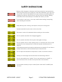
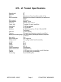
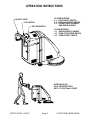
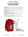
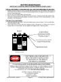
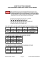
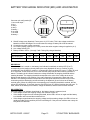
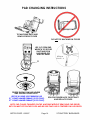
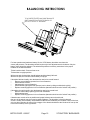
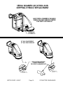
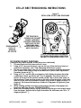
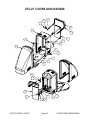
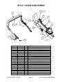
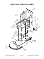
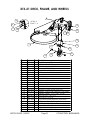
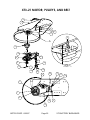
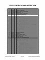
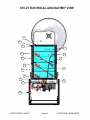
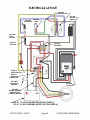
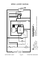
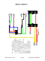
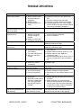
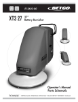
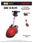
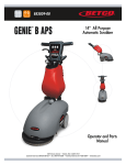
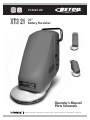
E12601-00 XT3 21 21 Battery Burnisher Operators Manual Parts Schematic ©2007 Betco Corporation. All Rights Reserved. 1001 Brown Avenue Toledo, Ohio 43607-0127 888-GO-BETCO www.betco.com TABLE OF CONTENTS COVER PAGE 1 LEFT BLANK INTENTIONALLY 2 TABLE OF CONTENTS 3 SAFETY INSTRUCTIONS 4-5 SPECIFICATIONS 6 PROCEDURES FOR LOADING, TRANSPORTING, AND UNLOADING 7 OPERATING INSTRUCTIONS 8 BATTERY CHARGING 9 BATTERY MAINTENANCE 10 BATTERY CHARGER OPERATION 11 CHARGER SETTINGS FOR DIFFERENT BATTERIES 12 BATTERY DISCHARGE INDICATOR AND HOUR METER INFORMATION 13 PAD CHANGING INSTRUCTIONS 14 BALANCING INSTRUCTIONS 15 SERIAL NUMBER LOCATION AND SHIPPING EYEBOLT REPLACEMENT 16 XT3-21 BELT TENSIONING INSTRUCTIONS 17 XT3-21 COVER AND HANDLE 18 - 19 XT3-21DECK, FRAME, AND WHEELS 20 - 21 XT3-21 MOTOR, PULLEYS, AND BELT 22 - 23 XT3-21 PAD DRIVER ASSEMBLY 24 XT3-21 ELECTRICAL AND BATTERY VIEW 25-27 ELECTRICAL LAYOUT 28 WIRING LADDER DIAGRAM 29 WIRING HARNESS 30 TROUBLE SHOOTING 31 WARRANTY 32 SAFETY INSTRUCTIONS Hazard Level Explanation or Description of Hazard Level Failure to follow safety instructions labeled injury or death to the machine operator or others. could result in severe could result in injury to the machine operator or others. Also, machine or property damage could occur. could result in damage Failure to follow safety instructions labeled to the machine or other property. This manual contains important information about your machine. Read and understand all instructions before operating the machine. Failure to read and follow the instructions could result in injury to the person operating the machine or injury to others. Damage to the machine or other property could occur if instructions are not followed. Do not operate this machine around any solvents, thinners, or other flammable liquids or materials. Electrical sparks can cause a fire or even an explosion. Do not smoke around the machine. Also, keep all sparks and flames away from the batteries. The batteries generate gases that can cause an explosion. Special care needs to be used when working on or near the batteries. Wear eye protection. Do not lay tools on batteries, as they may short out battery terminals. Do not wear metal jewelry, as it may short out battery terminals. Charging batteries can be dangerous. Be aware that the battery charger may have a relatively low voltage output, but the current output is very high and therefore dangerous. Do not operate the charger if any parts of the charger or charger cords are damaged. Do not stand on a wet floor when connecting or disconnecting charger to the power outlet or to the machine. Safety Instructions are continued on the next page BETCO CORP. 6/22/07 Page 4 XT3 BATTERY BURNISHER SAFETY INSTRUCTIONS Battery acid is dangerous. Wear eye and face protection, hand protection, and body protection when working on and around batteries. If you get acid on your skin, wash off immediately. If you get acid on your clothing, remove clothing and wash any skin that was in contact with the clothing. Baking soda mixed with water will help to neutralize the acid on your skin. The machine is very heavy, so be very careful when loading, transporting, and unloading the machine. Keep all body parts, clothing, and objects away from moving parts. Operate machine from the rear, not from the side. Disconnect a wire to the batteries before working on the machine. Do not operate machine with charger plugged in. Do not operate machine with any parts damaged or missing. Do not operate close to stairs, loading docks, or other drop-offs. Do not park machine in such a manner that it could roll, forward or backward, off a drop-off. Authorized personnel must perform maintenance and repairs. Do not alter or modify the machine, unless authorized by the manufacturer. Do not expose the electrical components to water or excessive moisture. Always put caution signs around the areas that are being cleaned. Do not use machine as a “ladder”. Do not use machine as a “forklift” to push stuff around. Do not ride or let anyone ride on the machine. Your machine warranty may be voided if parts other than PowerBuff parts are used. BETCO CORP. 6/22/07 Page 5 XT3 BATTERY BURNISHER XT3 - 21 Product Specifications Burnish path: Pad size: Motor: Motor controller: 21” 21” Maintenance Free, brushless, rated at 5 hp. Monitors and maintains consistent pad speed and torque Motor speed: 2000 rpm Pad pressure: Approx. 25 lbs. Pad driver: Flexible, Flex Lock III Center lock: Threaded, for easy installation Noise level: 70 dB (at operator) Voltage: 36 volt system Batteries: (3) Maintenance free, 12 volt, 140 ah, AGM Technology Run time: Up to 2.5 hours Charger: Onboard, high frequency computer controlled Battery/hour meter gauge: Yes, BDI (battery discharge indicator) computer controlled Key switch: Yes. Main power light: Yes, bright red Safety switch: Yes, spring loaded handle assembly Length: 56” Width: 24.5” Height: 40.5” Weight: 484 lbs. Tank Construction: Polyethylene Deck Construction: Cast Aluminum Wheels: (2) 6” heavy duty, non-marking, sealed bearings Casters: (2) 3” heavy duty, non-marking Productivity: Up to 24,000 sq.ft/hr. BETCO CORP. 6/22/07 Page 6 XT3 BATTERY BURNISHER Procedures for Loading, Transporting, and Unloading Battery Burnisher The machine is very heavy, so be very careful when loading, transporting, and unloading the machine. Use at least two people to load or unload the machine. • Loading Procedure Using a Ramp o It is not recommended that the battery burnisher be loaded using a ramp with an incline of more than 7 degrees. The machine is not self-propelled and therefore it is not able to assist itself up a ramp. It is too heavy to manually push up a steep incline. o If you must load with a ramp, the incline must be no more than 7 degrees. (This would permit a height of no more than one foot for an 8-foot ramp). o Ramp must be secured to vehicle, and be clean and dry. o Machine must be pushed or pulled straight up the ramp and never at an angle. • Loading Procedure Using a Lift Gate o Lift gate must have ample capacity to lift the burnisher. o Wheels must be firmly chocked to prevent burnisher from rolling off the lift gate. • Securing Battery Burnisher o Burnisher must be secured, so that it will not roll or turn over. Use chocks and tie downs to secure. o Please be aware that the battery burnisher is very heavy, and that a metal bulkhead in a van may not contain equipment in the event of an accident. The equipment in a van can be more dangerous than the accident itself. • Unloading Procedure Using a Ramp o Ramp must be long enough so that removal can be controlled. Use same ramp incline restrictions as used for loading burnisher. o Ramp must be secured to vehicle, and be clean and dry. o Machine must be taken straight down the ramp and never at an angle. o Do not let machine run over you or anyone else as it comes off ramp. BETCO CORP. 6/22/07 Page 7 XT3 BATTERY BURNISHER OPERATING INSTRUCTIONS SAFETY LEVER KEY SWITCH ROCKER SWITCH TO START BUFFING: # 1 - TURN ON KEY SWITCH # 2 - TURN ON ROCKER SWITCH # 3 - DEPRESS SAFETY HANDLE AND BEGIN BUFFING TO END BUFFING: # 1 - RELEASE SAFETY HANDLE # 2 - TURN OFF ROCKER SWITCH # 3 - TURN OFF KEY SWITCH AFTER EACH USE: PLUG CHARGER CORD INTO 110 VOLT WALL OUTLET BETCO CORP. 6/22/07 Page 8 XT3 BATTERY BURNISHER BATTERY CHARGING REFER TO NEXT THREE PAGES FOR BATTERY CHARGER OPERATION AND BATTERY MAINTENANCE • • • • • • • • • • • Become familiar with and follow the instructions issued by the charger manufacturer. Batteries should be charged after each period of use. Lead acid batteries do not develop a memory and need not be fully discharged before recharging. The charger is factory set to properly charger the size and type batteries that were supplied with your machine. Charge only in well-ventilated area. Keep sparks or flames away from a charging battery. Do not get the charger wet. Do not remove battery caps, the caps are vented. Caps on standard wet cell batteries. No caps on AGM batteries. Do not charge machine in a wet area. Do not stand in a wet area when plugging in charger to the 110 volt receptacle. Plug in the charger to a properly grounded 110 volt receptacle. Lights will indicate the charging status. Charger will shut off automatically when batteries are fully charged. TO CHARGE BATTERIES: • OPEN DOOR • REMOVE ELECTRICAL CORD • PLUG INTO 11O VOLT OUTLET • BATTERIES WILL BEGIN CHARGING BETCO CORP. 6/22/07 Page 9 XT3 BATTERY BURNISHER figure 2 WATER LEVEL IN THIS CELL IS TOO HIGH WATER LEVEL IN THIS CELL IS TOO LOW DO NOT OVERFILL. DO NOT FILL ABOVE THE BOTTOM OF THE TUBE THAT EXTENDS INTO BATTERY. KEEP ABOUT 1/4" BELOW BOTTOM OF TUBE. ADD DISTILLED WATER, AS NEEDED, SO THAT ELECTROLYTE LEVEL IS ABOUT 1/2" ABOVE PLATES. WATER LEVEL IN THIS CELL IS GOOD KEEP ELECTROLYTE LEVEL ABOVE TOP OF PLATES. CHECK ELECTROLYTE LEVEL IN ALL CELLS BETCO CORP. 6/22/07 Page 10 XT3 BATTERY BURNISHER BATTERY CHARGER OPERATION OPERATION • • • PLUG THE CORD FROM THE CHARGER INTO A 110 VOLT OUTLET • Batteries should now start charging. A test is run on the battery voltage to decide if the charging process should be started or not. If the battery is not connected to the battery charger, the display will show the word “bat”. The word will stay on, even if the test is failed (for instance, reversed polarities or incorrect battery connection). If the test is passed, the display will show the battery voltage for approximately 5 seconds and the battery will begin to be charged. The charging cycle progress will be shown by red, yellow, and green LED indicators. At the end of the charge, when the green indicator is on, unplug the cord from the socket and operate the machine. NOTE: THE MACHINE WILL NOT POWER ON IF THE CHARGER IS STILL PLUGGED IN TO THE 110 VOLT OUTLET. INDICATOR LIGHTS • Red indicator shows that the charging cycle has started. • Yellow indicator shows that the final phase of the charging cycle has started. • Green indicator shows that the charging cycle has finished. DISPLAY Press button “S” (for Selection) to display: • A = the charging current, • U = the battery voltage, • h = the charging time, • C = the charging ampere-hours [Ah], • E = the energy used [KWh]. CAUTION - CHARGER SETTINGS MUST BE CHANGED IF BATTERY TYPE IS CHANGED (SEE NEXT PAGE FOR SETTINGS) THIS BATTERY CHARGER IS FACTORY SET FOR THE TYPE OF BATTERIES THAT CAME WITH YOUR MACHINE. IF YOU SWITCH BATTERY TYPES (FOR EXAMPLE GO FROM AGM TYPE BATTERIES TO STANDARD WET CELL BATTERIES), THEN THE BATTERY CHARGER MUST BE REPROGRAMMED. SEE NEXT PAGE “HOW TO SET THE CHARGER FOR DIFFERENT SIZES AND TYPES OF BATTERIES” FOR INSTRUCTION. GENERAL INFORMATION AND WARNINGS • READ SAFETY INSTRUCTIONS ON PAGES 4 AND 5 • This is a state-of-the-art electronic high frequency automatic battery charger with microprocessor. • It is suitable for any battery type, if the charger has the proper settings. (Call manufacturer of machine on how to set the charger for different batteries than were supplied with your machine).. • Never disconnect the battery while charging, since this could cause sparks. • Never use the equipment in the rain, in areas used for washing, or in wet or damp areas. • Use battery chargers only in well ventilated areas. FOR LEAD ACID BATTERIES: • Control the water level after each charging process. (See “Battery Maintenance” page). • Refill with distilled water only. • Caution! The gases generated during charging are explosive. Do not smoke in the vicinity of the batteries. When working with cables and electrical equipment, avoid open flames and sparks. • Attention: Use protective glasses and gloves during battery maintenance. Battery acid causes injuries. In case of contact with battery acid, wash the affected parts with a lot of fresh water and consult a doctor if necessary. BETCO CORP. 6/22/07 Page 11 XT3 BATTERY BURNISHER HOW TO SET THE CHARGER FOR DIFFERENT SIZES AND TYPES OF BATTERIES THE INFORMATION THAT FOLLOWS IS PROVIDED SHOULD YOU EVER CHANGE THE TYPE OR SIZE OF BATTERIES IN YOUR MACHINE. CONSULT WITH THE EQUIPMENT MANUFACTURER BEFORE YOU MAKE ANY CHANGES TO THE CHARGER SETTINGS. DAMAGE COULD OCCUR TO THE BATTERIES AND MORE SERIOUS, IF THE BATTERIES ARE CHARGED TO THE INCORRECT AMPERAGE OR VOLTAGE, THE BATTERIES COULD EXPLODE. UP IS ON DOWN IS OFF DIP SWITCHES ARE LOCATED UNDER LABEL DIP 1, DIP 2, DIP 3, AND DIP 4 ARE FOR SELECTING THE CHARGING CURVE DIP 1 DIP 2 DIP 3 DIP 4 CHARGING CURVE OFF ON ON ON WET BATTERIES OFF ON OFF ON AGM BATTERIES PLEASE CONSULT EQUIPMENT MANUFACTURER BEFORE CHANGING DIP 5 AND DIP 6 ARE CONTROL THE CHARGING CURRENT DIP 5 DIP 6 AMPERAGE ON ON 15 A OFF ON 20 A ON OFF 25 A OFF OFF 30 A DIP 7 AND DIP 8 CONTROL THE BATTERY CHARGING VOLTAGE DIP 7 DIP 8 VOLTAGE ON ON 12 V OFF ON 24 V ON OFF 36 V OFF OFF 48 V BETCO CORP. 6/22/07 Page 12 XT3 BATTERY BURNISHER BATTERY DISCHARGE INDICATOR (BDI) AND HOUR METER 7 0 1 2 6 5 4 3 Connector pin configuration (B) 1: hour meter input 2: key + 3: relay + 4: relay – 5: battery – 6: not used 7: not used 8: battery + A C 1 2 3 4 B 5 6 7 8 D E BACK FRONT A. Shutoff voltage rotary dipswitch. Factory set to 4 (32.76 volts). This is the voltage at which the batteries are 80% discharged. Do not set below this voltage or battery life will be shortened. B. Connections to meter (molex connector) C. Hour meter (display is always on, but only counts time when negative voltage is applied to pin 1) D. Low voltage shutoff LED E. Battery condition LED’s. (1 through 7 with 7 being fully charged batteries) POSITION 0 1 2 3 4 5 6 7 VOLTS PER CELL 1.63 1.68 1.73 1.76 1.82 1.84 1.86 1.89 TOTAL VOLTS 29.34 30.24 31.14 31.68 32.76 33.12 33.48 34.02 BDI DISPLAY When the machine is turned on, the battery level indicator is switched on and the LED (D or E) corresponding to the position currently held by the rotary dipswitch will turn on. Position 0 (zero) corresponds to the red LED (D), position 1 corresponds to the first yellow LED (row of 7 LED’s (D), and so on. After that, all the LED’s turn on for a few seconds (lamp test) and then ordinary operation is started. The battery level indicator features two voltage thresholds: the stopping threshold and the resetting threshold. The stopping threshold corresponds to the value of the voltage at the end of discharge and depends on the position of the rotary dipswitch (A) located at the back side of the indicator. The resetting threshold corresponds to the reset-point threshold of the device (this value varies along with the discharging current selected by the dipswitch (A) and is close to the battery nominal value). When the voltage value corresponding to the stopping threshold is reached, the last yellow LED will flash for 15 seconds, then the red LED will turn on, and the blocking relay will open. To reset, switch off the battery level indicator, charge the batteries, and then switch on the machine. BDI OPERATION When the battery level indicator is switched on, the battery voltage is measured, and: • If the voltage is below the stopping voltage, the machine will not run. • If the voltage is higher than the resetting threshold, all the LED’s will turn on again and the battery level indicator will reset and the machine will run. • If the voltage ranges between the stopping voltage and the resetting voltage, the LED’s will turn on rapidly according to the condition prior to the switching off. If the previous condition was a stop, the last yellow LED will flash. BETCO CORP. 6/22/07 Page 13 XT3 BATTERY BURNISHER PAD CHANGING INSTRUCTIONS TILT MACHINE BACK AND REMOVE FRONT COVER DO NOT TILT MACHINE ON ITS SIDE USE 3/4" OPEN END WRENCH TO SECURE SHAFT AND SPIN PAD DRIVER OFF SHAFT BY HAND DETAIL A SCALE 1 : 6 A CENTER THE PAD ON PAD HOLDER AND TIGHTEN CENTER LOCK USE THE HI-SHINE LIGHT BURNISH PAD 21" IS PART NUMBER F084621 (5 PER CASE) 27" IS PART NUMBER F084627 (5 PER CASE) SPIN PAD DRIVER BACK ONTO SHAFT AND REPLACE COVER NOTE: PAD CAN BE CHANGED ON THE MACHINE WITHOUT REMOVING PAD DRIVER, BUT YOU MUST GET ON THE FLOOR AND BE SURE THAT PAD IS CENTERED ON PAD DRIVER. BETCO CORP. 6/22/07 Page 14 XT3 BATTERY BURNISHER BALANCING INSTRUCTIONS TO ACHIEVE PROPER MACHINE BALANCE SHIFT SHIMS FROM FRONT TO BACK OR BACK TO FRONT OF BATTERIES For best operation and maximum battery life, the XTG3 battery burnisher must have the correct pad pressure. The burnisher should require only minor adjustments to the balance. Only the battery shims should be adjusted. The wheel axel positions are factory set and are in the proper locations in the wheel brackets. Tilt the burnisher back. Remove front cover. Tilt burnisher to upright position. With a new pad, the burnisher should hesitate and then barely fall back. With a worn pad, the burnisher should barely sit upright. If burnisher falls back easily, then the batteries need to be moved forward. • Remove several battery spacers from front of batteries • Slide batteries forward • Add spacer(s) to rear of batteries • Slide batteries tight against rear spacers (can be done by tilting machine back quickly) • Replace remaining spacers in front of batteries (batteries should now be “locked” into position) If burnisher sits upright easily, then the batteries need to be moved back. • Remove some battery spacer(s) from rear of batteries • Slide batteries back • Replace remaining spacers in front of batteries (batteries should now be “locked” into position) If batteries are moved as far as possible and proper balance cannot be achieved, then one of the wheels may be moved to achieve balance. The burnisher is factory balanced, so this is usually not necessary unless different batteries are installed by the customer. Most of the time, only one wheel needs to be moved. Any stagger of the wheels should have the left wheel in front (to the front of the machine) of the right wheel. BETCO CORP. 6/22/07 Page 15 XT3 BATTERY BURNISHER SERIAL NUMBER LOCATION AND SHIPPING EYEBOLT REPLACEMENT HAVE SERIAL NUMBER AVAILABLE WHEN CALLING SERVICE CENTER FOR PARTS OR SERVICE LOCATION OF SERIAL # 21" HAS ONE EYEBOLT 27" HAS TWO EYEBOLTS A REPLACE THE SHIPPING EYEBOLT WITH THE PROVIDED HAMMER RIVET DETAIL B SCALE 1 : 4 DETAIL A SCALE 1 : 4 BETCO CORP. 6/22/07 B Page 16 XT3 BATTERY BURNISHER XT3-21 BELT TENSIONING INSTRUCTIONS figure 2 DETAIL VIEW OF BELT AND TENSIONER fig. 1 TENSIONER BOLT USE 9/16" WRENCH OR SOCKET TEST TENSION BY PUSHING OR PULLING ON BELT. WITH BELT PROPERLY TENSIONED, THE PULLEY ON THE TENSIONER ARM SHOULD MOVE ONLY ABOUT AN INCH. USE 15/16 SOCKET WITH EXTENSION TO TIGHTEN TENSIONER IN DIRECTION SHOWN TO PUSH INSIDE OF BELT OUT TO TIGHTEN THE BELT TENSIONER (Tensioner may have slipped, or belt may have stretched) 1. Tilt machine back and remove front cover 2. Using a 3/4" open end wrench, secure the top of the shaft and remove pad driver assembly. (see "Pad Changing Instructions" page) 3. On the top of the deck, use a 9/16” wrench or socket to loosen tensioner bolt. Leave a little snug to help hold tensioner in place after adjustment. (location shown in fig. 1) 4. Using a 15/16” socket with an extension, fully tighten tensioner from the underside of deck, and back off 10 to 15 degrees. This will be about 2 inches at the end of the socket handle. (Note: This is about one mark on the tensioner. There are five marks on the side of the tensioner, which are difficult to see with the tensioner in place. Each mark is equal to about 15 degrees. This leaves the tensioner at about 60 degrees of tightness.)(see figure 2) 5. While holding position tensioner in this proper location, fully tighten the tensioner bolt from the top. TIGHTEN SECURELY! 6. Make sure tensioner did not slip by pushing or pulling on side of belt away from tensioner. Belt should be tight and move the tensioner arm 10 to 15 degrees (about 1 "). BETCO CORP. 6/22/07 Page 17 XT3 BATTERY BURNISHER XT3-21 COVER AND HANDLE 16 15 14 13 3 11 2 16 8 14 3 5 6 7 1 5 4 10 7 8 7 2 6 BETCO CORP. 6/22/07 5 4 9 Page 18 XT3 BATTERY BURNISHER XT3-21 COVER AND HANDLE 18 NUT IS HIDDEN 11 17 21 13 13 22 A 19 20 6 15 6 16 11 14 12 ITEM NO. 1 2 3 4 5 6 7 8 9 10 11 12 13 14 15 16 17 18 19 20 21 22 PART NO. E012653 E012633 E012625 E012633 E012676 E011834 E012219 E012632 E012640 E012641 E012638 E010259 E012639 E011051 E011504 E011136 E011122 E012242 E012215 E011565 E011553 E012221 BETCO CORP. 6/22/07 QTY. 1 3 1 3 12 11 8 1 1 1 1 2 1 4 4 4 1 1 1 1 1 1 DETAIL A SCALE 1 : 2 DESCRIPTION 21" DURACOAT MILLED DECK LATCH, RUBBER DRAW (PART 1 OF 2) ROTOMOLDED SHROUD XT21G3 LATCH, RUBBER DRAW (PART 2 OF 2) RIVET, LOAD SPREADING, 5/32" WASHER, FLAT, 1/4 SCREW, 1/4-20 x 1, PHMS, BLACK DOOR, ACCESS HINGE WELDMENT A HINGE WELDMENT B HANDLE, MAIN XTG3 CAP, TUBING, BLACK, 1" HANDLE, SAFETY SHUTOFF XTG3 BOLT, HEX, 1/4-20 x 1.25 WASHER, LOCK, 3/8 WASHER, FLAT, 3/8 SAE SCREW, 1/4-20 x .5, PHMS, SS NUT, FLANGED, 1/4-20 SWITCH, SAFETY SHUTOFF SPRING, HANDLE RETURN LANYARD 3/64 x 6" SLEEVE FOR LANYARD, ALUMINUM Page 19 XT3 BATTERY BURNISHER XT3-21 DECK, FRAME, AND WHEELS 7 4 7 11 13 6 8 5 9 8 11 9 13 14 3 8 9 1 24 2 BETCO CORP. 6/22/07 Page 20 XT3 BATTERY BURNISHER XT3-21 DECK, FRAME, AND WHEELS 22 DETAIL A SCALE 1 : 4 8 9 A 10 23 11 21 12 12 3 19 17 18 15 ITEM NO. 1 2 3 4 5 6 7 8 9 10 11 12 13 14 15 16 17 18 19 20 21 22 23 24 PART NO. E010705 E011531 E012653 E012634 E012643 E011833 E012204 E012248 E011133 E012242 E011424 E011432 E011136 E012635 E012672 * E012675 E011176 E012644 E012285 E012237 E012656 E012242 E012584 BETCO CORP. 6/22/07 20 16 QTY. DESCRIPTION 1 BUMPER GUARD, RED 5 RIVET, T-RIVET, BSP T63 1 21" DURACOAT MILLED DECK 1 FULL MOUNT FOR XT21 1 CHARGER CORD WRAP 2 SCREW, 1/4-20 x .75, PHMS, BLACK 2 TRIM, EDGE, SOLD BY THE FOOT 11 BOLT, HEX, 1/4-20 x 1 12 WASHER, FLAT, 1/4 10 NUT, FLANGED, 1/4-20 8 BOLT, HH, 3/8-16 x 1.5 8 NUT, FLANGE, 3/8-16 8 WASHER, FLAT, 3/8 SAE 2 HANDLE TO BASE MOUNT FOR XT21 4 BEARING, SEALED BALL BEARING FOR WHEEL 2 BUSHING, WHEEL, 1.5 x .5 OD x .312 ID 2 BOLT, HH, 5/16 - 18 x 2.75 2 NUT, NYLOC, 5/16-18 2 ADJUSTABLE WHEEL BRACKET 4.062 AXLE 2 WHEEL, 6" x 1.5" WITH BUSHING 2 CASTER, 3" WITH GREY WHEEL 1 CHAIN, STAINLESS, STATIC, SOLD BY THE FOOT 1 NUT, NYLOCK, 1/4-20 1 RIVET, 3/8" HAMMER RIVET Page 21 XT3 BATTERY BURNISHER XT3-21 MOTOR, PULLEYS, AND BELT 16 1 12 13 17 2 A 3 14 19 8 15 9 10 18 DETAIL A SCALE 1 : 2 7 10 20 10 20 14 17 13 12 8 7 9 18 19 15 BETCO CORP. 6/22/07 Page 22 XT3 BATTERY BURNISHER XT3-21 MOTOR, PULLEYS, AND BELT 16 5 4 6 3 11 12 13 1 ITEM NO. 1 2 3 4 5 6 7 8 9 10 11 12 13 14 15 16 17 18 19 20 PART NO. QTY. DESCRIPTION E012653 1 21" DURACOAT MILLED DECK * 4 SHIM FOR FRONT END BEARING HOUSING E012284 1 BEARING AND SHAFT ASSEMBLY E010116 4 BOLT, 7/16-14 x 1.25 E012218 4 WASHER, FLAT, 7/16 SAE E012217 4 WASHER, LOCK, 7/16 E012459 1 KEYSTOCK, 7mm x 8mm x 30mm E012401 1 PULLEY, 7.5 OD, QT STYLE E012400 1 PULLEY BUSHING, 25MM SHAFT, QT STYLE E012248 4 BOLT, HEX, 1/4-20 x 1 E011051 1 BOLT, HEX, 1/4-20 x 1.25 E011136 5 WASHER, FLAT, 3/8 SAE E011504 5 WASHER, LOCK, 3/8 E010459 1 BELT TENSIONER, SMALL FOR XT E010107 1 BELT, BX40 E012197 1 MOTOR,36 VDC, BRUSHLESS E011424 4 BOLT, HH, 3/8-16 x 1.5 E012663 1 PULLEY BUSHING, 1" SHAFT, QT STYLE E012662 1 PULLEY, BK45QT E011723 1 KEYSTOCK, 1/4 x 1/4 BETCO CORP. 6/22/07 Page 23 XT3 BATTERY BURNISHER XT3-21 FLEX-LOC PAD DRIVER ASSEMBLY (COMPLETE ASSEMBLY- PE50028) 5 6 2 1 7 3 8 4 ITEM NO. 1 2 3 4 5 6 7 8 PART NO. QTY. DESCRIPTION E010250 1 FLEX-LOC 21 E010586 1 SHAFT TO PAD DRIVER COUPLING E012517 1 CENTER-LOC 2 (COMES AS A SET 1 OF 2) E012517 1 CENTER-LOC 2 (COMES AS A SET 2 OF 2) E012247 6 BOLT, HEX, 5/16-18 x 1.25 E011505 6 WASHER, LOCK, 5/16 E011176 6 NUT, NYLOC, 5/16-18 E010118 3 RIVET, AAP64 BETCO CORP. 6/22/07 Page 24 XT3 BATTERY BURNISHER XT3-21 ELECTRICAL AND BATTERY VIEW 72 70 83 69 95 71 73 68 60 67 61 62 94 62 76 93 75 WIRING HARNESS (CONTROLLER TO MOTOR AND ELECTRICAL PARTS) 86 29 59 29 6 5 28 90 29 66 91 89 63 64 BETCO CORP. 6/22/07 55 Page 25 XT3 BATTERY BURNISHER XT3-21 ELECTRICAL AND BATTERY VIEW ITEM NO. 5 6 28 29 55 59 60 61 62 63 64 65 66 67 68 69 70 71 72 73 74 75 76 77 78 79 80 81 82 83 84 85 86 87 88 89 90 91 92 93 94 95 96 PART NO. QTY. DESCRIPTION E012643 1 CHARGER CORD WRAP E011833 2 SCREW, 1/4-20 x .75, PHMS, BLACK E011834 16 WASHER, FLAT, 1/4 E012219 17 SCREW, 1/4-20 x 1, PHMS, BLACK E012197 1 MOTOR,36 VDC, BRUSHLESS E012628 1 CHARGER, ON-BOARD, SPE WITH CORDS E012219 6 SCREW, 10-24 x 1, PHMS, BLACK E011834 6 WASHER, #10, SAE, BLACK E010137 2 TUBE CLIP, .5, COV-0909 E010878 1 ELECTRICAL PLUG, SB-175, GREY, 36 VOLT E011623 2 BOLT, HH, 1/4-20 x 1.25 E012592 1 SOLENOID, 36V, CURTIS-ALRIGHT E011353 1 TUBE CLIP, .75 COV-1309 E011106 1 FUSE, 10 AMP, AGC, 1.25" LONG E011835 1 FUSE HOLDER, FOR 1.25" AGC FUSE E012630 1 BDI (BATTERY DISCHARGE INDICATOR AND HOUR METER) E012646 1 LAMP, LED, 36V E011529 1 SWITCH, ROCKER, DPST E012629 1 KEYSWITCH, HEAVY DUTY WITH 2 KEYS E011528 1 CIRCUIT BREAKER, 70 AMP E010708 1 CABLE TIE, BLACK, 7.5" * 1 SPARE KEY E012199 1 MOTOR CONTROLLER E012631 1 HEAT SINK E012561 6 CABLE TIE, BLACK, AF529 E012660 14 SHIM, PLASTIC, 12 x 1.5 x .125 E012642 1 BATTERY TRAY STEEL E012652 3 BATTERY, AGM, MAINTENANCE FREE E012624 1 BATTERY TRAY, PLASTIC, 3 BATTERIES E010133 1 WIRE, BATTERY CABLE, RED, 4 GA x 11" E012568 1 WIRE, BATTERY CABLE, 4GA x 7.75" E012673 1 LOOM, 1" DIA E012655 1 WIRING HARNESS FOR XT3 E012543 3 TERMINAL PROTECTOR, STRAIGHT, RED E012542 3 TERMINAL PROTECTOR, STRAIGHT, BLACK E012562 1 WIRE, BATTERY CABLE, 4 GA, BLACK, 36" E012563 1 WIRE, BATTERY CABLE, 4 GA, RED, 36" E012669 1 WIRE, BATTERY CABLE, 4 GA, RED WITH YELLOW ENDS, 33" E011139 2 WIRE, BATTERY CABLE, 4 GA, BLACK OR RED, 16" E012565 1 WIRE, BATTERY CABLE, 4 GA, BLACK, CHARGING, 24" E012564 1 WIRE, BATTERY CABLE, 4 GA, RED, CHARGING, 28" E012562 1 WIRE, BATTERY CABLE, 4GA, BLACK, 36" E011837 1 WIRE, BATTERY CABLE, 4 GA, RED, 7" BETCO CORP. 6/22/07 Page 26 XT3 BATTERY BURNISHER XT3-21 ELECTRICAL AND BATTERY VIEW 79 80 82 81 87 88 92 78 78 95 92 84 79 83 77 39 BETCO CORP. 6/22/07 Page 27 XT3 BATTERY BURNISHER ELECTRICAL LAYOUT E012630 BDI (REAR OF BDI) E011529 ROCKER SWITCH E012629 E012646 KEYSWITCH LAMP E011835 FUSE HOLDER E011106 FUSE 10A E012592 SOLENOID E012215 SAFETY SWITCH E012199 MOTOR CONTROLLER E011528 70A CIRCUIT BREAKER E012628 CHARGER E012655 WIRING HARNESS (INCLUDES ALL CONTROL WIRING) E012197 MOTOR XT3-21, 12 VOLT AGM BATTERY E012652 (NEED 3) XT3-27, 6 VOLT STANDARD BATTERY E011563 (NEED 6) BETCO CORP. 6/22/07 Page 28 XT3 BATTERY BURNISHER CB BETCO CORP. 6/22/07 - + Page 29 LED R c KEY K - KEY SWITCH R - ROCKER SWITCH S - SAFETY RUN SWITCH CB - CIRCUIT BREAKER F - FUSE - + K F W U B+ B- 12 RED BLACK BLUE GREEN WHITE S 1 2 3 4 5 BDI 8 ALSO SEE OTHER PAGES FOR: - ELECTRICAL AND BATTERY VIEW - ELECTRICAL LAYOUT - WIRING HARNESS - BATTERY DISCHARGE AND HOUR METER INFORMATION 1 M2 M3 M1 20 19 MOTOR 18 3 CONTROL 17 8 V MOTOR AC WIRING LADDER DIAGRAM CHARGER XT3 BATTERY BURNISHER BETCO CORP. 6/22/07 Page 30 6 F 7 M NOTE - MOLEX CONNECTORS VIEWED FROM WIRE SIDE 1 - MOLEX 39-01-2200 TO CONTROL 2 - MOLEX 39-01-2201 FROM MOTOR 3 - MOLEX 39-01-2080 TO METER F - FEMALE INSULATED TERMINAL M - MALE INSULATED TERMINAL BC - INSULATED BUTT CONNECTOR RED 5 - SOLENOID COIL SIDE A RED 6 - SOLENOID COIL SIDE B YELLOW 7 - TO SAFETY RUN SWITCH BLUE 8 - TO KEY SWITCH GREEN 9 - TO LAMP POS GREEN 10 - TO LAMP NEG BROWN 11 - TO CHARGER INHIBIT BROWN 12 - TO ROCKER SWITCH BLACK 13 - CONTROLLER NEG 1 2 3 4 5 6 7 8 5 F 3 F 12 1 3 1 12 20 19 8 18 17 BC BC 2 12 20 19 18 17 F 10 13 M 7 M 11 F 8 M 9 WIRING HARNESS XT3 BATTERY BURNISHER TROUBLE-SHOOTING PROBLEM CAUSE POSSIBLE SOLUTION No sign of power. No on lamp, no BDI readout. (a) Bad connection (b) Bad connection to BDI (c) On-board charger is plugged in (d) Batteries dead (e) Charger plugged into outlet Powers on with key switch, but solenoid does not “click” with rocker switch. Powers on, solenoid “clicks”, but does not run Bad connection Pad “bogs down” Machine will not set upright with cover on Low runtime Machine vibrates Noise coming from underside of deck Machine hard to push (a) Safety run switch problem. Not pulling plunger enough to activate. (b) Safety run switch wire connectors may be loose Too much pad pressure Too little pad pressure (a) Improper charge (b) Old batteries or defective cell in battery (c) Too much pad pressure. (d) BDI set to too high a voltage (a) Pad not centered (b) Pad is torn or worn excessively Belt is loose and causing belt tensioner to “chatter”. (a) Worn pad (b) Worn wheel bearings (c) Pad out of alignment Machine pulls left (a) Worn pad (b) Wrong pad (c) Right side of pad needs a little more contact than the left so “pad assist” can help pull machine forward . Uneven floor buffing (right side of pad polishes and left side does not) Right side of pad contacting too much, therefore left side is not contacting enough. BETCO CORP. 6/22/07 Page 31 (a) Check all connections. (b) Make sure connector is fully pushed into BDI. (c) Disconnect charger from wall outlet. (d) Recharge or replace batteries as needed. (e) Unplug charger from 110v outlet. Charger has an “inhibit” circuit that prevents machine from running if charger is plugged in. Check all connections. (a) Cable may have slipped and sleeve needs to be re-crimped or replaced. (b) Push in connectors Decrease pressure using directions on “Balancing Instructions” page Increase pad pressure using directions on “Balancing Instructions” page (a) Make sure that batteries get a full charge after each use. (b) Replace batteries. Best to replace as a set. (c) Balance machine. See “Balancing Instructions” page. (d) See BDI instruction page on how to set to a value of 4 for optimal run time and battery life (a) Remove pad and re-center the pad (b) Replace pad Tighten belt. See page with “Belt tightening instructions”. (a) Replace pad. (b) Replace bearings or replace wheels. (c) See solution to next problem “Machine pulls left”. (a) Replace pad (b) Replace pad with pad approved use with XT burnisher. (c) Add a small shim (.010 thick) between bearing housing and deck on the right side. This will “push” right side down toward floor. (If there are too many shims, then left side of pad will not contact properly). The reverse of the previous procedure. Remove one of the small shims (.010 thick) between bearing housing and deck on the right side XT3 BATTERY BURNISHER Betco Warranty Express Program™ Revised November 1, 2006 10 Year Coverage Subject to the conditions stated below, Betco Corporation warrants parts and labor on rotationally molded polyethylene tanks/housings and injection molded vacuum head assemblies to be free from defects in materials and workmanship for a period of ten years to the original purchaser. 3 Year Coverage Subject to the conditions stated below, Betco Corporation warrants parts and labor on all other Betco components to be free from defects in materials and workmanship for a period of three years to the original purchaser. 1 Year Coverage Subject to the conditions stated below, Betco Corporation offers a limited warranty on parts and labor on the following equipment, parts and accessories to be free from defects in material and workmanship for a period of one year to the original purchaser. ●DM Series Vacuums: #85506-00, #85507-00 ●Bac Pac Lite Vacuum: #85903-00 ●FiberPRO® Floor Dryer: #85507-00 ●WORKMAN™ Series Vacuums: #85024-00, #85025-00, #85026-00, #85027-00 ●CV100T Vacuum: #85023-00 ●All Tools and Accessories ●All Battery Chargers ●All Batteries are pro-rated for 1 year. Allowable Travel Time Warranty Reimbursement: Eligible equipment: All battery and propane powered equipment products. Warranty period: 90 days from date of sale to the original purchaser. A maximum 60 mile round trip at 44 cents per mile will be allowed for warranty consideration. Propane Machine Warranty: Honda engines are warranted by Honda for a period of 2 years against manufacturer defect. Kawasaki engines are warranted by Kawasaki for a period of 2 years against manufacturer defect. All other components (except wear items)* are warranted by Betco Corporation for a period of 3 years. *Wear items exempt from warranty consideration include but may not be limited to: power cords, transport wheels, vacuum bags, belts, squeegee blades, pad drivers, clutch plates, handle grips, filters, screens, throttle cables, brushes and carbon brushes. Subject to the conditions and exceptions stated in this warranty, Betco warrants the Betco products to be free from defects in material and workmanship, under normal use and service, for the periods listed under the warranty policy to the original purchaser. At any time during the warranty period, Betco will furnish replacement parts for the Betco products to the original purchaser. Such parts will be furnished and charged including transportation costs, to the original owner through any Betco authorized Service Distributor. If the original part is returned within the warranty policy period from date of delivery for inspection by Betco and is found to be defective, the owner will be credited for the cost of replacement parts plus shipping and handling. Replacement parts that have become defective through wear or abuse are not included in this warranty. This warranty does not apply to damage or defect caused by accident, misuse, negligence, fire or to any Betco product which has been serviced or repaired by other than an authorized Betco Service Distributor or Betco factory personnel. This warranty is void if products are used for any purpose other than that which was intended. There are no other warranties expressed or implied. In no event shall Betco be liable for incidental or consequential damages or any damage to person or property. (Please note some states do not allow the exclusion or limitations for incidental and consequential damages.) ©2006 Betco Corporation All Rights Reserved. 1001 Brown Avenue Toledo, Ohio 43607-0127 888-462-3826 www.betco.com