1
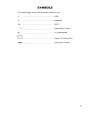
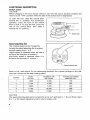
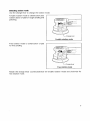
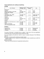
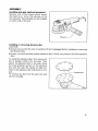
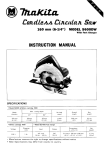
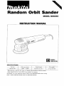
Random Orbit Sander
MODEL BO6040
INSTRUCTION MANUAL
DOUBLE
INSULATION
Pad size
Orbits p e r minute
Overall length
Net w e i g h t
150 mm 16”)
1,600 - 5,800
316 mm (12-1/2”)
2.7 kg (5.9 Ibs)
GENERAL SAFETY RULES
USA0021
(For All Tools)
WARNING! Read and understand all instructions. Failure
t o follow all instructions listed below, may result in electric
shock, fire and/or serious personal injury.
SAVE THESE INSTRUCTIONS
Work Area
1. Keep your work area clean and well lit. Cluttered benches and dark areas invite
accidents.
2. Do not operate power tools in explosive atmospheres, such as in the presence
of flammable liquids, gases, or dust. Power tools create sparks which may
ignite the dust or fumes.
3. Keep bystanders, children, and visitors away while operating a power tool.
Distractions can cause you t o lose control.
Electrical Safety
4. Double Insulated tools are equipped w i t h a polarized plug (one blade is wider
than the other.) This plug will fit in a polarized outlet only one way. If the
plug does not fit fully in the outlet, reverse the plug. If it still does n o t fit,
contact a qualified electrician t o install a polarized outlet. Do n o t change
the plug in any way. Double insulation
eliminates the need for the three
wire grounded power cord and grounded power supply system.
5. Avoid body contact w i t h grounded surfaces such as pipes, radiators, ranges
and refrigerators. There is an increased risk of electric shock if your body is
grounded.
6. Do not expose power tools t o rain or w e t conditions. Water entering a power
tool will increase the risk of electric shock.
7. Do not abuse the cord. Never use the cord t o carry the tools or pull the plug
from an outlet. Keep cord away from heat, oil, sharp edges or moving parts.
Replace damaged cords immediately. Damaged cords increase the risk of
electric shock.
8. When operating a power tool outside, use an outdoor extension cord marked
“W-A’ or “W.“ These cords are rated for outdoor use and reduce the risk
of electric shock.
Personal Safety
9. Stay alert, watch what you are doing and use common sense when operating
a power tool. Do n o t use tool while tired or under the influence of drugs,
alcohol, or medication. A moment of inattention while operating power tools
may result in serious personal injury.
10. Dress properly. Do not wear loose clothing or jewelry. Contain long hair. Keep
your hair, clothing, and gloves away from moving parts. Loose clothes, jewelry
or long hair can be caught in moving parts.
2
11. Avoid accidental starting. Be sure s w i t c h is o f f before plugging in. Carrying
tools w i t h your finger on the switch or plugging in tools that have the switch
on invites accidents.
12. Remove adjusting keys or wrenches before turning the tool on. A wrench
or a key that is left attached t o a rotating part of the tool may result in personal
injury.
13. Do not overreach. Keep proper footing and balance at all times. Proper footing
and balance enables better control of the tool in unexpected situations.
14. Use safety equipment. Always wear eye protection. Dust mask, non-skid
safety shoes, hard hat, or hearing protection must be used for appropriate
conditions.
Tool Use and Care
15. Use clamps or other practical way t o secure and support the workpiece t o
a stable platform. Holding the work by hand or against your body is unstable
and may lead t o loss of control.
16. Do not force tool. Use the correct tool for your application. The correct tool
will do the job better and safer at the rate for which it is designed.
17. D o not use tool if switch does not turn it on or off. Any tool that cannot
be controlled with the switch is dangerous and must be repaired.
18. Disconnect the plug from the power source before making any adjustments,
changing accessories, or storing the tool. Such preventive safety measures
reduce the risk of starting the tool accidentally.
19. Store idle tools out of reach of children and other untrained persons. Tools
are dangerous in the hands of untrained users.
20. Maintain tools with care. Keep cutting tools sharp and clean. Properly
maintained tools, with sharp cutting edges are less likely to bind and are easier
t o control.
21. Check for misalignment or binding of moving parts, breakage of parts, and
any other condition that may affect the tools operation. If damaged, have
the tool serviced before using. Many accidents are caused by poorly
maintained tools.
22. Use only accessories that are recommended by the manufacturer for your
model. Accessories that may be suitable for one tool, may become hazardous
when used on another tool.
SERVICE
23. Tool service must be performed only by qualified repair personnel. Service
or maintenance performed by unqualified personnel could result in a risk of
injury.
24. When servicing a tool, use only identical replacement parts. Follow
instructions in the Maintenance section o f this manual. Use of unauthorized
parts or failure to follow Maintenance Instructions may create a risk of electric
shock or injury.
3
Specific Safety Rules
USBO40-2
1. Hold tool by insulated gripping surfaces when performing an operation where
the cutting tool may contact hidden wiring or its o w n cord. Contact with a
"live" wire will make exposed metal parts of the tool "live" and shock the
operator.
2. Hold the tool firmly.
3.Do not leave the tool running. Operate the tool only when hand-held.
4. This tool has n o t been waterproofed, so do not use water on the workpiece
surface.
5. Ventilate your work area adequately when you perform sanding operations.
SAVE THESE INSTRUCTIONS.
4
SYMBOLS
The followings show the symbols used for tool.
v
........................................................
volts
A
........................................................
amperes
Hz
........................................................
herts
?
, .......................................................
alternating current
b
........................................................
no load speed
.......................................................
Class II Construction
/min .......................................................
orbits per minute
5
FUNCTIONAL DESCRIPTION
Switch action
CAUTION:
Before plugging in the tool, always check to see that the switch actuates properly and
returns to the "OFF" position when the side of the switch lever is depressed.
To start the tool, slide the switch lever
toward the "I" position. For continuous
operation, press the front of the switch
lever to lock it. To stop the tool, press the
rear of the switch lever, then slide it
toward the "0"position.
Speed adjusting dial
The rotating speed can be changed by
turning the speed adjusting dial to a given
number setting from 1 to 5.
Higher speed is obtained when the dial is
turned in the direction of number 5.
And lower speed is obtained when it is
turned in the direction of number 1.
Speed adjusting dial
I
Number
per min.
Orbits
Oscillation rate
per minute
Forcible pad rotating
speed per min.
1
3,200
2
1,600
2,100
4,200
180
240
3
3,600
7,200
420
4
5
I
5,100
I
5,800
I
10,200
1 1,600
I
I
590
670
I
I
CAUTION:
The speed adjusting dial can be turned only as far as 5 and back to 1. Do not force it past
5 or 1, or the speed adjusting function may no longer work.
6
Selecting action mode
Use the change lever to change the rotation mode.
Forcible rotation mode is orbital action plus
rotation action of pad for rough sanding and
polishing.
I
Change lever
Forcible rotation mode
~~
Free rotation mode is orbital action of pad
for fine sanding
I
Change lever
Free rotation mode
Rotate the change lever counterclockwise for forcible rotation mode and clockwise for
free rotation mode.
7
Typical applications for sanding and polishing
Sanding
Use / Material
Paintwork:
Sanding
Repairs (scratches. rust stops)
Rough paint stripping
Rotation mode
Forcible / Free
Speed control
setting
Free
Forcible/ Free
Forcible
1-3
2-3
4-5
Soft
Hard
Soft
Pad
Plastics:
Soft plastics (PVC /ABS)
Hard Dlastics (FRP)
Woods:
Softwood
Hardwood
Veneers
Forcible / Free
Forcible
1-3
1-3
Super soft / Soft
/ Hard
Soft
___
Free
Forcible / Free
Free
1-3
3-5
1-2
Super soft / Soft
Soft
Super soft
Metals:
Non-ferrous metal (aluminum, copper)
Steel
Steel, rust removal
Hard metal (stainless steel)
Forcible / Free
Forcible
Forcible
Forcible
1-3
3-5
4-5
4-5
Soft
Soft / Hard
Super soft
Soft
Forcible
Forcible
Forcible
2-4
4-5
4-5
Sponge pad
Felt pad
Wool pad
Polishing
Applying wax
Removing wax
Polishing
The above information is intended only as a guide. In each case, the most appropriate
sanding disc grain should be determined by preliminary trials.
The tool equipped with electronic function is easy to operate because of the following
features.
Electronic speed control for obtaining constant speed
Possible to get fine finish, because the rotating speed is kept constantly even under the
loaded condition.
Soft start feature
Safety and soft start because of suppressed starting shock.
8
ASSEMBLY
Installing side grip (optional accessory)
Remove one of the screws which secure
the head cover. Screw the side grip on the
tool securely. The side grip can be installed
on either side of the tool.
Installing or removing abrasive disc
CAUTION:
Always be sure that the tool is switched off and unplugged before installing or removing
the abrasive disc.
Always use hook-and-loop system abrasive discs. Never use pressure-sensitive abrasive
discs.
To install the abrasive disc, first remove all
dirt or foreign matter from the pad. Then
attach the abrasive disc to the pad, using
the hook-and-loop system of the abrasive
disc and the pad. Be careful to align the
holes in the abrasive disc with those in the
pad.
To remove the disc from the pad, just pull
up from its edge.
DQ
i
Abrasive disc
9
Changing pad
Makita offers an extensive range of
optional super soft, soft and hard pads.
Remove the screw counterclockwise from
the center of the base with a hex wrench.
After changing the pad, tighten the screw
clockwise to secure the pad.
Dust collection (optional accessory)
If a Makita hose is used, you can connect the cuff to the nozzle directly. If other hose with
an inner diameter of 24 mm (15/16"), attach the joint between the nozzle and the cuff.
Cuff 7
Hose
10
7
OPERATION
Sanding operation
Turn the tool on and wait until it attains full
speed. Then gently place the tool on the
workpiece surface. Keep the pad flush with
the workpiece and apply slight pressure on
the tool.
CAUTION:
Never switch on the tool when it is in contact with the workpiece surface, causing an
injun/ to operator.
Never run the tool without the abrasive disc. You may seriously damage the pad.
Never force the tool. Excessive pressure may decrease the sanding efficiency, damage
the abrasive disc or shorten tool life.
Polishing operation
CAUTION:
*Use only a Makita genuine sponge pad, felt pad or wool pad (optional accessories).
*Always operate the tool at low speed to prevent work surfaces from heating abnormally.
*Never force the tool. Excessive pressure may decrease the polishing efficiency and cause
motor overload, resulting in tool malfunction.
Applying wax
Use an optional sponge pad. Apply wax to
the sponge pad or work surface. Run the
tool at low speed to smooth out wax.
NOTE:
*First, wax a not conspicuous portion of the work surface to make sure that the tool will
not scratch the surface or result in uneven waxing.
11
Removing wax
Use an optional felt pad. Run the tool at
low speed to remove wax.
Polishing
Use an optional wool pad. Run the tool at
low speed and apply the wool pad gently to
the work surface.
MAINTENANCE
CAUTlON:
Always be sure that the tool is switched off and unplugged before attempting to perform
inspection or maintenance.
To maintain products SAFETY and RELIABILITY, repairs, any other maintenance or adjustment should be performed by Makita Authorized or Factory Service Centers, always using
Makita replacement parts.
12
ACCESSORIES
CAUTION:
These accessories or attachments are recommended for use with your Makita tool specified in this
manual. The use of any other accessories or attachments might present a risk'of injury to persons.
The accessories or attachments should be used only in the proper and intended manner.
Hook-and-loop system abrasive disc
Hook-and-loop system sponge pad
(Hook & loop backing and pre-punchedholes)
Grit
Qty. per Pkg.
# 180
5
1
Grit
Qty per Pkg.
-
Hook-and-loop system wool pad
50
# 400
Sanding cloth 150
Hook-and-loop system felt pad
(For fine sanding)
Grit # 100, # 200, # 800
Pad 150
(Super soft, Soft, Hard)
*Joint
Side grip
Hex wrench
13
31
76
32
14
Random Orbit Sander Part Description
Item No. Descriotion
1
HEAD COVER
2
INDICATION LABEL
3
t FLAT HEAD SCREW M 8 X l l
4
TAPPING SCREW 4x30
5
GEAR HOUSING COMPLETE
6
0 RING 62
8
HEX. NUT M10
9
FLAT WASHER 10
10
UPPER BALANCE WEIGHT
11
SPIRAL BEVEL GEAR 42
12
BALL BEARING 6201LLB
13 PAN HEAD SCREW M4X16
14
CAP
15
PAN HEAD SCREW M4X12
16
KNOB COMPLETE
17
SPRING HOLDER
COMPRESSION SPRING 4
18
HOLDER
19
20
SKIRT COMPLETE
21
STOP RING (EXT) WR 55
22
BALL BEARING 681 lLLB
23
INTERNAL GEAR 29
24
SPINDLE
25
LOWER BALANCE WEIGHT
26
SLEEVE
27
BALL BEARING 6001DDW
28
BALL BEARING 6001 DDW
29
SPUR GEAR 26 COMPLETE
30
HEX SOCKET HEAD BOLT M8X14
31
BEARING R t l A l N E R 80 COMPLETE
RUBBER GUARD
32
33
PAD 150
34
RETAINING RING S-6
35
SPtRAL BEVEL GEAR 9
36
BALL BEARING 6001LLB
37
FLAT WASHER 12
38
GEAR HOUSING COVER
39
FAN 57
40
ARMATURE ASS'Y (with item 39.41-43)
Use Item N o
Qty
Descriotion
. .
1
41
I N S U L ~ ~ WASHER
I~N
1
2
4
1
1
1
1
1
1
1
42
43
44
45
46
47
48
49
50
51
4
52
1
1
1
1
1
53
54
55
56
57
58
59
60
61
FLAT WASHER 7
BALL BEARING 627DDW
LABYRINTH RUBBER RING 22
MAGNET SLEEVE
STOP RING E 4
BAFFLEPLATE
TAPPING SCREW 4x55
RETAINER
INSULATION COVER
FIELD
NAME PCATE
TAPPING SCREW 4x18
STRAIN RELIEF
TAPPING SCREW PT3X10
SWITCH BLOCK
BRUSH HOLDER
A.C. CARBON BRUSH CB-318
POWER SUPPLY CORD
CORD GUARD 8
SWITCH ST115A-40
COVER
INDICATION LABEL
REAR COVER
TAPPING SCREW 4x18
SWITCH KNOB
MAKITA LABEL
MOTOR HOUSING
BRUSHHOLDER
COMPRESSION SPRING 4
SWITCH LEVER
CONTROLLER
RETAINING RING 5-12
PAN HEAD SCREW M4X12
PAN HEAD SCREW M4X12
WAVE WASHER 6
1
1
1
1
1
1
1
1
1
1
1
1
1
1
1
1
1
1
1
1
1
1
62
63
64
65
66
67
68
70
71
72
73
74
75
76
77
ow. Used
1
1
1
1
1
1
2
2
2
1
1
2
1
4
1
1
1
1
1
1
1
1
1
1
1
1
1
1
1
1
1
1
3
3
1
15
WARNING
Some dust created by power sanding, sawing, grinding, drilling, and other
construction activities contains chemicals known [to the State of Califomia] to
cause cancer, birth defects or other reproductive harm. Some examples of
these chemicals are:
Lead from lead-based paints,
0 Crystalline silica from bricks and cement and other masonry products, and
Arsenic and chromium from chemically-treated lumber.
@
@
Your risk from these exposures vanes, depending on how often you do this
type of work. To reduce your exposure to these chemicals: work in a well
ventilated area, and work with approved safety equipment, such as those
dust masks that are specially designed to filter out microscopic particles.
i
MAKITA LIMITED ONE YEAR WARRANTY
Warranty Policy
Every Makita tool is thoroughly inspected and tested before leaving the factory. It is warranted t o
be free of defects from workmanship and materials for the period of ONE YEAR from the date of
original purchase. Should any trouble develop during this one-year period, return the COMPLETE
tool, freight prepaid, to one of Makita’s Factory or Authorized Service Centers. If inspection shows
the trouble is caused by defective workmanship or material, Makita will repair (or at our option,
replace) without charge.
This Warranty does not apply where:
repqrs have been made o r attempted by others:
repurs are required because of normal wear and tear:
The tool has been abused, misused or improperly maintained;
alterations have been made t o the tool.
IN NO EVENT SHALL MAKITA BE LIABLE FOR ANY INDIRECT, INCIDENTAL OR CONSEQUENTIAL DAMAGES FROM THE SALE OR USE O F THE PRODUCT. THIS DISCLAIMER
APPLIES BOTH DURING AND AFTER THE TERM O F THIS WARRANTY.
MAKITA DISCLAIMS LIABILITY FOR ANY IMPLIED WARRANTIES, INCLUDING IMPLIED
WARRANTIES O F “MERCHANTABILITY” AND “FITNESS FOR A SPECIFIC PURPOSE,”
AFTER THE ONE-YEAR TERM O F THIS WARRANTY.
This Warranty gives you specific legal rights, and you may also have other rights which vary from
state to state. Some states d o not allow the exclusion or limitation of incidental or consequential
damages, so the above limitation or exclusion may not apply to you. Some states d o not allow
limitation o n how long an implied warranty lasts, so the above Limitation may not apply to you.
Makita Corporation
3-11-8, Sumiyoshi-cho,
Anjo, Aichi 446-8502 Japan
884338-061
PRINTED IN JAPAN
2001-2-N