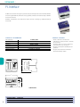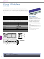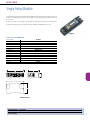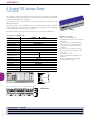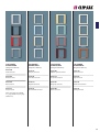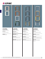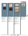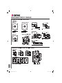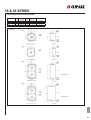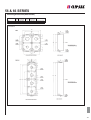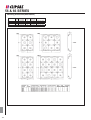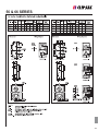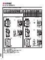
1
DEC
09
C-Bus technical selection guide
1
2
Contents
Page
n Introduction...................................................................................................................... 4
n Key Input Units................................................................................................................. 5
n Input Units....................................................................................................................... 21
n System Units.................................................................................................................... 38
n Output Units ................................................................................................................... 45
n Software Packages....................................................................................................... 65
3
Introduction
Clipsal, a brand of Schneider Electric, is dedicated to
supplying end-to-end building management and
integrated control with the products, solutions and
programs to help meet customers expectations.
Utilising the Schneider Electric product basket,
complete end-to-end solutions are possible with
products catering for any type or size of installation.
With solutions ranging from power and lighting
control, dimming, energy management, for home
automation and commercial applications.
The Clipsal C-Bus® system is a microprocessor
based wiring system to control lighting and other
electrical services.
Whether on/off control of a lighting circuit or
analogue type control such as dimming electronic
fluorescent ballasts, C-Bus can be used to control
and automate virtually any type of electrical load.
To ensure fast and reliable operation, each device
has its own inbuilt microprocessor, which can be
individually programmed via ‘point and click’ PC
based software, or via ‘learn mode’ which doesn’t
require a PC.
C-Bus information is held within individual units
rather than one central point. This ensures optimum
communication speed and reliability.
Whilst a computer is not necessary for normal
C-Bus operation, PC based control and
management software is available and provides
additional flexibility to clients requiring this type of
control. Clipsal C-Bus is suitable for a wide range of
applications, for example:
4
Commercial Lighting Control
• Fluorescent lighting control for energy cost saving
in high rise buildings
• High-bay control in warehouses for energy cost
saving
• Mood lighting in restaurants and retail outlets
• Flexible and integrated control of lighting and
audio visual equipment in board rooms
• Architectural lighting control for hotel foyers,
ballrooms, art galleries and museums
Standalone Room Lighting Control
• Integrated automation via touch screen user
interfaces for conference rooms and home
theatres
• Multiple scene / mood setting
Residential Automation
• Home entertainment - Integrated audio visual,
lighting control, and other electrical services
• Security - Integrated security, lighting and other
electrical services
• Comfort - Dimming and scene setting
• Convenience - Multiple point control, central point
control from touch screens, automated time based
control, automated ‘goodbye’ and ‘welcome home’
moods
Key Input Units
5
KEY INPUT UNITS |
Dynamic Labelling Technology, Saturn Series
Square
The square Saturn series dynamic labelling technology switches are learn enabled surface switches designed to control
lighting and other electrical services connected to a C-Bus network. The dynamic labelling technology allows the function
of the key to be programmed and displayed onto an LCD display next to the switch button.
The display found on the DLT switch, supports multi language text and user defined bitmaps, such as sliders and bar
graphs. The LCD display incorporates back lighting that can be enabled for night operation. In addition, the DLT switch
features a page scroll button that permits the user to navigate between pages, to access all control options.
Key input units are fully programmable and may be configured as toggle, dimmer, timer or scene control type functions.
With C-Bus switches it is possible to realise multi-way, multi-function switching or dimming control.
The Saturn DLT switches feature a glass fascia and are available in a range of colour backgrounds, including white, black,
mid brown and cream.
E5084DLGF
Key input units communicate with all other units and obtain power via a single twisted pair of connections to the C-Bus
unit. In the event of C-Bus power failure, non-volatile memory retains all programmed information relating to the unit’s
operating status.
TECHNIC AL INFORMATION
C-Bus Supply Voltage
Maximum Number of Units on
a Single C-Bus Network
Button Indicator
Timer Range
Timer Resolution
Dimmer Control
Number of Scenes
Standard Colours
Operating Temperature Range
Operating Humidity Range
15-36V DC @ 22mA
50
Programmable, Blue
1 sec to 18 hrs
1 sec
255 possible levels
8
White and Black
0˚C to 45˚C
10 - 95% RH
CATALOGUE NUMBER DESCRIPTION
Saturn Dynamic Labelling Technology
E5084DL
4 Gang Saturn DLT
Cover Selection: (GF) White, *(380) Cream, (680) Black, *(780) Mid-Brown
Saturn DLT Fascia
*5084DF
4 Gang Saturn DLT fascia
Cover Selection: *(GF) White, *(38) Cream, *(68) Black, *(78) Mid-Brown
6
*Ask for availability
PRODUC T FEATURES
• Available with 4 buttons
• Features blue light indicator with night light function
• Supports text labels and user defined bitmaps
• Ignore first press option
• Fallback to page 1 and 2 option
• Programmable using learn mode or via the C-Bus configuration software
• Programmed variables are stored in non-volatile memory
and are retained in case of loss of C-Bus power
• CE (European Community) compliant
KEY INPUT UNITS |
Dynamic Labelling Technology, Saturn Series
Rectangular
The rectangular Saturn series dynamic labelling technology switches are learn enabled surface switches designed to
control lighting and other electrical services connected to a C-Bus network. The dynamic labelling technology allows the
function of the key to be programmed and displayed onto an LCD display next to the switch button.
The display found on the DLT switch, supports multi language text and user defined bitmaps, such as sliders and bar
graphs. The LCD display incorporates back lighting that can be enabled for night operation. In addition, the DLT switch
features a page scroll button that permits the user to navigate between pages, to access all control options.
Key input units are fully programmable and may be configured as toggle, dimmer, timer or scene control type functions.
With C-Bus switches it is possible to realise multi-way, multi-function switching or dimming control.
The Saturn DLT switches feature a glass fascia and are available in a range of colour backgrounds, including white, black,
mid brown and cream.
Key input units communicate with all other units and obtain power via a single twisted pair of connections to the C-Bus
unit. In the event of C-Bus power failure, non-volatile memory retains all programmed information relating to the unit’s
operating status.
TECHNIC AL INFORMATION
C-Bus Supply Voltage
Maximum Number of Units on
a Single C-Bus Network
Button Indicator
Timer Range
Timer Resolution
Dimmer Control
Number of Scenes
Standard Colours
Operating Temperature Range
Operating Humidity Range
15-36V DC @ 22mA
50
Programmable, Blue
1 sec to 18 hrs
1 sec
255 possible levels
8
White and Black
0˚C to 45˚C
10 - 95% RH
5085DL680
PRODUC T FEATURES
• 5 buttons
• Features blue light indicator with night light function
• Supports text labels and user defined bitmaps
• Ignore first press option
• Fallback to page 1 option
• Programmable using learn mode or via the C-Bus configuration software
• Programmed variables are stored in non-volatile memory
and are retained in case of loss of C-Bus power
• CE (European Community) compliant
28
76
13
116
70
5085DL illustrated
42
CATALOGUE NUMBER DESCRIPTION
Saturn Dynamic Labelling Technology
5085DL
5 Gang Saturn DLT
Cover Selection: (GF) White, *(380) Cream, (680) Black, *(780) Mid-Brown
Saturn DLT Fascia
*5085DF
5 Gang Saturn DLT fascia
Cover Selection: *(GF) White, *(30) Cream, *(60) Black, *(70) Mid-Brown
*Ask for availability
7
KEY INPUT UNITS |
Saturn Input Switches
Square
The square Saturn series key input units are learn enabled surface switches designed to control lighting and other electrical
services connected to a C-Bus network.
Suitable for exclusive interiors, the Saturn series features an impact resistant glass fascia with white, mid brown, black or
cream backing. The round silver finish push buttons feature a dual coloured light indicator, providing a visual indication
of the switch state.
Key input units are fully programmable and may be configured as toggle, dimmer, timer or scene control type functions.
With C-Bus switches it is possible to realise multi-way, multi-function switching or dimming control.
Key input units communicate with all other units and obtain power via a single twisted pair connection to the C-Bus. In
the event of C-Bus power failure, non-volatile memory retains all programmed information relating to the unit’s operating
status.
TECHNIC AL INFORMATION
C-Bus Supply Voltage
Maximum Number of Units on
a Single C-Bus Network
Status Indicator
Timer Range
Timer Resolution
Dimmer Control
Mounting Centres
Standard Colours
Operating Temperature Range
Operating Humidity Range
15-36VDC @ 22mA
50
Programmable, Dual, Orange and Blue
1 sec to 18 hrs
1 sec
255 possible levels
84mm
White and Black
0˚C to 45˚C
0 - 95% RH, non-condensing
87
25
12
87
66
E5084NL illustrated
47
CATALOGUE NUMBER DESCRIPTION
Saturn Input Units
E5082NL
2 Gang Saturn input square
E5084NL
4 Gang Saturn input square
E5086NL
6 Gang Saturn input square
Cover Selection: (GF) White, *(380) Cream, (680) Black, *(780) Mid-Brown
8
*Ask for availability
E5084NLGF
PRODUC T FEATURES
• Available as 2, 4 or 6 key configuration
• Features bi-colour light indicator with night light
• Programmable using learn mode or via the C-Bus Toolkit
Software
• Programmed variables are stored in non-volatile memory
and are retained in case of loss of C-Bus power
• Features, 60.3mm mounting centres
• Available in glass finish with white, black, cream or
mid-brown background
• CE (European Community) compliant
KEY INPUT UNITS |
Saturn Input Switches
Rectangular
The rectangular Saturn series key input units are learn enabled surface switches designed to control lighting and other
electrical services connected to a C-Bus Network.
Suitable for exclusive interiors, the Saturn series features an impact resistant glass fascia with white, mid brown, black or
cream backing. The round silver finish push buttons feature a dual coloured light indicator, providing a visual indication
of the switch state.
Key input units are fully programmable and may be configured as toggle, dimmer, timer or scene control type functions.
With C-Bus switches it is possible to realise multi-way, multi-function switching or dimming control.
Key input units communicate with all other units and obtain power via a single twisted pair connection to the C-Bus. In
the event of C-Bus power failure, non-volatile memory retains all programmed information relating to the unit’s operating
status.
5084NLGF
TECHNIC AL INFORMATION
C-Bus Supply Voltage
Maximum Number of Units on
a Single C-Bus Network
Status Indicator
Timer Range
Timer Resolution
Dimmer Control
Mounting Centres
Standard Colours
Operating Temperature Range
Operating Humidity Range
15-36VDC @ 22mA
50
Programmable, Dual, Orange and Blue
1 sec to 18 hrs
1 sec
255 possible levels
84mm
White and Black
0˚C to 45˚C
0 - 95% RH, non-condensing
76
PRODUC T FEATURES
• Available as 2, 4 or 6 key configuration
• Features bi-colour light indicator with night light
• Programmable using learn mode or via the C-Bus Toolkit
Software
• Programmed variables are stored in non-volatile memory
and are retained in case of loss of C-Bus power
• Features, 84mm mounting centres, compatible with Clipsal
Mounting Boxes
• Available in glass finish with white, black, cream or
mid-brown background
• CE (European Community) compliant
25
12
116
66
5084NL
47
CATALOGUE NUMBER DESCRIPTION
Saturn Input Units
5082NL
2 Gang Saturn input square
5084NL
4 Gang Saturn input square
5086NL
6 Gang Saturn input square
Cover Selection: (GF) White, *(380) Cream, (680) Black, *(780) Mid-Brown
*Ask for availability
9
KEY INPUT UNITS |
Saturn Accessories
Saturn Fascia
E5086F30
E5086F60
E5086F70
5086F30
5086F60
5086F70
CATALOGUE NUMBER DESCRIPTION
*E5082F
2 Gang Saturn Fascia Square
*E5084F
4 Gang Saturn Fascia Square
*E5086F
6 Gang Saturn Fascia Square
Cover Selection: *White (GF), *Cream (30), *Black (60), *Mid-Brown (70)
*5082F
2 Gang Saturn Fascia Rectangular
*5084F
4 Gang Saturn Fascia Rectangular
*5086F
6 Gang Saturn Fascia Rectangular
Cover Selection: *White (GF), *Cream (30), *Black (60), *Mid-Brown (70)
*Ask for availability
Pre-labelled Button Caps
5080LC
10
CATALOGUE NUMBER
5080LC
DESCRIPTION
Pre-labelled Button Caps
INPUT UNITS |
Neo Dynamic Labelling Technology
Square
The square Neo series dynamic labelling technology switches are learn enabled surface switches designed to control
lighting and other electrical services connected to a C-Bus network. The dynamic labelling technology allows the function
of the key to be programmed and displayed onto a LCD display next to the switch button.
The display found on the DLT switch, supports multi language text and user defined bitmaps, such as sliders and bar
graphs. The LCD display incorporates back lighting that can be enabled for night operation. In addition, the DLT switch
features a page scroll button that permits the user to navigate between pages, to access all control options.
Key input units are fully programmable and may be configured as toggle, dimmer, timer or scene control type functions.
With C-Bus switches it is possible to realise multi-way, multi-function switching or dimming control.
Key input units communicate with all other units and obtain power via a single twisted pair of connections to the C-Bus.
In the event of C-Bus power failure, non-volatile memory retains all programmed information relating to the unit’s
operating status.
TECHNIC AL INFORMATION
C-Bus Supply Voltage
Maximum Number of Units on
a Single C-Bus Network
Button Indicator
Timer Range
Timer Resolution
Dimmer Control
Number of Scenes
Standard Colours
Operating Temperature Range
Operating Humidity Range
CATALOGUE NUMBER
E5054DLGB
DESCRIPTION
4 Gang Neo Square DLT Grey/Silver
15-36V DC @ 22mA
50
Programmable, Blue
1 sec to 18 hrs
1 sec
255 possible levels
8
Grey/Silver
0˚C to 45˚C
10 - 95% RH
E5054DLGB
PRODUC T FEATURES
• Available with 4 buttons
• Features blue light indicator with night light function
• Supports text labels and user defined bitmaps
• Ignore first press option
• Fallback to page 1 and 2 option
• Programmable using learn mode or via the C-Bus configuration software
• Programmed variables are stored in non-volatile memory
and are retained in case of loss of C-Bus power
• CE (European Community) compliant
11
INPUT UNITS |
Neo Dynamic Labelling Technology
Rectangular
The rectangular Neo series dynamic labelling technology switches are learn enabled, surface switches designed to control
lighting and other electrical services connected to a C-Bus network. The dynamic labelling technology allows the function
of the key to be programmed and displayed onto a LCD display next to the switch button.
The display found on the DLT switch, supports multi language text and user defined bitmaps, such as sliders and bar
graphs. The LCD display incorporates back lighting that can be enabled for night operation. In addition, the DLT switch
features a page scroll button that permits the user to navigate between pages, to access all control options.
Key input units are fully programmable and may be configured as toggle, dimmer, timer or scene control type functions.
With C-Bus switches it is possible to realise multi-way, multi-function switching or dimming control.
Key input units communicate with all other units and obtain power via a single twisted pair of connections to the C-Bus.
In the event of C-Bus power failure, non-volatile memory retains all programmed information relating to the unit’s
operating status.
TECHNIC AL INFORMATION
C-Bus Supply Voltage
Maximum Number of Units on
a Single C-Bus Network
Button Indicator
Timer Range
Timer Resolution
Dimmer Control
Number of Scenes
Standard Colours
Operating Temperature Range
Operating Humidity Range
15-36V DC @ 22mA
50
Programmable, Blue
1 sec to 18 hrs
1 sec
255 possible levels
8
Grey/Silver
0˚C to 45˚C
10 - 95% RH
28
76
13
116
70
5055DL illustrated
42
12
CATALOGUE NUMBER
5055DLGB
DESCRIPTION
5 Gang Neo input rectangular DLT Grey/Silver
5055DLGB
PRODUC T FEATURES
• 5 buttons
• Features blue light indicator with night light function
• Supports text labels and user defined bitmaps
• Ignore first press option
• Fallback to page 1 option
• Programmable using learn mode or via the C-Bus configuration software
• Programmed variables are stored in non-volatile memory
and are retained in case of loss of C-Bus power
• CE (European Community) compliant
KEY INPUT UNITS |
Neo Input Switches
Square
The Neo key input units are learn enabled surface switches designed to control lighting and other electrical services
connected to a C-Bus network.
Suitable for exclusive interiors, the Neo features large, flat, tactile rocker action switches that have been designed to blend in
with the fascia. The Neo switches feature a bi-colour light indicator that provides a visual indication of switch status.
The Neo switches feature a night light function, and incorporate an infrared receiver in the body of the unit, so the switch
may be used with a remote control.
Key input units are fully programmable and may be configured as toggle, dimmer, timer or scene control type functions.
With C-Bus switches it is possible to realise multi-way, multi-function switching or dimming control.
E5058NLGB
Key input units communicate with all other units and obtain power via a single twisted pair connection to the C-Bus.
In the event of C-Bus power failure, non-volatile memory retains all programmed information relating to the unit’s
operating status.
The Neo switches are available in a wide range of finishes.
TECHNIC AL INFORMATION
C-Bus Supply Voltage
Maximum Number of Units on
a Single C-Bus Network
Status Indicator
Timer Range
Timer Resolution
Dimmer Control
Mounting Centres
Standard Colours
Standard Colours (Inner Surround)
Operating Temperature Range
Operating Humidity Range
PRODUC T FEATURES
• Available as 2, 4 or 8 key configuration
• Features bi-colour light indicator with night light function
• Built in infrared receiver
• Programmable using learn mode or via the C-Bus Toolkit
Software
• Programmed variables are stored in non-volatile memory
and are retained in case of loss of C-Bus power
• Features 60.3mm mounting centres
• CE (European Community) compliant
15-36VDC @ 22mA
50
Programmable, Dual, Orange and Blue
1 sec to 18 hrs
1 sec
255 possible levels
60.3mm
Grey/Silver
87 sq.
Grey/Silver
0˚C to 45˚C
0 - 95% RH, non-condensing
22
65
87 sq.
22
50
65
E5058NL illustrated
50
CATALOGUE NUMBER
E5052NLGB
E5054NLGB
E5058NLGB
DESCRIPTION
2 Gang Neo Input Square Grey/Silver
4 Gang Neo Input Square Grey/Silver
8 Gang Neo Input Square Grey/Silver
13
KEY INPUT UNITS |
Neo Input Switches
Rectangular
The rectangular Neo key input units are learn enabled surface switches designed to control lighting and other electrical
services connected to a C-Bus network.
Suitable for exclusive interiors, the Neo features large, flat, tactile rocker action switches that have been designed to blend in
with the fascia. The Neo switches feature a bi-colour light indicator that provides a visual indication of switch status.
The Neo switches feature a night light function, and incorporate an infrared receiver in the body of the unit, so the switch
may be used with a remote control.
Key input units are fully programmable and may be configured as toggle, dimmer, timer or scene control type functions.
With C-Bus switches it is possible to realise multi-way, multi-function switching or dimming control.
Key input units communicate with all other units and obtain power via a single twisted pair connection to the C-Bus.
In the event of C-Bus power failure, non-volatile memory retains all programmed information relating to the unit’s
operating status.
5058NLGB
The Neo switches are available in a wide range of colours and finishes.
TECHNIC AL INFORMATION
C-Bus Supply Voltage
Maximum Number of Units on
a Single C-Bus Network
Status Indicator
Timer Range
Timer Resolution
Dimmer Control
Mounting Centres
Standard Colours
Standard Colours (Inner Surround)
Operating Temperature Range
Operating Humidity Range
15-36VDC @ 22mA
50
Programmable, Dual, Orange and Blue
1 sec to 18 hrs
1 sec
255 possible levels
60.3mm
Grey/Silver
Grey/Silver
0˚C to 45˚C
0 - 95% RH, non-condensing
22
76
116
65
5058NL illustrated
50
14
CATALOGUE NUMBER
5052NLGB
5054NLGB
5058NLGB
DESCRIPTION
2 Gang Neo Input Rectangular Grey/Silver
4 Gang Neo Input Rectangular Grey/Silver
8 Gang Neo Input Rectangular Grey/Silver
PRODUC T FEATURES
• Available as 2, 4 or 8 key configuration
• Features bi-colour light indicator with night light function
• Built in infrared receiver
• Programmable using learn mode or via the C-Bus Toolkit
Software
• Programmed variables are stored in non-volatile memory
and are retained in case of loss of C-Bus power
• Features 84mm mounting centres, compatible with Clipsal
Mounting Boxes
• CE (European Community) compliant
KEY INPUT UNITS |
Neo Accessories
E50500IS
E5050OS
5050OS
5052NRIBK
5052NRPWE
5052NRIGB
5050IS
CATALOGUE NUMBER DESCRIPTION
*E5050IS †
Square inner surround - pack of 5
*5050IS †
Rectangular inner surround - pack of 5
† Available in *Grey/Silver (GB), *White (WE), *Cream (CR), *Desert Sand (DS), *Soft Grey (SG), *Black (BK), *Brown (BR)
*E5050ISBA
*5050ISBA
Square inner surround - brushed aluminium - pack of 5
Rectangular inner surround - brushed aluminium - pack of 5
*E5050ISGD
*5050ISGD
Square inner surround - gold - pack of 5
Rectangular inner surround - gold - pack of 5
*E5050OS †
Square outer surround - pack of 5
*5050OS †
Rectangular outer surround - pack of 5
† Available in *Grey/Silver (GB), *White (WE), *Cream (CR), *Desert Sand (DS), *Soft Grey (SG), *Black (BK), *Brown (BR)
*5052NRP †
Rocker Switch Covers and Spacers for 2 Gang input unit
*5054NRP †
Rocker Switch Covers and Spacers for 4 Gang input unit
*5058NRP †
Rocker Switch Covers and Spacers for 8 Gang input unit
† Available in *Grey/Silver (GB), *White (WE), *Cream (CR), *Desert Sand (DS), *Soft Grey (SG), *Black (BK), *Brown (BR)
*5052NRI †
Rocker Switch with ID Window - pack of 10
† Available in *Grey/Silver (GB), *White (WE), *Cream (CR), *Black (BK)
*Ask for availability
15
KEY INPUT UNITS |
Moulding Frames
CATALOGUE NUMBER
Moulding Frames
*5850FBK
*5850FBR
*5850FCM
*5850FWE
Wall boxes
1571
1571P
*E5050MF
16
*Ask for availability
5850FBK
5850FBR
5850FCM
5850FWE
DESCRIPTION
Moulding frame rectangular - Black 5pk
Moulding frame rectangular - Brown 5pk
Moulding frame rectangular - Cream 5pk
Moulding frame rectangular - White 5pk
Wall box J type metal
Wall box J type plastic
Mounting flange
KEY INPUT UNITS |
E-Series Range Input Switches
The E-Series key input units are learn enabled surface switches designed to control lighting and other electrical services
connected to a C-Bus network.
Key input units are fully programmable and may be configured as toggle, dimmer, type functions. With C-Bus switches it
is possible to realise multi-way, multi-function switching or dimming control.
Key input units communicate with all other units and obtain power via a single twisted pair connection to the C-Bus. In
the event of C-Bus power failure, non-volatile memory retains all programmed information relating to the unit’s operating
status.
E5034NLWE
TECHNIC AL INFORMATION
C-Bus Supply Voltage
Maximum Number of Units on
a Single C-Bus Network
Status Indicator
Timer Range
Timer Resolution
Dimmer Control
Mounting Centres
Standard Colours
Operating Temperature Range
Operating Humidity Range
87 sq.
15-36VDC @ 18mA
100
Programmable, Orange LED
1 sec to 18 hrs
1 sec
255 possible levels
60.3mm
White
0˚C to 45˚C
0 - 95% RH, non-condensing
PRODUC T FEATURES
• Available as 1, 2 or 4 key configuration
• Programmable using learn mode or via the C-Bus Toolkit
Software
• Features 60.3mm mounting centres
• CE (European Community) compliant
23
67
E5034NL illustrated
52
CATALOGUE NUMBER
*E5031NLWE
*E5032NLWE
*E5032VNLWE
*E5034NLWE
*Ask for availability
DESCRIPTION 1 Gang key vertical
2 Gang key horizontal
2 Gang key vertical
4 Gang key vertical
17
KEY INPUT UNITS |
Reflection Range Input Switches
The Reflections series key input units are learn enabled, ultra flat, surface switches designed to control lighting and other
electrical services connected to a C-Bus network.
Suitable for exclusive interiors, the Reflection switches feature a screwless, high grade, stainless steel metal cover. The
screwless design means that the aesthetics and architectural finish of the product provides a clean, stylish appearance.
The Reflection series also feature square, backlit, metal finish switches to maintain the aesthetics of the switch plate.
Key input units are fully programmable and may be configured as toggle, dimmer, timer or scene control type functions.
With C-Bus switches it is possible to realise multi-way, multi-function switching or dimming control.
Key input units communicate with all other units and obtain power via a single twisted pair connection to the C-Bus. In
the event of C-Bus power failure, non-volatile memory retains all programmed information relating to the unit’s operating
status.
TECHNIC AL INFORMATION
C-Bus Supply Voltage
Maximum Number of Units on
a Single C-Bus Network
Status Indicator
Timer Range
Timer Resolution
Dimmer Control
Mounting Centres
Operating Temperature Range
Operating Humidity Range
15-36VDC @ 20mA
50
Programmable, Blue LED
1 sec to 18 hrs
1 sec
255 possible levels
84mm
0˚C to 45˚C
0 - 95% RH, non-condensing
R5050WB
31
70
72
115
R5068NL illustrated
50
CATALOGUE NUMBER
*R5061NL
*R5062VNL
*R5063NL
*R5064VNL
*R5066NL
*R5068NL
R5050WB
18
*Ask for availability
R5068NL
DESCRIPTION
1 Gang input reflection range
2 Gang input reflection range
3 Gang input reflection range
4 Gang input reflection range
6 Gang input reflection range
8 Gang input reflection range
Back box for reflection range
PRODUC T FEATURES
• Available as 1, 2, 3, 4, 6 and 8 key configuration
• Features blue light indicator with night light
• Programmable using learn mode or via the C-Bus Toolkit
Software
• Programmed variables are stored in non-volatile memory
and are retained in case of loss of C-Bus power
• Features 84mm mounting centres (requires special wallbox
for mounting)
• CE (European Community) compliant
Input Units
19
INPUT UNITS |
Black & White Touch Screen
The Black and White Touch Screen builds on the success of the Monochrome Touch Screen, with many enhancements
made in this innovative product developed by Clipsal engineers.
HIGH RESOLUTION IMAGE
REQUIRED
Designed to be quicker, easier and more flexible to install and commission, the new unit has significant enhancements to
its predecessor. Compatible with Version 4 of Clipsal’s Windows® based drag and drop programming software (PICED),
commissioning is now possible through a standard USB port located underneath the fascia that can be utilised as a PC
interface. A separate RS-232 port is included within the logic versions to allow integration to third party devices.
The touch screen requires a custom wall box, which is supplied separately but does not require an external power
supply.
TECHNIC AL INFORMATION
C-Bus Supply Voltage
Control Functions
Screen Type
Resolution
Screen Size viewing area
Real Time Clock
Backlighting
Network Burden
System Clock
C-Bus Connection
Programming Port
Surround Colours
Operating Temperature Range
Operating Humidity Range
Maximum number of controller loads
Maximum number of C-Touch
Units on a single C-Bus Network
Third Party interface
15-36VDC @ 65mA
Load switching & dimming
Scene control
Logic (Logic engine versions only)
Scheduling
Black & White, Backlit
Screen size, QVGA 320 x 240 pixels
100mm x 75mm (119mm Diagonal)
365 day
Yes, programmable
Software selectable
Software selectable
Screw terminals
USB Type B
Saturn, Neo, Stainless Steel, Plastic
10˚C to 45˚C
10 – 95% RH
255 Group Addresses on each of the 10 C-Bus Applications
10
RS-232 port (supported by Logic Engine versions only)
BLACK AND WHITE TOUCH SCREEN
CATALOGUE NUMBER DESCRIPTION
Saturn Touch Screen w/o Logic Engine
5080CT2GF
Black & White Touch Screen White
*5080CT23
Black & White Touch Screen Cream
*5080CT27
Black & White Touch Screen Mid-Brown
5080CT26 Black & White Touch Screen Black
Neo Touch Screen w/o Logic Engine
5050CT2GB
Black & White Touch Screen Neo Grey/Silver
*5050CT2WE
Black & White Touch Screen Neo White
*5050CT228
Black & White Touch Screen Neo White Brushed Aluminium
*5050CT2BK
Black & White Touch Screen Neo Black
Flat Plate Series w/o Logic Engine
*BS5000CT2
Black & White Touch Screen Stainless Steel
Plastic Series w/o Logic Engine
SC5000CT2WE
Black & White Touch Screen Plastic White
*SC5000CT2CM
Black & White Touch Screen Plastic Cream
*SC5000CT2BK
Black & White Touch Screen Plastic Black
20
* Ask for availability
5080CT26
BS5000CT2
PRODUC T FEATURES
• Larger screen than monochrome model with enhanced
contrast and superior backlighting
• Compatible with Version 4 of Clipsal’s Windows® based drag
and drop programming software (PICED)
• Available with or without C-Bus Logic Engine features
• A separate RS-232 port is included on the rear of the unit
for third party device integration (supported by Logic Engine
versions only)
• Programmed via a standard USB port on the unit
• USB programming port accessible from the front of the unit
• Does not require additional power supply
• CE (European Community) compliant
INPUT UNITS |
Black & White Touch Screen
5080CTL2GF
CATALOGUE NUMBER
5080CTL27
5080CTL23
DESCRIPTION
Saturn Touch Screen with Logic Engine
5080CTL2GF
Black & White Touch Screen Logic Saturn White
*5080CTL23
Black & White Touch Screen Logic Saturn Cream
*5080CTL27
Black & White Touch Screen Logic Saturn Mid-brown
5080CTL26
Black & White Touch Screen Logic Saturn Black
Neo Touch Screen with Logic Engine
5050CTL2GB
Black & White Touch Screen Logic Neo Grey/Silver
*5050CTL2WE
Black & White Touch Screen Logic Neo White
*5050CTL228
Black & White Touch Screen Logic Neo White Brushed Aluminium
*5050CTL2BK
Black & White Touch Screen Logic Neo Black
Flat Plate Touch Screen with Logic Engine
*BS5000CTL2
Black & White Touch Screen Logic S/Steel
Plastic Series Touch Screen with Logic Engine
SC5000CTL2WE
Black & White Touch Screen Logic Plastic White
*SC5000CTL2CM
Black & White Touch Screen Logic Plastic Cream
*SC5000CTL2BK
Black & White Touch Screen Logic Plastic Black
ACCESSORIES FOR BLACK & WHITE TOUCH SCREEN
CATALOGUE NUMBER DESCRIPTION
Wall box
5000CT2WB
Black & White Touch Screen Wall Box
Third Party Interface Lead
5000CT2RS232
Black & White Touch Screen RS232 Lead
Fascia
*5080CT2F Saturn glass fascia
Cover Selection: (GF) White, (3) Cream, (6) Black, (7) Mid-Brown
*5050CT2F Neo fascia
Cover Selection: (28) White & Brushed Aluminium, (BK) Black, (GB) Grey/Silver, (WE) White
Flat Plate
*BS5000CT2F
Black & White Touch Screen Metal Fascia Stainless Steel
Plastic Series
*SC5000CT2FWE
*SC5000CT2FCM
*SC5000CT2FBK
Black & White Touch Screen Plastic Fascia White
Black & White Touch Screen Plastic Fascia Cream
Black & White Touch Screen Plastic Fascia Black
* Ask for availability
21
INPUT UNITS |
Colour Touch Screens
The colour touch screen provides a simple, elegant and functional interface to a C-Bus management and control system.
The touch screen provides a focal point to control and monitor a building’s electrical systems, such as lighting, irrigation
and entertainment services.
The touch screen is a wall mounted, touch sensitive, high resolution LCD screen that supports user defined graphics such
as sliders, bitmaps and images and text characters, including English, Chinese, Arabic and other languages. The menus are
fully customised at the time of installation, and may be changed at any time thereafter.
The touch screen incorporates an astronomical, real time clock for event scheduling and calendar functions, based on time
of day, week, month or year. The colour touch screen features a logic engine module, that facilitates the development of
logic based routines and scenarios, providing additional functionality of the installed system.
BS5000CTC2
In addition, the colour touch screen is supplied with powerful configuration software that allows the installer to develop
custom pages and menus to suit any installation of any size.
Available in either Neo or Saturn style, to complement the existing C-Bus wall switches. In addition, the touch screen
features backlighting, that is controlled from a light level sensor located on the unit. The touch screen requires a custom
wall box and power supply, which are supplied separately.
5050CTC2
TECHNIC AL INFORMATION
C-Bus Supply Voltage
15 - 36VDC @ 22mA
External Power Supply
5VDC @ 10A (supplied)
Control Functions
Switching, dimming, scene control, event scheduling or logic module
Screen Type
LCD active matrix, backlit
Touch Overlay Type
Resistive membrane
Resolution
VGA, 640 x 480 pixels
Screen Size
16.25cm (diagonal)
Screen Viewing Area
130mm(W) x 97mm(H)
Horizontal Viewing Angles
+/- 70˚
Vertical Viewing Angles
40˚ up and 70˚ down
Luminance
300 cd/m2
Backlight
Cold cathode with light sensor
Memory
256MB compact flash
Real Time Clock
365 day
Network Burden
Software selectable
System Clock
Software selectable
C-Bus Connection
2 x RJ45 sockets
Ethernet Connection
2 x RJ45 sockets, 10/100MHz
Serial Connection
DB9 plug
Composite Video
RCA socket
Styles
NEO (ABS), Saturn (Glass), Brass and Stainless Steel
Dimensions
248mm(W) x 175mm(H) x 60mm(D)
Operating Temperature Range
0˚C to 30˚C
Operating Humidity Range
10 - 95% RH, non-condensing
22
PRODUC T FEATURES
• Programmable using the C-Bus touch screen configuration
software, via the serial or Ethernet connection
• Programmed variables are stored in non-volatile memory
and are retained in case of loss of C-Bus power
• Controls and monitors devices connected to the C-Bus,
Ethernet or serial connections
• Functions include; scheduling, scene control, irrigation
control, logic and scenario management
• Astronomical clock for scheduling and time management
of events
• Graphical user based drag and drop configuration software,
plus free form logic programming language
• Software interface design supports 101 levels of alpha
blending
• Animated buttons with up to 256 animation frames
supported
• Fully customized graphics, including bar graphs, sliders,
percentage indicators, images, gauges and clocks, with any
border and background style
• Supports embedded web pages
• Supports audio WAV files
• Password access control
• External power supply included
• CE (European Community) compliant
INPUT UNITS |
Colour Touch Screens
248
71
14
150 157 173 178
175
148
5
5080CTC2GF illustrated
19
5050CTC2 illustrated
78
54
199
202
202
246
256
Catalogue Number
Saturn Touch Screen
5080ctc2gf
Description
Colour touch screen with white saturn
Neo Touch Screen
5050ctc2
Colour touch screen with white neo
Flat Plate Series
bs5000ctc2
Colour touch screen with stainless steel
Accessories for Colour Touch Screen
Catalogue Number
Wallbox
5000CTCWB
Power Supply
5000CTCPS2
Description
Colour Touch screen wall box
Colour Touch screen Power Supply
23
INPUT UNITS |
Thermostats
Enjoy the perfect temperature all year round with C-Bus Thermostats. C-Bus Thermostats are programmable and will
control heating, ventilation, and air conditioning (HVAC) equipment.
The Thermostat range allows the user to manually set the mode of operation (heating, cooling and ventilation) as well as
control fan speed and setback or economy modes. The easy to use operater interface includes an integral LCD to display
the current temperature and mode of operation. Thermostat is compatible with equipment that supports SELV contact
(RWG) control.
Single Zone
Wall mounted, Single Zone Thermostats include support for control of HVAC units via C-Bus or the internal HVAC relays.
They also allow the user to manuallyu set the temperature and mode of operation (heating, cooling or ventilation). The
easy to use operator interface includes fan speed control, set back or economy mode and an integral LCD to display the
current temperature and mode of operation.
Programmable 4 Zone Thermostats include on-board 7-day HVAC time scheduling (user programmable) manual fan
speed control, set back mode and an easy to use interface, comprising of an LCD, manual control buttons and a rotating
dial with an integral press switch. From the unit, the user can manually adjust the temperature set point, the mode of
operation (heating, cooling, ventilation) and time schedules.
TECHNIC AL INFORMATION
C-Bus Supply Voltage
C-Bus AC Input Impedance
Relays (5070THPR model)
C-Bus Connection
Temperature Sensor Accuracy
C-Bus System Clock
Network Burden
Operating Temperature
Operating Humidity Range
Catalogue Number
*5070THBRPGWE
*5070THBRBK
*5070THBRSS
*5070THBPGWE
*5070THBBK
*5070THBSS
*Ask for availability
24
15 - 36VDC, 40mA
Does not supply current to the C-Bus network
50kW @ 1kHz
Each relay rated at 2A @ 24V ac 3750V isolation between terminals and C-Bus
One terminal block to accommodate 0.2 to 1.3mm2 (24 to 16 AWG)
=/- 0.5°C (+/- 0.9°F)
Software selectable
Software selectable
-10 to 50°C (14 to 122°F)
10 to 95% R.H.
Description
Single Zone White
Single Zone Black
Single Zone Stainless Steel
Single Zone no relays White
Single Zone no relays Black
Single Zone no relays Stainless Steel
Catalogue Number
*5070THPRPGWE
*5070THPRBK
*5070THPRSS
*5070THPPGWE
*5070THPBK
*5070THPSS
E5031RDTSL
4 Zone
PRODUC T FEATURES
• Support for control of HVAC units via C-Bus or internal relays
(‘RWG’ control)
• Control of up to four switched Zones for ducted systems plus
the common zone (4 zone unit only)
• 7 day programmable HVAC schedules (4 zone unit only)
• Support for remote temperature sensing by other C-Bus
devices
• Optional manual fan speed (for HVAC plant that supports
variable fan speeds)
• Setback capability for reducing energy consumption.
• CE (European Community) compliant
Description
4 Zone White
4 Zone Black
4 Zone Stainless Steel
4 Zone no relays White
4 Zone no relays Black
4 Zone no relays Stainless Steel
C-Bus remote digital temperature sensor
INPUT UNITS |
General Input Unit
The 4 channel general input units are DIN rail mounted units designed to measure digital, voltage, current loop and
thermistor inputs and generate messages to the C-Bus network.
The unit is designed to broadcast the actual measured value to the C-Bus network, which in turn may be displayed on
other C-Bus devices such as the touch screen, C-Gate or C-Lution. In addition, the unit may trigger a group address as
a function of the input level, up to eight trigger points may be assigned to a single input channel.
The general input unit is designed to interface to third party products, such as light level sensors, temperature sensors,
power, frequency, moisture, rate sensors and others. In this way, the general input may be used to extend the functionality of
the C-Bus and its ability to integrate with other systems such as HVAC and power monitoring systems. The general input
also generates 24VDC to power the external sensors.
E5504GI
The general input units are available as passive models only, hence do not source current to the C-Bus network.
TECHNIC AL INFORMATIOn
Catalogue Number
E5504GI
Supply Voltage
24VAC +/- 10% @ 500mA, power pack not supplied with the unit
Supply Frequency
50/60Hz
C-Bus Supply Voltage
15-36VDC @ 18mA
Auxiliary Output
24VDC @ 250mA
Voltage Inputs
0 - 1V, 0 - 5V, 0 - 10V and 0 - 20V
Current Inputs
0 - 20mA and 4 - 20mA
Impedance Inputs
0 - 500Ω, 0-1kΩ and 0-3kΩ
Digital Inputs
Yes
Broadcast Rate
2 to 1,024 seconds
Maximum Number of Units on
10
a Single C-Bus Network
Status Indicators
Unit and C-Bus
A/D Conversion
8 - bit
Accuracy
0.5%
Warm Up Time
5 seconds
Network Clock
Software selectable
Network Burden
Software selectable
C-Bus Termination
2 x RJ45 Socket
Load Termination
2 x 1.5mm2 or 1 x 2.5mm2
Operating Temperature Range
0˚C to 45˚C
Operating Humidity Range
0 - 95% RH, non-condensing
PRODUC T FEATUREs
•Provides 4 channels of input, compatible with a range
of third party sensor products
• Capable of threshold switching or broadcasting value onto
the network
• Programmable via the C-Bus Toolkit Software
• Programmed variables are stored in non-volatile memory
and are retained in case of loss of mains or C-Bus power
• Designed to fit standard 35mm top hat DIN rail
• Designed to fit into standard electrical switchboards
• CE (European Community) compliant
UnitComm
85 68 45
C-Bus
General Input
V IN
24
VDC OUT
24 COM 24 COM
A
1
B
A
2
B
A
3
B
A
4
B
144
143
15
18
65
V IN
24
VDC OUT
24 COM 24 COM
A
1
B
A
2
B
A
3
B
A
4
B
32
E5504GI illustrated
Catalogue Number
*E5504GI
*Ask for availability
Description
4 channel general input module
25
INPUT UNITS |
Auxiliary Input Unit
Learn Enabled
The auxiliary input unit is a DIN rail mounted unit that provides four isolated inputs for voltage free, mechanical
switches to interface to the C-Bus network. The auxiliary input supports momentary and latching switch types.
The auxiliary input unit features learn mode, Channel, C-Bus and unit status indicators.
The auxiliary input unit may be programmed with the same functions as a key input, including toggle, timer, dimmer
and scene control.
L5504AUX
TECHNIC AL INFORMATION
Catalogue Number
C-Bus Supply Voltage
Switch Isolation
Maximum Switch and Cable Impedance
Switch Open Voltage
Switch Closed Current
Maximum Number of Units on a
Single C-Bus Network
Status Indicators
Warm Up Time
C-Bus Termination
Load Termination
Operating Temperature Range
Operating Humidity Range
1A 1B
2A 2B
3A 3B
L5504AUX
15-36VDC @ 18mA
500V
1000Ω
5V
0.4mA
100
Channel (4), Unit and C-Bus
5 seconds
2 x RJ45 Sockets
2 x 1.5mm2 or 1 x 2.5mm2
0˚C to 45˚C
0 - 95% RH, non-condensing
4A 4B
85
68
45
Auxiliary Input
C-Bus CONNECTIONS
1 2 3 4
72
15
18
65
32
L5504AUX illustrated
Catalogue Number
*L5504AUX
26
*Ask for availability
Description
4 channel auxiliary input unit
PRODUC T FEATURES
• Provides 4 channels of input, compatible with voltage free
mechanical switches
• Isolated inputs, up to 500V isolation
• Programmable by learn mode or using the C-Bus Toolkit
Software
• Programmed variables are stored in non-volatile memory
and are retained in case of loss of mains or C-Bus power
• Designed to fit standard 35mm top hat DIN rail
• Designed to fit into standard electrical switchboards
• CE (European Community) compliant
INPUT UNITS |
Bus Coupler
Learn Enabled
The bus couplers provide non-isolated inputs for voltage free, mechanical switches to interface to the C-Bus network. The
bus couplers support momentary and latching switch types.
The bus coupler units may be programmed with the same functions as a key input, including toggle, timer, dimmer and
scene control.
The four channel bus coupler provides support for 4 switches which are programmed to report the state of the switch.
The bus couplers are small in size and volume and are designed to fit into any wallbox.
5104BCLWE
TECHNIC AL INFORMATION
Catalogue Number
C-Bus Supply Voltage
Maximum Distance between
Switch and Bus Coupler
Number of Channels
LED Drive Output
Maximum Number of Units on
a Single C-Bus Network
Status Indicators
Warm Up Time
C-Bus Termination
Load Termination
Operating Temperature
Operating Humidity
5104BCL
15-36VDC @ 18mA
1m
4
0mA
100
PRODUC T FEATURES
• Provides 4 channels of input, compatible with voltage
free mechanical switches
• Programmable by learn mode or using the C-Bus
configuration software
• Programmed variables are stored in non-volatile memory
and are retained in case of loss of mains or C-Bus power
• Small in size and volume, designed to fit into any wallbox
• CE (European Community) compliant
Channel (4)
5 seconds
Screw terminals
Push Terminals, 1 x 1.5mm2
0˚C to 45˚C
0 - 95% RH, non condensing
5104BCL
Bus Coupler
1
2
3
49
4
1 C 2 C 3 C 4 C
18
5104BCLWE illustrated
55
CATALOGUE NUMBER
5104BCLWE
DESCRIPTION
Bus coupler auxiliary input
27
INPUT UNITS |
Pascal Automation Controller
The Pascal Automation Controller (PAC) is a DIN rail mounted device that provides sophisticated and affordable control
of a Clipsal C-Bus system. The PAC can perform operations in response to monitored events by executing custom written
embedded programs. These programs are written by installers to suit individual application needs using the Microsoft
Windows™ based programming interface for C-Bus embedded devices or ‘PICED’ software.
The PAC provides a USB interface through which programs are downloaded. The USB connection can also be used to
communicate directly with a C-Bus installation via a PC. This allows the PAC to function as a PC Interface and can be used
by the C-Bus Toolkit Software when configuring a C-Bus installation.
5500PACA
TECHNIC AL INFORMATION
Catalogue Number
C-Bus Supply Voltage
Battery Backup Supply Voltage
Network Clock
Network Burden
Maximum Number of C-Bus
Applications Supported
C-Bus Connections
RS-232 Port Connectors
Dimensions
Operating Temperature Range
Operating Humidity Range
Status
User
Port 1
Indicators
5500PACA
15-36VDC @ 32mA
12VDC @ 30mA
Software selectable
Software selectable
10
2 x RJ45 Sockets
2 x RJ45
72mm(W) x 92mm(H) x 63mm(D)
0˚C to 45˚C
10 - 95% RH
Port 2
RS232
Unit/
Comm
85
68
45
USB
C-Bus
Pascal Automation Controller
V IN
-12VDC+
BATT
C-Bus CONNECTIONS
V IN
24VAC
72
15
18
65
32
5500PACA illustrated
28
Catalogue Number
5500PACA
Description
Pascal Automation Controller
PRODUC T FEATURES
• Conditional and real-time events programming for C-Bus
• Dedicated scheduling, logic and scene programming modules
• Connects to and powered by C-Bus
• Programmable using the C-Bus Toolkit Software
• Includes a built-in real time clock
• Compact size
• 2 x RS-232 ports for third party device control
• CE (European Community) compliant
INPUT UNITS |
Indoor Motion Sensor, 90 Degrees
The indoor occupancy sensors are surface mounted, input units used to detect movement by sensing natural
thermal radiation emitted from any moving body. When movement is detected, the unit issues commands over the
C-Bus network to control C-Bus output devices. In addition, the unit features a light level sensor to automatically switch
lighting on, under low light conditions.
The sensor has a detection field that covers an area up to 8.5 metres from the unit, with a field of view of 90 degrees.
The unit features a ‘lens less’ design with 12 overlapping zones forming a continuous detection field, therefore resulting
in uniform sensitivity across the whole of the detection field, with no dead zones. This features allows the sensor to be
ceiling or wall mounted.
The sensor features learn mode, which permits the unit to be programmed without the need for a PC connected to the system.
The sensor features an environmental rating of IP44 and is suitable for indoor applications. The sensor is designed for
surface mount applications, and located in the corner of the room where detection is required.
TECHNIC AL INFORMATION
Catalogue Number
Base, Mounting Centres
C-Bus Supply Voltage
Timer Range
Timer Resolution
Light Threshold Adjustment
Mounting Height
Field of View
Detection Area
Maximum Number of Units on
a Single C-Bus Network
Status Indicator
Warm Up Time
IP Rating
C-Bus Termination
Operating Temperature Range
Operating Humidity Range
5751LWE
84mm
E5751L
60.3mm
15-36VDC @ 18mA
Programmable, 1 sec - 18 hrs
1 sec
User adjustable, 1 Lux to full sunlight
2.4m nominal, (2.0 to 3.2m)
90 degrees
6m x 6m
100
5751LWE
PRODUC T FEATURES
• Programmable by learn mode or using the C-Bus Toolkit
Software
• Programmed variables are stored in non-volatile memory
and are retained in case of loss of mains or C-Bus power
• Programmable walk test LED for commissioning
• User adjustable light level threshold, from low light (1 Lux)
to full sunlight
• Dual element detectors to minimise false triggering.
• Optical bandpass filter minimises unwanted heat sources
from triggering the circuitry
• CE (European Community) compliant
Walk test LED
5 seconds
IP44
Fly lead x 2
0˚C to 45˚C
0 - 95% RH, non-condensing
+
VIEW
108
+
18
70
90∞ Field
of View
R48
5751LWE illustrated
Catalogue Number
5751LWE
Description
PIR indoor occupancy sensor-learn
29
INPUT UNITS |
Indoor Motion Sensor, 360 Degrees
The indoor occupancy sensors are flush mounted, input units used to detect movement by sensing natural thermal
radiation emitted from any moving body. When movement is detected, the unit issues commands over the
C-Bus network to control C-Bus output devices. In addition, the unit features a light level sensor to automatically switch
lighting on, under low light conditions.
The sensor has a detection field that covers an elliptical area up to 12m x 14m, with a field of view of 360 degrees. The
unit features a multi-segmented Fresnel lens design, for superior detection capability.
The sensor features learn mode, which permits the unit to be programmed without the need for a PC connected to the system.
The sensor features an environmental rating of IP44 and is suitable for indoor applications. The sensor is compact in size,
and is designed for flush mount applications, located at the centre of the detection area.
5753L
TECHNIC AL INFORMATION
Catalogue Number
C-Bus Supply Voltage
Timer Range
Timer Resolution
Light Threshold Adjustment
Mounting Height
Field of View
Detection Area
Maximum Number of Units on
a Single C-Bus Network
Status Indicator
Warm Up Time
IP Rating
C-Bus Termination
Operating Temperature Range
Operating Humidity Range
5753L
15-36VDC @ 18mA
Programmable, 1 sec - 18 hrs
1 sec
User adjustable, 1 Lux to full sunlight
2.4m nominal, (2.0 to 3.2m)
360 degrees
12m x 14m
100
72
Warranty Void
If Removed
Walk test LED
5 seconds
IP44
Screw terminals
0˚C to 45˚C
0 - 95% RH, non-condensing
36
15
Unit
Address
Group
Addresses
Network
88
MOD. STATE 1 2 3 4 5 6
103
1036318
5753L illustrated
30
Catalogue Number
5753L
Description
Indoor occupancy sensor, 360 degrees
47
50
PRODUC T FEATURES
• Programmable by learn mode or using the C-Bus Toolkit
Software
• Programmed variables are stored in non-volatile memory
and are retained in case of loss of mains or C-Bus power
• Programmable walk test LED for commissioning
• User adjustable light level threshold, from low light (1 Lux)
to full sunlight
• Dual element detectors to minimise false triggering
• Optical bandpass filter minimises unwanted heat sources
from triggering the circuitry
• Designed for flush mount applications, protrudes only 8mm
• CE (European Community) compliant
INPUT UNITS |
Outdoor Motion Sensor, 110 Degrees
The outdoor occupancy sensors are surface mounted, input units used to detect movement by sensing natural thermal
radiation emitted from any moving body. When movement is detected, the unit issues commands over the C-Bus network
to control C-Bus output devices. In addition, the unit features a light level sensor to automatically switch lighting on, under
low light conditions.
The sensor has a detection field that covers an area up to 18 metres from the unit, with a field of view of 110 degrees.
Advanced microprocessor circuit technology and a flat multi-segmented lens, divide the field of view into 28 zones located at
four different levels. This ensures immediate reaction of body movement and reduces the number of ‘dead zones’ that can
be penetrated.
The sensor features learn mode, which permits the unit to be programmed without the need for a PC connected to the system.
The sensor features an environmental rating of IP66 and is suitable for outdoor applications.
TECHNIC AL INFORMATION
Catalogue Number
Base, Mounting Centres
C-Bus Supply Voltage
Timer Range
Timer Resolution
Light Threshold Adjustment
Mounting Height
Field of View
Detection Area
Lens Type
Maximum Number of Units on
a Single C-Bus Network
Status Indicator
Warm Up Time
C-Bus Termination
IP Rating
Operating Temperature Range
E5750WPL
60.3mm
15-36VDC @ 18mA
Programmable, 1 sec - 18 hrs
1 sec
User adjustable, 1 Lux to full sunlight
2.4m nominal, (2.0 to 3.2m)
110 degrees
18m radius x 110 degrees
Frensel, multi-segmented
100
E5750WPL
PRODUC T FEATURES
• Programmable by learn mode or using the C-Bus Toolkit
Software
• Programmed variables are stored in non-volatile memory
and are retained in case of loss of mains or C-Bus power
• Programmable walk test LED for commissioning
• User adjustable light level threshold, from low light (1 Lux)
to full sunlight
• Dual element detectors to minimise false triggering
• Optical bandpass filter minimises unwanted heat sources
from triggering the circuitry
• CE (European Community) compliant
Walk test LED
5 seconds
Fly lead x 2
IP66
0˚C to 45˚C
138
58
74
20
38
InFRASCAN
111
E5750WPL illustrated
Catalogue Number
E5750WPL
Description
Outdoor PIR
31
INPUT UNITS |
Indoor Multi-Sensor, 360 Degrees
The indoor occupancy sensors are surface mounted, input units used to detect movement by sensing natural thermal
radiation emitted from any moving body. When movement is detected, the unit issues commands over the C-Bus network
to control C-Bus output devices. In addition, the unit features a light level sensor to automatically switch lighting on,
under low light conditions.
The sensor has a detection field that covers an area up to 8.5 metres from the unit, with a field of view of 90 degrees.
The unit features a ‘lens less’ design with 12 overlapping zones forming a continuous detection field, therefore resulting
in uniform sensitivity across the whole of the detection field, with no dead zones. This feature allows the sensor to be
ceiling or wall mounted.
The sensor features learn mode, which permits the unit to be programmed without the need for a PC connected to the system.
The sensor features an environmental rating of IP44 and is suitable for indoor applications. The sensor is designed for
surface mount applications, and located in the corner of the room where detection is required.
TECHNIC AL INFORMATION
Catalogue Number
C-Bus Supply Voltage
Timer Range
Timer Resolution
Light Threshold Adjustment
Light Regulation
Mounting Height
Field of View
Detection Area
IR Receiver
Maximum Number of Units on
a Single C-Bus Network
Status Indicator
Warm Up Time
IP Rating
C-Bus Termination
Operating Temperature Range
Operating Humidity Range
5753PEIRL
15-36VDC @ 18mA
Programmable, 1 sec - 18 hrs
1 sec
Programmable, 1 Lux to full sunlight
40 - 3000 Lux
2.4m nominal, (2.0 to 3.2m)
360 degrees
Programmable, up to 12m x 8.5m
Remote enabled/disable control
100
72
Warranty Void
If Removed
Walk test and IR receive LED
5 seconds
IP44
Screw terminals
0˚C to 45˚C
0 - 95% RH, non-condensing
36
47
15
Unit
Address
Group
Addresses
Network
88
MOD. STATE 1 2 3 4 5 6
103
1036318
32
Catalogue Number
5753PEIRL
5753PEIRL illustrated
Description
PIR light level IR combination sensor
50
5753PEIRL
PRODUC T FEATURES
• Programmable by learn mode or using the C-Bus Toolkit
Software
• Programmed variables are stored in non-volatile memory
and are retained in case of loss of mains or C-Bus power
• Programmable walk test LED for commissioning
• User adjustable light level threshold, from low light (1 Lux)
to full sunlight
• Dual element detectors to minimise false triggering
• Optical bandpass filter minimises unwanted heat sources
from triggering the circuitry
• CE (European Community) compliant
INPUT UNITS |
Light Level Sensors
The light level sensors are surface mounted input units used to measure ambient light levels and regulate
lighting loads.
The sensor has a field of view of 180 degrees and is capable of measuring lighting levels in the range of 20 to 3000 lux and
regulating lighting in the range of 40 to 1600 lux, which is suitable for most commercial applications.
The light level sensor may be used in conjunction with non-dimmable ballasts to bank switch luminairies or with
dimmable electronic ballasts to regulate lighting levels continuously, within a programmed target range.
The unit features built in lag, to prevent rapid changes in output, due to changes in environmental conditions, such as
cloud cover or rapid movement through the detection area.
E5031PE
TECHNIC AL INFORMATION
C-Bus Supply Voltage
Light Level (measure)
Light Level (regulate)
Field of View
Time Constant
Mounting Height
Field of View
Maximum Number of Units on
a Single C-Bus Network
Status Indicator
Warm Up Time
C-Bus Termination
Standard Colours
Operating Temperature
Operating Humidity
15-36VDC @ 18mA
20 - 3000 lux
40 - 1600 lux
180 degrees
Approx. 90 seconds
2.4m nominal, (2.0 to 3.2m)
180 degrees
100
PRODUC T FEATURES
• Programmable using the C-Bus configuration software
• Programmed variables are stored in non-volatile memory
and are retained in case of loss of mains or C-Bus power
• Programmable target light level and margin
• Bank switching or light level regulation
• CE (European Community) compliant
Programmable
5 seconds
Screw terminals
White
0˚C to 45˚C
0 - 95% RH, non condensing
87 sq.
23
67
E5031PE illustrated
52
Catalogue Number
E5031PE
Description
Light level sensor, 40-1600 lux
IP66 Weatherproof Series
*5031PEWPGY
Light level sensor, IP66
*Ask for availability
33
INPUT UNITS |
Clock Modules
The clock modules are surface mounted, input units used to provide basic timing functions and convenient control of
C-Bus output units.
The clock modules are 7-day timers, featuring 42 program storage locations for event programming. Events may be
programmed up to 6 days in advance and event durations may be up to 99 days.
The clock modules are powered from the two wire C-Bus connection, they feature a rechargeable power storage that
maintains the clock for up to 24 hours, in the event of loss of the C-Bus power supply.
The clock modules also feature a daylight saving option and random check generator from 5 to 60 minutes.
TECHNIC AL INFORMATION
C-Bus Supply Voltage
Timer
Number of Channels
Memory Locations
Accuracy
Timer Resolution
Running Reserve
Reserve Charge Time
Daylight Saving Mode
Random Event Generator
Display
Maximum Number of Units on
a Single C-Bus Network
Status Indicator
Warm Up Time
C-Bus Termination
Standard Colours
Operating Temperature
Operating Humidity
87 sq.
E50312TC7
15-36VDC @ 18mA
7 day
2
42
2.5 sec/day @ 20˚C
1 minute
24 hours (without C-Bus power)
2 minutes
Yes
5 to 60 minutes
Iconic LCD display, grey scale
100
Programmable
5 seconds
Screw terminals
White
0˚C to 45˚C
0 - 95% RH, non condensing
23
67
E50312TC7 illustrated
52
Catalogue Number
*E50312TC7
34
*Ask for availability
Description
Clock module 7day vertical
PRODUC T FEATURES
• Programmable using the C-Bus configuration software
• Programmed variables are stored in non-volatile memory and are retained in case of loss of mains or
C-Bus power
• Reserve power backup in case of loss of C-Bus supply
• CE (European Community) compliant
INPUT UNITS |
Telephone Interface
The telephone interface unit provides a remote telephone interface to the C-Bus network. The dial in, dial out
facility permits the user to dial in and navigate a voice prompt menu to monitor and control devices on the C-Bus network
from a remote location. Control is exercised using the DTMF keypad on the phone.
The telephone interface facilities a connection to the C-Bus network for remote programming of the units using the
C-Bus Toolkit Software.
An audio output is also included so that C-Bus events can be audibly announced. The telephone interface connects to
either the public switched telephone network (PSTN) or to a local PABX.
The telephone interface unit includes the facility to issue voice prompts, send commands, report status and to obtain
operator responses using DTMF tones. The responses are turned into actions on a C-Bus network.
E5100TAU
For added security, the telephone interface requires the telephone user to enter a user profile number and password
to access the voice prompt menus. Upon receipt of the correct password, the unit activates a voice prompt menu and
directs the user to available actions or more menus.
The telephone interface incorporates a history log, is supplied pre-loaded with a standard library of words and phrases
and supports multiple languages.
TECHNIC AL INFORMATION
Catalogue Numbers
C-Bus Supply Voltage
CBTI Power Supply
Status Indicators
Modes
C-Bus Connection
PC Interface Connection
Telephone Connection
Audio Connection
Network Burden
System Clock
Voice Library
Operating Temperature Range
Operating Humidity Range
E5100TAU
15 - 36VDC @ 20mA
12VDC or 15VAC, 50/60Hz power pack not included
C-Bus, Line Grab, Serial Comms. and Internal Comms.
Home and Away
2 x RJ45 sockets
DB9 socket
3 x RJ12 sockets (1 incoming/2 outgoing)
2 RCA sockets (in/out)
Software selectable
Software selectable
User programmable
0˚C to 45˚C
0 - 95% RH, non-condensing
145 sq.
30
C-BUS
C-BUS
S
MM
CO
US
C-B
B
RA
EG
MS
OM
IT
2C
-23
LIN
POWER
RS
AUDIO
IN
UN
RS-232
PRODUC T FEATURES
• Programmable using the C-Bus telephone interface configuration
software
• Programmed variables are stored in non-volatile memory
and are retained in case of loss of C-Bus power
• Audio out (line out) to annunciate messages
• Includes user profile number and password to access voice
prompt menus
• Remote programming of the C-Bus devices
• Supports communication through C-Bus network bridges
• CE (European Community) compliant
AUDIO
OUT
SECONDARY PRIMARY
PHONE-OUT PHONE-OUT
PHONE
IN
TELEPHONE INTERFACE
12V DC
E5100TAU illustrated
CATALOGUE NUMBER
*E5100TAU
*Ask for availability
DESCRIPTION
Telephone interface module
35
System Units
36
SYSTEM UNITS |
Ethernet Network Interface
The Ethernet network interface is a C-Bus device designed to provide an isolated communications path between an
Ethernet 10 Base-T network and C-Bus network. This allows high-speed control and monitoring of a C-Bus installation via
the TCP/IP protocols used in computer networks and by the Internet.
The network interface is a near instantaneous connection to a C-Bus network. It provides a gateway between high-speed,
high bandwidth Ethernet communication and the robust, time tested Clipsal C-Bus control system.
In addition to programming, the network interface provides similar convenience for third party applications to issue
commands to a C-Bus network and monitor the behavior of units on the network. The network interface is assigned an IP
address, just like a PC on a computer network. Once an IP address is assigned it is possible for a myriad of applications,
applets and third party system to send C-Bus commands to the C-Bus network remotely.
TECHNIC AL INFORMATION
Catalogue Number
C-Bus Supply Voltage
Ethernet Supply Voltage
Network Speed
Network Protocol
Status Indicators
Network Burden
System Clock
C-Bus Termination
Ethernet Termination
Power Pack
Operating Temperature Range
Operating Humidity Range
9 - 12V
E5500CN
15-36VDC @ 22mA
9-12VAC/DC
10 Base-T
TCP/IP
Network and C-Bus
Software selectable
Software selectable
2 x RJ45 sockets
1 x RJ45 socket, shielded
Not included
0˚C to 45˚C
0 - 95% RH, non-condensing
E5500CN
PRODUC T FEATURES
• Provides a TCP/IP interface to the C-Bus network
• Provides high-speed backbone communications path
• Permits any size C-Bus networks, overcomes restrictions of
network size when Network Bridges are used
• Programmable via the C-Bus configuration software
• Programmed variables are stored in non-volatile memory
and are retained in case of loss of C-Bus power
•Designed to fit standard 35mm top hat DIN rail, measures
just 4M in size
• Designed to fit into standard electrical switchboards
• CE (European Community) compliant
ETHERNET
Ethernet
85
68
45
C-Bus/Unit/Comms
Network Interface
C-Bus CONNECTIONS
72
15
18
65
E5500CN illustrated
32
CATALOGUE NUMBER
E5500CN
DESCRIPTION
Computer network interface, 10 Base-T
37
SYSTEM UNITS |
PC Interface
The PC Interface is a C-Bus device designed to provide an isolated, bi-directional, interface between the PC and the C-Bus
network. Through the PC Interface, C-Bus units can be programmed, commands can be issued and activity on the C-Bus
network can be monitored.
Installation of the PC Interface on the C-Bus network requires connection to the Category 5 unshielded twisted pair
network cable.
5500PC
5500PCU
TECHNIC AL INFORMATION
C-Bus Supply Voltage
Status Indicators
Network Burden
System Clock
C-Bus Termination
Operating Temperature Range
Operating Humidity Range
15-36VDC @ 32mA
Unit and C-Bus
Software selectable
Software selectable
2 x RJ45 sockets
0˚C to 45˚C
0 - 95% RH, non-condensing
RS232
RS232
Unit/
Comms
85
68
45
C-Bus
PC Interface
C-Bus CONNECTIONS
72
15
18
65
32
5500PC illustrated
38
CATALOGUE NUMBER
5500PC
5500PCU
DESCRIPTION PC Interface RS232
PC Interface USB
PRODUC T FEATURES
• Provides a serial interface to the C-Bus network
• C-Bus units may be configured, monitored or controlled via
the serial connection
• Programmed variables are stored in non-volatile memory
and are retained in case of loss of C-Bus power
•Designed to fit standard 35mm top hat DIN rail, measures
just 4M in size
• Designed to fit into standard electrical switchboards
• CE (European Community) compliant
SYSTEM UNITS |
Network Bridge
The network bridge is a network support device that provides an isolated communications channel between C-Bus
units on separate networks. Both sides of the network bridge are optically isolated, providing electrical isolation between
adjacent networks.
Network bridges are required to manage networks to particular units in particular zones, or to extend the network past
system limitations of 100 passive units and 1000 metres of C-Bus cable in any one network.
5500NB
TECHNIC AL INFORMATION
Catalogue Number
C-Bus Supply Voltage
Electrical Isolation rating
(between networks)
Maximum Number of Units on
a Single C-Bus Network
Status Indicators
C-Bus Termination
Operating Temperature Range
Operating Humidity Range
5500NB
15-36VDC @ 20mA
3,500V RMS (opto-isolated, 1 minute)
100
Network 1 and Network 2
4 x RJ45 sockets (Network 1 and 2)
0˚C to 45˚C
0 - 95% RH, non-condensing
PRODUC T FEATURES
• Provides an isolated communications path between networks
• Programmable via the C-Bus configuration software
• Programmed variables are stored in non-volatile memory
and are retained in case of loss of C-Bus power
•Designed to fit standard 35mm top hat DIN rail, measures
just 4M in size
• Designed to fit into standard electrical switchboards
• CE (European Community) compliant
C-Bus CONNECTIONS
Network A
85
68
45
Network B
Network Bridge
C-Bus CONNECTIONS
72
15
18
65
5500NB illustrated
32
CATALOGUE NUMBER
*5500NB
*Ask for availability
DESCRIPTION
Network bridge DIN rail
39
SYSTEM UNITS |
Power Supply
The power supply converts the line voltage input to 36VDC output, required for correct operation by C-Bus devices. The
power supply can source up to 350mA to the network and power supplies may be added in parallel as more C-Bus devices
are added to the network, under these conditions the power supplies share the load current equally.
The power supplies feature short circuit and reverse polarity protection and the line voltage is galvonically isolated from
the C-Bus output side.
5500PS
TECHNIC AL INFORMATION
Catalogue Numbers
Line Supply Voltage
Supply Frequency
Output Voltage
Output Current
Duration of Short Circuit on Output
AC Isolation Mains/C-Bus
Warm-Up Time
Number of C-Bus Units,
Supported by one Power Supply
(Standard passive unit = 18mA)
Maximum Number of Units on
a Single C-Bus Network
Maximum Voltage Drop measured
between Power Supply and Passive
C-Bus Unit for correct operation
Status Indicators
C-Bus Termination
Line Termination
Operating Temperature Range
Operating Humidity Range
N
5500PS
220-240VAC
47-53Hz
32-39VDC
350mA (maximum)
Indefinite
3,750V RMS
3 seconds
19
5
10VDC
Unit and C-Bus
2 x RJ45 sockets
2 x 1.5mm2 or 1 x 2.5mm2
0˚C to 45˚C
0 - 95% RH, non-condensing
A/L
Unit
85
68
45
C-Bus
Power Supply
C-Bus CONNECTIONS
72
5500PS illustrated
15
18
65
32
40
CATALOGUE NUMBER
5500PS
DESCRIPTION
Power supply 350mA
PRODUC T FEATURES
• Delivers up to 350mA to the C-Bus network
• High efficiency switched mode power supply design
• Units may be operated in parallel on the same network
• Does not require programming on installation
•Designed to fit standard 35mm top hat DIN rail, measures
just 4M in size
• Designed to fit into standard electrical switchboards
• CE (European Community) compliant
SYSTEM UNITS |
Network Analyser
The network analyser is a field diagnostic tool designed to measure and report the status of various network parameters.
The network analyser connects to the C-Bus network and is used to measure the network voltage, active clock and
network impedance and determine if these are within acceptable limits for correct operation.
The unit displays the results by illuminating LEDs located on the unit.
Note: The network analyser should be used in conjunction with the C-Bus Calculator software application.
*5100NA
TECHNIC AL INFORMATION
Catalogue Numbers
C-Bus Supply Voltage
Status Indicators
C-Bus Termination
Operating Temperature Range
Operating Humidity Range
5100NA
15-36VDC @ 20mA
Power available
Clock not present
Excess voltage
Remove burden
Add burden
Excess cable
2 x Alligator clips
0˚C to 45˚C
0 - 95% RH, non-condensing
30
CAT No.5100NA
Network Analyser
Power Available
Clock Not Present
118
Excess Voltage
Remove Burden
Add Burden
Excess Cable
Network
Burden
Hold down to add to network
60
5100NA illustrated
CATALOGUE NUMBER
*5100NA
*Ask for availability
DESCRIPTION Network analyser
41
SYSTEM UNITS |
Network Cable
The C-Bus network cable is a Category 5, unshielded twisted pair cable specifically developed for use with the C-Bus
control network. The cable features a unique pink coloured outer sheath for ease of identification.
The cable is recommended for all C-Bus installations, and is mandatory for certified sites. The cable provides immunity to
induced noise from external sources and superior crosstalk performance.
TECHNIC AL INFORMATION
Catalogue Number
5005C305B
Data Grade Insulation
100 +/- 15 Ohms
Length
305m (boxed)
DC Resistance
<93.8 Ohms/1000m @ 20˚C
Sheath
Coloured PVC (pink), type V75 C, nominal diameter 5.2mm
SRL
24.69dB at 33.11MHz
Power Sum NEXT
53.84dB at 7.59MHz
Construction
4-Pair 1/0.51 (0.2mm2), 24AWG
CATALOGUE NUMBER
5005C305B
5005C305B
DESCRIPTION
Cable, 4-Pair, UTP, Cat 5, 305m
Network Burden
45
12
11
5500BURDEN illustrated
5500BURDEN
CATALOGUE NUMBER
5500BURDEN
42
DESCRIPTION
Network burden RJ45 (pack of 10)
Output Units
43
OUTPUT UNITS |
8 Channel Dimmer Range
Learn Enabled
The 8 channel dimmer units are DIN rail mounted units employing leading edge phase control circuitry for dimming control.
These dimmer units feature learn mode, local and remote overrides for on/off control, channel, C-Bus and unit status
indicators.
Each dimmer channel is rated at 1 Amp and is suitable for incandescent and low voltage lighting using magnetic and
leading edge compatible transformers. The dimmer output is controllable over the range of 2-98%, while frequency
tracking algorithms ensure flicker-free operation and smooth dimming control.
The dimmer units are available as passive and current sourcing models that source up to 200mA to the C-Bus network.
TECHNIC AL INFORMATION
Catalogue Number
L5508D1A
L5508D1AP
Line Supply Voltage
220-240VAC
Supply Frequency 47-53Hz and 57-63Hz
Frequency Drift 3Hz/minute (maximum)
Frequency Step Change
0.1Hz (maximum)
C-Bus Supply Voltage
15-36VDC @ 0mA
Load Rating per Channel
1A
Minimum Load
15W per channel
Control Range
2 - 98%
Compatible Loads
Incandescent and low voltage lighting.
Ensure compatible leading edge electronic transformers are used.
C-Bus Source Current
200mA
0mA
Maximum Number of Units on
10
100
a Single C-Bus Network
Status IndicatorsChannel Status (8), Unit and C-Bus
Warm Up Time
5 seconds
Network Clock Software selectable
Network Burden Software selectable
C-Bus Termination
2 x RJ45 Socket
Load Termination 2 x 1.5mm2 or 1 x 2.5mm2
Operating Temperature Range
0˚C to 45˚C
Operating Humidity Range0 - 95% RH, non-condensing
N
A/L
1
1
2
3
4
5
6
7
8
2
3
4
5
6
7
8
A/L N
Unit
85 68 45
C-Bus
Dimmer
C-Bus CONNECTIONS
216
L5508D1A illustrated
15
18
65
32
44
Catalogue Number
L5508D1AP
L5508D1A
Description
8 Channel dimmer 1A, 220/240VAC 50/60Hz
8 Channel dimmer 1A, 220/240VAC 50/60Hz, C-Bus 200mA
L5508D1A
PRODUC T FEATURES
• Provides 8 x 1A channels of dimming control
• Programmable via the learn mode feature or using the C-Bus
Toolkit Software
• Programmed variables are stored in non-volatile memory
and are retained in case of loss of mains or C-Bus power
• Local and remote on/off control independent of C-Bus
communications
• Programmable power up state following power cycling.
• Logic states (max/min) programmable using the C-Bus
Toolkit Software
• Employs frequency-tracking algorithms for smooth flicker
free operation
• Designed to fit standard 35mm top hat DIN rail, measures
just 12M in size
• Designed to fit into standard electrical switchboards
• CE (European Community) compliant
OUTPUT UNITS |
4 Channel Dimmer Range
Learn Enabled
The 4 channel dimmer units are DIN rail mounted units employing leading edge phase control circuitry for
dimming control. These dimmer units feature learn mode, local and remote overrides for on/off control, channel,
C-Bus and unit status indicators.
Each dimmer channel is rated at 2 Amps and is suitable for incandescent and low voltage lighting using magnetic and
leading edge compatible transformers. The dimmer output is controllable over the range of 2-98%, while frequency
tracking algorithms ensure flicker-free operation and smooth dimming control.
The dimmer units are available as passive and current sourcing models that source up to 200mA to the C-Bus network.
TECHNIC AL INFORMATION
Catalogue Number
L5504D2A
L5504D2AP
Line Supply Voltage
220-240VAC
Supply Frequency
47-53Hz and 57-63Hz
Frequency Drift
3Hz/minute (maximum)
Frequency Step Change
0.1Hz (maximum)
C-Bus Supply Voltage
15-36VDC @ 0mA
Load Rating per Channel
2A
Minimum Load
15W per channel
Control Range
2 - 98%
Compatible Loads
Incandescent and low voltage lighting.
Ensure compatible leading edge electronic transformers are used.
C-Bus Source Current
200mA
0mA
Maximum Number of Units on
10
100
a Single C-Bus Network
Status Indicators
Channel Status (4), Unit and C-Bus
Warm Up Time
5 seconds
Network Clock
Software selectable
Network Burden
Software selectable
C-Bus Termination
2 x RJ45 Socket
Load Termination
2 x 1.5mm2 or 1 x 2.5mm2
Operating Temperature Range
0˚C to 45˚C
Operating Humidity Range
0 - 95% RH, non-condensing
N
A/L
1
1
2
3
2
3
4
L5504D2A
PRODUC T FEATURES
• Provides 4 x 2A channels of dimming control
• Programmable via the learn mode feature or using the C-Bus
Toolkit Software
• Programmed variables are stored in non-volatile memory
and are retained in case of loss of mains or C-Bus power
• Local and remote on/off control independent of C-Bus
communications
• Programmable power up state following power cycling
• Logic states (max/min) programmable using the C-Bus
Toolkit Software
• Employs frequency-tracking algorithms for smooth flicker
free operation
• Designed to fit standard 35mm top hat DIN rail, measures
just 12M in size
• Designed to fit into standard electrical switchboards
• CE (European Community) compliant
A/L N
4
Unit
85 68 45
C-Bus
Dimmer
C-Bus CONNECTIONS
216
L5504D2A illustrated
15
18
65
32
Catalogue Number
L5504D2AP
L5504D2A
Description
4 Channel dimmer 2A, 220/240VAC 50/60Hz
4 Channel dimmer 2A, 220/240VAC 50/60Hz, C-Bus 200mA
45
OUTPUT UNITS |
Universal Dimmer Range
Learn Enabled
The Universal dimmers are DIN rail mounted C-Bus dimmers with automatic load sensing. These units
can be used with leading edge or trailing edge compatible low voltage electronic transformers, as well as
incandescent lamps and low voltage lamps with iron-core transformers. The units feature 4 independent
channels of 2.5A output per channel, and are available with and without on-board 200mA C-Bus Power
Supply and provide a software selectable Network Burden and C-Bus System Clock.
TECHNIC AL INFORMATION
Catalogue number
AC supply voltage
AC supply frequency
Single or 3 phase supply
AC supply frequency
Number of channels
C-Bus learn enabled
Maximum incandescent load per channel
Maximum iron core transformer load per channel
Maximum electronic transformer load per channel
Wall or DIN mounted
No. of DIN modules wide
Mains terminals
Dimensions
Maximum units on a network (255 networks)
C-Bus connections
46
Catalogue Number
L5504D2U
L5504D2UP
L5504D2U
220 – 240V
47 – 53Hz & 53 – 63Hz
1,2 or 3 phase
47 – 53Hz & 53 – 63Hz
4
Yes
2.5A
2.5A
2.5A
DIN
12 DIN modules
2 x 1.5mm² or 1 x 2.5mm²
215 x 85 x 65mm
10
2 x RJ45
Description
4 Channel 2.5A per channel dimmer, 200mA Power Supply
4 Channel 2.5A per channel dimmer without power
L5504D2UP
Single phase
100
PRODUC T FEATURES
• Provides 4 x 2.5A channels of dimming control.
•Programmable via the learn mode feature or using the C-Bus Toolkit
software.
•Provides 4 universal phase controlled dimming channels in a 12M wide
DIN rail enclosure.
OUTPUT UNITS |
3 Channel Professional Dimmers
The 3 channel Professional Dimmers designed for commercial applications such as hotels, restaurants
and office buildings.
The dimmers are C-Bus controlled, high power, multi phase control units, compatible with a wide range
of load types, including neon. Dimming is achieved through phase control techniques creating a highly
efficient range of dimmers.
The Professional Dimmers provide on-board MCB protection and thermal overload protection, and
contain modular output channel cards of various ratings, allowing customisation to suit site needs.
A maintained active output is provided on each channel for emergency lighting. Each channel card
has a bypass switch which permits direct local override of the lighting circuit. In the event of an overtemperature condition, such as one caused by excessive load current, the dimmer channel reduces the
output power.
The Professional Dimmer is designed and tested for a wide range of international markets with
comprehensive EMC and electrical safety testing and is fully ROHS compliant.
TECHNIC AL INFORMATION
Load terminal standby leakage current < 10 mA leading edge
AC supply voltage
240/415 V AC
AC supply frequency
47 to 53 Hz
Number of input phases
1 Phase (5 Amp model)
1 or 3 Phase (10 Amp model)
3 Phase (other models)
Minimum load/channel
20 W for incandescent
Compatible Loads
Incandescent and low voltage lighting.
Ensure compatible leading edge electronic transformers
are used.
Dimming technology
Leading edge 5 Amp; Triac
Leading edge 10-20 Amp; SCR
Soft-start ramp time
0.5 sec
Load current rise time
200 μs
Power control range
1.5% to 95%
Standby AC supply current
90 mA base current
75 mA each LE Channel
Short circuit withstand strength
6 kA
Rated insulation voltage
500 V
Dielectric test voltage
2500 V
PRODUC T FEATURES
• Soft start load turn-on protects lamp filaments.
• Voltage compensation to minimise load brightness variation if the AC
supply voltage drifts.
• Filtering reduces supply voltage signalling effects.
• Linear output load power following input control.
• C-Bus network burden and system clock generator.
• After mains fail, dimmers return to previous or preset values.
• Local C-Bus override switches on front panel.
• Channel Status indicators on front control panel.
• On-board MCB and optional RCD protection.
• Mounting brackets included for ease of installation.
• Generous load and mains supply terminals.
• Emergency lighting output for each channel.
• Manual dimmer bypass switch on all channels.
• Fan-free operation, reduces maintenance requirements.
• Suitable for single or three phase track lighting applications with
optional three phase MCBs and RCDs
• CE (European Community) compliant
Contact Schneider Electric on 0870 608 8 608 for more information.
47
OUTPUT UNITS |
6 Channel Professional Dimmers
The 6 channel Professional Dimmers are designed for commercial applications such as hotels, restaurants
and office buildings.
The dimmers are C-Bus controlled, high power, multi phase control units, compatible with a wide range
of load types, including neon. Dimming is achieved through phase control techniques creating a highly
efficient range of dimmers.
The Professional Dimmers provides on-board MCB protection and thermal overload protection, and contain
modular output channel cards of various ratings, allowing customisation to suite site needs.
A maintained active output is provided on each channel for emergency lighting. Each channel card has a
bypass switch which permits direct local override of the lighting circuit. In the event of an over-temperature
condition, such as one caused by excessive load current, the dimmer channel reduces the output power.
The Professional Dimmer is designed and tested for a wide range of international markets with
comprehensive EMC and electrical safety testing and is fully ROHS compliant.
TECHNIC AL INFORMATION
Load terminal standby leakage current < 10 mA leading edge
< 1mA trailing edge
AC supply voltage
240/415 V AC
AC supply frequency
47 to 53 Hz
Number of input phases
1 Phase (3 Amp model)
1 or 3 Phase (10 Amp model)
3 Phase (other models)
Minimum load/channel
20 W for incandescent
Compatible Loads
Incandescent and low voltage lighting.
Ensure compatible leading edge electronic transformers
are used.
Dimming technology
Leading edge 3-5 A Triac
Leading edge 10-20 A Dual SCR
Soft-start ramp time
0.5 sec
Load current rise time
200 μs
Power control range
1.5% to 95%
Standby AC supply current
90 mA base current
75 mA each LE Channel
Short circuit withstand strength
6 kA*
Rated insulation voltage
500 V
Dielectric test voltage
2500 V
PRODUC T FEATURES
• Soft start load turn-on protects lamp filaments.
• Voltage compensation to minimise load brightness variation if the AC
supply voltage drifts.
• Filtering reduces supply voltage signalling effects.
• Linear output load power following input control.
• C-Bus network burden and system clock generator.
• After mains fail, dimmers return to previous or preset values.
• Local C-Bus override switches on front panel.
• Channel Status indicators on front control panel.
• On-board MCB and optional RCD protection.
• Mounting brackets included for ease of installation.
• Generous load and mains supply terminals.
• Emergency lighting output for each channel.
• Manual dimmer bypass switch on all channels.
• Fan-free operation, reduces maintenance requirements.
• Suitable for single or three phase track lighting applications with
optional three phase MCBs and RCDs
• CE (European Community) compliant
*Note for 3 A model installer must connect dimmer to mains with protection rated at 20 A per phase 6 kA short circuit withstand strength
Contact Schneider Electric on 0870 608 8 608 for more information.
48
OUTPUT UNITS |
12 Channel Professional Dimmers
The 12 channel Professional Dimmers are designed for commercial applications such as hotels, restaurants and
office buildings.
The dimmers are C-Bus controlled, high power, multi phase control units, compatible with a wide range of load
types, including neon. Dimming is achieved through phase control techniques creating a highly efficient range of
dimmers.
The Professional Dimmers provide on-board MCB protection and thermal load protection, and contain modular
output channel cards of various ratings, allowing customisation to suite site needs.
A maintained active output is provided on each channel for emergency lighting. Each channel card has a bypass
switch which permits direct local override of the lighting circuit. In the event of an over-temperature condition,
such as one caused by excessive load, the dimmer channel reduces the output power.
The Professional Dimmer is designed and tested for a wide range of international markets with comprehensive
EMC and electrical safety testing and is fully ROHS compliant.
TECHNIC AL INFORMATION
Load terminal standby leakage current < 10 mA leading edge
AC supply voltage
240/415 V AC
AC supply frequency
47 to 53 Hz
Number of input phases
3 Phase
1 or 2 Phase (3 Amp model)
Minimum load/channel
20 W for incandescent
Compatible Loads
Incandescent and low voltage lighting.
Ensure compatible leading edge electronic transformers
are used.
Dimming technology
Leading Edge 3-5A Triac
Leading Edge 10-20A Dual SCR
Soft-start ramp time
0.5 sec
Load current rise time
200 μs
Power control range
1.5% to 95%
Standby AC supply current
90 mA base current
75 mA each LE Channel
Short circuit withstand strength
6 kA
Rated insulation voltage
500 V
Dielectric test voltage
2500 V
PRODUC T FEATURES
• Soft start load turn-on protects lamp filaments.
•Voltage compensation to minimise load brightness variation if the AC
supply voltage drifts.
• Mounting brackets included for ease of installation.
•Suitable for single or three phase track lighting applications with
optional 3 phase MCB’s and RCD’s
• Filtering to reduce supply voltage signalling effects.
• After mains fail, dimmer returns to previous or preset values.
• Linear output load power following input control.
• C-Bus network burden and network clock generator.
• Emergency lighting output for each channel.
• On-board MCB and/or RCD protection.
• Fan free operation, reduces maintenance requirements.
• Manual dimmer bypass switch on all channels.
• Local C-Bus override switches on front panel.
• Generous mains supply terminals and load terminals.
• Channel Status indicators on front control panel.
• CE (European Community) compliant
*Note for 3A model installer must connect dimmer to mains with protection rated at 20A per phase 6kA short circuit withstand strength
Contact Schneider Electric on 0870 608 8 608 for more information.
49
OUTPUT UNITS |
Single and Two Channel Relay Range
Non Learn Mode
The 1 and 2 channel relay units are panel mounted units suitable for switching resistive, inductive and fluorescent loads.
The units are ideally suited for mounting inside fluorescent lighting products, street lighting columns and adjacent HID
luminaires due to their small size and volume.
These relay units feature a remote override for on/off control and a C-Bus status indicator.
Load control is provided by a special dual contact relay designed for extreme long life with lighting loads, even with
power factor corrected fluorescent lamps. One contact is tungsten designed to withstand high in-rush currents and
arcing when opening and the other contact is silver alloy for steady state current operation.
The single channel relay also features a 0-10V output, and is compatible with dimmable electronic ballasts, hence the
relay may be used to switch line voltage to the ballast as well as dim the output using the 0-10V output.
The relay units are available as passive models only, hence do not source current to the C-Bus network.
PRODUC T FEATURES
• Programmable via the C-Bus Toolkit Software
• Programmed variables are stored in non-volatile memory
and are retained in case of loss of mains or C-Bus power
• Remote on/off control independent of C-Bus
communications
• Programmable power up state following power cycling
• Logic states (and/or) programmable using the C-Bus
Toolkit Software
• Panel mounted, small size and volume
• CE (European Community) compliant
TECHNIC AL INFORMATION
Catalogue Number
5101R
5102RVF
Line Supply Voltage
220-240VAC
Supply Frequency
47-53Hz and 57-63Hz
C-Bus Supply Voltage
15-36VDC @ 0mA
Load Rating per Channel
10A AC3
Contact Type
Switched active
Voltage free, normally open,
non latched
Switch Operations
Greater than 60,000 operations
In-Rush Current
120A (20msec)
Compatible Loads
Resistive, inductive, incandescent and fluorescent
Analog Output
0 - 10VDC, compatible with up to
2 x 36W immable electronic ballasts
C-Bus Source Current
0mA
Maximum Number of Units on
100
a Single C-Bus Network
Status Indicators
C-Bus power available
C-Bus Termination
Screw terminals
Load Termination
Push connectors, 1 x 2.5mm2
Operating Temperature Range
0˚C to 45˚C
Operating Humidity Range
0 - 95% RH, non-condensing
198
ACTIVE
39
LED STATUS
NEUTRAL
CAT. No. 5102RVF
ON
RELAY 1A
2 CHANNEL VOLTAGE FREE RELAY
FLASHING -No C-Bus
RELAY 1B
SUPPLY: 220-240VAC 3W
RELAY: 250VAC 10A
Suitable for 10A fluorescent loads
C-Bus INPUT: 0mA
MAX. AMBIENT TEMP: 50˚C
EARTH
RELAY 2A
OFF
-OK
-No Mains
42
Common
Manual
C-Bus Positive
RELAY 2B
WARNING:
This unit must be used with Clipsal C-Bus System Only
Made in Australia
5102RVF illustrated
Catalogue Number
*5101R
*5102RVF
50
*Ask for availability
Description
1 Channel relay, 10A, Non Learn Enabled, non DIN
2 Channel relay, 10A, Non Learn Enabled, non DIN
5102RVF
OUTPUT UNITS |
4 Channel 10A Relay Range
Learn Enabled
The 4 channel relay units are DIN rail mounted units suitable for switching resistive, inductive and fluorescent loads.
These relay units feature learn mode, local and remote overrides for on/off control, Channel, C-Bus and unit status indicators.
Load control is provided by a special dual contact relay designed for extreme long life with lighting loads, even with
power factor corrected fluorescent lamps. One contact is tungsten designed to withstand high in rush currents and
arcing when opening and the other contact is silver alloy for steady state current operation.
The relay units are available as passive and current sourcing models that source up to 200mA to the C-Bus network.
TECHNIC AL INFORMATION
Catalogue Number
L5504RVF
L5504RVFP
Line Supply Voltage
220-240VA
Supply Frequency
47-53Hz and 57-63Hz
C-Bus Supply Voltage
15-36VDC @ 0mA
Load Rating per Channel
10A
Contact Type
Voltage free, normally open, magnetically latched
Switch Operations
Greater than 60,000 operations
In-Rush Current
120A (20msec)
Compatible Loads
Resistive, inductive, incandescent and fluorescent
C-Bus Source Current
200mA
0mA
Maximum Number of Units on
10
100
a Single C-Bus Network
Status Indicators
Channel Status (4), Unit and C-Bus
Network Clock
Software selectable
Network Burden
Software selectable
C-Bus Termination
2 x RJ45 Socket
Load Termination
2 x 1.5mm2 or 1 x 2.5mm2
Operating Temperature Range
0˚C to 45˚C
Operating Humidity Range
0 - 95% RH, non-condensing
N
A/L
1
1A 1B
2
3
L5504RVF
PRODUC T FEATURES
• Provides 4 x 10A channels of switching output
• Programmable via the learn mode feature or using the C-Bus
Toolkit Software
• Programmed variables are stored in non-volatile memory
and are retained in case of loss of mains or C-Bus power
• Local and remote on/off control independent of C-Bus
communications
• Programmable power up state following power cycling
• Logic states (and/or) programmable using the C-Bus Toolkit
Software
• Features magnetically latched relays that hold state in case of
loss of C-Bus communications
• Designed to fit standard 35mm top hat DIN rail, measures just
8M in size
• Designed to fit into standard electrical switchboards
• CE (European Community) compliant
2B 2A
4
Unit
85 68 45
C-Bus
Voltage Free Relay
C-Bus CONNECTIONS
3A 3B
4B 4A
143
L5504RVF illustrated
15
18
65
32
Catalogue Number
L5504RVFP
L5504RVF
Description
4 Channel relay 10A, 220/240VAC 50/60Hz
4 Channel relay 10A, 220/240VAC 50/60Hz, C-Bus 200mA
51
OUTPUT UNITS |
8 Channel 10A Relay Range
Learn Enabled
The 8 channel relay units are DIN rail mounted units suitable for switching resistive, inductive and fluorescent loads.
These relay units feature learn mode, local and remote overrides for on/off control, channel, C-Bus and unit status indicators.
Load control is provided by a special dual contact relay designed for extreme long life with lighting loads, even with power
factor corrected fluorescent lamps. One contact is tungsten designed to withstand high in-rush currents and arcing when
opening and the other contact is silver alloy for steady state current operation.
The relay units are available as passive and current sourcing models that source up to 200mA to the C-Bus network.
TECHNIC AL INFORMATION
Catalogue Number
L5508RVF
L5508RVFP
Line Supply Voltage 220-240VAC
Supply Frequency 47-53Hz and 57-63Hz
C-Bus Supply Voltage
15-36VDC @ 0mA
Load Rating per Channel
10A
Contact Type
Voltage free, normally open, magnetically latched
Switch Operations
Greater than 60,000 operations
In-Rush Current
120A (20msec)
Compatible Loads
Resistive, inductive, incandescent and fluorescent
C-Bus Source Current 200mA
0mA
Maximum Number of Units on 10
100
a Single C-Bus Network
Status Indicators
Channel Status (8), Unit and C-Bus
Network Clock
Software selectable
Network Burden
Software selectable
C-Bus Termination
2 x RJ45 Socket
Load Termination
2 x 1.5mm2 or 1 x 2.5mm2
Operating Temperature Range
0˚C to 45˚C
Operating Humidity Range
0 - 95% RH, non-condensing
N
A/L
1A 1B
1
2
3
4
5
6
7
8
2A 2B
3B 3A
4A 4B
5A 5B
6B 6A
Unit
85 68 45
C-Bus
Voltage Free Relay
C-Bus CONNECTIONS
7A 7B
8A
8B
216
L5508RVF illustrated
15
18
65
32
52
Catalogue Number
L5508RVFP
L5508RVF
Description
8 Channel relay 10A, 220/240VAC 50/60Hz
8 Channel relay 10A, 220/240VAC 50/60Hz, C-Bus 200mA
L5508RVF
PRODUC T FEATURES
• Provides 8 x 10A channels of switching output
• Programmable via the learn mode feature or using the C-Bus
Toolkit Software
• Programmed variables are stored in non-volatile memory
and are retained in case of loss of mains or C-Bus power
• Local and remote on/off control independent of C-Bus
communications
• Programmable power up state following power cycling
• Logic states (and/or) programmable using the C-Bus Toolkit
Software
• Features magnetically latched relays that hold state in case of
loss of C-Bus communications
•Designed to fit standard 35mm top hat DIN rail, measures just
12M in size
• Designed to fit into standard electrical switchboards
• CE (European Community) compliant
OUTPUT UNITS |
12 Channel 10A Relay Range
Learn Enabled
The 12 channel relay units are DIN rail mounted units suitable for switching resistive, inductive and fluorescent loads.
These relay units feature learn mode, local and remote overrides for on/off control, Channel, C-Bus and unit status
indicators.
Load control is provided by a special dual contact relay designed for extreme long life with lighting loads, even with
power factor corrected fluorescent lamps. One contact is tungsten designed to withstand high in-rush currents and
arcing when opening and the other contact is silver alloy for steady state current operation.
The relay units are available as passive and current sourcing models that source up to 200mA to the C-Bus network.
TECHNIC AL INFORMATION
Catalogue Number
L5512RVF
L5512RVFP
Line Supply Voltage
220-240VAC
Supply Frequency
47-53Hz and 57-63Hz
C-Bus Supply Voltage
15-36VDC @ 0mA
Load Rating per Channel
10A
Contact TypeVoltage free, normally open, magnetically latched
Switch Operations
Greater than 60,000 operations
In-Rush Current
120A (20msec)
Compatible Loads
Resistive, inductive, incandescent and fluorescent
C-Bus Source Current
200mA
0mA
Maximum Number of Units on
10
100
a Single C-Bus Network
Status Indicators
Channel Status (12), Unit and C-Bus
Network Clock
Software selectable
Network Burden
Software selectable
C-Bus Termination
2 x RJ45 Socket
Load Termination
2 x 1.5mm2 or 1 x 2.5mm2
Operating Temperature Range
0˚C to 45˚C
Operating Humidity Range
0 - 95% RH, non-condensing
N
A/L
1A 1B
1
2
3
4
5
7
8
9
10 11 12
2A 2B
3B 3A
4A 4B
5A 5B
L5512RVF
PRODUC T FEATURES
• Provides 12 x 10A channels of switching output
• Programmable via the learn mode feature or using the C-Bus
Toolkit Software
• Programmed variables are stored in non-volatile memory
and are retained in case of loss of mains or C-Bus power
• Local and remote on/off control independent of C-Bus
communications
• Programmable power up state following power cycling.
• Logic states (and/or) programmable using the C-Bus
Toolkit Software
• Features magnetically latched relays that hold state in case of
loss of C-Bus communications
• Designed to fit standard 35mm top hat DIN rail, measures
just 12M in size
• Designed to fit into standard electrical switchboards
• CE (European Community) compliant
6B 6A
6
Unit
85 68 45
C-Bus
Voltage Free Relay
C-Bus CONNECTIONS
7A 7B
8A
8B
9B 9A
10A 10B
11A 11B
12B 12A
216
L5512RVF illustrated
15
18
65
32
Catalogue Number
L5512RVFP
L5512RVF
Description
12 Channel relay 10A, 220/240VAC 50/60Hz
12 Channel relay 10A, 220/240VAC 50/60Hz, C-Bus 200mA
53
OUTPUT UNITS |
4 Channel 20A Relay Range
Learn Enabled
The 4 channel relay units are DIN rail mounted units suitable for switching resistive, inductive and fluorescent loads.
These relay units feature learn mode, local and remote overrides for on/off control, Channel, C-Bus and unit status
indicators.
Load control is provided by a special mechanically latched relay, with local mechanical override on the unit,
independent of the C-Bus communications. Each relay is rated at 20A, and is compatible with resistive, inductive,
incandescent and fluorescent load types.
The relay units are available as passive and current sourcing models that source up to 200mA to the C-Bus network.
TECHNIC AL INFORMATION
Catalogue Number
L5504RVF20
L5504RVF20P
Line Supply Voltage
220-240VAC
Supply Frequency
47-53Hz and 57-63Hz
C-Bus Supply Voltage
15-36VDC @ 0mA
Load Rating per Channel
20A
Contact Type
Voltage free, normally open, magnetically latched
Switch Operations
Greater than 60,000 operations
In-Rush Current
120A (20msec)
Compatible Loads
Resistive, inductive, incandescent and fluorescent
C-Bus Source Current
200mA
0mA
Maximum Number of Units on
10
100
a Single C-Bus Network
Status Indicators
Channel Status (4), Unit and C-Bus
Network Clock
Software selectable
Network Burden
Software selectable
C-Bus Termination
2 x RJ45 Socket
Load Termination
2 x 1.5mm2 or 1 x 2.5mm2
Operating Temperature Range
0˚C to 45˚C
Operating Humidity Range
0 - 95% RH, non-condensing
N
A/L
1
1A
2
3
1B
2A
2B
3A
3B
4A
4B
4
Unit
85 68 45
C-Bus
Voltage Free Relay
C-Bus CONNECTIONS
216
L5504RVF20 illustrated
15
18
65
32
Catalogue Number
*L5504RVF20P
*L5504RVF20
54
*Ask for availability
Description
4 Channel relay 20A, 220/240VAC 50/60Hz
4 Channel relay 20A, 220/240VAC 50/60Hz, C-Bus 200mA
L5504RVF20
PRODUC T FEATURES
• Provides 4 x 20A channels of switching output
• Programmable via the learn mode feature or using the C-Bus
Toolkit Software
• Programmed variables are stored in non-volatile memory
and are retained in case of loss of mains or C-Bus power
• Local and remote on/off control independent of C-Bus
communications
• Mechanical override independent of C-Bus communications
• Programmable power up state following power cycling
• Logic states (and/or) programmable using the C-Bus
Toolkit Software
• Features mechanically latched relays that hold state in case
of loss of C-Bus communications
• Designed to fit standard 35mm top hat DIN rail, measures
just 12M in size
• Designed to fit into standard electrical switchboards
• CE (European Community) compliant
OUTPUT UNITS |
4 Channel Relay Driver Range
Non Learn Mode
The 4 channel relay units are DIN rail mounted units designed to control up to four channels of external latching
relay loads. The relay driver is used in conjunction with the relay modules type 5000RL20 (single channel 20A) and
5002RL20 (dual channel 20A).
These relay driver units feature a remote override for on/off control, C-Bus and unit status indicators. These units are low
cost and do not feature learn mode or local override control.
The relay units are available as passive models only, and do not source current to the C-Bus network.
TECHNIC AL INFORMATION
Catalogue Number
5504RDP
Line Supply Voltage
220-240VAC
Supply Frequency 47-53Hz and 57-63Hz
C-Bus Supply Voltage
15-36VDC @ 0mA
Driver Circuit Use only with 5000RL20 or 5002RL20
C-Bus Source Current 0mA
Maximum Number of Units on 100
a Single C-Bus Network
Status Indicators
Unit and C-Bus
Network Clock
Software selectable
Network Burden
Software selectable
C-Bus Termination
2 x RJ45 Socket
Load Termination
2 x 1.5mm2 or 1 x 2.5mm2
Operating Temperature Range
0˚C to 45˚C
Operating Humidity Range
0 - 95% RH, non-condensing
N
R
A/L
B
1
R
B
2
R
B
3
R
5504RDP
PRODUC T FEATURES
• Capable of controlling up to four channels of external latching
relay loads
• Programmable via the C-Bus Toolkit Software
• Programmed variables are stored in non-volatile memory
and are retained in case of loss of mains or C-Bus power
• Remote on/off control independent of C-Bus communications
• Programmable power up state following power cycling
• Logic states (and/or) programmable using the C-Bus Toolkit
Software
•Designed to fit standard 35mm top hat DIN rail, measures
just 8M in size
• Designed to fit into standard electrical switchboards
• CE (European Community) compliant
B
4
Unit
85 68 45
C-Bus
Latching Relay Driver
C-Bus CONNECTIONS
143
5504RDP illustrated
15
18
65
32
Catalogue Number
*5504RDP
*Ask for availability
Description
4 Channel relay Driver
55
OUTPUT UNITS |
4 Channel Relay Driver Range
Learn Enabled
The DIN Driver is a 8M DIN rail mounted product designed to operate in conjunction with the relay units, 5000RL20 and
5002RL20. The relay driver is a C-Bus device, learn enabled which supplies control signal (pulse output) to drive the
external relay.
The advantages of the relay driver are, the external relay may be remotely mounted, and if a relay unit fails it may be
replaced without the need to replace the relay drivers.
The relay driver features local overrides so the state of the external relay may be toggled from the unit.
L5504RDP
TECHNIC AL INFORMATION
Catalogue Number
Line Voltage
C-Bus Source Current
Maximum Number of Units on
a Single C-Bus Network
N
R
A/L
B
1
1
2
3
R
B
2
R
B
3
R
L5504RDP
220-240VAC
0mA
100
B
4
4
Unit
85 68 45
C-Bus
Latching Relay Driver
C-Bus CONNECTIONS
143
L5504RDP illustrated
15
18
65
32
Catalogue Number
*L5504RDP
56
*Ask for availability
Description
4 Channel relay Driver, C-Bus 200mA
PRODUC T FEATURES
• Units available both with and without a 200mA C-Bus power
supply on-board
• Configured via either the C-Bus Installation Software or via
the Learn Enabled Features
• Local on/off toggle buttons allow individual channels to be
manually overridden at each unit
• Remote on and off facilities permit all channels to be
turned on or off without C-Bus network communication
• Incorporates C-Bus Network Status, Mains Power Status, and
Load Status indicators
• Capable of generating a C-Bus clock signal if enabled
• CE (European Community) compliant
•Designed to fit standard 35mm top hat DIN rail, measures
just 8M in size
OUTPUT UNITS |
Single Relay Module
The single channel relay, is a heavy duty, mechanically latched, DIN rail mounted relay and is rated at 20 Amps continuous use.
The relay can withstand high in-rush currents and is suitable for incandescent, high intensity discharge lamps and
fluorescent loads.
The relay module features a set of auxiliary contacts (normally open) and mechanical on/off control for manual operation.
The single channel relay must be used in conjunction with the 5504RDP or L5504RDP relay driver products.
5000RL20
TECHNIC AL INFORMATION
Catalogue Number
Line Supply Voltage
Supply Frequency
Load Rating per Channel
Contact Type
Switch Operations
Auxiliary Contacts
In-Rush Current
Compatible Loads
Load Termination
Dimensions
Operating Temperature Range
Operating Humidity Range
Compliances
5000RL20
220-240VAC
47-53Hz and 57-63Hz
20A AC3
Voltage free, normally open, mechanically latched
Greater than 30,000 operations
Normally open
300A (80msec)
Resistive, inductive, incandescent and fluorescent
2 x 1.5mm2 or 1 x 2.5mm2
1.5M (M = 17.5mm)
0˚C to 45˚C
0 - 95% RH, non-condensing
RCM, CE
96
60
25
96
60
5000RL20 illustrated
Catalogue Number
*5000RL20
*Ask for availability
Description
Single relay, 20A (High In-Rush Current)
57
OUTPUT UNITS |
Dual Relay Module
The dual channel relay, is a heavy duty, mechanically latched, DIN rail mounted relay and is rated at 20 Amps continuous
use. The relay can withstand high in-rush currents and is suitable for incandescent, high intensity discharge lamps and
fluorescent loads.
The relay module features mechanical on/off control for manual operation.
The dual channel relay must be used in conjunction with the 5504RDP or L5504RDP relay driver products.
5002RL20
TECHNIC AL INFORMATION
Catalogue Number
Line Supply Voltage
Supply Frequency
Load Rating per Channel
Contact Type
Switch Operations
In-Rush Current
Compatible Loads
Load Termination
Dimensions
Operating Temperature Range
Operating Humidity Range
Compliance
1A
1B
2A
5002RL20
220-240VAC
47-53Hz and 57-63Hz
20A AC3
Voltage free, normally open, mechanically latched
Greater than 60,000 operations
120A (20msec)
Resistive, inductive, incandescent and fluorescent
2 x 1.5mm2 or 1 x 2.5mm2
4M (M = 17.5mm)
0˚C to 45˚C
0 - 95% RH, non-condensing
RCM, CE
2B
85
68
45
2 x 20A Latching Relay
2
1
R
B
R
B
72
15
18
65
32
5002RL20 illustrated
Catalogue Number
*5002RL20
58
*Ask for availability
Description
Dual relay, 20A
OUTPUT UNITS |
4 Channel Changeover Relay Range
Learn Enabled
The 4 channel changeover relay units are DIN rail mounted units suitable for switching resistive, inductive and
fluorescent loads.
These relay units feature learn mode, local and remote overrides for on/off control, Channel, C-Bus and unit status
indicators.
Load control is provided by non-latched, changeover relays that feature both normally open (N.O.) and normally closed
(N.C.) contacts. The changeover relays can be interlocked and have applications in curtain and blind controls (up/down)
or 3 speed air-conditioning controls (on/off, low, medium and high).
L5504RVFC
The relay units are available as passive and current sourcing models that source up to 200mA to the C-Bus network.
TECHNIC AL INFORMATION
Catalogue Number
L5504RVFC
L5504RVFCP
Line Supply Voltage
220-240VAC
Supply Frequency
47-53Hz and 57-63Hz
C-Bus Supply Voltage
15-36VDC @ 0mA
Load Rating per Channel
10A resistive, 5A inductive and incandescent, 1A fluorescent
Contact Type
Voltage free, normally open, magnetically latched
Switch Operations
Greater than 60,000 operations
Compatible Loads
Resistive, inductive, incandescent and fluorescent
C-Bus Source Current 200mA
0mA
Maximum Number of Units on 10
100
a Single C-Bus Network
Status Indicators
Channel Status (4), Unit and C-Bus
Warm Up Time
5 seconds
Network Clock
Software selectable
Network Burden
Software selectable
C-Bus Termination
2 x RJ45 Socket
Load Termination
2 x 1.5mm2 or 1 x 2.5mm2
Operating Temperature Range
0˚C to 45˚C
Operating Humidity Range
0 - 95% RH, non-condensing
N
A/L
C
NO NC
1
1
2
3
C
PRODUC T FEATURES
• Provides 4 channels of changeover, non-latched relay outputs
• Programmable via the learn mode feature or using the C-Bus
Toolkit Software
• Programmed variables are stored in non-volatile memory
and are retained in case of loss of mains or C-Bus power
• Local and remote on/off control, independent of C-Bus
communications
• Programmable power up state following power cycling
• Logic states (and/or) programmable using the C-Bus Toolkit
Software
• Relays may be interlocked for curtain, blinds and 3 speed
air-conditioning controls
• Designed to fit standard 35mm top hat DIN rail, measures
just 8M in size
• Designed to fit into standard electrical switchboards
• CE (European Community) compliant
NO NC
2
4
Unit
85
68 45
C-Bus
Changeover Relay
3
C-Bus CONNECTIONS
NC NO
4
C
NC NO
C
143
L5504RVFC illustrated
15
18
65
32
CATALOGUE NUMBER
*L5504RVFCP
*L5504RVFC
*Ask for availability
DESCRIPTION
4 Channel changeover, relay 220/240VAC 50/60Hz
4 Channel changeover, relay 220/240VAC 50/60Hz, C-Bus 200mA
59
OUTPUT UNITS |
4 Channel Analogue Output Range
Learn Enabled
The 4 channel analogue output units are DIN rail mounted units designed to control 0 - 10V and 1 - 10V compatible
dimmable electronic ballasts used in the lighting industry.
These analogue output units feature learn mode, local and remote overrides for on/off control, Channel, C-Bus and unit
status indicators.
Each channel is capable of sourcing or sinking current and the number of ballasts that may be connected to the analogue
output unit is a function of the current drain of that particular ballast.
The analogue control signal typically regulates lighting output over the range of 3 - 100%. The dimming transitions are
smooth and flicker free.
The analogue output units are available as passive models only, hence do not source current to the C-Bus network.
TECHNIC AL INFORMATION
Catalogue Number
L5504AMP
Line Supply Voltage
220-240VAC
Supply Frequency
47-53Hz and 57-63Hz
C-Bus Supply Voltage
15-36VDC @ 0mA
Output Control Range
0-10VDC
Control Range
3 - 100%
Source Current
2.5mA
Sink Current15mA at Vout = 0V, 8.0mA at Vout = 10V
i.e. I = 15 - (0.7 Vout) mA
Maximum Number of Units on
100
Single C-Bus Network
Status Indicators Channel Status (4), Unit and C-Bus
Warm Up Time
5 seconds
Network Clock
Software selectable
Network Burden
Software selectable
C-Bus Termination
2 x RJ45 Socket
Load Termination
2 x 1.5mm2 or 1 x 2.5mm2
Operating Temperature Range
0˚C to 45˚C
Operating Humidity Range
0 - 95% RH, non-condensing
N
A/L
1
2
3
4
Unit
85
68
45
C-Bus
0-10V Analogue Output
C-Bus CONNECTIONS
72
L5504AMP illustrated
15
18
65
32
Catalogue Number
*L5504AMP
60
*Ask for availability
Description
4 Channel Analogue Output, 0-10V, 220/240VAC 50/60Hz
L5504AMP
PRODUC T FEATURES
• Provides 4 channels of 0 - 10V dimming control
• Programmable via the learn mode feature or using the C-Bus
Toolkit Software
• Programmed variables are stored in non-volatile memory
and are retained in case of loss of mains or C-Bus power
• Local and remote on/off control independent of C-Bus
communications
• Programmable power up state following power cycling
• Logic states (max/min) programmable using the C-Bus
Toolkit Software
• Designed to fit standard 35mm top hat DIN rail, measures
just 8M in size
• Designed to fit into standard electrical switchboards
• CE (European Community) compliant
OUTPUT UNITS |
Blind Control Relay
The Blind Control Relay units are designed to directly drive the motors for soft furnishing components like motorised blinds,
curtains, shutters and awnings. The relay unit can be easily installed in the switchboard or in the field in the optional din-rail
mount enclosure.
Designed with the installer in mind, this unit provides a easy to install module with features required to make direct motor
control safe and simple.
L5501RBCP
TECHNIC AL INFORMATION
Catalogue Number
L5501RBCP
C-Bus Supply Voltage
15-36V DC @ 22mA required for normal operation.
Does not provide current to the C-Bus Network
AC Input Impedance 80kΩ @ 1kHz
Electrical Isolation 3.75kV RMS from C-Bus to mains
Max. Units per Network 80
Load Current Rating 2A (motor load)
Load Voltage Rating 24V DC, 24-240V AC
Warm Up Time 5 seconds
Network Clock Software Selectable
Network Burden Software Selectable
Class of Switch Class II
Rated Impulse Withstand Voltage 4 kV
Operating Temperature 0° to 45° C
Operating Humidity 10 to 95% RH
Dimensions (W x H x D) 36 x 93 x 63mm
Weight 250g
Mains terminals Accommodates 2 x 1.5mm2 or 1 x 2.5mm2
(2 x 15AWG or 1 x 13AWG)
Catalogue Number
Dimensions (W x H x D) Mounting Centres Weight L5501RBCP illustrated
Catalogue Number
*L5501RBCP
*5501RE
*Ask for availability
PRODUC T FEATURES
• Internally electrically interlocked directional contacts
• One, two or three button control from C-Bus switchplates or
touchscreens
• Programmable time delays (0.5 – 4.0 seconds) between
motor direction change
• Din-rail mounting or optional enclosure for field installation
of unit
• Local manual override buttons to assist with setting endlimits.
5501RE
159 x 75 x 47mm
84mm
116g
5501RE illustrated
Description
Blind Control Relay
Enclosure for Blind Control Relay
61
OUTPUT UNITS |
8 Channel DSI Gateway Range
Learn Enabled
The 8 channel DSI gateway units are DIN rail mounted units designed to control Atco-Tridonic brand dimmable
electronic ballasts featuring the digital serial interface. These DSI units feature learn mode, local and remote overrides
for on/off control, channel, C-Bus and unit status indicators.
Each DSI channel can drive up to 100 DSI ballasts allowing a total of 800 DSI ballasts to be connected to a single
C-Bus/DSI gateway module.
The DSI gateway is capable of detecting faulty lamps connected to its terminals and issuing a message onto the C-Bus
network. These messages can be read by C-Gate server application, when integrated as part of an overall building
management system, lamp status may be reported to a central location.
L5508DSI
The DSI units are available as passive and current sourcing models that source up to 200mA to the C-Bus network.
TECHNIC AL INFORMATION
Catalogue Number
L5508DSI
L5508DSIP
Line Supply Voltage
220-240VAC
Supply Frequency47-53Hz and 57-63Hz
C-Bus Supply Voltage 15-36VDC @ 0mA
Load Rating per Channel200mA (100 ballasts)
Minimum Load 15W per channel
Control Range
0 - 100%
Compatible Loads
Tridonic DSI dimmable ballasts or equivalent
Channel Output Voltage
0.0 - 0.8V (low) to 11.0 - 13.0V (high)
C-Bus Source Current
200mA
0mA
Maximum Number of Units on
10
100
a Single C-Bus Network
Status Indicators
Channel Status (8), Unit and C-Bus
Warm Up Time
5 seconds
Network Clock
Software selectable
Network Burden
Software selectable
C-Bus Termination
2 x RJ45 Socket
Load Termination
2 x 1.5mm2 or 1 x 2.5mm2
Operating Temperature Range
0˚C to 45˚C
Operating Humidity Range
0 - 95% RH, non-condensing
N
A/L
N
1
2
3
4
5
6
7
8
A/L
Unit
85 68 45
C-Bus
DSI Gateway
C-Bus CONNECTIONS
0
1
0
2
0
3
0
4
0
5
0
6
0
7
0
8
216
L5508DSI illustrated
15
18
65
32
Catalogue Number
L5508DSIP
L5508DSI
62
Description
8 Channel dimmer for DSI Ballast, 20A
8 Channel dimmer for DSI Ballast, 20A, C-Bus 200mA
PRODUC T FEATURES
• Provides 8 channels of DSI dimming control
• Programmable via the learn mode feature or using the C-Bus
Toolkit software
• Programmed variables are stored in non-volatile memory
and are retained in case of loss of mains or C-Bus power
• Local and remote on/off control independent of C-Bus
communications
• Programmable power up state following power cycling
• Logic states (max/min) programmable using the C-Bus
Toolkit Software
• Monitors and reports lamp state
• Designed to fit standard 35mm top hat DIN rail, measures
just 8M in size
• Designed to fit into standard electrical switchboards
• CE (European Community) compliant
OUTPUT UNITS |
2 Channel DALI Gateway Range
Learn Enabled
The 2 channel DALI gateway units are DIN rail mounted units designed to control DALI compatible dimmable
electronic ballasts and low voltage transformers.
Each DALI channel can drive up to 64 DALI devices allowing a total of 128 DALI devices to be connected to a single
C-Bus/DALI gateway module.
With the DALI gateway each of the DALI devices are individually addressable. The DALI gateway also supports 16 groups
of devices and 16 scenes, as well as global control over all devices.
The DALI gateway provides two-way communications between C-Bus and DALI devices, in this way C-Bus messages
may be routed to DALI devices and visa versa. In addition, the DALI gateway constantly monitors the state of lamps and
DALI devices and reports their state to the C-Bus network. These messages can be read by C-Gate server application,
when integrated as part of an overall building management system, device status may be reported to a central location.
5502DAL
The DALI units are available as passive units only, hence do not source current to the C-Bus network.
TECHNIC AL INFORMATION
Catalogue Number
C-Bus Supply Voltage
Load Rating per Channel
Control Range
Compatible Loads
Maximum Number of Units on
a Single C-Bus Network
Status Indicators
Warm Up Time
Network Clock
Network Burden
C-Bus Termination
Load Termination
Operating Temperature Range
Operating Humidity Range
DAL1
5502DAL
15-36VDC @ 32mA
64 DALI devices
0 - 100%
Digital Addressable Lighting Interface (DALI)
electronic ballasts and low voltage transformers
50
Unit and C-Bus
5 seconds
Software selectable
Software selectable
2 x RJ45 Socket
2 x 1.5mm2 or 1 x 2.5mm2
0˚C to 45˚C
0 - 95% RH, non-condensing
PRODUC T FEATURES
• Provides 2 channels of DALI interface, each channel can
connect to 64 DALI devices
• Hard coded mapping between C-Bus group addresses and
DALI device addresses
• Stored variables located in non-volatile memory and are
retained in case of loss of C-Bus or DALI power
• Monitors and reports lamp and DALI device states
• Designed to fit standard 35mm top hat DIN rail, measures
just 8M in size
• Designed to fit into standard electrical switchboards
• CE (European Community) compliant
DAL2
Unit
85
68
45
C-Bus
DALI Gateway
C-Bus CONNECTIONS
72
15
18
65
32
5502DAL illustrated
Catalogue Number
5502DAL
Description
2 Channel DALI Gateway
63
Software Packages
64
SOFTWARE PACKAGES |
Software Packages
Please note all C-Bus Software Packages need to be programmed via a PC running the Microsoft Windows® operating system. All Installers will require an
appropriate level of training and experience before they can program Clipsal C-Bus software packages to customer requirements. A C-Bus accredited
System Integrator or approved C-Bus installer with the appropriate level of accreditation should therefore be used for software commissioning. Please
contact your C-Bus specialist or Schneider Electric for further information.
Toolkit Software
The C-Bus Toolkit Software includes the new version of the C-Bus Installation Software, Project Manager, and C-Bus Calculator. The software works under
Windows™ 98, ME, 2000 and XP and supports a unique barcode scanning feature. This allows the Installer to scan the C-Bus packaging of each new unit
to add the unit to the database. This ensures the correct unit type is added and saves the Installer having to select from a list of unit types. The software
prints adhesive labels that can be affixed to building plans. These labels include the Unit Address and the physical location that the unit is to be installed
at. Labels are duplicated so that one label can be affixed to the unit and one to the electrical plan for the installation. The labels have barcodes on them so
that units can be easily re-identified if required.
Please note: The latest version of the C-Bus Toolkit software is freely downloadable from the CIS website at www.clipsal.
com/cis
Version 1 OPC Server Software
A C-Bus OPC Server Version 1 allows multiple software applications to share C-Bus data. The OPC Server will primarily be used to provide an interface
between third party Building Management Systems or Process Control Presentation (SCADA) Systems and a Clipsal C-Bus system. Therefore experience in
such third party systems is essential for s successful integrated C-Bus solution. The USB Dongle works under Windows® XP Home, XP Professional, Server
2003, Vista Ultimate, Vista Business and Vista Enterprise.
Version 4 Schedule Plus Software
C-Bus Schedule Plus Version 4 includes a number of major features, including enhanced scheduling features, support for monitoring load run times, load
power and energy consumed, support for fully customizable multilevel, password protected, access level control, support for sunrise and sunset times,
support for daylight saving times, support for 128 bit encrypted secure internet connectivity allowing control and monitoring via any Web Browser. The
software also includes a fully featured programmable logic engine. The C-Bus USB Key works under Windows® XP Home, XP Professional, Server 2003,
Vista Ultimate, Vista Business and Vista Enterprise.
Version 4 HomeGate Software
C-Bus HomeGate Version 4 includes a number of major features, including support for 128 bit encrypted secure internet connectivity allowing control
and monitoring via any Web Browser, irrigation system control feature, enhanced scheduling features, support for sunrise and sunset times, and support
for daylight saving times. The software also includes a fully featured programmable logic engine. The C-Bus USB Key works under Windows® XP Home,
XP Professional, Server 2003, Vista Ultimate, Vista Business and Vista Enterprise.
65
INDEX |
Product reference
66
Page
Product reference
Page
Product reference
Page
1571
16
5080CTL27
21
E5054DLGB
11
1571P
16
5080CTL26
21
E5054NLGB
13
5000CTCPS2
23
5050CTL2GB
21
E5058NLGB
13
5000CTCWB
23
5050CTL2WE
21
E5082F
10
5000RL20
57
5050CTL228
21
E5082NL
8
5002RL20
58
5050CTL2BK
21
E5084DL
6
5000CT2WB
21
5082F
10
E5084F
10
5000CT2RS232
21
5082NL
9
E5084NL
8
5005C305B
42
5084DF
6
E5086F
10
5031PEWPGY
33
5084F
10
E5086NL
8
5050CTC2
23
5084NL
9
E5100TAU
35
5050CTCF
23
5085DF
7
E5500CN
37
5050IS
15
5085DL
7
E5504GI
25
5050ISBA
15
5086F
10
E5750WPL
31
5050ISGD
15
5086NL
9
L5501RBCP
61
5050OS
15
5100NA
41
L5504AMP
60
5050CT2F
21
5101R
50
L5504AUX
26
5050CT2GB
20
5102RVF
50
L5504D2A
45
5050CT2WE
20
5104BCLWE
27
L5504D2AP
45
5050CT228
20
5500BURDEN
42
L5504D2U
46
5050CT2BK
20
5500NB
39
L5504D2UP
46
5052NLGB
14
5500PACA
28
L5504RDP
56
5052NRI
15
5500PC
38
L5504RVF
51
5052NRP
15
5500PCU
38
L5504RVF20
54
5054NLGB
14
5500PS
40
L5504RVF20P
54
5054NRP
15
5501RE
61
L5504RVFC
59
5055DLGB
12
5502DAL
63
L5504RVFCP
59
5058NLGB
14
5504RDP
55
L5504RVFP
51
5058NRP
15
5751LWE
29
L5508D1A
44
5070THBRBK
24
5753L
30
L5508D1AP
44
5070THBRPGWE
24
5753PEIRL
32
L5508DSI
62
5070THBRSS
24
5850FBK
16
L5508DSIP
62
5070THBPGWE
24
5850FBR
16
L5508RVF
52
5070THBBK
24
5850FCM
16
L5508RVFP
52
5070THBSS
24
5850FWE
16
L5512RVF
53
5070THPRPGWE
24
BS5000CTC2
23
L5512RVFP
53
5070THPRBK
24
BS5000CT2
20
R5050WB
18
5070THPRSS
24
BS5000CTL2
21
R5061NL
18
5070THPPGWE
24
BS5000CT2F
21
R5062VNL
18
5070THPBK
24
E50312TC7
34
R5063NL
18
5070THPSS
24
E5031NLWE
17
R5064VNL
18
5080CTCF
23
E5031PE
33
R5066NL
18
5080CTC2GF
23
E5032NLWE
17
R5068NL
18
5080LC
10
E5032VNLWE
17
SC5000CT2WE
20
5080CT2F
21
E5034NLWE
17
SC5000CT2CM
20
5080CT2GF
20
E5050IS
15
SC5000CT2BK
20
5080CT23
20
E5050ISBA
15
SC5000CTL2WE
21
5080CT27
20
E5050ISGD
15
SC5000CTL2CM
21
5080CT26
20
E5050MF
16
SC5000CTL2BK
21
5080CTL2GF
21
E5050OS
15
SC5000CT2FWE
21
5080CTL23
21
E5052NLGB
13
SC5000CT2FCM
21
Product reference
SC5000CT2FBK
Page
21
Product reference
Page
Nationwide support on one number –
call the Customer Information Centre on
0870 608 8 608
Fax 0870 608 8 606
Clipsal
Stafford Park 5, Telford
Shropshire TF3 3BL
SE6155.V3
67
DEC 2009
E3112SAWE
E3312SAWE
E351SAWE
E31D20GEWE
E341SAWE
ET361SAWE
E32D20GEWE
E321SAWE
10A & 15A FLUSH
SWITCHES
(Designed to IEC60669-1,
MS616, SS227)
E3112SAWE
10A 1 gang 1 way 2 terminal
switch
E3123SAWE
10A 1 gang 2 way 3 terminal
switch
E31IAWE
10A 1 gang intermediate switch
E321SAWE
10A 2 gang 1 way 2 terminal
switch
E322SAWE
10A 2 gang 2 way 3 terminal
switch
10A FLUSH SWITCHES
10A FLUSH SWITCHES
(Designed to IEC60669-1,
MS616, SS227)
(Designed to IEC60669-1,
MS616, SS227)
E331SAWE
10A 3 gang 1 way 2 termnial
switch
E351SAWE
10A 5 gang 1 way 2 terminal
switch
E332SAWE
10A 3 gang 2 way 3 terminal
switch
E352SAWE
10A 5 gang 2 way 3 terminal
switch
E33AWE
10A 3 gang 2 way 4 terminal
switch
E341SAWE
10A 4 gang 1 way 2 terminal
switch
ET361SAWE
10A 6 gang 1 way 2 terminal
switch
15A & 20A DP FLUSH
SWITCHES
(Designed to IEC60669-1,
MS616, SS227)
E31D20GEWE
20A 1 gang DP switch
E32D20GEWE
20A DP switch with neon
E32D20NGEWE
20A DP switch with neon &
bottom cable outlet
ET362SAWE
10A 6 gang 2 way 3 terminal
switch
E342SAWE
10A 4 gang 2 way 3 terminal
switch
10
Pages 008-019 E30.indd 10
26/10/04 9:23:26 am
ED32WE, ED45WE
ED32NWE, ED45NWE
30WE
3625WE, 362WE, 3622WE, 36213WE,
362133WE, 36215WE, 36313WE,
363133WE
32AWE
33AWE
ETDR45NWE
32A & 45A DP FLUSH
SWITCHES
10A ARCHITRAVE
SWITCHES
10A ARCHITRAVE
SWITCHES
5A, 13A & 15A SURFACE
SWITCHES
(Designed to IEC60669-1,
MS616, SS227)
(Designed to IEC60669-1,
MS616, SS227)
(Designed to IEC60669-1,
MS616, SS227)
(Designed to IEC60669-1,
MS616, SS227)
ED32WE
32A DP switch
30WE
10A 1 gang 2 way 4 terminal
switch
34AWE
10A 4 gang 2 way 4 terminal
switch
3625WE
5A 1 way 2 terminal switch
ED45WE
45A DP switch
ED32NWE
32A DP switch with neon
ED45NWE
45A DP switch with neon
ETDR45NWE
45A 250V DP vertical switch with
neon
362WE
10A 1way 3 terminal switch
32AWE
10A 2 gang 2 way 4 terminal
switch
33AWE
10A 3 gang 2 way 4 terminal
switch
3622WE
10A 1way 2 terminal switch
36213WE
13A 1 way 2 terminal switch
362133WE
13A 1 way 3 terminal switch
36215WE
15A 1way 3 terminal switch
36313WE
13A 2 way 4 terminal switch
363WE
10A 2 way 3 terminal switch white
363BR
10A 2 way 3 terminal switch
brown
11
Pages 008-019 E30.indd 11
26/10/04 9:23:30 am
342WE
E319WE
360WE
E31ETR60WE, E31ETRF60WE,
E31ETR720WE, E31ETRF720WE
E30T6AWE
E31RD250LVWE
E31RD400WE
E32RD160LVWE
E32RD250WE
CEILING & FOOT
SWITCHES
10A & 16A TIME DELAY
SWITCHES
(Designed to IEC60669-1,
MS616, SS227)
(Designed to IEC60669-2-1)
342WE
10A 1 way 3 terminal ceiling
switch
360WE
DP foot switch - cord line WE
360BK
DP foot switch - cord line BK
E319WE
10A 1 gang pneumatic time
delay switch - adjustable prior to
installation
E31ETR60WE
16A 1 gang 1- 60 minutes
electronic time delay switch
E31ETRF60WE
16A 1 gang 1- 60 minutes
electronic time delay switch for
fluorescent loads
6A TP FAN ISOLATOR
(Designed to IEC60947-3)
E30T6AWE
6A 240V TP fan isolator
ROTARY DIMMERS
E31RD250LVWE
1 gang LV 250W
1 way dimmer
E31RD400WE
1 gang 240V 400W
1 way dimmer
E32RD160LVWE
2 gang LV
2 x 160W 1 way
E32RD250WE
2 gang 240V
2 x 250W 1 way
E31ETR720WE
16A 1 gang 1-12 hours electronic
time delay switch
E31ETRF720WE
16A 1 gang 1-12 hours electronic
time delay for fluorescent loads
12
Pages 008-019 E30.indd 12
26/10/04 9:23:33 am
E32E450L
E15WE
E251BPWE
E426WE
E34E450L
E15NWE
E25DF32WE
ET426WE
E25WE
E25SFWE, E25CESFWE
E25NWE
E25CESFNWE
31V1000WE
DIMMER SWITCHES
(Designed to BS5518)
E32E450L
450W 1 gang dimmer
E34E450L
450W 2 gang dimmer
31V1000WE
1000W dimmer (For incandescent
lamps only)
13A SWITCHED SOCKET
OUTLETS
(Designed to BS1363, MS589,
SS145)
E15WE
13A 1 gang 3 pin switched socket
outlet
E15NWE
13A 1 gang 3 pin switched socket
outlet with neon
13A SWITCHED
CONVERTA
SOCKET OUTLETS
(Designed to BS1363, MS589,
SS145)
E251BPWE
13A 2 into 1 switched socket
outlet
E25DF32WE
13A 3 into 2 switched socket
outlet
13A SOCKET OUTLETS
(Designed to BS1363, MS589,
SS145)
E426WE
13A 1 gang 3 pin socket outlet
ET426WE
13A 2 gang 3 pin socket outlet
E25SFWE
13A 2 gang 3 pin switched socket
outlet with surge protection
E25WE
13A 2 gang 3 pin switched socket
outlet
E25CESFWE
13A 2 gang clean earth filtered
switched socket outlet with surge
protection
E25NWE
13A 2 gang 3 pin switched socket
outlet with neon
E25CESFNWE
13A 2 gang clean earth filtered
switched socket outlet with surge
protection & neon
13
Pages 008-019 E30.indd 13
26/10/04 9:23:52 am
ED4513WE
E155WE
E4262WE
E727WE
ED4513NWE
E155NWE
E4265WE
E1515WE
E42615WE
E1515NWE
32A & 45A COOKER
CONTROL UNITS
(Designed to BS4177, BS1363,
MS616, SS227)
ED4513WE
45A DP main switch & 13A
switched socket outlet
ED4513NWE
45A DP switch & 13A switched
socket outlet with neon indicator
5A & 15A SWITCHED
SOCKET OUTLETS
(Designed to BS546)
E155WE
5A 1 gang 3 pin switched socket
outlet
E155NWE
5A 1 gang 3 pin switched socket
outlet with neon
E1515WE
15A 1 gang 3 pin switched socket
outlet
2A, 5A & 15A SOCKET
OUTLETS
(Designed to BS546)
E4262WE
2A 1 gang 3 pin socket outlet
UNIVERSAL SHAVER
SOCKET OUTLETS
(Designed to BS3535, IEC615582-5)
E727WE
115 240V shaver unit
E4265WE
5A 1 gang 3 pin socket outlet
E42615WE
15A 1 gang 3 pin socket outlet
E1515NWE
15A 1 gang 3 pin switched socket
outlet with neon
14
Pages 008-019 E30.indd 14
26/10/04 9:23:58 am
E42616WE, EC42616WE
E31TBWE
E30FSGWE
E554WE
E31DFSGWE
E32DNFSGWE
E31NFSGWE, E30FSGNWE
E31TBFSGWE
10A & 16A SCHUKO
SOCKET OUTLETS
25A & 45A CONNECTION
UNITS
13A FUSED
CONNECTION UNITS
13A FUSED
CONNECTION UNIT
(Designed to IEC884)
(Designed to BS5733)
(Designed to BS1363)
(Designed to BS1363)
E42616WE
16A 1 gang schuko socket outlet
E31TBWE
25A 1 gang connection unit
E30FSGWE
13A 1 gang fused connection unit
E32DNFSGWE
13A 1 gang fused connection unit
with DP switch & neon indicator
EC42616WE
16A 1 gang schuko socket outlet
with claw fixing
E554WE
45A connection unit
E31DFSGWE
13A 1 gang fused connection unit
with DP switch
E31NFSGWE
13A 1 gang fused connection unit
with neon indicator
E30FSGNWE
13A 1 gang fused connection unit
with neon indicator
E31TBFSGWE
13A 1 gang fused connection unit
with front flexible outlet
15
Pages 008-019 E30.indd 15
26/10/04 9:24:01 am
E31DNFSGWE
E31TV75WE
E31DFSGMSWE
E32TV75WE
E32TVFWE
E31FSGWE
E32TV75FMWE
ET31TVFM11WE
E34061MWE, E34061SWE
E31TVFWE
E30NFSGSWE
15A FUSED
CONNECTION UNITS
TVFM CO-AXIAL
OUTLETS
E31DNFSGWE
15A 1 gang DP with neon
E31DFSGMSWE
15A 1 gang DP fused connection
unit medium security
E31FSGWE
15A 1 gang blank
TELEPHONE OUTLETS
“F” TYPE CONNECTOR
E31TV75WE
1 gang co-axial outlet
E34061MWE
1 gang 6 pin (master unit, BT
standard) telephone outlet
E31TVFWE
1 gang “F” Type connector
E32TV75WE
2 gang co-axial outlet
E34061SWE
1 gang 6 pin (slave unit)
telephone outlet
E32TVFWE
2 gang “F” Type connector
E32TV75FMWE
2 gang TVFM splitter
ET31TVFM11WE
2 gang TVFM SCV socket outlet
E30NFSGSWE
15A 1 gang fused connection unit
high security with neon
Note:
2 A, 3 A, 5 A fuse link are
available on request
16
Pages 008-019 E30.indd 16
26/10/04 9:24:04 am
E31KTWE
E31WE
E35WE
E31XWE
EKT TRWE
E32WE
ET36WE
E312XWE
E33WE
ET31TVFM10WE
E34WE
HOTEL SERIES
FLUSH PLATES
FLUSH PLATES
FLUSH PLATES
(Designed to BS5733,
IEC60669-1)
(Designed to BS5733)
(Designed to BS5733)
(Designed to BS5733)
E31WE
1 gang flush plate
E35WE
5 gang flush plate
E31XWE
1 gang blank flush plate
E32WE
2 gang flush plate
ET36WE
6 gang flush plate
E312XWE
2 gang blank flush plate
E33WE
3 gang flush plate
ET31TVFM10WE
2 gang TVFM flush plate
E31KTWE
20A DP energy saving switch with
neon
EKT TRWE
Key tag (without assembling)
Note: Hotel Series are available in
Chinese & English text
E34WE
4 gang flush plate
17
Pages 008-019 E30.indd 17
26/10/04 9:24:09 am
E31WPWE
31WE, 31DWE
34WE
32WE
33WE
FLUSH PLATES
ARCHITRAVE PLATES
ARCHITRAVE PLATES
(Designed to BS5733, IEC60529)
(Designed to BS5733)
(Designed to BS5733)
E31WPWE
1 gang IP54 flush plate
31WE
1 gang architrave plate
34WE
4 gang architrave plate
31DWE
1 gang architrave surface plate
32WE
2 gang architrave plate
33WE
3 gang architrave plate
18
Pages 008-019 E30.indd 18
26/10/04 9:24:13 am
E10311AWE, E10312AWE, E1031IAWE
E1031D20WE, E1031D20AEWE
E10321AWE, E10322AWE
E1032D20NAWE, E1032D20NAEWE
E10311BPRBAWE, E1031BP2A3WE,
E1031BP2A4WE, E1031BPAWE
E1031E1NAWE, E1031E2NAWE
E1032E1NAWE, E1032E2NAWE
E10311BPRPAWE, E1031BPRAWE
E10331AWE, E10332AWE
E1031DR32NWE, E1031DR45NWE
E1033E1NAWE, E1033E2NAWE
E10341AWE, E10342AWE
10A FLUSH SWITCHES
(Designed to IEC60669-1,
MS616, SS227)
E10311AWE
10A 1 gang 1 way switch
E10312AWE
10A 1 gang 2 way switch
E1031IAWE
10A 1 gang intermediate switch
E10321AWE
10A 2 gang 1 way switch
E10322AWE
10A 2 gang 2 way switch
E10331AWE
10A 3 gang 1 way switch
E10332AWE
10A 3 gang 2 way switch
20A, 32A & 45A DP
FLUSH SWITCHES
(Designed to IEC60669-1,
MS616, SS227)
E1031D20WE
20A DP switch
BELL SWITCHES
(Designed to IEC60669-1,
MS616, SS227)
E10311BPRBAWE
2A bell push switch marked with
bell symbol
10A ELONGATED DOLLY
SWITCHES WITH NEON
(Designed to IEC60669-1,
MS616, SS227)
E1031E1NAWE
10A 1 gang 1 way switch
E1031D20AEWE
20A DP switch with earth
E1031BP2A3WE
3A bell push switch marked with
bell symbol
E1031E2NAWE
10A 1 gang 2 way switch
E1032D20NAWE
20A DP switch with neon
E1031BP2A4WE
4A bell push switch marked with
bell symbol
E1032E1NAWE
10A 2 gang I way switch
E1032D20NAEWE
20A DP switch with neon & earth
E1031DR32NWE
32A DP switch with neon
E1031DR45NWE
45A DP switch with neon
E1031BPAWE
15A bell push switch marked with
bell symbol
E10311BPRPAWE
2A bell press switch marked with
“PRESS”
E1032E2NAWE
10A 2 gang 2 way switch
E1033E1NAWE
10A 3 gang 1 way switch
E1033E2NAWE
10A 3 gang 2 way switch
E1031BPRAWE
10A change-over press switch
marked with “PRESS”
E10341AWE
10A 4 gang 1 way switch
E10342AWE
10A 4 gang 2 way switch
22
Pages 020-026 E1000.indd 22
26/10/04 9:25:12 am
E1031E1AWE, E1031E2AWE
E1031M1AWE, E1031M2AWE
E1031V250FWE
E1031VE400WE, E1031V600WE
E1032E1AWE, E1032E2AWE
E1032M1AWE, E1032M2AWE
E1032E500F
E1032V4002KWE, E1032V5002KWE
E1033E1AWE, E1033E2AWE
E1033M1AWE, E1033M2AWE
10A ELONGATED
DOLLY SWITCHES WITH
LUMINOUS INDICATOR
10A MID DOLLY
SWITCHES WITH
LUMINOUS INDICATOR
(Designed to IEC60669-1,
MS616, SS227)
(Designed to IEC60669-1,
MS616, SS227)
E1031E1AWE
10A 1 gang 1 way switch
E1031M1AWE
10A 1 gang 1 way switch
E1031E2AWE
10A 1 gang 2 way switch
E1031M2AWE
10A 1 gang 2 way switch
E1032E1AWE
10A 2 gang 1 way switch
E1032M1AWE
10A 2 gang 1 way switch
E1032E2AWE
10A 2 gang 2 way switch
E1032M2AWE
10A 2 gang 2 way switch
E1033E1AWE
10A 3 gang 1 way switch
E1033M1AWE
10A 3 gang 1 way switch
E1033E2AWE
10A 3 gang 2 way switch
E1033M2AWE
10A 3 gang 2 way switch
E1034V4002KWE, E1034V5002KWE
FAN CONTROL
SWITCHES
(Designed to BS5518)
E1031V250FWE
250VA 1 gang fan control
E1032E500F
500VA 1 gang fan control
DIMMER SWITCHES
(Designed to BS5518)
E1031VE400WE
400W 1 gang dimmer
(EMC compliance)
E1031V600WE
600W 1 gang dimmer
E1032V4002KWE
400W 1 gang dimmer with switch
E1032V5002KWE
500W 1 gang dimmer with switch
E1034V4002KWE
400W 2 gang dimmer with switch
E1034V5002KWE
500W 2 gang dimmer with switch
23
Pages 020-026 E1000.indd 23
26/10/04 9:25:20 am
E1015WE, E1015DWE
E1426WE
E14265WE
E1015DNWE
ET1426WE
E142615WE
E1031TBWE
ET1025WE, ET1025DWE
ET1025DNWE
13A SWITCHED SOCKET
OUTLETS
(Designed to BS1363, MS589,
SS145)
E1015WE
13A 1 gang switched socket outlet
E1015DWE
13A 1 gang DP switched socket
outlet
13A SOCKET OUTLETS
(Designed to BS1363, MS589,
SS145)
5A & 15A SOCKET
OUTLETS
(Designed to BS546)
E1426WE
13A 1 gang socket outlet
E14265WE
5A 1 gang socket outlet
ET1426WE
13A 2 gang socket outlet
E142615WE
15A 1 gang socket outlet
CONNECTION UNIT
(Designed to BS5733)
E1031TBWE
25A 3 terminal connection unit
E1015DNWE
13A 1 gang DP switched socket
outlet with neon
ET1025WE
13A 2 gang switched socket outlet
ET1025DWE
13A 2 gang DP switched socket
outlet
ET1025DNWE
13A 2 gang DP switched socket
outlet with neon
24
Pages 020-026 E1000.indd 24
26/10/04 9:25:27 am
E1030FSGWE
E1031TV75WE
E1031WE
E1031XWE
E1030FSGNWE
E1032A75MWE
E1032WE
ET1031XWE
E1031DFSGWE
E1033WE
E1031DFSGNWE
E1034WE
13A FUSED
CONNECTION UNITS
TELECOMMUNICATION
ACCESSORIES
FLUSH PLATES
FLUSH PLATES
(Designed to BS5733)
(Designed to BS5733)
E1031TV75WE
1 gang TV co-axial outlet
E1031WE
1 gang flush plate
E1031XWE
1 gang blank plate
E1032A75MWE
2 gang TV co-axial outlet
E1032WE
2 gang flush plate
ET1031XWE
2 gang blank plate
(Designed to BS1363)
E1030FSGWE
13A fused connection unit
E1030FSGNWE
13A fused connection unit
with neon
E1031DFSGWE
13A DP fused connection unit
with switch
E1033WE
3 gang flush plate
E1034WE
4 gang flush plate
E1031DFSGNWE
13A DP fused connection unit with
neon & switch
25
Pages 020-026 E1000.indd 25
26/10/04 9:25:41 am
E20311SAWE, E20312SAWE, E2031IAWE,
10A, 15A & 20A FLUSH
SWITCHES
(Designed to IEC60669-1,
MS616, SS227)
E20311SAWE
10A 1 gang 1 way 2 terminal
switch
E20312SAWE
10A 1 gang 1 way 3 terminal
switch
E2031IAWE
10A 1 gang intermediate switch
28
E20321SAWE, E20322SAWE
E203312AWE, E203323AWE
ET20361SAWE, ET20362SAWE
E203412AWE, E203423AWE
ET20381SAWE, ET20382SAWE
10A FLUSH SWITCHES
10A FLUSH SWITCHES
10A FLUSH SWITCHES
(Designed to IEC60669-1,
MS616, SS227)
(Designed to IEC60669-1,
MS616, SS227)
(Designed to IEC60669-1,
MS616, SS227)
E20321SAWE
10A 2 gang 1 way 2 terminal
switch
E203312AWE
10A 3 gang 1 way 2 terminal
switch
ET20361SAWE
10A 6 gang 1 way 2 terminal
switch
E20322SAWE
10A 2 gang 2 way 3 terminal
switch
E203323AWE
10A 3 gang 2 way 3 terminal
switch
ET20362SAWE
10A 6 gang 2 way 3 terminal
switch
E203412AWE
10A 4 gang 1 way 2 terminal
switch
ET20381SAWE
10A 8 gang 1 way 2 terminal
switch
E203423AWE
10A 4 gang 2 way 3 terminal
switch
ET20382SAWE
10A 8 gang 2 way 3 terminal
switch
E2031D20AWE
E2031BP23AWE, E2031BPNAWE
E2031D32WE, E2031D45WE
ET2031VDR45WE
E2031D20GNAWE
E20311RBPRBAWE
E2031D32NWE, E2031D45NWE
E20311RBPRPAWE
E2031DR45WE
ET2031VDR45NWE
E2031DR45NWE
15A & 20A DP FLUSH
SWITCHES
32A & 45A DP FLUSH
SWITCHES
45A DP FLUSH
SWITCHES
(Designed to IEC60669-1,
MS616, SS227)
(Designed to IEC60669-1,
MS616, SS227)
(Designed to IEC60669-1,
MS616, SS227)
E2031D20AWE
20A 1 gang DP switch
E2031D32WE
32A 1 gang DP switch
(Dolly Switch)
ET2031VDR45WE
45A 1 gang DP vertical switch
E2031D20GNAWE
20A DP switch with neon &
bottom outlet
E2031D45WE
45A 1 gang DP switch
(Dolly Switch)
ET2031VDR45NWE
45A 1 gang DP vertical switch
E2031D32NWE
32A 1 gang DP switch with neon
(Dolly Switch)
E2031D45NWE
45A 1 gang DP switch with neon
(Dolly Switch)
BELL SWITCHES
(Designed to IEC60669-1,
MS616, SS227)
E2031BP23AWE
3A bell push switch with bell
symbol
E2031BPNAWE
10A 1 gang illuminated bell push
E20311RBPRBAWE
10A 1 gang bell press with bell
symbol
E20311RBPRPAWE
10A 1 gang bell press marked
“PRESS”
E2031DR45WE
45A 1 gang DP switch
(Rocker Switch)
E2031DR45NWE
45A 1 gang DP switch with neon
(Rocker Switch)
29
EP20312SAWE, EP2031IAWE
EA203112AWE, EA203123AWE
E234216DWE
EA203312AWE, EA203323AWE
EA203212AWE, EA203223AWE
E203412AWE, E203423AWE
16A PULL SWITCH
(Designed to IEC60669-1,
MS616, SS227)
E234216DWE
16A 1 gang 1 way DP pull switch
E242610WE
10A 1 gang 1 way DP pull switch
30
10A FLUSH SWITCHES
(PRESTIGE)
10A ARCHITRAVE
SWITCHES
10A ARCHITRAVE
SWITCHES
(Designed to IEC60669-1,
MS616, SS227)
(Designed to IEC60669-1,
MS616, SS227)
(Designed to IEC60669-1,
MS616, SS227)
EP20312SAWE
10A 1 gang 2 way 4 terminal
switch
EA203112AWE
10A 1 gang 1 way 2 terminal
switch
EA203312AWE
10A 3 gang 1 way 2 terminal
switch
EP2031IAWE
10A 1 gang intermediate switch
EA203123AWE
10A 1 gang 2 way 3 terminal
switch
EA203323AWE
10A 3 gang 2 way 3 terminal
switch
EA203212AWE
10A 2 gang 1 way 2 terminal
switch
E203412AWE
10A 4 gang 1 way 2 terminal
switch
EA203223AWE
10A 2 gang 2 way 3 terminal
switch
E203423AWE
10A 4 gang 2 way 3 terminal
switch
E2032E500FWE, E2032E500WE
E2030T6AWE
E2034E500FWE, E2034E500WE
E2032V500WE
E2015WE, E2015DWE
E2034V500WE
E2015NWE
E2032V1800WE, E2032V2400WE,
E2032V3600WE
ET2025WE, ET2025DWE, ET2025RCWE
ET2025NWE
500VA FAN
CONTROLLERS
(Designed to BS5518)
E2032E500FWE
500VA 1 gang universal fan
controller
E2032E500WE
500VA 1 gang ceiling sweep
E2034E500FWE
500VA 2 gang universal fan
controller
E2034E500WE
500VA 2 gang ceiling sweep
240V TP FAN ISOLATOR
LIGHT DIMMERS
(Designed to IEC60947-3)
(Designed to BS5518)
E2030T6AWE
240V 1 gang TP fan isolator
E2032V500WE
500W 1 gang light dimmer
E2034V500WE
500W 2 gang light dimmer
E2032V1800WE
1800W 1 gang high power
dimmer
(EMC compliant)
E2032V2400WE
2400W 1 gang high power
dimmer
(EMC compliant)
E2032V3600WE
3600W 1 gang high power
dimmer
(EMC compliant)
13A SWITCHED SOCKET
OUTLETS
(Designed to BS1363, MS589.
SS145)
E2015WE
13A 1 gang switched socket outlet
E2015DWE
13A 1 gang DP switched socket
outlet
E2015NWE
13A 1 gang switched socket outlet
with neon
ET2025WE
13A 2 gang switched socket
outlets
ET2025DWE
13A 2 gang DP switched socket
outlets
ET2025RCWE
13A 2 gang switched socket
outlets with 30mA RCD protection
ET2025NWE
13A 2 gang switched socket
outlets with neon
31
E2426WE
ET2031D4513NWE
E24265WE
ET2727WE
E242615WE
ET2426WE
ET2727HWE
13A SOCKET OUTLETS
(Designed to BS1363, MS589.
SS145)
E2426WE
13A 1 gang socket outlet
ET2426WE
13A 2 gang socket outlet
COOKER CONTROL
UNIT
5A & 15A SOCKET
OUTLETS
(Designed to BS1363, SS145,
MS589, BS4177)
(Designed to BS546, SS472)
ET2031D4513NWE
45A DP main switch & 13A
switched socket outlet with neon
E24265WE
5A 1 gang socket outlet
E242615WE
15A 1 gang socket outlet
UNIVERSAL SHAVER
SOCKET OUTLETS
(Designed to IEC61558-2-5,
BS3535)
ET2727WE
115240V ~ 20VA universal shaver
outlet
ET2727HWE
115240V ~ 20VA universal shaver
outlet with thermal cut-off
32
E2426165WE
E2031TBWE
E2030FSGWE
E2030FSGMSWE
E2030FSGNWE
E2031DFSGMSWE
E2031DFSGWE
E2031DFSGNWE
SCHUKO SOCKET
OUTLETS
(Designed to IEC884)
E2426165WE
16A 1 gang schuko socket outlet
25A CONNECTION UNIT
(Designed to BS5733)
E2031TBWE
25A 1 gang connection unit with
front flexible outlet
13A FUSED
CONNECTION UNITS
(Designed to BS1363)
E2030FSGWE
13A 1 gang fused connection unit
E2030FSGNWE
13A 1 gang fused connection with
neon
E2031DFSGWE
13A 1 gang fused connection unit
with DP switch
13A FUSED
CONNECTION UNITS
MEDIUM SECURITY
LOCK
(Designed to BS1363)
E2030FSGMSWE
13A 1 gang fused connection unit
E2031DFSGMSWE
13A 1 gang fused connection unit
with DP switch
E2031DFSGNWE
13A 1 gang fused connection unit
with DP switch & neon
33
E2030FSGSWE
E24061MWE, E24061SWE
E2031TVWE
E2032TVFMWE, E2032TVFM2WE
E2030DNFSGSWE
E2406MRJ88WE
E2302TVWE
E2032VTVFMWE, E2032VTVFMSWE,
E2032VTVFM2WE
E2031DFSGSWE
E2032VTVWE
E2031DNFSGSWE
TELEPHONE SOCKET
OUTLETS
75 OHM TV ANTENNA
OUTLETS
75 OHM TVFM CO-AXIAL
OUTLETS
E2031TVWE
75 ohm 1 gang TV antenna outlet
E2032TVFMWE
75 ohm 2 gang TVFM splitter
E2030FSGSWE
13A 1 gang fused connection unit
E24061MWE
1 gang 6 pin master unit BT
telephone outlet
(Designed to British standard)
E2030DNFSGSWE
13A 1 gang fused connection unit
with neon
E24061SWE
1 gang 6 pin slave unit telephone
outlet
(Designed to British standard)
E2302TVWE
75 ohm 2 gang TV antenna outlet
E2032TVFM2WE
75 ohm 2 gang TVFM splitter for
multi-outlet system with 2 cord
grip
E2031DFSGSWE
13A 1 gang fused connection unit
with DP switch
E2406MRJ88WE
Dual telecommunication socket
British telecom master & RJ45
13A FUSED
CONNECTION UNITS
HIGH SECURITY LOCK
(Designed to BS1363)
E2031DNFSGSWE
13A 1 gang fused connection unit
with DP switch & neon
34
E2032VTVWE
75 ohm 2 gang TV antenna outlet
E2032VTVFMWE
75 ohm 2 gang TVFM splitter
E2032VTVFMSWE
75 ohm 2 gang TVFM splitter with
screw fixing
E2032VTVFM2WE
75 ohm 2 gang TVFM splitter for
multi-outlet system with 2 cord
grip
E2031TVFWE
E2031EKTWE
E2031BPDWE
E2032VTVFWE
E2031EKTHWE
E2031BPMWE
E2031EKTH-KC
E2033LBPDMWE
E2032VDMWE
E2032DMHWE
F-TYPE CONNECTORS
E2031TVFWE
1 gang F-type connector
E2032VTVFWE
1 gang F-type connector
16A CARD KEY
SWITCHES
10A BELL PRESS
MESSAGE INDICATORS
(Designed to IEC60669-2-1)
E2031EKTWE
16A 230V 50Hz 1 gang DP card
key switch
E2031EKTHWE
16A 230V 50Hz 1 gang DP switch
(Suit standard credit card size)
10A BELL PRESS
MESSAGE INDICATORS
(Designed to IEC60669-1)
E2031BPDWE
10A 230V 50Hz 1 gang bell press
with “DO NOT DISTURB” symbol
(Designed to IEC60669-1)
E2033LBPDMWE
10A entrance bell press &
message panel
E2031BPMWE
10A 230V 50Hz 1 gang bell press
with “PLEASE CLEAN ROOM”
symbol
(Designed to IEC60669-1)
E2031EKT-KC
Card key, only for E2031EKT
E2032VDMWE
10A 230V 50Hz message
indicators with “DO NOT
DISTURB” & “PLEASE CLEAN
ROOM” symbol (vertical)
(Designed to BS5733)
E2032DMHWE
10A 230V 50Hz message
indicators with “DO NOT
DISTURB” & “PLEASE CLEAN
ROOM” symbol
(Designed to BS5733)
35
E2031L12AWE, E2031L23AWE,
E2031LIAWE
E2032L12A, E2032L23AWE
E2031L13NAWE, E2031LNAWE
E2031LBPRAWE
E2032L1BPRAWE
E2032L13NAWE, E2032LNAWE
E2032LBPRAWE
E2032L1NBPRAWE
E2032BPRAL1AWE
E2033L12A, E2033L23AWE
E2032BPRAL1NAWE
10A C-COSMO MEGA
FLUSH SWITCHES
(Designed to IEC60669-1,
MS616, SS227)
E2031L12AWE
10A 1 gang 1 way 2 terminal
switch
E2031L23AWE
10A 1 gang 2 way 3 terminal
switch
E2031LIAWE
10A 1 gang intermediate switch
E2032L12AWE
10A 2 gang 1 way 2 terminal
switch
E2032L23AWE
10A 2 gang 2 way 3 terminal
switch
E2033L12AWE
10A 3 gang 1 way 2 terminal
switch
E2033L23AWE
10A 3 gang 2 way 3 terminal
switch
36
10A C-COSMO MEGA
FLUSH SWITCHES
WITH NEON
(Designed to IEC60669-1,
MS616, SS227)
E2031L13NAWE
10A 1 gang 1 way 3 terminal
switch with neon
E2031LNAWE
10A 1 gang 2 way 4 terminal
switch with neon
E2032L13NAWE
10A 2 gang 1 way 3 terminal
switch with neon
E2032LNAWE
10A 2 gang 2 way 4 terminal
switch with neon
10A C-COSMO MEGA
BELL PRESS SWITCHES
10A C-COSMO MEGA
BELL PRESS SWITCHES
(Designed to IEC60669-1,
MS616, SS227)
(Designed to IEC60669-1,
MS616, SS227)
E2031LBPRAWE
10A 1 gang bell press with bell
symbol
E2032L1BPRAWE
10A 2 gang 1 way 2 terminal
switch (L) & bell press with bell
symbol (R)
E2032LBPRAWE
10A 2 gang bell press with bell
symbol
E2032L1NBPRAWE
10A 2 gang 1 way 2 terminal
switch with neon (L) & bell press
with bell symbol (R)
E2032BPRAL1AWE
10A 2 gang bell press with bell
symbol (L) & 1 way 2 terminal
switch (R)
E2032BPRAL1NAWE
10A 2 gang bell press with bell
symbol (L) & 1 way 2 terminal
switch with neon (R)
E2031LD20NAWE
E2031LPD600WE
E2015LWE
E2031WE
E2032LPD400WE
E2015LNWE
E2032VWE
E2033WE
E2034WE
20A C-COSMO MEGA
DP FLUSH SWITCHES
250V C- COSMO MEGA
PRESS DIMMERS
(Designed to IEC60669-1,
MS616, SS227)
(Designed to BS5518)
E2031LD20NAWE
20A 1 gang DP switch with neon
E2031LPD600WE
250V 600W 1 gang press dimmer
E2032LPD400WE
250V 400W 2 gang press dimmer
13A C-COSMO MEGA
SWITCHED SOCKET
OUTLETS
(Designed to BS1363, MS589,
SS145)
E2015LWE
13A 1 gang switched socket outlet
E2015LNWE
13A 1 gang switched socket outlet
with neon
FLUSH PLATES
(Designed to BS5733)
E2031WE
1 gang flush plate
E2032VWE
2 gang flush plate
E2033WE
3 gang flush plate
E2034WE
4 gang flush plate
37
ET2036WE
EA2031WE
EA2000WE
EA2034WE
ET2038WE
EA2032WE
ET2031TVFM10WE
EA2002WE
E2030XWE
EA2033WE
ET2030XWE
FLUSH PLATES
FLUSH PLATES
FLUSH PLATES
(Designed to BS5733)
(Designed to BS5733)
(Designed to BS5733)
ET2036WE
6 gang flush plate
EA2031WE
1 gang architrave plate
EA2034WE
4 gang architrave plate
ET2038WE
8 gang flush plate
EA2032WE
2 gang architrave plate
ET2031TVFM10WE
2 gang TVFM cable outlet
flash plate
E2030XWE
1 gang blank plate
EA2033WE
3 gang architrave plate
ET2030XWE
2 gang blank plate
38
ARCHITRAVE
SURROUNDS
(Designed to BS5733)
EA2000WE
1 gang architrave surround
EA2002WE
2 gang architrave surround
E2000 WE
E2000 SG
E2000 MY
E2000 CM
E2000 BK
E2000 PB
E2000 TQ
E2000 BG
E2000 RD
E2000 DO
E2000 BY
E2000 DS
E2000 GY
E2000 SH
E2000 BR
E2000 NU
COLOURED
SURROUNDS
COLOURED
SURROUNDS
COLOURED
SURROUNDS
COLOURED
SURROUNDS
(Designed to BS5733)
(Designed to BS5733)
(Designed to BS5733)
E2000 WE
White surround
E2000 SG
Soft grey surround
E2000 MY
Majestic yellow surround
E2000 CM
Cream surround
E2000 BK
Black surround
E2000 PB
Polar blue surround
E2000 TQ
Turquoise surround
E2000 BG
Beige surround
E2000 RD
Red surround
E2000 DO
Magnolia surround
E2000 BY
Burgundy surround
E2000 DS
Desert sand surround
E2000 GY
Grey surround
E2000 SH
Silver shadow surround
E2000 BR
Brown surround
E2000 NU
Nutmeg surround
(Designed to BS5733)
Note: Surrounds are available
in 1 gang (E2000 xxx) & 2 gang
(E2000 xxx)
39
E2000PS
E2000C MW
E2000C CA
E2000 BA
E2000 VI
E2000C BW
E2000C DA
E2000 BB
E2000C WM
E2000C PA
E2000C GE
E2000C GM
E2000C UE
E2000C SE
C - GRAPHIC
SURROUNDS
C - GRAPHIC
SURROUNDS
(Designed to BS5733)
(Designed to BS5733)
(Designed to BS5733)
E2000 PS
Pale salmon surround
E2000C MW
Mahogany surround
E2000C CA
Checkers surround
E2000 BA
Brushed aluminium surround
E2000 VI
Vanilla surround
E2000C BW
Bird’s eye surround
E2000C DA
Dancing rain surround
E2000 BB
Brushed brass surround
E2000C WM
Ajax white marble surround
E2000C PA
Purple dream surround
E2000C GE
Sun gold electroplated surround
E2000C GM
Alpine green marble surround
E2000C UE
Gun metal electroplated surround
E2000C SE
Silver mirror electroplated
surround
COLOURED
SURROUNDS
(Designed to BS5733)
40
C - GRAPHIC
SURROUNDS
Note: Surrounds are available in 1 gang (E2000 xxx) & 2 gang (E2000 xxx)
ET2000C RW
ET2000C BM
C - GRAPHIC
SURROUNDS
(Designed to BS5733)
ET2000C RW
Red mahogany surround
ET2000C BM
Brazilian black marble surround
41
E2031L23AS WE, E2031LD20NAS WE
E2031LBPRAS WE
E2031L23AS BK, E2031LD20NAS BK
E2031L23AS C1, E2031LD20NAS C1
E2032L23AS WE
E2031LPD600S WE
E2032L23AS BK
E2032L23AS C1
E2033L23AS WE
E2032LPD400S WE
E2033L23AS BK
E2033L23AS C1
CLASSIC SERIES
CLASSIC SERIES
CLASSIC SERIES
CYBER SERIES
(Designed to IEC60669-1,
MS616, SS227)
White
White
(Designed to IEC60669-1,
MS616, SS227)
Black
(Designed to IEC60669-1,
MS616, SS227)
Smoke
E2031L23AS BK
10A 1 gang 2 way switch
E2031L23AS C1
10A 1 gang 2 way switch
E2031LD20NAS BK
20A 1 gang DP switch
E2031LD20NAS C1
20A 1 gang DP switch
E2032L23AS BK
10A 2 gang 2 way switch
E2032L23AS C1
10A 2 gang 2 way switch
E2033L23AS BK
10A 3 gang 2 way switch
E2033L23AS C1
10A 3 gang 2 way switch
E2031LBPRAS BK
10A 1 gang bell press
E2031LBPRAS C1
10A 1 gang bell press
E2031LPD600S BK
1 gang dimmer
(Specifically designed to BS5518)
E2031LPD600S C1
1 gang dimmer
(Specifically designed to BS5518)
E2032LPD400S BK
2 gang dimmer
(Specifically designed to BS5518)
E2032LPD400S C1
2 gang dimmer
(Specifically designed to BS5518)
E2031L23AS WE
10A 1 gang 2 way switch
E2031LD20NAS WE
20A 1 gang DP switch
E2031LBPRAS WE
10A 1 gang bell press
(Designed to IEC60669-1,
MS616, SS227)
E2031LPD600S WE
1 gang dimmer
(Specifically designed to BS5518)
E2032L23AS WE
10A 2 gang 2 way switch
E2033L23AS WE
10A 3 gang 2 way switch
E2032LPD400S WE
2 gang dimmer
(Specifically designed to BS5518)
44
Pages 043-052 Spectra.indd 44
26/10/04 9:29:21 am
E2031L23AS C2, E2031LD20NAS C2
E2031L23AS C3, E2031LD20NAS C3
E2031L23AS C4, E2031LD20NAS C4
E2031L23AS C5, E2031LD20NAS C5
E2032L23AS C2
E2032L23AS C3
E2032L23AS C4
E2032L23AS C5
E2033L23AS C2
E2033L23AS C3
E2033L23AS C4
E2033L23AS C5
CYBER SERIES
CYBER SERIES
CYBER SERIES
CYBER SERIES
(Designed to IEC60669-1,
MS616, SS227)
Blue
(Designed to IEC60669-1,
MS616, SS227)
Red
(Designed to IEC60669-1,
MS616, SS227)
Green
(Designed to IEC60669-1,
MS616, SS227)
Silver Smoke
E2031L23AS C2
10A 1 gang 2 way switch
E2031L23AS C3
10A 1 gang 2 way switch
E2031L23AS C4
10A 1 gang 2 way switch
E2031L23AS C5
10A 1 gang 2 way switch
E2031LD20NAS C2
20A 1 gang DP switch
E2031LD20NAS C3
20A 1 gang DP switch
E2031LD20NAS C4
20A 1 gang DP switch
E2031LD20NAS C5
20A 1 gang DP switch
E2032L23AS C2
10A 2 gang 2 way switch
E2032L23AS C3
10A 2 gang 2 way switch
E2032L23AS C4
10A 2 gang 2 way switch
E2032L23AS C5
10A 2 gang 2 way switch
E2033L23AS C2
10A 3 gang 2 way switch
E2033L23AS C3
10A 3 gang 2 way switch
E2033L23AS C4
10A 3 gang 2 way switch
E2033L23AS C5
10A 3 gang 2 way switch
E2031LBPRAS C2
10A 1 gang bell press
E2031LBPRAS C3
10A 1 gang bell press
E2031LBPRAS C4
10A 1 gang bell press
E2031LBPRAS C5
10A 1 gang bell press
E2031LPD600S C2
1 gang dimmer
(Specifically designed to BS5518)
E2031LPD600S C3
1 gang dimmer
(Specifically designed to BS5518)
E2031LPD600S C4
1 gang dimmer
(Specifically designed to BS5518)
E2031LPD600S C5
1 gang dimmer
(Specifically designed to BS5518)
E2032LPD400S C2
2 gang dimmer
(Specifically designed to BS5518)
E2032LPD400S C3
2 gang dimmer
(Specifically designed to BS5518)
E2032LPD400S C4
2 gang dimmer
(Specifically designed to BS5518)
E2032LPD400S C5
2 gang dimmer
(Specifically designed to BS5518)
45
Pages 043-052 Spectra.indd 45
26/10/04 9:29:25 am
E2031L23AS C6, E2031LD20NAS C6
E2031L23AS C7, E2031LD20NAS C7
E2031L23AS C8, E2031LD20NAS C8
E2031L23AS P1, E2031LD20NAS P1
E2032L23AS C6
E2032L23AS C7
E2032L23AS C8
E2032L23AS P1
E2033L23AS C6
E2033L23AS C7
E2033L23AS C8
E2033L23AS P1
CYBER SERIES
CYBER SERIES
CYBER SERIES
PEARL SERIES
(Designed to IEC60669-1,
MS616, SS227)
Silver Blue
(Designed to IEC60669-1,
MS616, SS227)
Silver Red
(Designed to IEC60669-1,
MS616, SS227)
Silver Green
(Designed to IEC60669-1,
MS616, SS227)
Blue
E2031L23AS C6
10A 1 gang 2 way switch
E2031L23AS C7
10A 1 gang 2 way switch
E2031L23AS C8
10A 1 gang 2 way switch
E2031L23AS P1
10A 1 gang 2 way switch
E2031LD20NAS C6
20A 1 gang DP switch
E2031LD20NAS C7
20A 1 gang DP switch
E2031LD20NAS C8
20A 1 gang DP switch
E2031LD20NAS P1
20A 1 gang DP switch
E2032L23AS C6
10A 2 gang 2 way switch
E2032L23AS C7
10A 2 gang 2 way switch
E2032L23AS C8
10A 2 gang 2 way switch
E2032L23AS P1
10A 2 gang 2 way switch
E2033L23AS C6
10A 3 gang 2 way switch
E2033L23AS C7
10A 3 gang 2 way switch
E2033L23AS C8
10A 3 gang 2 way switch
E2033L23AS P1
10A 3 gang 2 way switch
E2031LBPRAS C6
10A 1 gang bell press
E2031LBPRAS C7
10A 1 gang bell press
E2031LBPRAS C8
10A 1 gang bell press
E2031LBPRAS P1
10A 1 gang bell press
E2031LPD600S C6
1 gang dimmer
(Specifically designed to BS5518)
E2031LPD600S C7
1 gang dimmer
(Specifically designed to BS5518)
E2031LPD600S C8
1 gang dimmer
(Specifically designed to BS5518)
E2031LPD600S P1
1 gang dimmer
(Specifically designed to BS5518)
E2032LPD400S C6
2 gang dimmer
(Specifically designed to BS5518)
E2032LPD400S C7
2 gang dimmer
(Specifically designed to BS5518)
E2032LPD400S C8
2 gang dimmer
(Specifically designed to BS5518)
E2032LPD400S P1
2 gang dimmer
(Specifically designed to BS5518)
46
Pages 043-052 Spectra.indd 46
26/10/04 9:29:30 am
E2031L23AS P2, E2031LD20NAS P2
E2031L23AS P3, E2031LD20NAS P3
E2031L23AS D1, E2031LD20NAS D1
E2031L23AS D2, E2031LD20NAS D2
E2032L23AS P2
E2032L23AS P3
E2032L23AS D1
E2032L23AS D2
E2033L23AS P2
E2033L23AS P3
E2033L23AS D1
E2033L23AS D2
PEARL SERIES
PEARL SERIES
(Designed to IEC60669-1,
MS616, SS227)
Red
(Designed to IEC60669-1,
MS616, SS227)
Green
E2031L23AS P2
10A 1 gang 2 way switch
DECO SERIES
DECO SERIES
(Designed to IEC60669-1,
MS616, SS227)
Champagne
(Designed to IEC60669-1,
MS616, SS227)
Gold
E2031L23AS P3
10A 1 gang 2 way switch
E2031L23AS D1
10A 1 gang 2 way switch
E2031L23AS D2
10A 1 gang 2 way switch
E2031LD20NAS P2
20A 1 gang DP switch
E2031LD20NAS P3
20A 1 gang DP switch
E2031LD20NAS D1
20A 1 gang DP switch
E2031LD20NAS D2
20A 1 gang DP switch
E2032L23AS P2
10A 2 gang 2 way switch
E2032L23AS P3
10A 2 gang 2 way switch
E2032L23AS D1
10A 2 gang 2 way switch
E2032L23AS D2
10A 2 gang 2 way switch
E2033L23AS P2
10A 3 gang 2 way switch
E2033L23AS P3
10A 3 gang 2 way switch
E2033L23AS D1
10A 3 gang 2 way switch
E2033L23AS D2
10A 3 gang 2 way switch
E2031LBPRAS P2
10A 1 gang bell press
E2031LBPRAS P3
10A 1 gang bell press
E2031LBPRAS D1
10A 1 gang bell press
E2031LBPRAS D2
10A 1 gang bell press
E2031LPD600S P2
1 gang dimmer
(Specifically designed to BS5518)
E2031LPD600S P3
1 gang dimmer
(Specifically designed to BS5518)
E2031LPD600S D1
1 gang dimmer
(Specifically designed to BS5518)
E2031LPD600S D2
1 gang dimmer
(Specifically designed to BS5518)
E2032LPD400S P2
2 gang dimmer
(Specifically designed to BS5518)
E2032LPD400S P3
2 gang dimmer
(Specifically designed to BS5518)
E2032LPD400S D1
2 gang dimmer
(Specifically designed to BS5518)
E2032LPD400S D2
2 gang dimmer
(Specifically designed to BS5518)
47
Pages 043-052 Spectra.indd 47
26/10/04 9:29:35 am
E2031L23AS D3, E2031LD30NAS D3
E2031L23AS D4, E2031LD40NAS D4
E2031L23AS L1, E2031LD20NAS L1
E2031L23AS L2, E2031LD20NAS L2
E2032L23AS D3
E2032L23AS D4
E2032L23AS L1
E2032L23AS L2
E2033L23AS D3
E2033L23AS D4
E2033L23AS L1
E2033L23AS L2
DECO SERIES
DECO SERIES
LUXOR SERIES
LUXOR SERIES
(Designed to IEC60669-1,
MS616, SS227)
Silver
(Designed to IEC60669-1,
MS616, SS227)
Champagne Gun Metal
(Designed to IEC60669-1,
MS616, SS227)
Shadow Gold
(Designed to IEC60669-1,
MS616, SS227)
Shadow Silver
E2031L23AS D3
10A 1 gang 2 way switch
E2031L23AS D4
10A 1 gang 2 way switch
E2031L23AS L1
10A 1 gang 2 way switch
E2031L23AS L2
10A 1 gang 2 way switch
E2031LD30NAS D3
20A 1 gang DP switch
E2031LD40NAS D4
20A 1 gang DP switch
E2031LD20NAS L1
20A 1 gang DP switch
E2031LD20NAS L2
20A 1 gang DP switch
E2032L23AS D3
10A 2 gang 2 way switch
E2032L23AS D4
10A 2 gang 2 way switch
E2032L23AS L1
10A 2 gang 2 way switch
E2032L23AS L2
10A 2 gang 2 way switch
E2033L23AS D3
10A 3 gang 2 way switch
E2033L23AS D4
10A 3 gang 2 way switch
E2033L23AS L1
10A 3 gang 2 way switch
E2033L23AS L2
10A 3 gang 2 way switch
E2031LBPRAS D3
10A 1 gang bell press
E2031LBPRAS D4
10A 1 gang bell press
E2031LBPRAS L1
10A 1 gang bell press
E2031LBPRAS L2
10A 1 gang bell press
E2031LPD600S D3
1 gang dimmer
(Specifically designed to BS5518)
E2031LPD600S D4
1 gang dimmer
(Specifically designed to BS5518)
E2031LPD400S L1
1 gang dimmer
(Specifically designed to BS5518)
E2031LPD600S L2
1 gang dimmer
(Specifically designed to BS5518)
E2032LPD400S D3
2 gang dimmer
(Specifically designed to BS5518)
E2032LPD400S D4
2 gang dimmer
(Specifically designed to BS5518)
E2032LPD400S L1
2 gang dimmer
(Specifically designed to BS5518)
E2032LPD400S L2
2 gang dimmer
(Specifically designed to BS5518)
48
Pages 043-052 Spectra.indd 48
26/10/04 9:29:39 am
E2031L23AS L3, E2031LD20NAS L3
E2031L23AS L4, E2031LD20NAS L4
E2031L23AS L5, E2031LD20NAS L5
E2031L23AS L6, E2031LD20NAS L6
E2032L23AS L3
E2032L23AS L4
E2032L23AS L5
E2032L23AS L6
E2033L23AS L3
E2033L23AS L4
E2033L23AS L5
E2033L23AS L6
LUXOR SERIES
LUXOR SERIES
LUXOR SERIES
LUXOR SERIES
(Designed to IEC60669-1,
MS616, SS227)
Black Diamond
(Designed to IEC60669-1,
MS616, SS227)
Sun Gold
(Designed to IEC60669-1,
MS616, SS227)
Sun Silver
(Designed to IEC60669-1,
MS616, SS227)
Sun Silver Gold
E2031L23AS L3
10A 1 gang 2 way switch
E2031L23AS L4
10A 1 gang 2 way switch
E2031L23AS L5
10A 1 gang 2 way switch
E2031L23AS L6
10A 1 gang 2 way switch
E2031LD20NAS L3
20A 1 gang DP switch
E2031LD20NAS L4
20A 1 gang DP switch
E2031LD20NAS L5
20A 1 gang DP switch
E2031LD20NAS L6
20A 1 gang DP switch
E2032L23AS L3
10A 2 gang 2 way switch
E2032L23AS L4
10A 2 gang 2 way switch
E2032L23AS L5
10A 2 gang 2 way switch
E2032L23AS L6
10A 2 gang 2 way switch
E2033L23AS L3
10A 3 gang 2 way switch
E2033L23AS L4
10A 3 gang 2 way switch
E2033L23AS L5
10A 3 gang 2 way switch
E2033L23AS L6
10A 3 gang 2 way switch
E2031LBPRAS L3
10A 1 gang bell press
E2031LBPRAS L4
10A 1 gang bell press
E2031LBPRAS L5
10A 1 gang bell press
E2031LBPRAS L6
10A 1 gang bell press
E2031LPD600S L3
1 gang dimmer
(Specifically designed to BS5518)
E2031LPD600S L4
1 gang dimmer
(Specifically designed to BS5518)
E2031LPD600S L5
1 gang dimmer
(Specifically designed to BS5518)
E2031LPD600S L6
1 gang dimmer
(Specifically designed to BS5518)
E2032LPD400S L3
2 gang dimmer
(Specifically designed to BS5518)
E2032LPD400S L4
2 gang dimmer
(Specifically designed to BS5518)
E2032LPD400S L5
2 gang dimmer
(Specifically designed to BS5518)
E2032LPD400S L6
2 gang dimmer
(Specifically designed to BS5518)
49
Pages 043-052 Spectra.indd 49
26/10/04 9:29:44 am
E2000S WE
E2000S C5
E2000S P1
E2000S D1
E2000S BK
E2000S C6
E2000S P2
E2000S D3
E2000S C7
E2000S P3
E2000S D4
E2000S C8
CLASSIC SERIES
SURROUNDS
CYBER SERIES
SURROUNDS
PEARL SERIES
SURROUNDS
(Designed to BS5733)
(Designed to BS5733)
(Designed to BS5733)
E2000S WE
White surround
E2000S C5
Silver smoke surround
E2000S P1
Blue surround
E2000S BK
Black surround
E2000S C6
Silver blue surround
E2000S P2
Red surround
E2000S C7
Silver red surround
E2000S P3
Green surround
DECO SERIES
SURROUNDS
(Designed to BS5733)
E2000S D1
Champagne surround
E2000S D3
Silver surround
E2000S D4
Champagne gun metal surround
E2000S C8
Silver green surround
Note: C-Spectra surrounds are also applicable to C-Cosmo Switches, Socket Outlets & Accessories
50
Pages 043-052 Spectra.indd 50
26/10/04 9:29:49 am
E2000S L1
E2000S L5
E2000S L2
E2000S L6
E2000S L3
E2000S L4
LUXOR SERIES
SURROUNDS
LUXOR SERIES
SURROUNDS
(Designed to BS5733)
(Designed to BS5733)
E2000S L1
Shadow gold surround
E2000S L5
Sun silver surround
E2000S L2
Shadow silver surround
E2000S L6
Sun silver gold surround
E2000S L3
Black diamond surround
E2000S L4
Sun gold surround
Note: C-Spectra surrounds are also applicable to C-Cosmo Switches, Socket Outlets & Accessories
51
Pages 043-052 Spectra.indd 51
26/10/04 9:29:52 am
E3031H1 EBGS
E3031H1 FWWW
E3031HBP GS
E3031HD20 EBGS
E3032H1 EBGS
E3032H1 FWWW
E3031HBP WW
E3031HD20 EWWW
E3033H1 EBGS
E3033H1 FWWW
E3034H1 EBGS
E3034H1 FWWW
FLUSH SWITCHES
WITH LED
E3031H1 EBGS or EWWW
10A 1 gang 1 way switch
E3031H2 EBGS or EWWW
10A 1 gang 2 way switch
E3032H1 EBGS or EWWW
10A 2 gang 1 way switch
E3032H2 EBGS or EWWW
10A 2 gang 2 way switch
E3033H1 EBGS or EWWW
10A 3 gang 1 way switch
E3033H2 EBGS or EWWW
10A 3 gang 2 way switch
E3034H1 EBGS or EWWW
10A 4 gang 1 way switch
E3034H2 EBGS or EWWW
10A 4 gang 2 way switch
WHITE FLUSH
SWITCHES WITH
FLUORESCENT
INDICATOR
E3031H1 FWWW
10A 1 gang 1 way switch
BELL PUSH BUTTON
SWITCHES
DOUBLE POLE
SWITCHES WITH LED
E3031HBP GS or WW
4A bell push marked with
bell symbol
E3031HD20 EBGS or EWWW
20A double pole flush switch
E3031H2 FWWW
10A 1 gang 2 way switch
E3032H1 FWWW
10A 2 gang 1 way switch
E3032H2 FWWW
10A 2 gang 2 way switch
E3033H1 FWWW
10A 3 gang 1 way switch
E3033H2 FWWW
10A 3 gang 2 way switch
E3034H1 FWWW
10A 4 gang 1 way switch
E3034H2 FWWW
10A 4 gang 2 way switch
54
Pages 053-058 E3000 C-Metro.indd 54
26/10/04 9:31:20 am
E3031DR32 GS
E3031TB GS
E3426 GS
ET3426 GS
E3031DR 45 WW
E3031TB WW
E3015 WW
ET3025 WW
E3031DR32 EBGS
E3031DR45 EWWW
APPLIANCE SWITCHES
WITH/WITHOUT LED
E3031DR32 GS or WW
32A double pole switch without
LED
E3031DR45 GS or WW
45A double pole switch without
LED
E3031DR32 EBGS or EWWW
32A double pole switch with LED
CONNECTION UNIT
E3031TB GS or WW
25A connection unit
FLUSH SINGLE SOCKET
OUTLETS
FLUSH TWIN SOCKET
OUTLETS
E3426 GS or WW
13A 3 pin socket outlet
ET3426 GS or WW
13A twin 3 pin socket outlet
E3015 GS or WW
13A 3 pin switched socket outlet
ET3025 GS or WW
13A twin 3 pin switched socket
outlet
E3015D EBGS or EWWW
13A 3 pin switched socket outlet
with LED
ET3025D EBGS or EWWW
13A twin 3 pin switched socket
outlet with LED
E3031DR45 EBGS or EWWW
45A double pole switch with LED
55
Pages 053-058 E3000 C-Metro.indd 55
26/10/04 9:31:49 am
E3031TV GS
E3030X GS
E3032VTV WW
ET3030X WW
TV/FM CO-AXIAL
OUTLETS
E3031TV GS or WW
1 gang TV socket outlet
E3032VTV GS or WW
2 gang vertical TV socket outlet
FLUSH PLATES
E3030X GS or WW
1 gang blank plate
ET3030X GS or WW
2 gang blank plate
56
Pages 053-058 E3000 C-Metro.indd 56
26/10/04 9:32:15 am
EGGH3112A, EGGH3123A,
EGGH31IA, EGGH3115A
EGSH3112A, EGSH3123A,
EGSH31IA
EGGH3212A, EGGH3223A
EGSH3212A, EGSH3223A,
EGSH3215A
EGGM3112A, EGGM3123A,
EGGM31IA, EGGM3120A
EGSM3112A, EGSM3123A,
EGSM31IA
EGGM3212A, EGGM3223A
EGSM3212A, EGSM3223A,
EGSM3220A
10A, 15A & 20A FLUSH
SWITCHES
(Designed to IEC60669-1,
MS616, SS227)
EGGH3112A
10A 1 gang 1 way gold hairline
switch
EGGH3123A
10A 1 gang 2 way gold hairline
switch
EGGH31IA
10A 1 gang intermediate gold
hairline switch
EGGH3115A
15A 1 gang 2 way gold hairline
switch
EGGM3112A
10A 1 gang 1 way gold mirror
switch
EGGM3123A
10A 1 gang 2 way gold mirror
switch
EGGM31IA
10A 1 gang intermediate gold
mirror switch
EGGM3120A
20A 1 gang 2 way gold mirror
switch
60
10A FLUSH SWITCHES
10A FLUSH SWITCHES
10A FLUSH SWITCHES
(Designed to IEC60669-1,
MS616, SS227)
(Designed to IEC60669-1,
MS616, SS227)
(Designed to IEC60669-1,
MS616, SS227)
EGSH3112A
10A 1 gang 1 way stainless steel
hairline switch
EGGH3212A
10A 2 gang 1 way gold hairline
switch
EGSH3212A
10A 2 gang 1 way stainless steel
hairline switch
EGSH3123A
10A 1 gang 2 way stainless steel
hairline switch
EGGH3223A
10A 2 gang 2 way gold hairline
switch
EGSH3223A
10A 2 gang 2 way stainless steel
hairline switch
EGSH31IA
10A 1 gang intermediate stainless
steel hairline switch
EGSM3112A
10A 1 gang 1 way stainless steel
mirror switch
EGGM3212A
10A 2 gang 1 way gold mirror
switch
EGGM3223A
10A 2 gang 2 way gold mirror
switch
EGSH3215A
15A 2 gang 2 way stainless steel
hairline switch
EGSM3212A
10A 2 gang 1 way stainless steel
mirror switch
EGSM3123A
10A 1 gang 2 way stainless steel
mirror switch
EGSM3223A
10A 2 gang 2 way stainless steel
mirror switch
EGSM31IA
10A 1 gang intermediate stainless
steel mirror switch
EGSM3220A
20A 2 gang 2 way stainless steel
mirror switch
EGGH3312A, EGGH3323A,
EGGH3315A
EGSH3312A, EGSH3323A
EGGH3412A, EGGH3423A,
EGGH3415A
EGSH3412A, EGSH3423A
EGGM3312A, EGGM3323A,
EGGM3320A
EGSM3312A, EGSM3323A
EGGM3412A, EGGM3423A,
EGGM3420A
EGSM3412A, EGSM3423A
10A, 15A & 20A FLUSH
SWITCHES
(Designed to IEC60669-1,
MS616, SS227)
EGGH3312A
10A 3 gang 1 way gold hairline
switch
EGGH3323A
10A 3 gang 2 way gold hairline
switch
EGGH3315A
15A 3 gang 2 way gold hairline
switch
EGGM3312A
10A 3 gang 1 way gold mirror
switch
10A FLUSH SWITCHES
(Designed to IEC60669-1,
MS616, SS227)
EGSH3312A
10A 3 gang 1 way stainless steel
hairline switch
EGSH3323A
10A 3 gang 2 way stainless steel
hairline switch
EGSM3312A
10A 3 gang 1 way stainless steel
mirror switch
EGSM3323A
10A 3 gang 2 way stainless steel
mirror switch
10A, 15A & 20A FLUSH
SWITCHES
(Designed to IEC60669-1,
MS616, SS227)
EGGH3412A
10A 4 gang 1 way gold hairline
switch
EGGH3423A
10A 4 gang 2 way gold hairline
switch
EGGH3415A
15A 4 gang 2 way gold hairline
switch
EGGM3412A
10A 4 gang 1 way gold mirror
switch
EGGM3323A
10A 3 gang 2 way gold mirror
switch
EGGM3423A
10A 4 gang 2 way gold mirror
switch
EGGM3320A
20A 3 gang 2 way gold mirror
switch
EGGM3420A
20A 4 gang 2 way gold mirror
switch
10A FLUSH SWITCHES
(Designed to IEC60669-1,
MS616, SS227)
EGSH3412A
10A 4 gang 1 way stainless steel
hairline switch
EGSH3423A
10A 4 gang 2 way stainless steel
hairline switch
EGSM3412A
10A 4 gang 1 way stainless steel
mirror switch
EGSM3423A
10A 4 gang 2 way stainless steel
mirror switch
61
EGGH31D20A
EGGH32D20NA
EGGH31BPR
EGGH31BPA
EGGM31D20A
EGGM32D20NA
EGGM31BPR
EGGM31BPA
EGSH31D20A
EGSH32D20NA
EGSH31BPR
EGSH31BPA
EGSM31D20A
EGSM32D20NA
EGSM31BPR
EGSM31BPA
20A DP FLUSH
SWITCHES
20A DP FLUSH
SWITCHES WITH NEON
(Designed to IEC60669-1,
MS616, SS227)
(Designed to IEC60669-1,
MS616, SS227)
EGGH31D20A
20A 1 gang DP gold hairline
switch
EGGH32D20NA
20A 1 gang DP gold hairline with
neon switch
EGGM31D20A
20A 1 gang DP gold mirror switch
EGGM32D20NA
20A 1 gang DP gold mirror switch
with neon
EGSH31D20A
20A 1 gang DP stainless steel
hairline switch
EGSM31D20A
20A 1 gang DP stainless steel
mirror switch
62
BELL SWITCHES
BELL SWITCHES
(Designed to IEC60669-1,
MS616, SS227)
(Designed to IEC60669-1,
MS616, SS227)
EGGH31BPR
10A gold hairline change-over
contact marked “PRESS”
EGGH31BPA
1 gang gold hairline with bell
symbol
EGGM31BPR
10A gold mirror change-over
contact marked “PRESS”
EGGM31BPA
1 gang gold mirror with bell
symbol
EGSH32D20NA
20A 1 gang DP stainless steel
hairline switch with neon
EGSH31BPR
10A stainless steel hairline
change-over contact marked
“PRESS”
EGSH31BPA
1 gang stainless steel hairline
with bell symbol
EGSM32D20NA
20A 1 gang DP stainless steel
mirror switch with neon
EGSM31BPR
10A stainless steel mirror changeover contact marked “PRESS”
EGSM31BPA
1 gang stainless steel mirror with
bell symbol
EGGH32V400F
EGGH32V500
EGGH15
EGGH15N
EGGM32V400F
EGGM32V500
EGGM15
EGGM15N
EGSH32V400F, EGSH32V400
EGSH32V500
EGSH15
EGSH15N
EGSM32V400F
EGSM32V500
EGSM15
EGSM15N
13A SWITCHED SOCKET
OUTLETS
13A SWITCHED SOCKET
OUTLETS WITH NEON
(Designed to BS1363, MS589,
SS145)
(Designed to BS1363, MS589,
SS145)
EGGH15
13A 1 gang 3 pin gold hairline
switched socket outlet
EGGH15N
13A 1 gang 3 pin gold hairline
switched outlet with neon
EGGM15
13A 1 gang 3 pin gold mirror
switched socket outlet
EGGM15N
13A 1 gang 3 pin gold mirror
switched socket outlet with neon
EGSH15
13A 1 gang 3 pin stainless steel
hairline switched socket outlet
EGSH15N
13A 1 gang 3 pin stainless steel
hairline switched socket outlet
with neon
FAN CONTROL
SWITCHES
(Designed to BS5518)
EGGH32V400F
400VA gold hairline fan control
regulator
EGGM32V400F
400VA gold mirror fan control
regulator
EGSH32V400F
400VA stainless steel hairline fan
control regulator
EGSH32V400
400VA 1 stainless steel hairline
ceiling sweep
EGSM32V400F
400VA stainless steel mirror fan
control regulator
DIMMER SWITCHES
(Designed to BS5518)
EGGH32V500
500W gold hairline dimmer
(For incandescent lamps only)
EGGM32V500
500W gold mirror dimmer
(For incandescent lamps only)
EGSH32V500
500W stainless steel hairline
dimmer
(For incandescent lamps only)
EGSM32V500
500W stainless steel mirror
dimmer
(For incandescent lamps only)
EGSM15
13A 1 gang 3 pin stainless steel
mirror switched socket outlet
EGSM15N
13A 1 gang 3 pin stainless steel
mirror switched socket outlet with
neon
63
EGGH25
EGGH25N
EGGH1515
EGGH1515N
EGGM25
EGGM25N
EGGM1515
EGGM1515N
EGSH25
EGSH25N
EGSH1515
EGSH1515N
EGSM25
EGSM25N
EGSM1515
EGSM1515N
13A SWITCHED SOCKET
OUTLETS
13A SWITCHED SOCKET
OUTLETS WITH NEON
15A SWITCHED SOCKET
OUTLETS
15A SWITCHED SOCKET
OUTLETS WITH NEON
(Designed to BS1363, MS589,
SS145)
(Designed to BS1363, MS589,
SS145)
(Designed to BS546, SS472)
(Designed to BS546, SS472)
EGGH25
13A 2 gang 3 pin gold hairline
switched socket outlet
EGGH25N
13A 2 gang 3 pin gold hairline
switched socket outlet with neon
EGGH1515
15A 1 gang 3 pin gold hairline
switched socket outlet
EGGH1515N
15A 1 gang 3 pin gold hairline
switched socket outlet with neon
EGGM25
13A 2 gang 3 pin gold mirror
switched socket outlet
EGGM25N
13A 2 gang 3 pin gold mirror
switched socket outlet with neon
EGGM1515
15A 1 gang 3 pin gold mirror
switched socket outlet
EGGM1515N
15A 1 gang 3 pin gold mirror
switched socket outlet with neon
EGSH25
13A 2 gang 3 pin stainless steel
hairline switched socket outlet
EGSH25N
13A 2 gang 3 pin stainless steel
hairline switched socket outlet
with neon
EGSH1515
15A 1gang 3 pin stainless steel
hairline switched socket outlet
EGSH1515N
15A 1 gang 3 pin stainless steel
hairline switched socket outlet
with neon
EGSM25
13A 2 gang 3 pin stainless steel
mirror switched socket outlet
64
EGSM25N
13A 2 gang 3 pin stainless steel
mirror switched socket outlet with
neon
EGSM1515
15A 1 gang 3 pin stainless steel
mirror switched socket outlet
EGSM1515N
15A 1 gang 3 pin stainless steel
mirror switched socket outlet with
neon
EGGMW1475
10A UNIVERSAL
SOCKET OUTLET
(Designed to IEC884)
EGGMW1475
10A 1 gang gold mirror socket
outlet
* Available in other finishes:
gold hairline
- EGGHW1475,
stainless steel hairline
- EGSHW1475,
stainless steel mirror
- EGSMW1475.
EGGH31TBA
EGGH31FSA
EGGH32D15FS
EGGM31TBA
EGGM31FSA
EGGM32D15FS
EGSH31TBA
EGSH31FSA
EGSH32D15FS
EGSM31TBA
EGSM31FSA
EGSM32D15FS
25A CONNECTION UNITS
(Designed to BS5733)
EGGH31TBA
25A gold hairline connection unit
EGGM31TBA
25A gold mirror connection unit
EGSH31TBA
15A stainless steel hairline
connection unit
EGSM31TBA
15A stainless steel mirror
connection unit
13A FUSED
CONNECTION UNITS
(Designed to BS1363)
EGGH31FSA
13A 1 gang gold hairline fused
connection unit
EGGM31FSA
13A 1 gang gold mirror fused
connection unit
EGSH31FSA
13A 1 gang stainless steel hairline
fused connection unit
EGSM31FSA
13A 1 gang stainless steel mirror
fused connection unit
13A FUSED
CONNECTION UNITS
WITH DP SWITCH
(Designed to BS1363)
EGGH32D15FS
13A 2 gang gold hairline fused
connection unit with DP switch
EGGM32D15FS
13A 2 gang gold mirror fused
connection unit with DP switch
EGSH32D15FS
13A 2 gang stainless steel hairline
fused connection unit with DP
switch
EGSM32D15FS
13A 2 gang stainless steel mirror
fused connection unit with DP
switch
65
EGGH33D15NFS
EGGH32FSHD
EGGH33D15FSHD
EGGH34D15FSHD
EGGM33D15NFS
EGGM32FSHD
EGGM33D15FSHD
EGGM34D15FSHD
EGSH33D15NFS
EGSH32FSHD
EGSH33D15FSHD
EGSH34D15FSHD
EGSM33D15NFS
EGSM32FSHD
EGSM33D15FSHD
EGSM34D15FSHD
13A FUSED
CONNECTION UNITS
WITH DP SWITCH &
NEON
(Designed to BS1363)
EGGH33D15NFS
13A 2 gang gold hairline fused
connection unit with DP switch &
neon
EGGM33D15NFS
13A 2 gang gold mirror fused
connection unit with DP switch &
neon
EGSH33D15NFS
13A 2 gang stainless steel hairline
fused connection unit with DP
switch & neon
EGSM33D15NFS
13A 2 gang stainless steel mirror
fused connection unit with DP
switch & neon
66
13A FUSED
CONNECTION UNITS
WITH CABLE OUTLET
(Designed to BS1363)
EGGH32FSHD
13A 1 gang gold hairline fused
connection unit with cable outlet
EGGM32FSHD
13A 1 gang gold mirror fused
connection unit with cable outlet
EGSH32FSHD
13A 1 gang stainless steel hairline
fused connection unit with cable
outlet
EGSM32FSHD
13A 1 gang stainless steel mirror
fused connection unit with cable
outlet
13A DP FUSED
CONNECTION UNITS
WITH DP SWITCH &
CABLE OUTLET
13A DP FUSED
CONNECTION UNITS
WITH DP SWITCH, NEON
& CABLE OUTLET
(Designed to BS1363)
(Designed to BS1363)
EGGH33D15FSHD
13A 2 gang gold hairline fused
connection unit with DP switch &
cable outlet
EGGH34D15FSHD
13A 2 gang gold hairline fused
connection unit with DP switch,
neon & cable outlet
EGGM33D15FSHD
13A 2 gang gold mirror fused
connection unit with DP switch &
cable outlet
EGGM34D15FSHD
13A 2 gang gold mirror fused
connection with DP switch, neon
& cable outlet
EGSH33D15FSHD
13A 2 gang stainless steel hairline
fused connection unit with DP
switch & cable outlet
EGSH34D15FSHD
13A 2 gang stainless steel hairline
fused connection unit with DP
switch, neon & cable outlet
EGSM33D15FSHD
13A 2 gang stainless steel mirror
fused connection unit with DP
switch & cable outlet
EGSM34D15FSHD
13A 2 gang stainless steel mirror
fused connection unit with DP
switch, neon & cable outlet
EGGM32D15FS
EGGH31TV75
EGGH32TV75
EGGH31RJ66, EGGH31RJ88
EGSM33D15NFS
EGGM31TV75
EGGM32TV75
EGGM31RJ66, EGGM31RJ88
EGSH31TV75
EGSH32TV75
EGSH31RJ66, EGSH31RJ88
EGSM31TV75
EGSM32TV75
EGSM31RJ66, EGSM31RJ88
15A DP FUSED
CONNECTION UNITS
75 OHM TV CO-AXIAL
OUTLETS
75 OHM TV CO-AXIAL
OUTLETS
TELEPHONE SOCKET
OUTLETS
EGGM32D15FS
15A 2 gang gold mirror DP fused
connection unit with switch
EGGH31TV75
75 ohm 1 gang gold hairline TV
co-axial outlet
EGGH32TV75
75 ohm 2 gang gold hairline
TVFM co-axial outlet
EGGH31RJ66
1 gang 6 wire gold hairline
telephone socket outlet
EGSM33D15NFS
15A 3 gang stainless steel mirror
DP fused connection unit with
switch & neon
EGGM31TV75
75 ohm 1 gang gold mirror TV coaxial outlet
EGGM32TV75
75 ohm 2 gang gold mirror
TVFM co-axial outlet
EGSH31TV75
75 ohm 1 gang stainless steel
hairline TV co- axial outlet
EGSH32TV75
75 ohm 2 gang stainless steel
hairline TVFM co-axial outlet
* Available in following finishes:
gold hairline
- EGGHXXXX,
gold mirror
- EGGMXXXX,
stainless steel hairline
- EGSHXXXX,
stainless steel mirror
- EGSMXXXX.
EGSM31TV75
75 ohm 1 gang stainless steel
mirror TV co-axial outlet
EGSM32TV75
75 ohm 2 gang stainless steel
mirror TVFM co-axial outlet
EGGH31RJ88
1 gang 8 wire gold hairline
telephone socket outlet
EGGM31RJ66
1 gang 6 wire gold mirror
telephone socket outlet
EGGM31RJ88
1 gang 8 wire gold mirror
telephone socket outlet
EGSH31RJ66
1 gang 6 wire stainless steel
hairline telephone socket outlet
EGSH31RJ88
1 gang 8 wire stainless steel
hairline telephone socket outlet
EGSM31RJ66
1 gang 6 wire stainless steel
mirror telephone socket outlet
EGSM31RJ88
1 gang 8 wire stainless steel
mirror telephone socket outlet
67
EGGH32RJ66, EGGH32RJ88
EGGHW1417
EGGM32RJ66, EGGM32RJ88
EGGMW1417
EGGHW1438
EGGHH4M
EGGMH4MV
EGSH32RJ66, EGSH32RJ88
EGSHW1417
EGSM32RJ66, EGSM32RJ88
EGSHW1417
TELEPHONE SOCKET
OUTLETS
TELEPHONE SOCKET
OUTLETS
TELEPHONE SOCKET
OUTLET
(Designed to British Standard)
EGGH32RJ66
2 gang 6 wire gold hairline
telephone socket outlet
EGGH32RJ88
2 gang 8 wire gold hairline
telephone socket outlet
EGGM32RJ66
2 gang 6 wire gold mirror
telephone socket outlet
EGGM32RJ88
2 gang 8 wire gold mirror
telephone socket outlet
EGSH32RJ66
2 gang 6 wire stainless steel
hairline telephone socket outlet
EGSH32RJ88
2 gang 8 wire stainless steel
hairline telephone socket outlet
EGSM32RJ66
2 gang 6 wire stainless steel
mirror telephone socket outlet
EGSM32RJ88
2 gang 8 wire stainless steel
mirror telephone socket outlet
68
EGGHW1417
1 gang 6 pin (BT) gold hairline
master unit telephone socket
outlet with shutter
EGGMW1417
1 gang 6 pin (BT) gold mirror
master unit telephone socket
outlet with shutter
EGSHW1417
1 gang 6 pin (BT) stainless steel
hairline master unit telephone
socket outlet with shutter
EGSHW1417
1 gang 6 pin (BT) stainless steel
mirror master unit telephone
socket outlet with shutter
HOTEL MESSAGE
INDICATOR
(Designed to IEC60669-1)
EGGHW1438
1 gang gold hairline telephone
socket outlet with shutter
EGGHH4M
2 gang “DO NOT DISTURB” &
“PLEASE CLEAN UP” with push
button gold hairline
EGGMH4MV
2 gang “DO NOT DISTURB” &
“PLEASE CLEAN UP” with push
button gold mirror-vertical
EGSHH4M
EGGH31X
EGGH31X2
EGGM31X
EGGM31X2
EGSH31X
EGSH31X2
EGSM31X
EGMH31X2
FLUSH PLATES
FLUSH PLATES
(Designed to BS5733)
(Designed to BS5733)
EGGH31X
1 gang gold hairline blank plate
EGGH31X2
2 gang gold hairline blank plate
EGGM31X
1 gang gold mirror blank plate
EGGM31X2
2 gang gold mirror blank plate
EGSH31X
1 gang stainless steel hairline
blank plate
EGSH31X2
2 gang stainless steel hairline
blank plate
EGSM31X
1 gang stainless steel mirror
blank plate
EGMH31X2
2 gang stainless steel mirror
blank plate
EGSMH4MV
HOTEL MESSAGE
INDICATOR
(Designed to IEC60669-1)
EGSHH4M
2 gang “DO NOT DISTURB” &
“PLEASE CLEAN UP” with push
button stainless steel hairline
EGSMH4MV
2 gang “ DO NOT DISTURB” &
PLEASE CLEAN UP” with push
button stainless steel mirrorvertical
69
E192030, E192030MI
E1920C30, E1920C30MI
E192031
E1920R30, E1920R30MI
E1920A30, E1920A30MI
E1920F30, E1920F30MI
E1920A31
E1920R30P
E1920C31
E1920AR30, E1920AR30MIE
E1920F31
10A SURFACE
SWITCHES
10A SURFACE
SWITCHES
10A SURFACE
SWITCHES
10A SURFACE
SWITCHES
(Designed to IEC60669-1,
MS616, SS227)
(Designed to IEC60669-1,
MS616, SS227)
(Designed to IEC60669-1,
MS616, SS227)
(Designed to IEC60669-1,
MS616, SS227)
E192030
10A toggle surface switch with
polished brass cover & porcelain
base
E1920C30
10A toggle surface switch with
chrome cover & porcelain base
E192031
10A 30 Series surface grid
assembly with polished brass
cover & porcelain base
E1920R30
10A toggle surface switch with
ribbed polished brass cover &
porcelain base
E192030MI
10A intermediate surface switch
with polished brass cover &
porcelain base
E1920A30
10A toggle surface switch with
antique brass cover & porcelain
base
E1920A30MI
10A intermediate surface switch
with antique brass cover &
porcelain base
E1920C30MI
10A intermediate surface switch
with chrome cover & porcelain
base
E1920F30
10A toggle surface switch
with florentine bronze cover &
porcelain base
E1920F30MI
10A intermediate surface switch
with florentine bronze cover &
porcelain base
E1920A31
10A 30 Series surface grid
assembly with antique brass
cover & porcelain base
E1920C31
10A 30 Series surface grid
assembly with chrome cover &
porcelain base
E1920F31
10A 30 Series surface grid
assembly with florentine bronze
cover & porcelain base
E1920R30MI
10A intermediate surface switch
with ribbed polished brass cover
& porcelain base
E1920R30P
10A 2 way toggle surface switch
with ribbed polished brass cover,
brown dolly & porcelain base
E1920AR30
10A toggle surface switch with
ribbed antique brass cover &
porcelain base
E1920AR30MI
10A intermediate surface switch
with ribbed antique brass cover &
porcelain base
Note: Mouldings are available in White or Black
72
WE
White
BK
Black
E1920CR30, E1920CR30MI
E1920S30, E1920S30MI
E1920SC30, E1920SC30MI
E1920SR30, E1920SR30MI
E1920FR30, E1920FR30MI
E1920SA30, E1920SA30MI
E1920SF30, E1920SF30MI
E1920SAR30, E1920SAR30MI
10A SURFACE
SWITCHES
10A SURFACE
SWITCHES
10A SURFACE
SWITCHES
10A SURFACE
SWITCHES
(Designed to IEC60669-1,
MS616, SS227)
(Designed to IEC60669-1,
MS616, SS227)
(Designed to IEC60669-1,
MS616, SS227)
(Designed to IEC60669-1,
MS616, SS227)
E1920CR30
10A toggle surface switch with
ribbed chrome cover & porcelain
base
E1920S30
10A shallow surface switch with
polished brass cover
E1920SC30
10A shallow surface switch with
chrome cover
E1920SR30
10A shallow surface switch with
ribbed polished brass cover
E1920S30MI
10A shallow intermediate surface
switch with polished brass cover
E1920SC30MI
10A shallow intermediate surface
switch with chrome cover
E1920SR30MI
10A shallow intermediate surface
switch with ribbed polished brass
cover
E1920SA30
10A shallow surface switch with
antique brass cover
E1920SF30
10A shallow surface switch with
florentine bronze cover
E1920SA30MI
10A shallow intermediate surface
switch with antique brass cover
E1920SF30MI
10A shallow intermediate surface
switch with florentine bronze
cover
E1920CR30MI
10A intermediate surface switch
with ribbed chrome cover &
porcelain base
E1920FR30
10A toggle surface switch with
ribbed florentine bronze cover &
porcelain base
E1920FR30MI
10A intermediate surface switch
with ribbed florentine bronze
cover & porcelain base
Note: Mouldings are available in White or Black
WE
White
BK
E1920SAR30
10A shallow surface switch with
ribbed antique brass cover
E1920SAR30MI
10A shallow intermediate surface
switch with ribbed antique brass
cover
Black
73
E1920SRC30, E1920SRC30MI
E192030MD
E1920R30MD
E1920S30MD
E1920SFR30, E1920SFR30MI
E1920A30MD
E1920AR30MD
E1920SA30MD
E1920C30MD
E1920CR30MD
E1920SC30MD
E1920F30MD
E1920FR30MD
E1920SF30MD
10A SURFACE
SWITCHES
10A DP SURFACE
SWITCHES
10A DP SURFACE
SWITCHES
10A DP SURFACE
SWITCHES
(Designed to IEC60669-1,
MS616, SS227)
(Designed to IEC60669-1,
MS616, SS227)
(Designed to IEC60669-1,
MS616, SS227)
(Designed to IEC60669-1,
MS616, SS227)
E1920SRC30
10A shallow surface switch with
ribbed chrome cover
E192030MD
10A DP surface switch with
polished brass cover & porcelain
base
E1920R30MD
10A DP surface switch with ribbed
polished brass cover & porcelain
base
E1920S30MD
10A shallow DP surface switch
with polished brass cover
E1920A30MD
10A DP surface switch with
antique brass cover & porcelain
base
E1920AR30MD
10A DP surface switch with ribbed
antique brass cover & porcelain
base
E1920SRC30MI
10A shallow intermediate surface
switch with ribbed chrome cover
E1920SFR30
10A shallow surface switch with
ribbed florentine bronze cover
E1920SFR30MI
10A shallow intermediate surface
switch with ribbed florentine
bronze cover
E1920C30MD
10A DP surface switch with
chrome cover & porcelain base
E1920F30MD
10A DP surface switch with
florentine bronze cover &
porcelain base
Note: Mouldings are available in White or Black
74
WE
White
E1920CR30MD
10A DP surface switch with ribbed
chrome cover & porcelain base
E1920FR30MD
10A DP surface switch with
ribbed florentine bronze cover &
porcelain base
BK
Black
E1920SA30MD
10A shallow DP surface switch
with antique brass cover
E1920SC30MD
10A shallow DP surface switch
with chrome cover
E1920SF30MD
10A shallow DP surface switch
with florentine bronze cover
E1920SR30MD
E1920343
E192030MBPR
E1920R30MBPR
E1920SAR30MD
E1920A343
E1920A30MBPR
E1920AR30MBPR
E1920SRC30MD
E1920C343
E1920C30MBPR
E1920CR30MBPR
E1920SFR30MD
E1920F343
E1920F30MBPR
E1920FR30MBPR
10A DP SURFACE
SWITCHES
(Designed to IEC60669-1,
MS616, SS227)
E1920SR30MD
10A shallow DP surface switch
with ribbed polished brass cover
E1920SAR30MD
10A shallow DP surface switch
with ribbed antique brass cover
E1920SRC30MD
10A shallow DP surface switch
with ribbed chrome cover
E1920SFR30MD
10A shallow DP surface switch
with ribbed florentine bronze
cover
10A CEILING SWITCHES
10A BELL SWITCHES
10A BELL SWITCHES
(Designed to IEC60669-1,
MS616, SS227)
(Designed to IEC60669-1,
MS616, SS227)
(Designed to IEC60669-1,
MS616, SS227)
E1920343
10A pullcord ceiling switch
(2 way) with polished brass cover
E192030MBPR
10A bell press return surface
switch with polished brass cover
& porcelain base
E1920R30MBPR
10A bell press return surface
switch with ribbed polished brass
cover & porcelain base
E1920A30MBPR
10A bell press return surface
switch with antique brass cover &
porcelain base
E1920AR30MBPR
10A bell press return surface
switch with ribbed antique brass
cover & porcelain base
E1920C30MBPR
10A bell press return surface
switch with chrome cover &
porcelain base
E1920CR30MBPR
10A bell press return surface
switch with ribbed chrome cover
& porcelain base
E1920F30MBPR
10A bell press return surface
switch with florentine bronze
cover & porcelain base
E1920FR30MBPR
10A bell press return surface
switch with ribbed florentine
bronze cover & porcelain base
E1920A343
10A pullcord ceiling switch
(2 way) with antique brass cover
E1920C343
10A pullcord ceiling switch
(2 way) with chrome cover
E1920F343
10A pullcord ceiling switch
(2 way) with florentine bronze
cover
Note: Mouldings are available in White or Black
WE
White
BK
Black
75
E1920S30MBPR
E1920400F
E1920R400F
E1920S500F
E1920SA30MBPR
E1920A400F
E1920AR400F
E1920SR500F
E1920SC30MBPR
E1920C400F
E1920CR400F
E1920SF30MBPR
E1920F400F
E1920FR400F
10A BELL SWITCHES
(Designed to IEC60669-1,
MS616, SS227)
E1920S30MBPR
10A shallow bell press return
surface switch with polished brass
cover
E1920SA30MBPR
10A shallow bell press return
surface switch with antique brass
cover
E1920SC30MBPR
10A shallow bell press return
surface switch with chrome cover
E1920SF30MBPR
10A shallow bell press return
surface switch with florentine
bronze cover
FAN CONTROL
SWITCHES
FAN CONTROL
SWITCHES
FAN CONTROL
SWITCHES
(Designed to BS5518,
EMC compliant)
(Designed to BS5518,
EMC compliant)
(Designed to BS5518,
EMC compliant)
E1920400F
400VA fan control with polished
brass cover & porcelain base
E1920R400F
400VA fan control with ribbed
polished brass cover & porcelain
base
E1920S500F
500VA shallow base fan control
with polished brass cover
E1920A400F
400VA fan control with antique
brass cover & porcelain base
E1920C400F
400VA fan control with chrome
cover & porcelain base
E1920F400F
400VA fan control with florentine
bronze cover & porcelain base
Note: Mouldings are available in White or Black
76
WE
White
BK
E1920AR400F
400VA fan control with ribbed
antique brass cover & porcelain
base
E1920CR400F
400VA fan control with ribbed
chrome cover & porcelain base
E1920FR400F
400VA fan control with ribbed
florentine bronze cover &
porcelain base
Black
E1920SR500F
500VA shallow base fan control
with ribbed polished brass cover
E1920450L, E1920450LLV
E1920C400, E1920C400LV
E1920R400, E1920R400LV
E1920CR400, E1920CR400LV
E1920A450L, E1920A450LLV
E1920F400, E1920F400LV
E1920AR400, E1920AR400LV
E1920FR400, E1920FR400LV
DIMMER SWITCHES
DIMMER SWITCHES
DIMMER SWITCHES
DIMMER SWITCHES
(Designed to BS5518,
EMC compliant)
(Designed to BS5518,
EMC compliant)
(Designed to BS5518,
EMC compliant)
(Designed to BS5518,
EMC compliant)
E1920450L
450W dimmer with polished brass
cover & porcelain base
E1920C400
400W dimmer with chrome cover
& porcelain base
E1920R400
400W dimmer with ribbed
polished brass cover & porcelain
base
E1920CR400
400W dimmer with ribbed chrome
cover & porcelain base
E1920450LLV
450W low voltage dimmer with
polished brass cover & porcelain
base
E1920C400LV
400W low voltage dimmer with
chrome cover & porcelain base
E1920A450L
450W dimmer with antique brass
cover & porcelain base
E1920A450LLV
450W low voltage dimmer with
antique brass cover & porcelain
base
E1920F400
400W dimmer with florentine
bronze cover & porcelain base
E1920F400LV
400W low voltage dimmer
with florentine bronze cover &
porcelain base
Note: Mouldings are available in White or Black
WE
White
BK
E1920R400LV
400W low voltage dimmer with
ribbed polished brass cover &
porcelain base
E1920CR400LV
400W low voltage dimmer with
ribbed chrome cover & porcelain
base
E1920AR400
400W dimmer with ribbed antique
brass cover & porcelain base
E1920FR400
400W dimmer with ribbed
florentine bronze cover &
porcelain base
E1920AR400LV
400W low voltage dimmer with
ribbed antique brass cover &
porcelain base
E1920FR400LV
400W low voltage dimmer with
ribbed florentine bronze cover &
porcelain base
Black
77
E1920S450L, E1920S450LLV
E1920ES13 BS
E1920STV75 BS
E1920SRTV75 BS
E1920SR450L, E1920SR450LLV
E1920ES13 AB
E1920STV75 AB
E1920SRTV75 AB
E1920ES13 CH
E1920STV75 CH
E1920SRTV75 CH
E1920ES13 FB
E1920STV75 FB
E1920SRTV75 FB
DIMMER SWITCHES
10A SOCKET OUTLETS
(Designed to BS5518,
EMC compliant)
(Designed to BS1363, MS589,
SS227)
E1920S450L
450W surface mounted shallow
base dimmer with polished brass
cover
E1920ES13 BS
13A surface socket outlet with
polished brass cover
E1920S450LLV
450W low voltage shallow base
dimmer with ribbed polished
brass cover
E1920ES13 AB
13A surface socket outlet with
antique brass cover
E1920SR450L
450W surface mounted shallow
base dimmer with ribbed chrome
cover
E1920SR450LLV
450W low voltage shallow base
dimmer with ribbed chrome cover
78
E1920ES13 CH
13A surface socket outlet with
chrome cover
E1920ES13 FB
13A surface socket outlet with
florentine bronze cover
75 OHM TV OUTLETS
E1920STV75 BS
75 ohm surface mount TV outlet
with polished brass cover
E1920STV75 AB
75 ohm television surface socket
switch with antique brass cover
E1920STV75 CH
75 ohm television surface socket
switch with chrome cover
E1920STV75 FB
75 ohm television surface socket
switch with florentine bronze
cover
75 OHM TV SOCKET
OUTLETS
E1920SRTV75 BS
75 ohm surface mount TV socket
outlet with ribbed polished brass
cover
E1920SRTV75 AB
75 ohm TV surface socket outlet
with ribbed antique brass cover
E1920SRTV75 CH
75 ohm TV surface socket outlet
with ribbed chrome cover
E1920SRTV75 FB
75 ohm TV surface socket outlet
with ribbed florentine bronze
cover
E1920MB2-NH
E1920MB1-NH
E1920MB
E1920MB42-NH
E1920MB2
E1920MB1
E1920MB42
E1920MB2L
MOUNTING BLOCKS
MOUNTING BLOCKS
MOUNTING BLOCKS
MOUNTING BLOCKS
E1920MB1-NH
Classic range timber mounting
block. 1 gang 90x90mm, square,
blank (no holes).
E1920MB42-NH
Classic range timber mounting
block. 4 gang 155x155mm,
square, blank (no holes).
E1920MB2-NH
Classic range timber mounting
block. 2 gang 90x155mm,
rectangular, blank.
E1920MB
Classic range timber mounting
block. 150x107mm, mounting
centres 84 mm
E1920MB1
Classic range timber mounting
block. 1 gang 90x90mm, square
E1920MB42
Classic range timber mounting
block. 4 gang 155x155mm,
square
E1920MB2L
Classic range timber mounting
block. 2 gang 90x155mm, with
large hole for dimmer
E1920MB2
Classic range timber mounting
block. 2 gang 90x155mm,
rectangular.
Note: Mounting blocks are available in pine, cedar or undercoat
PN
Pine
CD
Cedar
UC
Undercoat
79
E1920MB3-NH
E1920MB3
E1920MB4-NH
E1920MB4
E1920MB2OV
MOUNTING BLOCKS
MOUNTING BLOCKS
MOUNTING BLOCKS
MOUNTING BLOCKS
E1920MB3-NH
Classic range timber mounting
block. 3 gang 90x255mm,
rectangular, blank.
E1920MB3
Classic range timber mounting
block. 3 gang 90x255mm,
rectangular.
E1920MBR-NH
Classic range timber mounting
block. 1 gang 88mm diameter,
blank (no holes).
E1920MB2OV-NH
Classic range timber mounting
block. 2 gang 90x155mm, oval
type, blank (no holes).
E1920MB4-NH
Classic range timber mounting
block. 4 gang 90x280mm,
rectangular, blank.
E1920MB4
Classic range timber mounting
block. 4 gang 90x280mm,
rectangular.
Note: Mounting blocks are available in pine, cedar or undercoat
80
E1920MB2OV-NH
E1920MBR-NH
PN
Pine
E1920MB2OV
Classic range timber mounting
block. 2 gang 90x155mm, oval
type.
CD
Cedar
UC
Undercoat
ESM3112A, ESM3123A,
ESM3115A, ESM3120A
10A, 15A & 20A
SWITCHES
(Designed to IEC60669-1,
MS616, SS227)
ESM3112A
10A ac 1 gang 1 way 2 terminal
surface mounted switch
ESM3123A
10A ac 1 gang 2 way 3 terminal
surface mounted switch
ESM3212A, ESM3223A
ESM3312A, ESM3323A
ESM31D20A
ESM3412A, ESM3423A
ESM32D20NA
10A SWITCHES
10A SWITCHES
20A DP SWITCHES
(Designed to IEC60669-1,
MS616, SS227)
(Designed to IEC60669-1,
MS616, SS227)
(Designed to IEC60669-1,
MS616, SS227)
ESM3212A
10A ac 2 gang 1 way 2 terminal
surface mounted switch
ESM3312A
10A 3 gang 1 way 2 terminal
surface mounted switch
ESM31D20A
20A DP switch
ESM3223A
10A ac 2 gang 2 way 3 terminal
surface mounted switch
ESM3323A
10A 3 gang 2 way 3 terminal
surface mounted switch
ESM32D20NA
20A DP switch with neon
ESM3115A
15A 1 gang 2 way 4 terminal
switch
ESM3412A
10A ac 4 gang 1 way 2 terminal
surface mounted switch
ESM3120A
20A 1 gang 2 way 4 terminal
switch
ESM3423A
10A ac 4 gang 2 way 3 terminal
surface mounted switch
84
Pages 082-085 ESM.indd 84
26/10/04 9:38:30 am
ESM15
ESM31FSA
ESM31
ESM1515
ESM32FSA
ESM32
ESM25
ESM32FSHDA
ESM34
ESM32FSNA
13A & 15A SWITCHED
SOCKET OUTLETS
10A & 13A FUSED
CONNECTION UNITS
(Designed to British Standard)
ESM15
13A ac 1 gang switched socket
outlet
(Designed to BS1363, MS589,
SS145)
ESM31FSA
13A 1 gang 30FS fused
connection unit
(Designed to BS1363)
ESM1515
15A ac 1gang switched socket
outlet
(Designed to BS546, SS472)
ESM32FSA
10A 2 gang grip with 2 way 4
terminal switch & 30FS fused
connection unit
ESM25
13A ac 2 gang switched socket
outlet
(Designed to BS1363, MS589,
SS145)
ESM32FSHDA
2 gang grip with 30FS fused
connection unit & 30HD cord grip
MOUNTING GRIDS
(Designed to BS5733)
ESM31
1 gang grid with epoxy powder
coated metal plate & box
ESM32
2 gang grid with epoxy powder
coated metal plate & box
ESM34
4 gang grid with epoxy powder
coated metal plate & box
ESM32FSNA
2 gang grip with 30FS connection
unit & 30N red neon
85
Pages 082-085 ESM.indd 85
26/10/04 9:38:32 am
CSS116, CSS120, CSS125,
CSS132, CSS140
CSS116N, CSS120N, CSS125N,
CSS132N, CSS140N
IP66 16A, 20A, 25A, 32A
& 40A SURFACE MOUNT
ISOLATORS
- CSS SERIES
IP66 16A, 20A, 25A, 32A
& 40A SURFACE MOUNT
ISOLATORS WITH NEON
- CSS SERIES
IP66 16A, 20A, 25A, 32A
& 40A DP SURFACE
MOUNT ISOLATORS
- CSS SERIES
(Designed to IEC60529,
IEC60947-3)
(Designed to IEC60529,
IEC60947-3)
(Designed to IEC60529,
IEC60947-3)
CSS116
16A 250V surface mount isolator
CSS116N
16A 250V surface mount isolator
with neon
CSS216
16A 500V DP surface mount
isolator
CSS120N
20A 250V surface mount isolator
with neon
CSS220
20A 500V DP surface mount
isolator
CSS125N
25A 250V surface mount isolator
with neon
CSS225
25A 500V DP surface mount
isolator
CSS132N
32A 250V surface mount isolator
with neon
CSS232
32A 500V DP surface mount
isolator
CSS140N
40A 250V surface mount isolator
with neon
CSS240
40A 500V DP surface mount
isolator
CSS120
20A 250V surface mount isolator
CSS125
25A 250V surface mount isolator
CSS132
32A 250V surface mount isolator
CSS140
40A 250V surface mount isolator
88
CSS216, CSS220, CSS225,
CSS232, CSS240
CSS216N, CSS220N, CSS225N,
CSS232N, CSS240N
IP66 16A, 20A, 20A, 32A
& 40A DP SURFACE
MOUNT ISOLATORS
WITH NEON
- CSS SERIES
(Designed to IEC60529,
IEC60947-3)
CSS216N
16A 500V DP surface mount
isolator with neon
CSS220N
20A 500V DP surface mount
isolator with neon
CSS225N
25A 500V DP surface mount
isolator with neon
CSS232N
32A 500V DP surface mount
isolator with neon
CSS240N
40A 500V DP surface mount
isolator with neon
CSS316, CSS320, CSS325,
CSS332, CSS340
IP66 16A, 20A, 25A, 32A
& 40A TP SURFACE
MOUNT ISOLATORS
- CSS SERIES
(Designed to IEC60529,
IEC60947-3)
CSS316
16A 500V TP surface mount
isolator
CSS320
20A 500V TP surface mount
isolator
CSS325
25A 500V TP surface mount
isolator
CSS332
32A 500V TP surface mount
isolator
CSS340
40A 500V TP surface mount
isolator
CSW110, CSW110BPR,
CSW120, CSW120
CSW110N, CSW110BPRN, SW120N,
CSW120N
CSW1102, CSW1202, CSW1202
CSW1102N, CSW1202N, CSW1202N
CSS316N, CSS320N, CSS325N,
CSS332N, CSS340N
IP66 16A, 20A, 25A, 32A
& 40A TP SURFACE
MOUNT ISOLATORS
WITH NEON
- CSS SERIES
(Designed to IEC60529,
IEC60947-3)
CSS316N
16A 500V TP surface mount
isolator with neon
CSS320N
20A 500V TP surface mount
isolator with neon
CSS325N
25A 500V TP surface mount
isolator with neon
CSS332N
32A 500V TP surface mount
isolator with neon
CSS340N
40A 500V TP surface mount
isolator with neon
IP66 10A, 16A & 20A
SURFACE MOUNT
SWITCHES
- CSW SERIES
IP66 10A, 16A & 20A
SURFACE MOUNT
SWITCHES WITH NEON
- CSW SERIES
(Designed to IEC60669-1,
IEC60529)
(Designed to IEC60669-1,
IEC60529)
CSW110
10A 250V 1 gang 2 way surface
mount switch with looping
terminal
CSW110N
10A 250V 1 gang 2 way surface
mount switch with looping
terminal with neon
CSW110BPR
10A 250V 1 gang 2 way surface
mount bell press switch with
looping terminal
CSW110BPRN
10A 250V 1 gang 2 way surface
mount bell press switch with
lopping terminal with neon
CSW120
16A 250V 1 gang 2 way surface
mount switch with looping
terminal
CSW120N
16A 250V 1 gang 2 way surface
mount switch with looping
terminal with neon
CSW120
20A 250V 1 gang 2 way surface
mount switch with looping
terminal
CSW120N
20A 250V 1 gang 2 way surface
mount switch with looping
terminal with neon
CSW1102
10A 250V 2 gang 2 way surface
mount switch with looping
terminal
CSW1102N
10A 250V 2 gang 2 way surface
mount switch with looping
terminal with neon
CSW1202
16A 250V 2 gang 2 way surface
mount switch with looping
terminal
CSW1202N
16A 250V 2 gang 2 way surface
mount switch with looping
terminal with neon
CSW1202
20A 250V 2 gang 2 way surface
mount switch with looping
terminal
CSW1202N
20A 250V 2 gang 2 way surface
mount switch with looping
terminal with neon
89
CSW220
CSW220N
CS0313, CSO315RP, CSO316RP
CSC313, CSC315RP, CSC316RP
CSW2202
IP66 20A DP SURFACE
MOUNT SWITCHES
- CSW SERIES
(Designed to IEC60669-1,
IEC60529)
CSW220
20A 500V 1 gang DP surface
mount isolator switch
CSW2202
20A 500V 2 gang DP surface
mount isolator switch
CSW2202N
IP66 20A DP SURFACE
MOUNT SWITCHES WITH
NEON
- CSW SERIES
(Designed to IEC60669-1,
IEC60529)
IP56 13A, 15A &16A
SURFACE MOUNT
SOCKET OUTLETS
- CSO SERIES
CSW220N
20A 500V 1 gang DP surface
mount isolator switch with neon
CS0313
13A 250V surface mount socket
outlet
(Designed to BS1363-2,
IEC60529)
CSW2202N
20A 500V 2 gang DP surface
mount isolator switch with neon
CSO3132
13A 250V surface mount twin
socket outlet
(Designed to BS1363-2)
CSO315RP
15A 250V surface mount socket
outlet
(Designed to BS546, IEC60529)
CSO316RP
16A 250V surface mount socket
outlet
(Designed to IS1293, IEC60529)
90
IP56 13A, 15A & 16A
SURFACE MOUNT
SWITCHED SOCKET
OUTLETS
- CSC SERIES
CSC313
13A single pole switched socket
outlet
(Designed to BS1363-2,
IEC60529)
CSC315RP
15A single pole switched socket
outlet
(Designed to BS546, IEC60529)
CSC316RP
16A single pole switched socket
outlet
(Designed to IS1293, IEC60529)
E551US
CSC313N, CSC315RPN, CSC316RPN
CSC313D, CSC315RPD, CSC316RPD
CSC313DN, CSC315RPDN,
CSC316RPDN
E552US
IP56 13A, 15A & 16A
SURFACE MOUNT
SWITCHED SOCKET
OUTLETS WITH NEON
- CSC SERIES
IP56 13A, 15A & 16A
DP SURFACE MOUNT
SWITCHED SOCKET
OUTLETS
- CSC SERIES
IP56 13A, 15A & 16A
DP SURFACE MOUNT
SWITCHED SOCKET
OUTLETS WITH NEON
- CSC SERIES
CSC313N
13A single pole switched socket
outlet with neon
(Designed to BS1363-2,
IEC60529)
CSC313D
13A DP surface mount switched
socket outlet
(Designed to BS1363-2,
IEC60529)
CSC313DN
13A DP surface mount switched
socket outlet with neon
(Designed to BS1363-2,
IEC60529)
CSC315RPN
15A single pole switched socket
outlet with neon
(Designed to BS546, IEC60529)
CSC315RPD
15A DP surface mount switched
socket outlet
(Designed to BS546, IEC60529)
CSC315RPDN
15A DP surface mount switched
socket outlet with neon
(Designed to BS546, IEC60529)
CSC316RPN
16A single pole switched socket
outlet with neon
(Designed to IS4615, IEC60529)
CSC316RPD
16A DP surface mount switched
socket outlet
(Designed to IS4615, IEC60529)
CSC316RPDN
16A DP surface mount switched
socket outlet with neon
(Designed to IS4615, IEC60529)
IP55 13A SOCKETS
E551US
IP55 230V 13A 1 gang
unswitched socket
E551SS
IP55 230V 13A 1 gang switched
socket
E552US
IP55 230V 13A 2 gang
unswitched socket
91
E5512S
56SW110, 56SW110HD, 56SW1102,
56SW110I, 56SW115, 56SW115HD,
56SW1152
E55CB
56SW120, 56SW132, 56SW150,
56SW163
E5522S
IP 20AX SWITCH
ACCESSORIES
E5512S
IP55 20AX 1 gang 2 way switch
E55CB
Connection box
E5522S
IP55 20AX 2 gang 2 way switch
E55GP
Grommet (pack of 10)
E55PB
IP55 20AX push button
E55BC
Box coupler
IP66 10A & 15A
SURFACE SWITCHES
IP66 20A, 32A, 50A & 63A
SURFACE SWITCHES
(Designed to IEC60669-1,
IEC60529)
(Designed to IEC60669-1,
IEC60529)
56SW110
10A 250V 1 gang 1 way 3
terminal surface rotary switch
56SW120
20A 250V 1 gang surface rotary
switch
56SW110HD
10A 250V 1 gang surface rotary
switch
56SW132
32A 250V 1 gang surface rotary
switch
56SW1102
10A 250V 1 gang 2 way 4
terminal surface rotary switch
56SW150
50A 250V 1 gang surface rotary
switch
56SW110I
10A 250V 1 gang surface rotary
switch
56SW163
63A 250V 1 gang surface rotary
switch
56SW115
15A 250V 1 gang 1 way 3
terminal surface rotary switch
56SW115HD
15A 250V 1 gang surface rotary
switch
56SW1152
15A 250V 1 gang 2 way 4
terminal surface rotary switch
92
Note: Products are available in grey or chemical resistant orange
GY
Grey
RO
Resistant Orange
56SW220, 56SW232, 56SW250,
56SW263
56SW310, 56SW320, 56SW320C,
56SW332, 56SW332C
56SW350, 56SW350C, 56SW363
56SW420
56SW3632
IP66 20A, 32A, 50A & 63A
DP SURFACE SWITCHES
IP66 10A, 20A & 32A TP
SURFACE SWITCHES
(Designed to IEC60669-1,
IEC60529)
(Designed to IEC60669-1,
IEC60529)
56SW220
20A 500V 1 gang DP surface
rotary switch
IP66 50A & 63A TP
SURFACE SWITCHES
IP66 20A FOUR POLE
SURFACE SWITCH
(Designed to IEC60669-1,
IEC60529)
(Designed to IEC60669-1,
IEC60529)
56SW310
10A 500V 1 gang TP surface
rotary switch
56SW350
50A 500V 1 gang TP surface
rotary switch
56SW420
20A 440V 1 gang 4 pole surface
rotary switch
56SW232
32A 500V 1 gang DP surface
rotary switch
56SW320
20A 500V 1 gang TP surface
rotary switch
56SW250
50A 500V 1 gang DP surface
rotary switch
56SW320C
20A 500V 1 gang TP surface
rotary switch with 2A control
circuit
56SW350C
50A 500V 1 gang TP surface
rotary switch with 2A control
circuit
56SW263
63A 500V 1 gang DP surface
rotary switch
56SW363
63A 500V 1 gang TP surface
rotary switch
56SW332
32A 500V 1 gang TP surface
rotary switch
56SW3632
63A 500V 1 gang TP surface
rotary switch with 2 gang
enclosure
56SW332C
32A 500V 1 gang TP surface
rotary switch with 2A control
circuit
Note: Products are available in grey or chemical resistant orange
GY
Grey
RO
Resistant Orange
93
56K1SW115, 56K1SW120, 56K1SW132,
56K1SW150
56K1SW220, 56K1SW232, 56K1SW250
56K2SW115, 56K2SW120, 56K2SW132,
56K2SW150
IP66 15A, 20A, 32A &
50A KEY OPERATED
STANDARD SECURITY
SWITCHES
IP66 20A, 32A & 50A
DP KEY OPERATED
STANDARD SECURITY
SWITCHES
IP66 10A, 20A, 32A &
50A TP KEY OPERATED
STANDARD SECURITY
SWITCHES
IP66 15A, 20A, 32A &
50A KEY OPERATED
STANDARD SECURITY
SWITCHES
(Designed to IEC60669-1,
IEC60529)
(Designed to IEC60669-1,
IEC60529)
(Designed to IEC60669-1,
IEC60529)
(Designed to IEC60669-1,
IEC60529)
56K1SW115
15A 250V key operated switch
56K1SW220
20A 500V DP key operated switch
56K1SW310
10A 500V TP key operated switch
56K2SW115
15A 250V key operated switch
56K1SW120
20A 250V key operated switch
56K1SW232
32A 500V DP key operated switch
56K1SW320
20A 500V TP key operated switch
56K2SW120
20A 250V key operated switch
56K1SW132
32A 250V key operated switch
56K1SW250
50A 500V DP key operated switch
56K1SW332
32A 500V TP key operated switch
56K2SW132
32A 250V key operated switch
56K1SW150
50A 250V key operated switch
* For locking in the ‘OFF’ position
only
56K1SW350
50A 500V TP key operated switch
56K2SW150
50A 250V key operated switch
* For locking in both ‘ON’ & ‘OFF’
position only
* For locking in both ‘ON’ & ‘OFF’
position only
* For locking in the ‘OFF’ position
only
94
56K1SW310, 56K1SW320, 56K1SW332,
56K1SW350
Note: Products are available in grey or chemical resistant orange
GY
Grey
RO
Resistant Orange
56K2SW220, 56K2SW232, 56K2SW250
56K2SW310, 56K2SW320, 56K2SW332,
56K2SW350
IP66 20A, 32A & 50A
DP KEY OPERATED
STANDARD SECURITY
SWITCHES
IP66 10A, 20A, 32A &
50A TP KEY OPERATED
STANDARD SECURITY
SWITCHES
(Designed to IEC60669-1,
IEC60529)
(Designed to IEC60669-1,
IEC60529)
56K2SW220
20A 500V DP key operated switch
56K2SW310
10A 500V TP key operated switch
56K2SW232
32A 500V DP key operated switch
56K2SW320
20A 500V TP key operated switch
56K2SW250
50A 500V DP key operated switch
56K2SW332
32A 500V TP key operated switch
* For locking in both ‘ON’ & ‘OFF’
position only
56K2SW350
50A 500V TP key operated switch
56K1SW115MS, 56K1SW132MS,
56K1SW310MS
56K2SW115MS, 56K2SW132MS,
56K2SW310MS
IP66 10A, 15A & 32A KEY
OPERATED MEDIUM
SECURTY SWITCHES
IP66 10A, 15A & 32A KEY
OPERATED MEDIUM
SECURTY SWITCHES
(Designed to IEC60669-1,
IEC60529)
(Designed to IEC60669-1,
IEC60529)
56K1SW115MS
15A 250V key operated switch
56K2SW115MS
15A 250V key operated switch
56K1SW132MS
32A 250V key operated switch
56K2SW132MS
32A 250V key operated switch
56K1SW310MS
10A 500V TP key operated switch
56K2SW310MS
10A 500V TP key operated switch
* For locking in the ‘OFF’ position
only
* For locking in both ‘ON’ & ‘OFF’
position only
* For locking in both ‘ON’ & ‘OFF’
position only
Note: Products are available in grey or chemical resistant orange
GY
Grey
RO
Resistant Orange
95
56K1SW115HS, 56K1SW132HS,
56K1SW310HS
56SWH425, 56SWH440, 56SWH463
56SWH325, 56SWH340, 56SWH363,
56SWH380
IP56 25A, 40A & 63A
FOUR POLE HEAVY
- DUTY SURFACE
SWITCHES
IP66 10A, 15A & 32A
KEY OPERATED HIGH
SECURTY SWITCHES
IP56 25A, 40A, 63A &
80A TP HEAVY - DUTY
SURFACE SWITCHES
(Designed to IEC60669-1,
IEC60529)
(Designed to IEC60669-1,
IEC60529)
56K1SW115HS
15A 250V key operated switch
56SWH325
25A 500V TP heavy - duty surface
switch
56K1SW132HS
32A 250V key operated switch
56K1SW310HS
10A 500V TP key operated switch
* For locking in the ‘OFF’ position
only
56SWH340
40A 500V TP heavy - duty surface
switch
56SWH363
63A 500V TP heavy - duty surface
switch
56SWH380
80A 500V TP heavy - duty surface
switch
96
Note: Products are available in grey or chemical resistant orange
GY
Grey
(Designed to IEC60669-1,
IEC60529)
56SWH425
25A 500V 4 pole heavy - duty
surface switch
56SWH440
40A 500V 4 pole heavy - duty
surface switch
56SWH463
63A 500V 4 pole heavy - duty
surface switch
RO
Resistant Orange
M56SW110HD, M56SW120, M56SW132,
M56SW150, M56SW163
M56 SERIES - 10A,
20A, 32A, 50A & 63A
SURFACE SWITCHES
(Designed to IEC60669-1,
IEC60529)
M56SW110HD
10A 250V surface switch
M56SW120
20A 250V surface switch
M56SW132
32A 250V surface switch
M56SW150
50A 250V surface switch
M56SW163
63A 250V surface switch
M56SW220, M56SW232, M56SW250,
M56SW263
M56SW420, M56SW432
M56SW310, M56SW320, M56SW332,
M56SW350A, M56SW350B,
M56SW363A, M56SW363B
56SW220CO
56SW420CO
M56 SERIES - 20A & 32A
FOUR POLE SURFACE
SWITCHES
IP66 20A CHANGE OVER & REVERSING
SWITCHES
(Designed to IEC60669-1,
IEC60529)
(Designed to IEC60669-1,
IEC60529)
(Designed to IEC60669-1,
IEC60529)
M56SW220
20A 500V DP surface switch
M56SW310
10A 500V TP surface switch
M56SW420
20A 500V 4 pole surface switch
56SW220CO
20A 500V DP change - over
switch
M56SW232
32A 500V DP surface switch
M56SW320
20A 500V TP surface switch
M56SW432
32A 500V 4 pole surface switch
M56SW250
50A 500V DP surface switch
M56SW332
32A 500V TP surface switch
M56SW263
63A 500V DP surface switch
M56SW350A
50A 500V TP surface switch
M56 SERIES - 20A, 32A,
50A & 63A DP SURFACE
SWITCHES
M56 SERIES - 10A,
20A, 32A, 50A & 63A TP
SURFACE SWITCHES
(Designed to IEC60669-1,
IEC60529)
56SW420CO
20A 500V 4 pole change - over
switch
M56SW350B
50A 500V TP surface switch
M56SW363A
63A 500V TP surface switch
M56SW363B
63A 500V TP surface switch
Note: Products are available in grey or chemical resistant orange
GY
Grey
RO
Resistant Orange
97
56SSW10, 56SSW10I
56PB
562PB
56SSW15
56PBS
562PBS1
56SSW210, 56SSW215
56PBS1
M56PBS1
56PBS2
IP56 10A & 15A
SWITCHES WITH
SLIDING SWITCH
DOLLIES
IP66 10A PUSH BUTTON
CONTROL STATIONS
(Designed to IEC60669-1,
IEC60529)
56PB
10A 250V start control station with
green push button
56SSW10
10A 250V single sliding switch
56SSW10I
10A 250V intermediate sliding
switch
56SSW15
15A 250V single sliding switch
56SSW210
10A 250V DP double sliding
switch
56SSW215
15A 250V DP double sliding
switch
98
(Designed to IEC60669-1,
IEC60529)
IP66 10A PUSH BUTTON
CONTROL STATIONS
(Designed to IEC60669-1,
IEC60529)
56PBS
10A 250V stop control station with
red push button
56PBS1
10A 250V emergency stop station
with mushroom head twist reset &
red push button
562PB
10A 250V stopstart control station
with a red extended head push
button & green flush head start
button
562PBS1
10A 250V stopstart control station
with a red mushroom head push
button & green flush head start
button
56PBS2
10A 250V stop station with
mushroom head twist reset & red
push button labelled stop only
Note: Products are available in grey or chemical resistant orange
GY
Grey
RO
Resistant Orange
M56 10A PUSH BUTTON
(Designed to IEC60669-1,
IEC60529)
M56PBS1
10A 240V emergency stop station
with mushroom head twist reset &
red push button
56TC, 56TC7
56P310RP
56P21532
56TCB, 56TCB7
56P310
56TCDB
56P313
56SWT216
56P315
IP66 10A, 15A & 16A
SURFACE MOUNT TIMER
SWITCHES
(Designed to IEC60669-1,
IEC60529)
56TC
15A 250V 24 hour synchronous
surface mount timer
56P315RP, 56P320
IP66 10A & 15A 2 PIN
PLUGS
IP66 10A, 13A & 15A
3 PIN STRAIGHT PLUGS
IP66 15A & 20A 3 PIN
STRAIGHT PLUGS
56P21532
15A 250V 2 flat pin polarised
straight plug
(Designed to IEC60529, BS546,
SS227)
56P310RP
10A 250V 3 round pin straight
plug
(Designed to Australian Standard)
56P315RP
15A 250V 3 pin straight plug
(Designed to IEC60529, BS546,
SS472)
56P310
10A 250V 3 flat pin straight plug
(Designed to Australian Standard)
56P320
20A 250V 3 round pin straight
plug
(Designed to Australian Standard)
56TC7
15A 250V 7 days synchronous
surface mount timer
56P313
13A 250V 3 pin straight plug
(Designed to IEC60529, BS1363,
MS616, SS227)
56TCB
15A 250V 24 hour quartz
synchronous surface mount timer
with battery backup
56P315
15A 250V 3 pin straight plug
(Designed to IEC60529, BS546,
SS472)
56TCB7
15A 250V 7 days quartz
synchronous surface mount timer
with battery backup
56TCDB
10A 250V digital surface mount
timer
56SWT216
16A 250V ac DP 2 hour surface
mount timer - rated IP56
Note: Products are available in grey or chemical resistant orange
GY
Grey
RO
Resistant Orange
99
56PA320, 56PA332
56P410, 56P420, 56P432,
56P440, 56P450
56PC, 56PCI
56PC2
66P450, 66P463
IP66 20A & 32A 3 PIN
ANGLE PLUGS
(Designed to Australian Standard)
56PA320
20A 250V 3 round pin angle plug
56PA332
32A 250V 3 round pin angle plug
IP66 10A, 16A, 20A, 32A,
40A, 50A & 63A 4 PIN
STRAIGHT PLUGS
(Designed to Australian Standard)
56P410
10A 500V 4 round pin straight
plug
PLUG CAPS
M56 CONDUIT PLUGS
56PC
10A - 20A 3 phase plug cap
M56CP20
20mm conduit plug
56PCI
32A - 50A 3 phase plug cap
M56CP25
25mm conduit plug
56PC2
10A - 20A 1 phase plug cap
56P420
20A 500V 4 round pin straight
plug
56P440
40A 500V 4 round pin straight
plug
56P450
50A 500V 4 round pin straight
plug
66P450
50A 500V 66P series 4 round pin
straight plug
66P463
63A 500V 66P series 4 round pin
straight plug
Note: Products are available in grey or chemical resistant orange
GY
M56CP32
32mm conduit plug
M56CP40
40mm conduit plug
56P432
32A 500V 4 round pin straight
plug
100
M56CP20, M56CP25, M56CP32,
M56CP40
Grey
RO
Resistant Orange
56SC2
56SO313
56SO3164, 56SO3166
56SO315, 56SO315RP
56SO3324, 56SO3326
56SO4166, 56SO4326
56SO320, 56SO332
SOCKET CAPS
56SC2
10A - 15A socket cap
IP66 13A, 15A, 20A & 32A
3 PIN SURFACE SOCKET
OUTLETS
IP66 3 PIN SURFACE
SOCKET OUTLETS
IP66 4 PIN SURFACE
SOCKET OUTLETS
(Designed to IEC60309)
(Designed to IEC60309)
56SO313
13A 250V 1 gang 3 pin surface
socket outlet
(Designed to IEC60529, BS1363,
MS589, SS145)
56SO3164
1 gang 3 pin 110130V 16A - 4h
surface socket outlet
56SO4166
1 gang 4 pin 380415V 16A - 6h
surface socket outlet
56SO3166
1 gang 3 pin 220250V 16A - 6h
surface socket outlet
56SO4326
1 gang 4 pin 380415V 32A - 6h
surface socket outlet
56SO315
15A 250V 1 gang 3 pin surface
socket outlet
(Designed to IEC60529, BS546,
SS472)
56SO3324
1 gang 3 pin 110130V 32A - 4h
surface socket outlet
56SO3326
1 gang 3 pin 220250V 16A - 6h
surface socket outlet
56SO315RP
15A 250V 1 gang 3 pin surface
socket outlet
(Designed to IEC60529, BS546,
SS472)
56SO320
20A 250V 1 gang 3 pin surface
socket outlet
(Designed to IEC60529)
56SO332
32A 250V 1 gang 3 pin surface
socket outlets
(Designed to IEC60529)
Note: Products are available in grey or chemical resistant orange
GY
Grey
RO
Resistant Orange
101
56SO5166, 56SO5326
56C313H2
56C315RP2
56C313
56C315RPH2
56C3132
56C315RP
56C320, 56C332
IP66 5 PIN SURFACE
SOCKET OUTLETS
(Designed to IEC60309)
56SO5166
1 gang 5 pin 380415V 16A - 6h
surface socket outlet
56SO5326
1 gang 5 pin 380415V 32A - 6h
surface socket outlet
IP66 13A 3 PIN
COMBINATION SURFACE
SWITCHED SOCKET
OUTLETS
(Designed to IEC60529, BS1363,
MS589, SS145)
56C313
13A 250V 1 gang 3 pin
combination surface switched
socket outlet
56C3132
13A 250V 2 gang 3 pin
combination surface switched
socket outlet
IP66 13A & 15A 3 PIN
COMBINATION SURFACE
SWITCHED SOCKET
OUTLETS
IP66 15A, 20A & 32A
3 PIN COMBINATION
SWITCHED SOCKET
OUTLETS
56C313H2
13A 250V 2 gang 3 pin
combination surface switched
socket outlet
(Horizontal mounting)
(Designed to IEC60529, BS1363,
MS589, SS145)
56C315RP2
15A 250V 2 gang 3 pin
combination surface switched
socket outlet
(Designed to IEC60529, BS546,
SS472)
56C315RP
15A 250V 1 gang 3 pin
combination surface switched
socket outlet
(Designed to IEC60529, BS546,
SS472)
56C315RPH2
15A 250V 2 gang 3 pin
combination surface switched
socket outlet
(Horizontal mounting)
(Designed to IEC60529, BS546,
SS472)
56C320
20A 250V 1 gang 3 pin
combination surface switched
socket outlet
(Designed to IEC60529)
56C332
32A 250V 1 gang 3 pin
combination surface switched
socket outlet
(Designed to IEC60529)
102
Note: Products are available in grey or chemical resistant orange
GY
Grey
RO
Resistant Orange
56C410, 56C420, 56C432,
56C440, 56C450
56C510, 56C520, 56C532,
56C540, 56C550
56C3134EL, 56C31324ELGY
56C3154EL
56C315RP4EL
IP56 13A 3 PIN
COMBINATION SOCKET
OUTLETS WITH RCD
PROTECTION
IP56 15A 3 PIN
COMBINATION SOCKET
OUTLETS WITH RCD
PROTECTION
(Designed to IEC60529)
(Designed to IEC60529,
BSEN61008)
(Designed to IEC60529,
BSEN61008)
56C410
10A 500V 1 gang 4 pin
combination surface switched
socket outlet
56C510
10A 500V 1 gang 5 pin
combination surface switched
socket outlet
56C3134EL
13A 250V 1 gang 3 pin
combination surface socket outlet
with RCD protection
56C3154EL
15A 250V 1 gang 3 pin
combination surface socket outlet
with RCD protection
56C420
20A 500V 1 gang 4 pin
combination surface switched
socket outlet
56C520
20A 500V 1 gang 5 pin
combination surface switched
socket outlet
56C31324ELGY
13A 250V 2 gang 3 pin
combination surface socket outlet
with RCD protection
56C432
32A 500V 1 gang 4 pin
combination surface switched
socket outlet
56C532
32A 500V 1 gang 5 pin
combination surface switched
socket outlet
* Tripping sensitivity : 30mA
56C440
40A 500V 1 gang 4 pin
combination surface switched
socket outlet
56C540
40A 500V 1 gang 5 pin
combination surface switched
socket outlet
56C450
50A 500V 1 gang 4 pin
combination surface switched
socket outlet
56C550
50A 500V 1 gang 5 pin
combination surface switched
socket outlet
IP66 10A, 20A, 32A,
40A & 50A 4 PIN
COMBINATION
SWITCHED SOCKET
OUTLETS
IP66 10A, 20A, 32A,
40A & 50A 5 PIN
COMBINATION
SWITCHED SOCKET
OUTLETS
(Designed to IEC60529)
Note: Products are available in grey or chemical resistant orange
GY
56C315RP4EL
15A 250V 1 gang 3 pin
combination surface socket outlet
with RCD protection
(Designed to BS546)
*Tripping sensitivity : 30mA
Grey
RO
Resistant Orange
103
56ROL9, 56ROL12, 56ROL16
66CV450, 66CV463, 66CV550,
66CV750, 66CV563, 66CV763
56DOL9, 56DOL12, 56DOL16
56C420RC, 56C432RC
56ROL22, 56ROL32, 56ROL38
56DOL22, 56DOL32, 56DOL38
56C520RC, 56C532RC
IP56 20A & 32A 4 PIN
& 5 PIN COMBINATION
SOCKET OUTLETS
WITH RCD PROTECTION
IP66 66CV SWITCHED
SOCKET OUTLETS
(Designed to IEC60529)
(Designed to IEC60529,
BSEN61008)
66CV450
50A 500V TP 4 round pin
switched socket outlet
56C420RC
20A 500V 1 gang 4 pin
combination surface socket outlet
with RCD protection
66CV463
63A 500V TP 4 round pin
switched socket outlet
56C432RC
32A 500V 1 gang 4 pin
combination surface socket outlet
with RCD protection
56C520RC
20A 500V 1 gang 5 pin
combination surface socket outlet
with RCD protection
56C532RC
32A 500V 1 gang 5 pin
combination surface socket outlet
with RCD protection
IP66 MOTOR STARTERS
- 56 DOL RANGE
IP66 MOTOR STARTERS
- 56 ROL RANGE
(Designed to IEC60529)
(Designed to IEC60529)
56DOL9
Direct online motor starter, 9A
AC3 rated, 16A AC1 rated. 4.0kW
at 415V
56ROL9
Reversing motor starter, rated 3
phase. 4.0kW at 415V
56DOL12
Direct online motor starter, 12A
AC3 rated, 25A AC1 rated. 5.5kW
at 415V
66CV550
50A 500V 4 pole 5 pin switched
socket outlet
56DOL16
Direct online motor starter, 16A
AC3 rated, 36A AC1 rated. 7.5kW
at 415V
66CV563
63A 500V 4 pole 5 pin switched
socket outlet
66CV750
50A 500V 4 pole 7 pin switched
socket outlet
56DOL22
Direct online motor starter, 25A
AC3 rated, 40A AC1 rated. 11kW
at 415V
66CV763
63A 500V 4 pole 7 pin switched
socket outlet
56DOL32
Direct online motor starter, 32A
AC3 rated, 55A AC1 rated. 15kW
at 415V
*Tripping sensitivity : 30mA
56DOL38
Direct online motor starter, 38A
AC3 rated, 60A AC1 rated.
18.5kW at 415V
104
Note: Products are available in grey or chemical resistant orange
GY
Grey
RO
Resistant Orange
56ROL12
Reversing motor starter, rated 3
phase. 5.5kW at 415V
56ROL16
Reversing motor starter, rated 3
phase. 7.5kW at 415V
56ROL22
Reversing motor starter, rated 3
phase. 11kW at 415V
56ROL32
Reversing motor starter, rated 3
phase. 15kW at 415V
56ROL38
Reversing motor starter, rated 3
phase. 18.5kW at 415V
56JB1
5632
56YD9
56E1
56ES1
56YD12, 56YD20
56JB2
56YD26, 56YD33
56E2
56JB3
IP66 MOTOR STARTERS
- 56YD RANGE
IP66 APERTURE
ENCLOSURE
(Designed to IEC60529)
(Designed to IEC60529, BS5733)
56YD9
Star-Delta motor starter, rated
max. 7.5kW at 415V. Max. 30
starts per hour.
5632
2 aperture enclosure
IP66 JUNCTION BOXES
(Designed to IEC60529, BS5733)
56JB1
1 gang junction box
107x101x91mm
56JB2
2 gang junction box
204x101x91mm
56YD12
Star-Delta motor starter, rated
max. 11kW at 415V. Max. 30
starts per hour.
56JB3
3 gang junction box
294x101x91mm
56YD20
Star-Delta motor starter, rated
max. 20kW at 415V. Max. 30
starts per hour.
IP66 MOUNTING
ENCLOSURES
(Designed to IEC60529, BS5733)
56E1
1 gang mounting enclosure
101x101x63mm
56ES1
1 gang mounting enclosure
101x101x38mm
56E2
2 gang mounting enclosure
198x101x63mm
56YD26
Star-Delta motor starter, rated
max. 26kW at 415V. Max. 30
starts per hour.
56YD33
Star-Delta motor starter, rated
max. 30kW at 415V. Max. 30
starts per hour.
Note: Products are available in grey or chemical resistant orange
GY
Grey
RO
Resistant Orange
105
56ED2
56E6
56E9
56E3
56E16
56ES2
56E4
56E8
56E24EL
106
56E4VH
IP66 MOUNTING
ENCLOSURES
IP66 MOUNTING
ENCLOSURES
IP66 MOUNTING
ENCLOSURES
IP66 MOUNTING
ENCLOSURES
(Designed to IEC60529, BS5733)
(Designed to IEC60529, BS5733)
(Designed to IEC60529, BS5733)
(Designed to IEC60529, BS5733)
56ED2
2 gang mounting enclosure
198x101x100mm
56E3
3 gang mounting enclosure
294x101x63mm
56E6
6 gang mounting enclosure
294x198x63mm
56E9
9 gang mounting enclosure
294x294x63mm
56ES2
2 gang mounting enclosure
198x101x38mm
56E4
4 gang mounting enclosure
198x198x63mm
56E8
8 gang mounting enclosure
391x198x63mm
56E16
16 gang mounting enclosure
391x391x63mm
56E24EL
2 gang mounting enclosure
198x101x105mm
56E4VH
4 gang mounting enclosure
391x101x63mm
Note: Products are available in grey or chemical resistant orange
GY
Grey
RO
Resistant Orange
WS226, WS226D, WS22620
WS2262
WS226PB
WHT20, WHT35, WHT55, WHT5532,
WHT63, WHT80
WS226N, WS22620N
WS2262N
WS226PBS
WS2262PB
IP56 15A & 20A
SURFACE SWITCHES
IP56 15A SURFACE
SWITCHES
IP56 10A PUSH BUTTON
CONTROL STATIONS
(Designed to IEC60669-1,
BSEN60529)
(Designed to IEC60669-1,
BSEN60529)
(Designed to IEC60529,
IEC60669-1)
WS226
15A 250V 1 gang 12 way surface
switch
WS2262
15A 250V 2 gang 12 way surface
switch
WS226PB
10A 440V push button station
WS226D
15A 250V 1 gang DP surface
switch
WS22620
20A 250V 1 gang 12 way surface
switch
WS226N
15A 250V 1 gang 12 way surface
switch with neon
WS22620N
20A 250V 1 gang 12 way surface
switch with neon
WS2262N
15A 250V 2 gang 12way surface
switch with neon
WS226PBS
10A 440V stop button station
WS2262PB
10A 440V startstop button station
IP56 20A, 35A, 55A, 63A
& 80A TP SURFACE
MOUNT ISOLATORS
(Designed to IEC60529,
IEC60947-3)
WHT20
20A 440V TP surface mount
isolator
WHT35
35A 440V TP surface mount
isolator
WHT55
55A 440V TP surface mount
isolator
WHT5532
55A 440V TP surface mount
isolator with 32mm conduit entry
at each end
WHT63
63A 440V TP surface mount
isolator with 32mm conduit entry
at each end
WHT80
80A 440V TP surface mount
isolator with 32mm conduit entry
at each end
107
E31WP
E223V
56WL GY
56FA1 GY
WS229G
E223DV
56FA2 GY
W226JB
56FWL
56FA4 GY
WEATHER PROTECTED
FLUSH PLATES &
BOXES
WEATHER PROTECTED
FLUSH PLATES &
BOXES
(Designed to IEC60529)
(Designed to IEC60529)
E31WP
IP54 1 gang flush plate with
surround (87 x87mm)
E223V
IP54 weather protected accessory
cover
WS229G
IP54 1 gang weather protected
surface box, suit for 30 series
mechanism
E223DV
IP13 weather protected socket
cover
W226JB
IP66 Junction box
(88(L) x 78(W) x 53(D)mm)
LIGHTS
SURROUNDS
56WL GY
Wall light, surface mount
(PL5-PL7 lamp) IP56
250V, 0.175A, 9W max.
2 module 50Hz.
Dims: 198x101x91mm. Fixing
Ctrs: 181x84mm.
Mtg box: (surface) 56E2 included.
Material: polycarbonate.
Standard: BS 5733:1995
56FA1 GY
Flush surround IP56, 1 module
Dims: 157x157x13mm,
Fix Ctrs: 84x84mm
Mtg Box: (surface) 56E1
Material: PVC
Standard: IEC 670:1989
56FWL
Wall light, flush mount
(PL5-PL7 lamp) IP43
250V, 0.175A, 9W max.
2 module 50Hz.
Dims: 254x157x84mm.
Fixing Ctrs: 181x84mm.
Mtg box: (flush) kit included (WE).
Material: polycarbonate.
Standard: BS 5733:1995
56FA2 GY
Flush surround IP56, 2 module
Dims: 254x157x13mm,
Fix Ctrs: 181x84mm
Mtg Box: (surface) 56E2
Material: PVC
Standard: IEC 670:1989
56FA3 GY
Flush surround IP56, 3 module
Dims: 350x157x13mm,
Fix Ctrs: 277x84mm
Mtg Box: (surface) 56E3
Material: PVC
Standard: IEC 670:1989
56FA4 GY
Flush surround IP56, 4 module
Dims: 254x254x13mm,
Fix Ctrs: 181x181mm
Mtg Box: (surface) 56E4
Material: PVC
Standard: IEC 670:1989
108
56FA1B
56JB1 GY
56FA3B
56B BK
56FA2B
56FA4B
SURROUNDS AND
MOUNTING PLATES
56FA1B
Mounting plate-flush surround
IP56, 1 module
Dims: 141x141mm,
Fix Ctrs: 84x84mm
Mtg Box: (surface) 56E1
Material: Steel
Standard: IEC 670:1989
56FA2B
Mounting plate-flush surround
IP56, 2 module
Dims: 242x141mm,
Fix Ctrs: 181x84mm
Mtg Box: (surface) 56E2
Material: Steel
Standard: IEC 670:1989
MOUNTING PLATES
ACCESSORIES
ACCESSORIES
56FA3B
Mounting plate-flush surround
IP56, 3 module
Dims: 338x141mm,
Fix Ctrs: 277x84mm
Mtg Box: (surface) 56E3
Material: Steel
Standard: IEC 670:1989
20MALE/20FEMALE
Adapter-earth lead
Dims: M20(Male)/M20(Female)
Material: Brass
56JB1 GY
Junction box + enclosure(accepts
3x6mm¸) IP66, 1 module
Dims: 101x101x91mm,
Fix Ctrs: 55x70&74x45mm
Surface mounting
Material: Polycarbonate
Standard: IEC 670:1989
56FA4B
Mounting plate-flush surround
IP56, 4 module
Dims: 242x242mm,
Fix Ctrs: 181x181mm
Mtg Box: (surface) 56E4
Material: Steel
Standard: IEC 670:
56B BK
Bridging piece to fit enclosure
Material: Polycarbonate
56DV BK
Divider to fit enclosure
Material: Polycarbonate
56/3E10 GR
Terminal block-Earth
(accepts 3x6mm¸)
Material: Polycarbonate/Brass
56/3N10 BK
Terminal block-Neutral
(accepts 3x6mm¸)
Material: Polycarbonate/Brass
109
56C31324ELGY
56SW120LE RO
56SW220LE RO
56SW320LE RO
56SW320CLE RO
56SW332LE RO
56SW232LE RO
RCD SOCKET OUTLETS
56C3134EL GY
RCD socket outlet with enclosure
IP66, DP 250V 13A 30mA 25A
RCD 3 module 50Hz
Dims: 294x101x63mm,
Fix Ctrs: 55x260&75x235mm
Surface mounting
Material: Polycarbonate/PVC
Standard: BS EN 61008:1994,BS
1363 Pt2:1995
56C31324EL GY
RCD socket outlet with enclosure
IP66, DP 250V 2x13A 30mA 40A
RCD 4 module 50Hz
Dims: 198x198x91mm,
Fix Ctrs: 152x165&172x140mm
Surface mounting
Material: Polycarbonate/PVC
Standard: BS EN 61008:1994,BS
1363 Pt2:1995
SWITCHES AND SWITCH
DISCONNECTORS
SWITCHES AND SWITCH
DISCONNECTORS
SWITCHES AND SWITCH
DISCONNECTORS
56SW120LE RO
Switch IP66, SP 250V 20A AC23
1 way 1 module 50Hz
Dims: 95x95mm,
Fix Ctrs: 84x84mm
Mtg.Box: (surface) 56E1,
(flush) 56E1+56FA1+56FA1B
Material: Polyester
Standard: BS EN 60669-1
56SW320LE RO
Switch disconnector IP66,
TP 500/690V 20A AC23
1 module 50Hz
Dims: 95x95mm,
Fix Ctrs: 84x84mm
Mtg.Box: (surface) 56E1,
(flush) 56E1+56FA1+56FA1B
Material: Polyester
Standard: BS EN 60947-3:1992
56SW320CLE RO
Switch disconnector+2A auxiliary
contact IP66, TP 500/690V 20A
AC23 1 module 50Hz
Dims: 95x95mm,
Fix Ctrs: 84x84mm
Mtg.Box: (surface) 56E1,
(flush) 56E1+56FA1+56FA1B
Material: Polyester
Standard: BS EN 60947-3:1992
56SW220LE RO
Switch disconnector IP66,
DP 500/690V 20A AC23
1 module 50Hz
Dims: 95x95mm,
Fix Ctrs: 84x84mm
Mtg.Box: (surface) 56E1,
(flush) 56E1+56FA1+56FA1B
Material: Polyester
Standard: BS EN 60947-3:1992
56SW232LE RO
Switch disconnector IP66,
DP 500/690V 32A AC22
1 module 50Hz
Dims: 95x95mm,
Fix Ctrs: 84x84mm
Mtg.Box: (surface) 56E1,
(flush) 56E1+56FA1+56FA1B
Material: Polyester
Standard: BS EN 60947-3:1992
110
56SW332LE RO
Switch disconnector IP66,
TP 500/690V 32A AC22
1 module 50Hz
Dims: 95x95mm,
Fix Ctrs: 84x84mm
Mtg.Box: (surface) 56E1,
(flush) 56E1+56FA1+56FA1B
Material: Polyester
Standard: BS EN 60947-3:1992
56SW363LE RO
Switch disconnector IP66,
TP 500/690V 63A AC22
1 module 50Hz
Dims: 95x95mm,
Fix Ctrs: 84x84mm
Mtg.Box: (surface) 56E1,
(flush) 56E1+56FA1+56FA1B
Material: Polyester
Standard: BS EN 60947-3:1992
56P313 RO
56ES1 RO
56E1 RO
ACCESSORIES
ENCLOSURES
TERMINAL BLOCK
56PBS1LE RO
Push button station IP66,
SP 250V 10A AC11@6A 1 way
1 module 50Hz
Dims: 95x95mm,
Fix Ctrs: 84x84mm
Mtg.Box: (surface) 56E1,
(flush) 56E1+56FA1+56FA1B
Material: Polyester
Standard: BS EN 60669-1:1996
56ES1 RO
Enclosure (surface mounting box)
1 module
Dims: 101x101x38mm,
Fix Ctrs: 74x45mm
Surface mounting
Material: Polyester
Standard: IEC 670:
56SOX KIT
Universal mounting kit
Dims: 95x95mm,
Fix Ctrs: 84x84mm
Mtg.Box: (surface) 56E1, (flush)
56E1+56FA1+56FA1B
Material: Polycarbonate
Standard: IEC 670:1989
56SO313LE RO
Socket outlet IP66, 250V 13A
1 module 50Hz
Dims: 95x95mm,
Fix Ctrs: 84x84mm
Mtg.Box: (surface) 56ES1,
(flush) 56ES1+56FA1+56FA1B
Material: Polyester
Standard: BS 1363 Pt.2:1995
56P313 RO
Plug IP66, 250V 13A cord grip
50Hz
Dims: Dia.78x110mm
Material: Polyester
Standard: BS 1363/A Pt1:1995
56E1 RO
Enclosure (surface mounting box)
1 module
Dims: 101x101x63mm,
Fix Ctrs: 55x70&74x45mm
Surface mounting
Material: Polyester
Standard: IEC 670:1989
56E20 RO
Enclosure (surface mounting box)
2 module
Dims: 198x101x63mm,
Fix Ctrs: 55x165&75x140mm
Surface mounting
Material: Polyester
Standard: IEC 670:1989
56ES2 RO
Enclosure (surface mounting box)
2 module
Dims: 198x101x38mm,
Fix Ctrs: 74x140mm
Surface mounting
Material: Polyester
Standard: IEC 670:1989
111
E2431LC2
E2400/3MCU5H
E2400PB1200
E2400AM
E2400HTX
SCENEMASTER
ENTRANCE SWITCH
SCENEMASTER
LIGHTING CONTROLLER
SCENEMASTER POWER
BOOSTER
(Designed to IEC60669-1,
MS616, SS227)
(Designed to BS5518)
(Designed to BS5733)
E24003MCU5H
Master control unit for 3 zones, 5
scenes of lighting
E2400PB1200
1200W power booster
E2431LC2
10A 1 gang 2 way entrance
switch
SCENEMASTER
FLUORESCENT
INTERFACE
(Designed to IEC60928)
E2400AM
Fluorescent interface
E2400HTX
Infrared remote control
114
Pages 113-115 Electronic Controls.indd 114
26/10/04 9:52:50 am
E2752D400T, E2752D500T, E2752D600T
E2751/2, E2751
E2031ETRF60, E2031ETRF720
E751, E751R
E750WPRGY
E2752T
E751MB
REMOTE CONTROL
DIMMER
MOTION CONTROL
SWITCHES
16A ELECTRONIC TIME
DELAY SWITCHES
(Designed to IEC60669-2-1,
EMC Compliant)
(Designed to IEC60669,
BSEN60730-1)
(Designed to IEC60669-2-1)
E2752D400T
400W 1 gang IR remote control
dimmer
E2752D500T
500W 1 gang IR remote control
dimmer
E2752D600T
600W 1 gang IR remote control
dimmer
E2752T
Infrared remote control transmitter
E2751/2
1 gang 2 wire motion control
switch (For incandescent load)
E2751
1 gang 3 wire motion control
switch (For fluorescent load)
E2031ETRF60
Electronic time delay switch
(1 - 60 minutes adjustable)
E2031ETRF720
Electronic time delay switch
(1 - 12 hours adjustable)
INFRARED DETECTOR
(Designed to IEC60669-2-1)
E751
2A 250V ceiling type infrascan
(indoor)
E751R
10A 250V ceiling type infrascan
(indoor)
E750WPRGY
10A 250V ceiling & wall type
infracan (outdoor)
E751MB
Mounting base for 751
115
Pages 113-115 Electronic Controls.indd 115
26/10/04 9:52:52 am
3012MWE, 301ELMWE, 3012LMWE,
30MDWE
301NMWE
30HMDWE
30MIWE, 30FLMWE
302NMSENWE
30MRDWE
39MWE
302NMOSWE
302NMWE
39MAOMWE
30MD2WE
39MSONWE
10A SWITCH
MECHANISMS
10A SWITCH
MECHANISMS
10A SWITCH
MECHANISMS
10A ILLUMINATED
SWITCH MECHANISMS
(Designed to IEC60669-1,
MS616, SS227)
(Designed to IEC60669-1,
MS616, SS227)
(Designed to IEC60669-1,
MS616, SS227)
(Designed to IEC60669-1,
MS616, SS227)
301SMWE
10A 1 way 2 terminal
30MWE
10A 2 way 4 terminal
30MIWE
10A intermediate
302NMSENWE
10A 2 way with neon & marked
“SENSOR”
302SMWE
10A 2 way
30MCOWE
10A 2 way 4 terminal change over
30FLMWE
10A switch mechanism
(For fluorescent loads only)
301ELMWE
10A 1 way 4 terminal including 1
earth & 1 looping
305MWE
10A 2 way 5 terminal
3012LMWE
10A 1 way 4 terminal including 2
looping
30MRDWE
10A 2 way - come with red dolly
dot
30MDWE
10A 1 way DP
301NMWE
10A 1 way with neon
30HMDWE
10A 1 way DP marked “HEAT”
118
30MWE, 30MCOWE, 305MWE
302NMWE
10A 2 way with neon
30MD2WE
10A 2 way DP
39MWE
10A 3 position 4 terminal
“LO - OFF - HI”
39MAOMWE
10A 3 position 4 terminal
“AUTO - OFF - MAN”
39MSONWE
10A 3 position 4 terminal
“SENSOR - OFF - ON”
302NMOSWE
10A 2 way with neon & marked
“OUTSIDE”
30M15WE, 30FLM15WE, 30MD15WE
30M20WE, 30MD20WE
30MBP23JWE, 30MBPJWE
30TKMWE
30MBPWE
30MBPNWE, 30MBPN12WE,
30MBPN24WE
30M35WE
15A SWITCH
MECHANISMS
20A & 35A SWITCH
MECHANISMS
3A & 15A BELL PUSH
MECHANISMS
(Designed to IEC60669-1,
MS616, SS227)
(Designed to IEC60669-1,
MS616, SS227)
30M15WE
15A 2 way 4 terminal
30M20WE
20A 2 way 4 terminal
30MBP23JWE
3A 250V bell push button
30FLM15WE
15A switch mechanism
(For fluorescent loads only)
30MD20WE
20A DP
30MBPJWE
15A 440V bell push button
30MD15WE
15A DP
30TKMWE
20A 2 way toggle key actuated
30M35WE
35A 2 way 4 terminal
(Designed to IEC60669-1,
MS616, SS227)
15A BELL PUSH
MECHANISMS (Designed to
IEC60669-1, MS616, SS227)
30MBPWE
15A 440V bell push button
30MBPNWE
15A 250V push button with neon
30MBPN12WE
15A 12V push button with neon
30MBPN24WE
15A 24V bell push button
with neon
30TK3WE
Spare key for 30TKM
119
30MBPRWE
30N, 30N12, 30N24, 30N110
30RSM2WE, 30RSM3WE
30ACMWE
30N, 30N12, 30N24, 30N110
30AMWE
30N, 30N12, 30N24, 30N110
30AUMWE
30BMWE
10A BELL PRESS
MECHANISM
NEON INDICATOR
MECHANISMS
15A ROTARY
MECHANISMS
10A MESSAGE
MECHANISMS
(Designed to IEC60669-1,
MS616, SS227)
(Designed to BS5733)
(Designed to IEC60669-1,
MS616, SS227)
(Designed to IEC60669-1,
MS616, SS227)
30RSM2WE
15A 2 position - 2 ON, 2 OFF
30ACMWE
10A 2 way marked “AIR CON”
30MBPRWE
10A bell press button marked
“PRESS”
30N
250V neon indicator mechanism
30N12
12V neon indicator mechanism
30N24
24V neon indicator mechanism
120
30RSM3WE
15A 3 position - 3 ON, 1 OFF
30AMWE
10A 2 way marked “ALARM”
30N110
110V neon indicator mechanism
30AUMWE
10A 2 way marked “AUTO”
Note: Neon indicator mechanisms
are available in red (RD), green
(GR), blue (BU), clear (TR) &
amber (AM).
30BMWE
10A 2 way marked “BATH”
30BDMWE
30BD4MWE
30PMWE
30MFRWE
30BD1MWE
30COMWE
30EMWE
30MFDWE
30BD2MWE
30DNMWE
30FAMWE
30HMWE
30BD3MWE
30DMWE
30FMWE
30LHMWE
10A MESSAGE
MECHANISMS
10A MESSAGE
MECHANISMS
10A MESSAGE
MECHANISMS
10A MESSAGE
MECHANISMS
(Designed to IEC60669-1,
MS616, SS227)
(Designed to IEC60669-1,
MS616, SS227)
(Designed to IEC60669-1,
MS616, SS227)
(Designed to IEC60669-1,
MS616, SS227)
30BDMWE
10A 2 way marked “BED”
30BD4MWE
10A 2 way marked “BED 4”
30PMWE
10A 2 way marked “DISPOSAL”
30MFRWE
10A 2 way marked “FORWARD
REVERSE”
30BD1MWE
10A 2 way marked “BED 1”
30COMWE
10A 2 way marked “COOL”
30EMWE
10A 2 way marked “EXHAUST”
30BD2MWE
10A 2 way marked “BED 2”
30DNMWE
10A 2 way marked “DAY NIGHT”
30FAMWE
10A 2 way marked “FAMILY”
30BD3MWE
10A 2 way marked “BED 3”
30DMWE
10A 2 way marked “DINE”
30FMWE
10A 2 way marked “FAN”
30MFDWE
10A 2 way marked “FRIDGE”
30HMWE
10A 2 way marked “HEAT”
30LHMWE
10A 2 way marked “HI LO”
121
30KMWE
30MMWWE
30RUMWE
30XMWE
30LMWE
30FNMWE
30MSENWE
30YMWE
30LOMWE
30MOSWE
30STMWE
30MZ1WE
30MAMWE
30PUMWE
30TMWE
30MZ2WE
10A MESSAGE
MECHANISMS
10A MESSAGE
MECHANISMS
10A MESSAGE
MECHANISMS
10A MESSAGE
MECHANISMS
(Designed to IEC60669-1,
MS616, SS227)
(Designed to IEC60669-1,
MS616, SS227)
(Designed to IEC60669-1,
MS616, SS227)
(Designed to IEC60669-1,
MS616, SS227)
30KMWE
10A 2 way marked “KITCHEN”
30MMWWE
10A 2 way marked
“MICROWAVE”
30RUMWE
10A 2 way marked “RUMPUS”
30XMWE
10A 2 way marked “WASTE”
30MSENWE
10A 2 way marked “SENSOR”
30YMWE
10A 2 way marked “WASH”
30STMWE
10A 2 way marked “STUDY”
30MZ1WE
10A 2 way marked “ZONE 1”
30TMWE
10A 2 way marked “TV”
30MZ2WE
10A 2 way marked “ZONE 2”
30LMWE
10A 2 way marked “LIGHT”
30LOMWE
10A 2 way marked “LOUNGE”
30MAMWE
10A 2 way marked “MAN-AUTO”
122
30FNMWE
10A 2 way marked “ON OFF”
30MOSWE
10A 2 way marked “OUTSIDE”
30PUMWE
10A 2 way marked “PUMP”
30MZ3WE
30M16FRWE
30MZ4WE
30M16FDWE
30M35HOBWE
30M16MWWE
30M35OVWE
30M16OSWE
30M35RWE
30M16SENWE
30M20HWWE
10A MESSAGE
MECHANISMS
16A MESSAGE
MECHANISMS
16A MESSAGE
MECHANISMS
20A & 35A MESSAGE
MECHANISMS
(Designed to IEC60669-1,
MS616, SS227)
(Designed to IEC60669-1,
MS616, SS227)
(Designed to IEC60669-1,
MS616, SS227)
(Designed to IEC60669-1,
MS616, SS227)
30MZ3WE
10A 2 way marked “ZONE 3”
30M16FRWE
16A marked “FORWARD
REVERSE”
30M16SENWE
16A marked “SENSOR”
30M20HWWE
20A marked “HOT WATER”
30MZ4WE
10A 2 way marked “ZONE 4”
30M16FDWE
16A marked “FRIDGE”
30M16MWWE
16A marked “MICROWAVE”
30M16OSWE
16A marked “OUTSIDE”
30M35HOBWE
35A marked “HOB”
30M35OVWE
35A marked “OVEN”
30M35RWE
35A marked “RANGE”
123
30ENLMWE
32400M, 32400FM
30P
30ET36MWE
30POTFM
30PID
30ET6HMWE
32V400F-KB
30EDMWE
32V400FM K
SMARTMEKS
MECHANISMS
(For incandescent only)
30ENLMWE
250V 24 minute dimming night
switch
30ET36MWE
250V 36 minute timer auto - off
30ET6HMWE
250V 6 hour timer (“Courtesy” on
- off)
30EDMWE
250V 4 stage dimmer night switch
FAN MECHANISMS
LIGHT MECHANISMS
(Designed to BS5518)
(Designed to BS5518)
32400M
400VA ceiling sweep fan
controller mechanism
32E450LMWE
400VA dimmer to suit low voltage
lighting transformer
30P
Plain
32400FM
400VA universal fan speed
controller mechanism
32E450TMWE
400VA dimmer to suit low voltage
transformer trailing edge
30PID
10A 2 way ID circuit plug (Tamper
proof)
30POTFM
400VA remote fan speed control
potentiometer
32V400F-KB
400VA fan speed controller knob
32V400FMK
400VA fan controller unit
124
32500M
500VA incadescent
32V500M2K
500W dimmer mechanism
30POTDM
Remote dimmer control with
potentiometer mechanism
MOULDED REMOVABLE
PLUGS
38TB
B30GFZ
9
30RJ88SMB5SH
38, 38Z
F30Z1, F30Z1.5, F30Z2, F30Z3, F30Z4
38HD
CABLE CONNECTION
ACCESSORIES
(Designed to BS5733)
38TB
Grommet with 25A terminal block
38
Cord grommet for up to 2.5mm2
light duty flex
38Z
Cord grommet for up to 0.75mm2
light duty flex
38HD
Cord grommet for up to 2.5mm2
ordinary duty with clamp
MOUNTING CLIPS
SCREW AND CAPS
B30GFZ
Back mounting clip moulded
surround
31J
Security screws
F30Z1
Suits 1mm metal plate - front
mounting
9
White screw caps - plain
30RJ SERIES SOCKET
MECHANISM
CATEGORY 5
30RJ88SMB5SH
Voice data mechanism with
shutter
F30Z1.5
Suits 1.5mm metal plate - front
mounting
F30Z2
Suits 2mm metal plate - front
mounting
F30Z3
Suits 3mm metal plate - front
mounting
F30Z4
Suits 4mm metal plate - front
mounting
125
30RJA5CT
30TV75M
30RJA5CTB
30TV75MS
30TV75P
30TV75S
30TV75MF
30TV75MACF
30PFM
30RJ SERIES SOCKET
MECHANISM CATEGORY 5
30RJA5CT
Connection tool with blade
30RJA5CTB
Connection tool with spare blade
TV ACCESSORIES
TV ACCESSORIES
TV ACCESSORIES
30TV75M
75 ohm crimp type TV antenna
socket
30TV75P
75 ohm coaxial cable plug
30TV75S
75 ohm coaxial cable surface
socket
30TV75MS
75 ohm crimp type - screw fixed
TV antenna socket
30TV75MF
75 ohm “F” type connection TV
antenna socket
30TV75MACF
75 ohm TV antenna socket with
3 kV AC isolation
30PFM
75 ohm with “F” type connection
for “PAY TV”
126
30SFM
SURGE FILTER
MECHANISM
30SFM
250V metal oxide varistor surge
filter
127
B4302
B10305
20301625
16301624
B6303
B12306
B8304
12301623
STAINLESS STEEL
MULTI-GANG SWITCH
PLATES
STAINLESS STEEL
MULTI-GANG SWITCH
PLATES
STAINLESS STEEL
MULTI-GANG SWITCH
PLATES
STAINLESS STEEL
MULTI-GANG SWITCH
PLATES
(Designed to BS5733)
(Designed to BS5733)
(Designed to BS5733)
(Designed to BS5733)
4 GANG TO 8 GANG
10 GANG TO 12 GANG
14 GANG TO 18 GANG
20 GANG TO 28 GANG
B4302
4 gang 2x2 switch plate only
B10305
10 gang 5x2 switch plate only
14307
14 gang 7x2 switch plate only
203010
20 gang 10x2 switch plate only
B6303
6 gang 3x2 switch plate only
B12306
12 gang 6x2 switch plate only
16308
16 gang 8x2 switch plate only
20301625
20 gang 5x4 switch plate only
16301624
16 gang 4x4 switch plate only
223011
22 gang 11x2 switch plate only
18309
18 gang 9x2 switch plate only
243012
24 gang 12x2 switch plate only
B8304
8 gang 4x2 switch plate only
12301623
12 gang 3x4 switch plate only
24301626
24 gang 6x4 switch plate only
24301634
24 gang 4x6 switch plate only
263013
26 gang 13x2 switch plate only
283014
28 gang 14x2 switch plate only
28301627
28 gang 7x4 switch plate only
130
Pages 129-132 Stainless.indd 130
26/10/04 9:58:42 am
30301635
42301637
723016312
STAINLESS STEEL
MULTI-GANG SWITCH
PLATES
STAINLESS STEEL
MULTI-GANG SWITCH
PLATES
STAINLESS STEEL
MULTI-GANG SWITCH
PLATES
(Designed to BS5733)
(Designed to BS5733)
(Designed to BS5733)
30 GANG TO 40 GANG
42 GANG TO 50 GANG
52 GANG TO 72 GANG
303015
30 gang 15x2 switch plate only
403016210
40 gang 10x4 switch plate only
523016213
52 gang 13x4 switch plate only
30301635
30 gang 5x6 switch plate only
42301637
42 gang 7x6 switch plate only
54301639
54 gang 9x6 switch plate only
32301628
32 gang 8x4 switch plate only
443016211
44 gang 11x4 switch plate only
563016214
56 gang 14x4 switch plate only
36301629
36 gang 9x4 switch plate only
483016212
48 gang 12x4 switch plate only
603016215
60 gang 15x4 switch plate only
36301636
36 gang 6x6 switch plate only
48301638
48 gang 8x6 switch plate only
603016310
60 gang 10x6 switch plate only
403016210
40 gang 10x4 switch plate only
663016311
66 gang 11x6 switch plate only
723016312
72 gang 12x6 switch plate only
131
Pages 129-132 Stainless.indd 131
26/10/04 9:58:46 am
501S
E94 WE
535ES
E93PS6 WE
501ES
E93PS9 WE
E501SS WE
E93 WE
BC LAMP HOLDERS
BC BATTEN HOLDERS
ES BATTEN HOLDERS
PENDANTS
E94 WE
BC batten lampholder
T2 rated IP4X,
250V 6A Earth terminal 50Hz
Dims: Dia.86x76mm,
Fix Ctrs: 50&59mm
Ceiling mounting
Material: Polycarbonate
Standard: BS EN 61184:1997
535ES
ES batten type adjustable lamp
holder
E93PS6 WE
Pendant set 6” T2 rated IP4X
250V 6A Earth terminal 50Hz
Dims: Dia.86x250mm,
Fix Ctrs: 50&59mm
Ceiling mounting
Material: Polycarbonate
Standard: BS EN 61184:1997,
BS 67:1987
(Designed to BS5042, IEC61184)
501S
3A 250V 3 piece cord grip lamp
holder with short skirt
501ES
4A 250V Edison screw lamp
holder
E93PS9 WE
Pendant set 9” T2 rated IP4X
250V 6A Earth terminal 50Hz
Dims: Dia.86x330mm,
Fix Ctrs: 50&59mm
Ceiling mounting
Material: Polycarbonate
Standard: BS EN 61184:1997,
BS 67:1987
E501SS WE
BC pendant lampholder
T2 rated IP4X
250V 6A 50Hz
Dims: Dia34x58mm
Material: Polycarbonate
Standard: BS EN 61184:1997
(BS 5042:1987,T2)
E93 WE
Ceiling rose IP4X
250V 6A Earth terminal 50Hz
Dims: Dia.86x32mm,
Fix Ctrs: 50&59mm
Ceiling mounting
Material: Polycarbonate
Standard: BS 67:1987
134
Pages 133-137 Household.indd 134
26/10/04 9:59:48 am
755, 755L
EP5
756
EP15
E417
SMOKE DETECTORS
PLUGS
SAFETY COVER
755
250V smoke detector with battery
backup
EP5
250V 5A plug
(Designed to BS546)
E417
13A safety cover
755L
250V smoke detector with lithium
battery backup
EPB4NSF
TRAILING SOCKETS
(Designed to BS5733)
EPB4NSF
13A 4 gang main switched &
surge-protected trailing socket
with shutter, neon & 3 metre cable
EP15
250V 15A plug
(Designed to BS546)
756
Isolation unit for smoke detector
135
Pages 133-137 Household.indd 135
26/10/04 10:00:06 am
438, 438/15
E157, E157E
E238E
2655
157/1
E23820, E23820H
2657
158
E2382
2657D
ET157DE
CORD EXTENSION
SOCKETS
438
10A 3 pin cord extension socket
438/15
15A 3 pin cord extension socket
METAL MOUNTING
BOXES
(Designed to BS4662)
E157
1 gang metal mounting box
E157E
1 gang metal mounting box with
earth
157/1
1 gang 54 x 94 x 43mm metal
mounting box
158
1 gang 28 x 67 x 32mm
architrave metal mounting box
RIGID PVC ADAPTABLE
BOXES
SURFACE MOUNTED
BOXES
(Designed to BS4662)
2655
211(L) x 108(W) x 81(D)mm rigid
PVC adaptable box with sealing
gasket
2657
300(L) x 200(W) x 152(D)mm
rigid PVC adaptable box with
sealing gasket
2657D
300(L) x 200(W) x 200(D)mm
rigid PVC adaptable box with
sealing gasket
E238E
35mm deep surface mounted box
with earth terminal
E23820
35mm deep surface mounted box
with 4 lockouts (20mm)
E23820H
35mm deep surface mounted box
with 3 lockouts & 1 entry (20mm)
E2382
2 single gang surface mounted
box
ET157DE
2 single gang deep metal
mounting with earth
136
Pages 133-137 Household.indd 136
26/10/04 10:00:08 am
238
701
E702
E257SBE, E257DBE, E257DBE20
ET238E, ET238D
702
E704
ET257BE, ET257DBE
E449AS
703
SURFACE MOUNTED
BOXES
(Designed to BS4662)
238
1 gang surface mounted box
(Australia Standard)
ARCHITRAVE
MOUNTING BLOCKS
ARCHITRAVE
MOUNTING BLOCKS
701
1 gang mounting block
E702
Mounting block
(For EA2031, EA2032)
(Designed to BS4662)
702
2 gang mounting block
ET238E
2 gang surface mounted box
ET238D
Surface mounted box
(For shaver outlet)
E449AS
Converts 1 gang flush to 2 gang
surface mounted spacer
PVC FLUSH MOUNTING
WALL BOXES
703
3 gang mounting block
E704
Mounting block
(For EA2033, EA2034)
E257SBE
1 gang wall box with brass insert
& earth, depth 35mm
E257DBE
1 gang wall box with brass insert,
earth, 20mm & 25mm knockouts,
depth 47mm
E257DBE20
1 gang wall box with brass insert,
earth & 20mm knockouts, depth
47mm
ET257BE
2 gang wall box with brass insert
& earth, depth 35mm
ET257DBE
2 gang wall box with brass insert
& earth, depth 47mm
137
Pages 133-137 Household.indd 137
26/10/04 10:00:12 am
Pages 002-005 Content.indd 4
Colour
Code
White
Red
Black
Dark blue
Yellow
Beige
Desert sand
Dark brown
Classic gold
Marble green
Gun metal
Checkers
Mahogany wood
Burgandy
Rose pink
Polar blue
Mirror silver
Purple dream
Soft grey
Brazilian black marble
White marble
Birdseye wood
Dancing rain
Polished brass
Antique brass
Chrome
Pine
Cedar
Primed
Stainless steel
Gold
Brass
Resistant orange
Grey battleship
Glass front
WE
RD
BK
DB
YL
BG
DS
BR
CGE
CGM
CUE
CCA
CMW
BGD
PS
PB
CSE
CPA
SG
CBM
CWM
CBW
CDA
26/10/04 10:11:15 am
*
56 Series colours
are resistant specific,
please contact Clipsal
Product
E-Series Mechs
✓
✓
✓
✓
✓
✓
✓
✓
✓
✓
✓
✓
✓
✓
✓
✓
E-1000 E-2000 E-3000 E-2000 Spectra Classic Classic Classic
56
Converta Gainsborough Metalclad C-Bus
Series Series Series Frames
***
range
range mounting Range *
inserts
bases housings blocks
✓
✓
✓
✓
✓
✓
✓
✓
✓
✓
✓
✓
✓
✓
Saturn
Neos **
✓
✓
✓
✓
✓
✓
✓
✓
✓
✓
✓
✓
✓
✓
✓
✓
✓
✓
✓
✓
PN
CD
UC
✓
✓
✓
✓
✓
✓
RO
GB
GF
**
For inner and outer
surrounds and rocker
packs, please contact
Clipsal
✓
✓
✓
✓
***
Spectra is on a
bespoke order basis
only, please contact
Clipsal
FLUSH SWITCHES
140
Pages 138-185 Technical.indd 140
26/10/04 10:02:20 am
FLUSH SWITCHES
141
Pages 138-185 Technical.indd 141
26/10/04 10:02:23 am
FLUSH SWITCHES
1
1
1
ELECTRONIC SWITCHES
142
Pages 138-185 Technical.indd 142
26/10/04 10:02:24 am
FLUSH SWITCHES
1
1
1
ELECTRONIC SWITCHES
142
Pages 138-185 Technical.indd 142
26/10/04 10:02:24 am
ELECTRONIC SWITCHES
143
Pages 138-185 Technical.indd 143
26/10/04 10:02:26 am
ELECTRONIC SWITCHES
144
Pages 138-185 Technical.indd 144
26/10/04 10:02:27 am
ELECTRONIC SWITCHES
145
Pages 138-185 Technical.indd 145
26/10/04 10:02:31 am
DIMMER SWITCHES
146
Pages 138-185 Technical.indd 146
26/10/04 10:02:34 am
DIMMER SWITCHES
147
Pages 138-185 Technical.indd 147
26/10/04 10:02:36 am
DIMMER SWITCHES
148
Pages 138-185 Technical.indd 148
26/10/04 10:02:37 am
DIMMER SWITCHES
149
Pages 138-185 Technical.indd 149
26/10/04 10:02:43 am
DIMMER & FAN CONTROL SWITCHES
150
Pages 138-185 Technical.indd 150
26/10/04 10:02:46 am
SOCKER OUTLETS
151
Pages 138-185 Technical.indd 151
26/10/04 10:02:51 am
MECHANISMS
152
Pages 138-185 Technical.indd 152
26/10/04 10:02:53 am
MECHANISMS
153
Pages 138-185 Technical.indd 153
26/10/04 10:02:56 am
WEATHER PROOF RANGE
154
Pages 138-185 Technical.indd 154
26/10/04 10:02:58 am
AQUASEAL IP56 & IP66
TECHNICAL
SPECIFICATIONS
VOLTAGE
CSC
CSO
CSW
CSS
250V
250V
250V
Single pole - 250V
Double and
triple pole - 500V
AMPERAGE
13A
13A
Single pole - 20A/16AX
Double pole 20A
40A
DIMENSIONS
80mm x 160mm
x 85mm
80mm x 103mm
x 85mm
80mm x 103mm
x 85mm
80mm x 160mm
x 85mm
COMPLIANCE
BS 1363-2
BS 1363-2
BS EN 60669-1
IEC 60669-1
IS 3854
SABS 163
IEC 60947.3 &
BS EN 60529
AS/NZ 3000
AS/NZ 3100
SABSIEC669-1
IEC 60529
AS/NZ 3133
INTERNATIONAL
PROTECTION
RATING
IP56 for plugs with
cables ø5-14mm
IP56 for plugs with
cables ø5-14mm
IP66
IP66
MOTOR
RATING
N/A
N/A
N/A
Single pole - M120
Double &
triple pole - M100
TERMINAL
BORES
5mm
5mm
4.1mm
7.45mm
TERMINAL
ACCOMMODATION
4 x 2.5mm2
4 x 2.5mm2
3 x 2.5mm2
1 x 10mm2
cable max.
ENTRIES
Threaded conduit
Entries - 4 x M25
at 33mm centres
Plain cut-out
Threaded conduit
Entries - 4 x M25
at 33mm centres
Plain cut-out
Threaded conduit
Entries - 4 x M25
at 33mm centres
Plain cut-out
Threaded conduit
Entries - top & bottom
4 x M25 at 33mm
centres
- 1 x 25
(25 - 20mm
- 1 x 25
(25 - 20mm
- 1 x 25
(25 - 20mm
Plain cut-out - rear
of base 2 x 25
(reducer included)
(reducer included)
(reducer included)
(25 - 25mm reducer
included)
155
56 & 66 SERIES
Surface Switches
Cat.no
No.of
Switched Ithe (A) Ue (V)
Poles
2
M rating
Conductor size (mm )
Cat.no
No.of
Switched Ithe (A) Ue (V)
Poles
Utilidation Category (A)
2
M rating
Conductor size (mm )
AC21
AC22
AC23
Min
Max.
AC21
AC22
AC23
Min
Max.
56SW110
1
10
250
10
8
8
M80
1.5
6
56SW110HD
1
10
250
10
10
10
M260
6
25
56SW110/2
1
10
250
10
8
8
M80
1.5
6
56SW115HD
1
15
250
15
15
15
M260
6
25
56SW115
1
15
250
15
8
8
M80
1.5
6
56SW120
1
20
250
20
20
20
M260
2.5
25
56SW115/2
1
15
250
15
8
8
M80
1.5
6
56SW220
2
20
500
20
20
20
M220
2.5
25
56SW110/I
1
10
250
10
8
8
M80
1.5
6
56SW310
3
10
500
10
10
10
M100
1.5
25
56SW320
3
20
500
20
20
20
M100
2.5
25
Dimensions
Remark :
Ithe Ue AC21 AC22 AC23 M rating -
156
Utilidation Category (A)
Wiring Diagrams
Conventional enclosed thermal current
Operational voltage
Switching of resistive loads, including moderate overloads
Switching of mixed resistive and inductive loads,
including moderate overloads
Switching of motor loads or highly inductive loads
For switching of locked rotor current
Dimensions
Wiring Diagrams
56 & 66 SERIES
Surface Switches
Cat.no
No.of
Switched Ithe (A) Ue (V)
Poles
Utilidation Category (A)
2
M rating
Conductor size (mm )
Cat.no
No.of
Switched Ithe (A) Ue (V)
Poles
Utilidation Category (A)
2
M rating
Conductor size (mm )
AC21
AC22
AC23
Min
Max.
AC21
AC22
AC23
Min
Max.
56SW132
1
32
250
32
32
20
M260
4
25
56SW150
1
50
250
50
50
25
M250
10
25
56SW232
2
32
500
32
32
20
M220
4
25
56SW163
1
63
250
63
63
25
M250
16
25
56SW332
3
32
500
32
32
20
M100
4
25
56SW250
2
50
500
50
50
25
M220
10
25
56SW263
2
63
500
63
63
25
M220
16
25
56SW350
3
50
500
50
50
25
M200
10
25
56SW363
3
63
500
63
63
25
M200
16
25
Dimensions
Remark :
Ithe Ue AC21 AC22 AC23 M rating -
Wiring Diagrams
Dimensions
Wiring Diagrams
Conventional enclosed thermal current
Operational voltage
Switching of resistive loads, including moderate overloads
Switching of mixed resistive and inductive loads,
including moderate overloads
Switching of motor loads or highly inductive loads
For switching of locked rotor current
157
56 & 66 SERIES
Surface Switches
Cat.no
56SW363/2
No.of
Switched Ithe (A) Ue (V)
Poles
3
Dimensions
Remark :
Ithe Ue AC21 AC22 AC23 M rating -
158
63
500
Utilidation Category (A)
AC21
AC22
AC23
63
63
25
2
M rating
M200
Conductor size (mm )
Min
Max.
16
25
Wiring Diagrams
Conventional enclosed thermal current
Operational voltage
Switching of resistive loads, including moderate overloads
Switching of mixed resistive and inductive loads,
including moderate overloads
Switching of motor loads or highly inductive loads
For switching of locked rotor current
Cat.no
56SW320C
No.of
Switched Ithe (A) Ue (V)
Poles
Utilidation Category (A)
AC21
AC22
2
M rating
Conductor size (mm )
AC23
AS 56SW320 + 2A CHANGEOVER AUX. LATE MAKE EARLY BREAK
Dimensions
Wiring Diagrams
Min
Max.
16
25/2.5
56 & 66 SERIES
Surface Switches
Cat.no
No.of
Switched Ithe (A) Ue (V)
Poles
Utilidation Category (A)
Min
Max.
AS 56SW320 + 2A CHANGEOVER AUX. LATE MAKE EARLY BREAK
16
25/2.5
56SW332C
AS 56SW332 + 2A CHANGEOVER AUX. LATE MAKE EARLY BREAK
16
25/2.5
Remark :
Ithe Ue AC21 AC22 AC23 M rating -
AC22
Conductor size (mm )
56SW332C
Dimensions
AC21
2
M rating
AC23
Wiring Diagrams
Cat.no
56SW420
No.of
Switched Ithe (A) Ue (V)
Poles
4
Dimensions
20
440
Utilidation Category (A)
AC21
AC22
AC23
20
20
20
2
M rating
Conductor size (mm )
-
Min
Max.
2.5
6
Wiring Diagrams
Conventional enclosed thermal current
Operational voltage
Switching of resistive loads, including moderate overloads
Switching of mixed resistive and inductive loads,
including moderate overloads
Switching of motor loads or highly inductive loads
For switching of locked rotor current
159
56 & 66 SERIES
Heavy-Duty Surface Switches
No.of
Switched
Poles
Ithe (A)
Ue (V)
AC21
AC22
AC23
Min
Max.
56SWH325
3
25
500
25
25
25
1.5
16
56SWH340
3
40
500
40
40
25
1.5
16
56SWH363
3
63
500
63
63
63
1.5
35
56SWH380
3
80
500
80
80
63
1.5
35
56SWH425
4
25
500
25
25
25
1.5
25
56SWH440
4
40
500
40
40
25
1.5
25
56SWH463
4
63
500
63
63
40
1.5
25
Cat.no
Utilidation Category (A)
2
Conductor size (mm )
Dimensions
Wiring Diagrams
Remark :
Ithe Ue AC21 AC22 AC23 M rating 160
Conventional enclosed thermal current
Operational voltage
Switching of resistive loads, including moderate overloads
Switching of mixed resistive and inductive loads,
including moderate overloads
Switching of motor loads or highly inductive loads
For switching of locked rotor current
56 & 66 SERIES
Changeover and Reversing Switches
Cat.no
No.of
Switched Ithe (A) Ue (V)
Poles
Utilidation Category (A)
AC21
AC22
AC23
Key Operated Switches
STANDARD SECURITY SWITCH
2
AC15
Conductor size (mm )
Min
Max.
56SW220CO
Changeover
Switch
2
20
500
20
-
15
8/6
1.5
2x4
56SW420CO
Changeover
Switch
4
20
500
20
-
15
8/6
1.5
2x4
Cat.no
No.of
Switched Ithe (A) Ue (V)
Poles
Utilidation Category (A)
AC21
AC22
AC23
2
M
rating
Conductor size (mm )
Min
Max.
For locking in only the ‘off’ position
56K1SW120
1
20
250
20
20
20
M250
2.5
25
56K1SW220
2
20
500
20
20
20
M220
2.5
25
56K1SW310
3
10
500
10
10
10
M200
1.5
25
56K1SW320
3
20
500
20
20
20
M200
2.5
25
For locking in only both ‘on’ & ‘off’ positions
Dimensions & Wiring Diagrams
Remark :
Ithe Ue AC21 AC22 AC23 M rating -
56K2SW120
1
20
250
20
20
20
M250
2.5
25
56K2SW220
2
20
500
20
20
20
M220
2.5
25
56K2SW310
3
10
500
10
10
10
M200
1.5
25
56K2SW320
3
20
500
20
20
20
M200
2.5
25
Dimensions
Wiring Diagrams
Conventional enclosed thermal current
Operational voltage
Switching of resistive loads, including moderate overloads
Switching of mixed resistive and inductive loads,
including moderate overloads
Switching of motor loads or highly inductive loads
For switching of locked rotor current
161
56 & 66 SERIES
Key Operated Switches
MEDIUM SECURITY SWITCHES
STANDARD SECURITY SWITCHES
Cat.no
No.of
Switched Ithe (A) Ue (V)
Poles
Utilidation Category (A)
AC21
AC22
AC23
2
M
rating
Conductor size (mm )
Min
Max.
Cat.no
No.of
Switched Ithe (A) Ue (V)
Poles
For locking in only the ‘off’ position
AC21
AC22
AC23
56K1SW132
1
32
250
32
32
25
M250
4
25
56K1SW150
1
50
250
50
50
25
M250
10
25
56K1SW232
2
32
500
32
32
25
M220
4
25
56K1SW250
2
50
500
50
50
25
M220
10
25
56K1SW332
3
32
500
32
32
25
M200
4
25
HIGH SECURITY SWITCHES
56K1SW350
3
50
500
50
50
25
M200
10
25
For locking in only the ‘off’ position
56K2SW132
1
32
250
32
32
25
M250
4
25
56K2SW150
1
50
250
50
50
25
M250
10
25
56K2SW232
2
32
500
32
32
25
M220
4
25
56K2SW250
2
50
500
50
50
25
M220
10
25
56K2SW332
3
32
500
32
32
25
M200
4
25
56K2SW350
3
50
500
50
50
25
M200
10
25
Wiring Diagrams
AC23 M rating -
56K1SW132MS
Conductor size (mm )
Min
Max.
Conventional enclosed thermal current
Operational voltage
Switching of resistive loads, including moderate overloads
Switching of mixed resistive and inductive loads,
including moderate overloads
Switching of motor loads or highly inductive loads
For switching of locked rotor current
1
32
250
32
32
25
4
25
M250
4
25
M250
4
25
M250
For locking in only both ‘on’ & ‘off’ positions
56K2SW132MS
56K1SW132HS
Dimensions
Remark :
Ithe Ue AC21 AC22 -
2
M
rating
For locking in only the ‘off’ position
For locking in only both ‘on’ & ‘off’ positions
162
Utilidation Category (A)
1
1
32
32
250
250
32
32
32
32
25
25
56 & 66 SERIES
Key Operated Switches
STANDARD SECURITY SWITCHES
Cat.no
No.of
Switched Ithe (A) Ue (V)
Poles
Utilidation Category (A)
AC21
AC22
AC23
2
M
rating
Conductor size (mm )
Min
Max.
M80
1.5
6
M80
1.5
6
M80
1.5
6
M80
1.5
6
M80
1.5
6
For locking in only the ‘off’ position
56K1SW115
1
15
250
15
10
8
For locking in only both ‘on’ & ‘off’ positions
56K2SW115
1
15
250
15
10
8
MEDIUM SECURITY SWITCHES
For locking in only the ‘off’ position
56K1SW115MS
1
15
250
15
10
8
For locking in only both ‘on’ & ‘off’ positions
56K2SW115MS
1
15
250
15
10
8
HIGH SECURITY SWITCHES
For locking in only the ‘off’ position
56K1SW115HS
Remark :
Ithe Ue AC21 AC22 AC23 M rating -
1
15
250
15
10
8
Conventional enclosed thermal current
Operational voltage
Switching of resistive loads, including moderate overloads
Switching of mixed resistive and inductive loads,
including moderate overloads
Switching of motor loads or highly inductive loads
For switching of locked rotor current
163
56 & 66 SERIES
Push-Button Control Stations
Cat.no
Utilidation Category (A)
2
Conductor size (mm )
Ithe (A)
Ue (V)
AC15 240V
AC13 24V
Min
Max.
56PB
10
250
6
8
1
4
56PBS
10
250
6
8
1
4
56PBS1
10
250
6
8
1
4
56PBS2
10
250
6
8
1
4
56/2PB
10
250
6
8
1
4
56/2PBS1
10
250
6
8
1
4
Dimensions & Wiring Diagrams
Remark:
Ithe Ue -
164
Conventional enclosed thermal current
Operational voltage
56 & 66 SERIES
Switches with Sliding Switch Dollies & Two Aperture Enclosure IP66
No.of
Switched
Poles
Ithe (A)
Ue (V)
M rating
Min
Max.
56SSW10
1
10
250
M80
1.5
6
56SSW15
1
15
250
M80
1.5
6
56SSW10/I
1
10
250
M100
1.5
6
56SSW2/10
2
10
250
M80
1.5
6
56SSW2/15
2
15
250
M80
1.5
6
Cat.no
Cat.no
2
Conductor size (mm )
56/32
O/A Dims. (H)x(W)x(D)
107x101x75
Dimensions
Wiring Diagrams
Dimensions
Remark:
Ithe Ue M rating -
Conventional enclosed thermal current
Operational voltage
For switching of locked rotor current
165
56 & 66 SERIES
Timer Switches
Cat.no
Utilidation Category (A)
Battery Running
Reserve (Hrs)
Min. Switch Time (Min.)
8
M90
N/A
15
2.5
6
8
M90
N/A
120
2.5
6
Ithe (A)
Ue (V)
AC21
AC2A
AC2A
56TC
1 C/O
15
250
15
10
56TC7
1 C/O
15
250
15
10
Min
Max.
56TCB
1 C/O
15
250
15
10
8
M90
**150
15
2.5
6
56TCB7
1 C/O
15
250
15
10
8
M90
**150
120
2.5
6
56SWT216
2 Pole
16
250
16
10
10
M120
**150
10 mins Minimum
120 mins Maximum
2.5
4
** Nicad rechargeable battery takes 70 hours to fully charges
Dimensions
Wiring Diagrams
Dimensions
Wiring Diagrams
Remark :
Ithe Ue AC21 AC22 AC23 M rating 166
2
Conductor size (mm )
M rating
Switching
Conventional enclosed thermal current
Operational voltage
Switching of resistive loads, including moderate overloads
Switching of mixed resistive and inductive loads,
including moderate overloads
Switching of motor loads or highly inductive loads
For switching of locked rotor current
56 & 66 SERIES
New Timer Switches
Cat.no
56TCDB
Switching
Ithe (A)
Ue (V)
1 C/O
10
250
Utilidation Category (A)
AC21
AC22
AC23
10
10
8
2
M rating
Battery Running
Reserve (Hrs)
Min. Switch Time (Min.)
M100
**150
1
Conductor size (mm )
Min
Max.
2.5
6
** Nicad rechargeable battery takes 70 hours to fully charges
Dimensions
Wiring Diagrams
Remark :
Ithe Ue AC21 AC22 AC23 M rating -
Conventional enclosed thermal current
Operational voltage
Switching of resistive loads, including moderate overloads
Switching of mixed resistive and inductive loads,
including moderate overloads
Switching of motor loads or highly inductive loads
For switching of locked rotor current
167
56 & 66 SERIES
Angle & Straight Plugs
2
Cat.no (Straight)
Cat.no (Angle)
Ithe (A)
Ui (V)
250
No. of Pins
2 Parallel Flat
Cable Nominal Diameter
Gland Nut Thread (mm)
Min
Max.
Min
Max.
Straight
1
2.5
7
12.5
20
20
56P210
-
10
56P215/32
-
15
32
2 Polarised
1.5
2.5
7
12.5
56P3/110
-
10
110
2 Round & Flat Earth
1
2.5
7
12.5
20
56P310RP
-
10
250
3 Round
1
4
7
12.5
20
56P310
-
10
250
3 Flat
1
2.5
7
12.5
20
56P310L
-
10
250
2 Flat & Round Earth
1
2.5
7
12.5
20
Angled
56P320F
-
20
250
3 Flat
2.5
2.5
7
12.5
20
56P315
-
15
250
3 Flat
1.5
2.5
7
12.5
20
56P320
56PA320
20
250
3 Round
2.5
4
6
15.7
25
23
-
56PA332
32
250
3 Round
2.5
16
9.5
28
56P410
56PA410
10
500
4 Round
2.5
4
6
15.7
25
23
56P416K
56PA416K
16
500
4 Round (unique key configuration)
2.5
4
6
15.7
23
23
56P420
56PA420
20
500
4 Round
2.5
4
6
15.7
25
23
56P432
56PA432
32
500
4 Round
2.5
16
9
28
37
37
56P440
56PA440
40
500
4 Round
2.5
16
9
28
37
37
56P450
56PA450
50
500
4 Round
2.5
25
9
28
37
37
56P510
56PA510
10
500
5 Round
2.5
4
6
15.7
25
23
56P520
56PA520
20
500
5 Round
2.5
4
6
15.7
25
23
56P532
56PA532
32
500
5 Round
2.5
16
9
28
37
37
56P540
56PA540
40
500
5 Round
2.5
16
9
28
37
37
56P550
56PA550
50
500
5 Round
2.5
25
9
28
37
37
56P610
56PA610
10
500
6 Round
2.5
4/2.5
6
15.7
23
23
56P710
56PA710
10
500
7 Round
2.5
4/2.5
6
15.7
23
23
56P720
56PA720
20
500
7 Round
2.5
4/2.5
6
15.7
23
23
Dimensions
Remark :
Ithe Ui -
168
Conductor size (mm )
Conventional enclosed thermal current
Insulated voltage
37
56 & 66 SERIES
Mounting Enclosures (Back Boxes)
No. of
Gangs
Dims.
(H)x(W)x(D)
Mounting
Point
No. of Condult
Entries (mm)
Cut Out Provision (mm)
56E1
1
101x101x63
8
2x25, 1x32
1x25/32
56ES1
1
101x101x38
4
1x25, 1x20
1x20/25
56E2
2
198x101x63
8
2x25, 1x32
1x25, 1x32
56ED2
2
198x101x100
8
2x40
1x25, 1x32
Cat.no
Dimensions
169
56 & 66 SERIES
Mounting Enclosures (Back Boxes)
No. of
Gangs
Dims.
(H)x(W)x(D)
Mounting
Point
No. of Condult
Entries (mm)
56ES2
2
198x101x38
4
1x25, 2x20
2x20/25
56E2/4EL
2
198x101x105
8
2x25, 1x32
1x25, 1x32
56E3
3
294x101x63
16
2x25, 1x32
2x25, 1x32
Cat.no
Dimensions
170
Cut Out Provision (mm)
56 & 66 SERIES
Mounting Enclosures (Back Boxes)
No. of
Gangs
Dims.
(H)x(W)x(D)
Mounting
Point
No. of Condult
Entries (mm)
56E4
4
198x198x63
16
2x25, 2x32
2x25, 1x32, 1x40
56E4VH
4
391x101x63
16
2x25, 1x32
2x25, 1x32, 1x40
Cat.no
Cut Out Provision (mm)
Dimensions
171
56 & 66 SERIES
Mounting Enclosures (Back Boxes)
No. of
Gangs
Dims.
(H)x(W)x(D)
Mounting
Point
No. of Condult
Entries (mm)
Cut Out Provision (mm)
56E6
6
294x198x63
24
2x25, 2x32
2x25, 2x32, 2x40
56E8
8
391x198x63
28
2x25, 2x32
4x25, 2x32, 2x40
56E9
9
294x294x63
28
3x25, 3x32
4x25, 2x32, 2x40
56E16
16
391x391x63
48
2x25, 2x32
6x25, 6x32, 4x40
Cat.no
Dimensions
172
56 & 66 SERIES
173
56 & 66 SERIES
174
56 & 66 SERIES
175
56 & 66 SERIES
176
56 & 66 SERIES
66CV Switched Socket Outlets
Cat.no
No.of
Switched Ithe (A)
Poles
Ui (V)
Utilidation Category (A)
No. of
Sockets
2
Conductor size (mm )
AC21
AC22
AC23
Min
Max.
66CV450
3
50
500
50
50
40
4
10
25
66CV550
4
50
500
50
50
40
5
10
25
66CV750
4
50
500
50
50
40
7
10
25/2.5
66CV463
3
63
500
63
63
50
4
16
35
66CV563
4
63
500
63
63
50
5
16
35
66CV763
4
63
500
63
63
50
7
16
25/2.5
Dimensions
Wiring Diagrams
Remark :
Ithe Ui -
Conventional enclosed thermal current
Insulated voltage
177
56 & 66 SERIES
178
56 & 66 SERIES
179
56 & 66 SERIES
180
56 & 66 SERIES
181
PVC CONDUIT & FITTING
182
Pages 138-185 Technical.indd 182
26/10/04 10:04:07 am
APPENDIX 1
)NTERNATIONAL 0ROTECTION 2ATINGS
)0 2ATINGS OR )NTERNATIONAL 0ROTECTION #ODE IS A STANDARD RATING SYSTEM THAT
INDICATES THE TYPE OF ENVIRONMENTS IN WHICH A PARTICULAR INSTRUMENT IS CAPABLE OF
OPERATING
4HE )0 2ATING TAKES THE FORM OF )088 WHERE 88 ARE NUMBERS CORRESPONDING TO A
PARTICULAR RATING 4HE FIRST DIGIT IS FOR SOLID PARTICLE INGRESS AND THE SECOND IS FOR
LIQUIDS INGRESS
&)234 $)')4
/
3%#/.$ $)')4
4%34
02/4%#4)/.
.O 4EST APPLIED
)NHERENT DEGREE OF PROTECTION
/
4%34
02/4%#4)/.
.O 4EST APPLIED
)NHERENT DEGREE OF PROTECTION
0ROTECTED AGAINST SOLID OBJECTS LARGER
THAN MM
EG ACCIDENTAL CONTACT WITH HAND
0ROTECTED AGAINST DROPS OF WATER FALLING
VERTICALLY
0ROTECTED AGAINST SOLID OBJECTS LARGER
THAN MM
EG FINGER OF THE HAND
0ROTECTED AGAINST DROPS OF WATER FALLING AT
UP TO FROM THE VERTICAL
0ROTECTED AGAINST SPRAYING WATER AT UP TO
FROM THE VERTICAL
0ROTECTED AGAINST SOLID OBJECTS LARGER
THAN MM
EG TOOLS WIRES
4
0ROTECTED AGAINST SPLASHING WATER FROM ALL
DIRECTIONS
0ROTECTED AGAINST JETS OF WATER FROM ALL
DIRECTIONS
0ROTECTED AGAINST JETS OF WATER OF SIMILAR
FORCE TO HEAVY SEAS
0ROTECTED AGAINST SOLID OBJECTS LARGER THAN
MM
EG FINE TOOLS AND WIRES
0ROTECTED AGAINST DUST 0REVENT ENTRY IN
SUFFICIENT QUANTITY TO INTERFERE WITH
SATISFACTORY OPERATION
#OMPLETELY PROTECTED AGAINST DUST
0ROTECTED AGAINST THE EFFECTS OF IMMERSION
0ROTECTED AGAINST THE EFFECTS OF
SUBMERSION
183
Pages 138-185 Technical.indd 183
26/10/04 10:04:09 am
APPENDIX 2
3EQUENCE /PTIONS
3EQUENCE IS DEFINED AS THE ORDER IN WHICH THE INCOMING PAIRS ARE TERMINATED
INTO THE MODULAR INTERFACE PINS %ACH PAIR IS DESIGNATED AS A g4IPg CONDUCTOR AND
A g2INGg CONDUCTOR
4 2 4 2 4 2 4 2
%)! !
4 2 4 2 4 2 4 2
%)! "
2 4 4 2 4 2 2 4
4 4 2 4 2 2
4 2 4 2
53/#
4 2 4 NC NC 2 NC NC
"!3% 4
184
Pages 138-185 Technical.indd 184
26/10/04 10:04:18 am