1
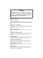
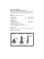
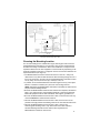
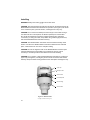
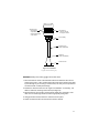
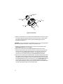
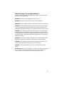
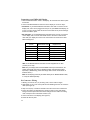
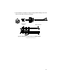
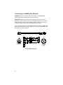
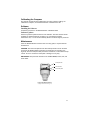
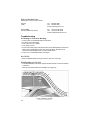
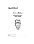
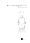
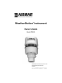
WeatherStation Instrument
®
Owner’s Guide
Model PB200
Record the serial number found on the
WeatherStation® instrument.
Serial No._________________________
Date of Purchase___________________
17-461-01 r01
01/01/08
Copyright © 2008 Airmar Technology Corp. All rights reserved.
Table of Contents
Introduction......................................................................................4
Safety Instructions........................................................................... 5
Adding an External Speed-Through-Water Sensor..........................6
Parts, Tools & Materials...................................................................7
Choosing the Mounting Location.................................................... 9
Installing........................................................................................ 10
Cable Routing & Connecting Guidelines...................................... 13
Connect to an NMEA 0183 Display.............................................. 14
Connect to an NMEA 2000® Network..........................................16
Calibrating the Compass................................................................ 17
Software......................................................................................... 17
Maintenance................................................................................... 17
Where to Purchase Parts................................................................ 18
Troubleshooting............................................................................. 18
Appendix A—How the WeatherStation® Instrument Works........ 20
Appendix B—Technical Information.............................................26
Acronyms & Glossary....................................................................27
3
IMPORTANT: Please read the Owner’s Guide completely
before proceeding with the installation.
Introduction
Thank you for purchasing the Airmar ultrasonic WeatherStation instrument. This
exciting product is actually six different sensors in a single unit—without any
moving parts. The compact housing is waterproof with a single removable cable.
Data is output in digital NMEA 0183 and NMEA 2000® formats.
Functions of the WeatherStation Instrument
• Apparent wind speed
• Apparent wind direction
• Magnetic compass heading
• Air temperature
• Wind chill temperature
• Rate of Turn
• Angle of vessel pitch
• Angle of vessel roll
• Barometric pressure
• Global Positioning System (GPS)
• Vessel speed over ground (SOG)
• Vessel course over ground (COG)
• True wind speed
• True wind direction
• Heading relative to true north
• True wind chill temperature
• True wind speed relative to water—requires speed-through-water input
4
WARNING
Navigation Aid Only—The WeatherStation instrument is
only an aid to navigation and should never be solely relied
upon. It is not a replacement for traditional navigation aids
and techniques. Only official government charts contain all
the information needed for safe navigation.
Safety Instructions
WARNING: Electrical Safety
The power supply voltage must be 12 VDC (±3VDC). Any other voltage may
damage the product and/or result in fire, damage to the boat, and/or personal
injury.
WARNING: Fuse or Circuit Breaker
A safe installation requires a 1 amp fast-blow fuse or circuit breaker. Failure to do
so may damage the product and/or result in fire, damage to the boat, and/or
personal injury.
WARNING: Installation Safety
Always wear safety goggles and a dust mask when installing to avoid personal
injury.
CAUTION: Correct Installation Important
The WeatherStation instrument must be installed and operated according to the
instructions in this owners guide. Failure to do so may result in poor product
performance.
CAUTION: Disassembly
Do not disassemble the sensor. Removing the screws from the WeatherStation
instrument will damage the waterproof seal, thus voiding the warranty.
IMPORTANT: Compass Safe Distance
The compass safe distance for standard and steering compasses is 1m (3').
Observe this distance to prevent interference to a magnetic compass.
MPORTANT: Calibrating the Compass
The internal compass must be calibrated. Failure to do so may result in inaccurate
compass readings.
IMPORTANT: Battery
Make power connections to a 12 VDC power source that is isolated from the
engine start battery(s). Voltage drops may cause the instrument to lose
information and/or change operating mode.
5
The Importance of Understanding True Wind Direction
When the WeatherStation instrument is stationary, the direction from which the
wind is blowing is known as the true wind. The WeatherStation instrument is
programed to measure the direction based upon the specific orientation of the
sensor. For the WeatherStation instrument to accurately calculate the true
direction of the wind, it must be installed and oriented correctly. (To learn more
about true and apparent wind direction, see Appendix A.)
Adding an External Speed-through-Water Sensor
The WeatherStation instrument can receive data from an external sensor when it
is connected through an optional NMEA 0183 Combiner or connected to an
NMEA 2000 network. An external speed sensor processes additional received
data and transmits it to the WeatherStation instrument for use in true wind
calculations. In the case of NMEA 0183 protocol, simply connect the sensor to an
NMEA 0183 Combiner or other NMEA 0183 repeater hardware. The data
provided can be seen on displays connected to the Combiner. An NMEA 2000
speed sensor can be connected to an NMEA 2000 network.
NOTE: When an external speed sensor is connected to both an NMEA 0183
device and an NMEA 2000 network, the WeatherStation instrument will use
NMEA 2000 data.
Speed-through-water sensor—An external speed sensor can be installed, such
as an Airmar Smart™ Sensor. Airmar recommends installing the DST800V to
receive water depth, boat speed, and water temperature data.
6
Parts, Tools & Materials
Cables, Converting, and Connecting Hardware
The WeatherStation instrument can be connected to a device and/or network in
several ways. You must have the correct cable and any needed junction box
before beginning the installation. Note that additional cable lengths are available.
Cables
NOTE: Additional cable lengths are available.
• NMEA 0183 Cable
• NMEA 2000® Cable
• NMEA 2000® Cable
10m
6m
10m
Part No. 33-862-02
Part No. 33-1029-02
Part No. 33-1029-06
Junction Boxes
•
•
•
•
•
NMEA 0183 to USB Converter
NMEA 0183 Combiner
NMEA 2000® CAN to USB Converter
NMEA 0183 & NMEA 2000® Junction Box Kit
NMEA 0183 & NMEA 2000® Junction Box Kit
Part No. 33-801-01
Part No. 33-800-01
15m
30m
Antenna Mount
Antenna mount with standard marine 1" -14 threads and pass-through for cable (see
Figure 1).
Hardware to install antenna mount
Extension tube (some installations).
deck mount
center pass-through
deck mount
side pass-through
ratchet mount
with extension tube
extension
with cable
pass-through
cable
passes
through
center
of mount
cable
passthrough
Figure 1. Antenna mounts (not supplied)
Copyright © 2007 Airmar Technology Corp.
7
Additional Tools and Materials
Safety goggles
Dust mask
Pencil
Level
Electric drill
Drill bits
Deck gland (some installations)
Phillips screwdrivers
Plumber’s tape (optional)
Grommets (some installations)
Cutting pliers (some installations)
Wire strippers (some installations)
Electrical tape (some installations)
Cable ties (some installations)
Where to Purchase Parts
Obtain parts from your instrument manufacturer or marine dealer.
Gemeco
(USA)
Tel: 843.394.3565
Fax: 843.394.3736
Email: [email protected]
Airmar EMEA
(Europe, Middle East, Africa)
Tel: 33.(0)2.23.52.06.48
Fax: 33.(0)2.23.52.06.49
Email: [email protected]
8
Min. 1m
Min. 1m
Figure 2. Antennas
Courtesy of Northstar BNT, Acton, MA
Choosing the Mounting Location
For accurate readings and a reliable GPS signal, selecting the best location for
the WeatherStation instrument is very important. Easy access and appearance
should be secondary considerations. Since each installation is unique, the best
separation distances from other equipment on the boat will vary depending on the
particular equipment and how it is configured. Choose a location that balances the
requirements below (see Figure 2).
• The WeatherStation instrument must be mounted in “clear air”—away from
obstructions in any direction that will interfere with air flowing through the unit. If
there is an obstruction, be sure to mount the WeatherStation instrument at least
2m (6') away. On land, avoid roof tops, chimneys, trees, etc.
• If possible, mount the WeatherStation instrument higher than any other object.
Mount it a minimum of 500mm (20") above the surrounding surfaces.
NOTE: The higher the WeatherStation instrument is mounted, the less accurate
the pitch and roll readings will be.
• Because the WeatherStation instrument has an electronic compass, it should be at
least 1 m (3') away from any on-board radar equipment or other strong magnetic
fields from equipment such as radio transmitters, boat engines, generators, etc.
• Because the WeatherStation instrument has a GPS, it must be lower than any
on-board INMARSAT communications antenna.
• Because the WeatherStation instrument has a GPS, be sure it is as far as
possible from high-powered transmitting antennas to avoid mutual interference.
• Because the WeatherStation instrument has a GPS, check for any
electromagnetic shading. That is, any obstructions from other vessels or
shoreline buildings that will interfere with the GPS signals that the
WeatherStation instrument must receive.
9
Installing
WARNING: Always wear safety goggles and a dust mask.
CAUTION: The blue metal plate and the blue film found in the wind channel of the
WeatherStation instrument are essential to its operation (see Figure 3). Be careful
not to scratch the plate, puncture the film, or damage them in any way.
CAUTION: Do not remove the waterproof connector(s) to ease cable routing. If
the cable must be cut and spliced, use Airmar’s splash-proof Junction Box
No. 33-035 and follow the instructions supplied. Removing the waterproof
connector(s) or cutting the cable, except when using a water-tight junction box,
will void the WeatherStation instrument warranty.
CAUTION: The WeatherStation instrument must be installed vertically—NOT
tilted to one side. If the WeatherStation instrument is tilted from the horizontal
plane, it will introduce an error in the compass reading.
CAUTION: Be sure the alignment tabs on the WeatherStation instrument point
forward toward the bow and parallel to the centerline of the boat. This is
necessary to accurately measure wind direction and vessel heading.
CAUTION: Do not tighten or align the WeatherStation instrument by rotating the
upper cap (see Figure 3). Turning may sever internal connections and void the
warranty. Grasp the lower housing below the blue metal plate. Hand-tighten only.
upper cap
waterproof film
wind channel
blue metal plate
lower housing
serial number
Figure 3. Wind channel
Copyright © 2008 Airmar Technology Corp.
10
WeatherStation
alignment tabs
face forward
and parallel to
the keel (centerline)
of the vessel
wind channel
where air travels
through the sensor
nut assembly
extension tube
(most installations)
cable exit
(some installations)
antenna mount
Figure 4. Installation
Copyright © 2007 Airmar Technology Corp.
WARNING: Always wear safety goggles and a dust mask.
1. Place the antenna mount at the selected location and mark the holes for the
screws (see Figure 1). Also, mark the hole in the center of the mount for the cable
to pass through. If you are using a ratchet mount, be sure you have purchased
an extension with a cable pass-through.
2. Position the antenna mount at a 90° angle to the waterline. If necessary, use
shims to make the mounting surface level (see Figure 4).
3. Drill the holes for the mounting screws and the cable exit if necessary. If the
cable is to be fed through the deck, install a high quality deck gland.
4. Using purchased screws, fasten the antenna mount in place.
5. Screw an extension tube onto the antenna mount if desired.
11
WeatherStation
connector
alignment
key
nut
assembly
captive
nut
Figure 5. Connecting
Copyright © 2007 Airmar Technology Corp.
6. With the nut assembly on the cable near the WeatherStation connector, thread
the cable through the extension tube (if used), antenna mount, and the cable
exit. Be sure to leave several inches of cable extending beyond the nut
assembly (see Figure 5).
CAUTION: If you use a thread lock, use plumber’s tape. Do not use a liquid thread
lock as it may weaken the plastic, causing it to swell and crack.
7. Screw the nut assembly onto the top of the antenna mount/extension tube.
Hand-tighten only. Do not over tighten.
8. Remove the caution label from the WeatherStation instrument’s socket.
Remove the protective cover from the connector. (Save the cap to protect the
connector, when the WeatherStation instrument is removed.) Plug the 9-pin
connector into the WeatherStation instrument. The alignment key on the
connector fits into a notch in the base of the WeatherStation instrument.
9. Grasp the lower housing of the WeatherStation instrument below the blue metal
plate. Being sure the alignment tabs are facing forward and parallel to the keel
(centerline) of the boat, slide the captive nut upward and screw it onto the base
of the WeatherStation instrument (see Figures 4 and 5). Hand-tighten only. Do
not over tighten. Be careful NOT to rotate the WeatherStation instrument or
loosen the nut assembly from the antenna mount/extension tube. Double check
to be sure the alignment tabs are still facing forward.
12
Cable Routing & Connecting Guidelines
You must read the safety instructions below before going to the section that is
appropriate for your equipment.
WARNING: Always wear safety goggles and a dust mask.
WARNING: The power supply voltage must be 12 VDC (±3VDC).
WARNING: A safe installation requires a 1 amp fast-blow fuse or circuit breaker.
CAUTION: To reduce electrical interference from other electrical wiring and any
on-board equipment with strong magnetic fields such as radar equipment, radio
transmitters, boat engines, generators, etc., separate the cables by at least 1m (3').
CAUTION: Do not remove the waterproof connector(s) to ease cable routing. If
the cable must be cut and spliced, use Airmar’s splash-proof Junction Box No.
33-035 and follow the instructions supplied. Removing the waterproof connector
or cutting the cable, except when using a water-tight junction box, will void the
instrument’s warranty.
CAUTION: Be careful not to tear the cable jackets when passing them through
bulkheads and other parts of the boat. Use grommets to prevent chaffing.
CAUTION: Use a multimeter to check the polarity and the connections to the
12VDC power supply before applying power to the instrument.
CAUTION: Coil any excess cable(s) and secure with cable ties to prevent
damage.
IMPORTANT: Make power connections to a 12 VDC power source that is isolated
from the engine start battery(s). Voltage drops may cause the instrument/
receiver/sensor to lose information and/or change operating mode.
13
Connecting to an NMEA 0183 Display
1. Route the WeatherStation cable to the display. Do not fasten the cable in place
at this time.
2. Connect the WeatherStation instrument to the display in one of two ways.
• Connector—If your WeatherStation instrument came with a connector on the
display end, and it can be plugged into the port on your NMEA 0183 display, do
so now. Coil any excess cable and secure it with cable ties to prevent damage.
Fasten the cable in place.
• No connector—If your WeatherStation instrument does not have a connector
on the display end, it must be hard wired. Refer to the owner’s manual that
came with your display and connect the colored wires as shown in the table
below and Figure 6.
WeatherStation
Function
WeatherStation Cable
Display Function
NMEA input A/+
Yellow
NMEA output A/+ (see Note 2)
NMEA input B/–
Orange
NMEA output B/–
NMEA output A/+
White
NMEA input A/+
NMEA output B/–
Blue
NMEA input B/–
12 VDC +
Red (see Note 1)
12 VDC + (see Note 3)
12 VDC –/ground
Black
12 VDC –/ground
Shield
Bare
Shield
Note 1: The WeatherStation instrument must be supplied with 12 VDC
(±3VDC) at 0.5 amp.
Note 2: If your display does not have NMEA 0183 output connections, the
yellow and orange wires are not needed and their ends should be taped
separately. (Alternatively, yellow and orange wires can be connected to an
external sensor.)
Note 3: The display power may be wired directly to the WeatherStation cable,
or it may be wired separately.
No Connector—Wiring
1. Allowing an extra 25 cm (10") for wiring ease, cut the cable to length.
2. Strip 60mm (2-1/2") of the outer jacket and foil shielding from the cut end of the
cable (see Figure 6).
3. Strip 10 mm (3/8") of conductor insulation from the end of each colored wire.
4. Protect the cable’s foil shielding from causing a short by using heat-shrink
tubing around the jacket where the wires emerge from the cable. The tubing
must overlap the wires a minimum of 6mm (1/4").
5. Connect the wires to the display (see Figure 6).
6. Fasten all cable in place.
14
7. Your installation is complete. To begin receiving weather readings, refer to the
owner’s manual that came with your display.
WeatherStation
connector
NMEA 0183 display
Figure 6. Wiring diagram to connect to an NMEA display
Copyright © 2007 Airmar Technology Corp.
15
Connecting to an NMEA 2000® Network
CAUTION: Only two termination resistors are required on an NMEA 2000
network. More than two will degrade the bus performance.
IMPORTANT: When using a cable that is longer than 6m (20'), remove the
termination resistor at the last node/tee on the NMEA 2000 network. Insert the
male-to-male pin into socket 5 of the WeatherStation connector to activate the
termination resistor located inside the WeatherStation instrument.
Route the WeatherStation cable to the NMEA 2000 network. Plug the NMEA 2000
connector into the network node (see Figure 7). Coil any excess cable and secure
with cable ties to prevent damage.
WeatherStation
connector
NMEA 2000
network
connector
Figure 7. NMEA 2000 cable
Copyright © 2008 Airmar Technology Corp.
16
Calibrating the Compass
The internal compass must be calibrated for accurate compass readings. To
calibrate the compass, use the WeatherCaster™ software and a PC.
Software
Installing the Software
Follow the instructions in the WeatherCaster™ Software Guide.
Software Updates
Airmar may release updated versions of the firmware. The latest revision will be
available for download through an email to you, from Airmar’s website,
www.airmar.com, or a CD can be mailed by Airmar’s technical support personnel.
Maintenance
Since the WeatherStation instrument has no moving parts, it requires minimal
maintenance.
CAUTION: The blue metal plate and the blue waterproof film found in the wind
channel of the WeatherStation instrument are essential to its operation (see
Figure 8). The blue waterproof film protects the transducers, so be careful to keep
it intact. Do not to scratch the metal plate or damage it in any way.
IMPORTANT: Keep the wind channel free of SPIDER WEBS, insects, dirt, and
other debris.
waterproof film
wind channel
blue metal plate
Figure 8. Wind channel
Copyright © 2008 Airmar Technology Corp.
17
Where to Purchase Parts
Obtain parts from your marine dealer.
Gemeco
(USA)
Tel: 843.394.3565
Fax: 843.394.3736
Email: [email protected]
Airmar EMEA
(Europe, Middle East, Africa)
Tel: 33.(0)2.23.52.06.48
Fax: 33.(0)2.23.52.06.49
Email: [email protected]
Troubleshooting
No Readings or Inaccurate Readings
•
•
•
•
•
Is there power to the WeatherStation instrument?
Are all the connections tight?
Is the cable-run free of kinks?
Is the wiring correct?
Are there any obstructions in the wind channel of the WeatherStation instrument?
Keep it free of spider webs, insects, dirt, and other debris. Be careful not to
puncture the blue waterproof film or scratch the blue plate.
• Is there ice on the WeatherStation instrument?
No GPS Fix
• Does the WeatherStation instrument have a clear view of the sky?
Wind Readings Are Too Low
• Is the WeatherStation instrument mounted forward and low on the boat’s hardtop
in dead air?
Move the instrument farther back and higher (see Figure 9).
Figure 9. Mounting location
Copyright © 2007 Airmar Technology Corp.
18
NMEA 0183 Combiner Problems
The LED light on the Combiner indicates its current operating mode and if an error
is detected during the self-test process. See the table below.
Color and
Flash Count
Mode and
Error Condition
Description of Mode and
Required User Action
Red
No flashing
Start-up mode
No error
Normal operation mode that should last for no
more than 1.5 seconds. Any longer indicates an
error with the program. No action required.
Red
No flashing
Flash Updating mode
No error
The LED will stay red for the duration of the flash
update operation. When the operation is
complete, the Combiner will automatically reset.
No action required.
Amber
No flashing
Initialize & Self-test mode
No error
Normal operation mode that follows the start-up
mode and should last for approximately 1 second.
No action required.
Green
No flashing
Normal & No Data mode
No error
Normal operation mode that follows the Initialize
& Self-test mode. Indicates that no error was
detected during self-test.
Also, no data is currently being received by the
Combiner. No action required.
Green
Flashing
(1–10 per sec.)
Normal & Data Receive
mode
No error
Normal operation mode that indicates data is
being received by the Combiner. The flash rate is
proportional to the Baud rate. No action required.
Amber
Flashing
(1 every 4 sec.)
Error Trap mode
EEPROM memory error
An error with the EEPROM memory has been
detected during the self-test mode.
Reset the Combiner by powering down, waiting
60 sec., then restarting the Combiner.
PC Problems
If you are uncertain of the COM port on your PC, follow the steps below.
1. From the Start menu, select Control Panels.
2. Select the System option.
3. Select the Hardware tab.
4. Select Device Manager.
5. Select Ports.
6. Select Airmar NMEA 0183 – USB Converter.
The Converter is powered when it is connected to the USB port on the PC.
19
Appendix A—How the WeatherStation Instrument Works
About the Ultrasonic Wind Sensor
The ultrasonic wind sensor (an ultrasonic anemometer) measures apparent wind
speed and direction. The WeatherStation instrument contains four ultrasonic
transducers, visible through the four holes in the top of the sensor’s wind channel
(see Figure 10). These transducers operate in pairs—one transducer injects a
pulse into the air. The pulse bounces off the metal plate at the bottom of the wind
channel and is carried by the wind to arrive at the listening transducer a short time
later.
4 transducers
behind waterproof film
wind channel
metal plate
Figure 10. WeatherStation ultrasonic wind sensor
Copyright © 2007 Airmar Technology Corp.
When there is no wind, the pulse travels at the speed of sound from the sender to
the receiver. Whenever the wind is blowing in that direction, the pulse will arrive
sooner than if the air is still. Similarly, whenever the wind is blowing in the
opposite direction, the pulse will arrive later than if the air is still. The four
transducers take turns in sending and receiving pulses.
A microprocessor within the WeatherStation instrument then combines the
measurements from all four transducers to calculate the resultant wind speed and
direction. Throughout this process, the sensor monitors the air temperature, to
compensate for the fact that the speed of sound in air changes with temperature.
Understanding True and Apparent Wind
The WeatherStation instrument has the unique ability to display both true and
apparent wind. True wind is the actual motion of the air relative to the earth.
Apparent wind is the wind which an observer experiences while moving or on
board a boat. It is the result of two motions—the actual motion of the air (the true
wind) and the motion of the boat. If the vessel is not moving, then the true and
apparent wind will be the same.
There are two components to any wind measurement: speed and direction. By
convention, the wind direction is an angle representing the direction from which
the wind is blowing. Sometimes this angle is referenced to true or magnetic north,
and sometimes it is referenced to the bow of the vessel. Both true and apparent
wind use these same references.
20
Consider the case of a vessel proceeding at a speed of 15 knots in calm air. An
observer on board would experience a wind of 15 knots from dead ahead. This
apparent wind would be due solely to the motion of the boat. If a true wind of 15
knots was blowing from the stern, an observer would experience dead calm—no
apparent wind. That is because the boat is moving at the same speed and in the
same direction as the surrounding air.
Now, consider the more complicated situation of a vessel proceeding at 15 knots
with a true wind of 15 knots blowing from the side (see Figure 11). To an observer
on board, the apparent wind would be 21.2 knots blowing from an angle 45º off
the bow.
15 knots
COG
21.2 knots
apparent wind
15 knots
true wind
Figure 11. Apparent wind
Copyright © 2007 Airmar Technology Corp.
In order to calculate the true wind speed and direction when on board a moving
vessel, it is necessary to know the apparent wind speed and direction, the speed
and course over ground of the vessel, the compass heading, and the local
magnetic variation. Note that heading and course are not the same thing: heading
is the direction the bow of the vessel is pointing, while course is the direction the
vessel is traveling. Heading and course may differ due to the effects of wind and
current. The WeatherStation instrument can provide true wind speed and direction
only if all of the data is available. The speed and course over ground must be
provided by a GPS receiver––either built-in or networked. The heading may be
provided by either the built-in electronic compass or by an external networked
compass.
Because true wind is calculated using the data from several sensors, its accuracy
depends on the accuracy of all the raw data used in the calculation. For instance,
if the electronic compass is located near iron or a similar magnetic disturbance,
the heading will be incorrect, and the true wind calculation will therefore be in
error, perhaps by quite a bit. In another example, the speed and course over
ground provided by the GPS receiver are averaged over time. If the boat is
performing maneuvers, changing speed and/or direction, then it will take a few
seconds for the SOG and COG values to "catch up". The reported true wind
values will therefore also be incorrect until the vessel reaches a steady-state
condition, traveling in a straight line at a constant speed.
21
About the Electronic Compass
The WeatherStation instrument includes three magnetoinductive sensors that
measure magnetic field-strength in three axes relative to the instrument. From
combined measurements of the three-axis magnetic and tilt sensors, it calculates
the resultant magnetic heading angle, thereby providing a built-in three-axis
electronic compass.
Like all magnetic compasses, the WeatherStation compass will be affected by any
ferrous or magnetic materials in the vicinity, such as metal structures, motors,
speakers, etc. It will also be affected by nearby electric fields, such as the wiring
for navigation lights or radar domes. These nearby sources of magnetic
interference will distort the magnetic field and produce errors in the compass
heading. These errors are known as magnetic deviation.
About Magnetic Variation and True Heading
The earth acts like a giant magnet, with a magnetic north pole and a magnetic
south pole. The axis of the magnetic poles is offset approximately 11.5° from the
axis of the earth's rotation. Therefore, the earth's magnetic north and south poles
are in different locations than the earth's geographic north and south poles. In
addition, the earth's magnetic field is non-uniform, and changes over time.
Magnetic variation, also known as magnetic declination, is the angle between
magnetic north and true (or geographic) north, at the observer's current location.
A magnetic compass measures heading with respect to magnetic north. To
convert this magnetic heading to true heading (that is, heading with respect to true
north), the magnetic variation must be added to the measured magnetic heading
value.
Because magnetic variation changes with location and gradually over time, it is
necessary to calculate the magnetic variation using the user's present position
and the current date. Therefore it is necessary to have a GPS with a fix in order to
provide magnetic variation and heading with respect to true north.
About the Air Temperature Sensor
The WeatherStation instrument includes a built-in negative-temperaturecoefficient thermistor that measures the ambient air temperature. This NTC
thermistor is located in a thermally isolated region of the WeatherStation housing
that is open to the outside air.
About Wind Chill Temperature
Wind Chill is a term that describes the heat loss on the human body resulting from
the combined effects of low temperature and wind. As wind speed increases, heat
is carried away from the body at a faster rate, causing a reduction in skin
temperature. Because the face is the part of the human body that is most likely to
be exposed, the wind-chill index is adjusted for the average adult face.
The concept of wind chill does not apply to inanimate objects, such as a boat. The
only effect that wind chill has in this case is to shorten the time it takes the object
to cool to the actual air temperature––wind chill does not cause an object to cool
below that temperature. For example, fresh water freezes at 0°C (32°F)
regardless of what the wind chill is.
22
The WeatherStation instrument calculates two values for wind-chill temperature:
one using the apparent wind-speed, and one using the true wind-speed. The
apparent wind-chill temperature is relevant to what an observer is currently
experiencing on the vessel. The true wind-chill temperature indicates what the
wind chill would be if the vessel were not moving.
Wind chill temperature is only defined for temperatures at or below 10°C (50°F)
and wind speeds above 2.6 knots (3MPH).
By default, transmission of wind-chill data is disabled by the WeatherStation
instrument. When used with WeatherCaster software, the wind-chill data will be
automatically enabled.
About the Barometric Pressure Sensor
The WeatherStation instrument contains a temperature-compensated, silicon,
piezoresistive, pressure sensor. It measures atmospheric pressure for use as a
digital barometer. While a single measurement of air pressure at a given location
has little value, the trend of changing pressure and wind over time can be a useful
tool in performing basic weather forecasting.
About the GPS
Some WeatherStation instruments have a built-in Global Positioning System with
their own antenna, receiver, and position determining electronics. The GPS
receiver receives radio signals from a constellation of orbiting satellites
maintained by the U.S. government. By accurately measuring the time it takes for
a transmission to travel from each satellite to the receiver, the unit is able to
determine the distance between the satellite and the receiver. When the distance
is known to three satellites, the unit is able to calculate the latitude and longitude
of the receiver. This is known as a 2D fix. If the distance is known to four or more
satellites, then the unit is additionally able to calculate the altitude of the receiver.
This is known as a 3D fix.
The GPS receiver in the WeatherStation instrument takes approximately one
minute on average to achieve a position fix after power is first applied. This is
known as the "time to first fix."
The GPS receiver synchronizes itself to the atomic clocks on board each satellite.
This allows the GPS receiver to accurately determine the date and time as well.
If the GPS receiver is mounted on a moving vessel, its changing position over
time allows the speed and course over ground to be calculated. The course
reported by a GPS is always with respect to true north.
The ability of the WeatherStation instrument to calculate true wind speed and
direction depends on the presence of a GPS fix. If the GPS receiver is not tracking
at least three satellites, then the WeatherStation instrument will be unable to
provide true wind data. (Apparent wind data should always be available,
regardless of the status of the GPS receiver.)
Certain models of the WeatherStation instrument do not include a built-in GPS
receiver. In this case, if the true wind capabilities of the WeatherStation instrument
are desired, it will be necessary to connect the output from an external NMEA
0183-capable GPS to the NMEA input on the WeatherStation instrument (or to the
23
optional Combiner), in order to enable the true wind capabilities of the
WeatherStation instrument.
Even if your WeatherStation instrument includes a built-in GPS receiver, you may
wish to use a separate external GPS receiver instead, for the determination of true
wind. If the WeatherStation instrument receives speed over ground and course
over ground (SOG and COG) data on its NMEA input from an external GPS, these
data will override the data from the built-in GPS for the purpose of calculating true
wind speed and direction. In addition, the WeatherStation instrument will
automatically suppress transmission of GPS messages from its own built-in GPS
receiver.
About True Wind Relative to Water
If a fix from a GPS receiver is not available, it is still possible for the
WeatherStation instrument to determine a value for true wind, if the speed of the
vessel through the water is known. In this case, it is necessary that a water-speed
sensor with an NMEA output (such as an Airmar Smart™ Sensor) be connected
to the NMEA input on the WeatherStation instrument (or to the optional
Combiner).
The WeatherStation instrument's calculation for true wind relative to water makes
the significant simplifying assumption that the vessel's course is the same as its
heading. That is, the effects of wind and current on the motion of the boat are
ignored. The direction of the true wind relative to water is referenced only to the
bow of the vessel, not to true or magnetic north.
24
Appendix B—Technical Information
NMEA 0183 Sentence Commands
* These sentences are enabled at the factory.
$GPDTM
$GPGGA *
$GPGLL
$GPGSA
$GPGSV
$HCHDG
$HCHDT
$WIMDA *
$WIMWD
$WIMWV *
$WIMWV
$GPRMC
$TIROT *
$GPVTG *
$WIVWR
$WIVWT
$YXXDR
$GPZDA *
$PFEC, GPatt *
$PFEC, pidat
Datum Reference
GPS Fix Data
Geographic Position –Latitude/Longitude
GNSS DOP and Active Satellites
GNSS Satellites in View
Heading, Deviation and Variation
Heading True
Meteorological Composite. Barometric Pressure,
Air Temperature, Wind Direction, Wind Speed
Wind Direction and Speed, with respect to north
Wind Speed and Angle, in relation to the vessel’s bow
/centerline (relative)
Wind Speed and Angle, in relation to the vessel’s bow
/centerline (theoretical)
Recommended Minimum Specific GNSS Data
Rate of Turn
Course Over Ground and Ground Speed
Relative Wind Speed and Angle
True Wind Speed and Angle
Transducer Measurements: Wind Chill and Vessel Attitude
Time and Date
Heading, Pitch, and Roll
Additional Data Available from the WeatherStation Instrument
There are parameters that the WeatherStation instrument can make available to
the user. Usually, more data is available from the WeatherStation instrument than
can be displayed in a reasonable format on a screen. Also, if all the data was
continuously transmitted to the display, the update rate would be too slow and
could not keep up with WeatherStation measurements. Consequently, some
parameters are transmitted while others are not, based on a pre-selected list—the
NMEA 0183 sentences with an asterisk. Note that those parameters not
transmitted are, nevertheless, retained in the WeatherStation instrument. For
more detailed information, see the “Technical Manual” on the WeatherStation CD.
NMEA 2000® PGN Commands
Transmitted NMEA 2000® PGNs
PGN 059392
PGN 060928
PGN 065285
PGN 065287
PGN 126208
PGN 126464
PGN 126720
PGN 126720-32
ISO Acknowledgment
ISO Address Claim
Proprietary: Boot State Acknowledgment
Proprietary: Access Level
Acknowledge Group Function
PGN List - Transmit/Received PGN's Group
Addressable Multi-Frame Proprietary
Proprietary: Attitude Offsets
25
PGN 126720-33
PGN 126720-34
PGN 126720-35
PGN 126720-49
PGN 126720-50
PGN 126992
PGN 126996
PGN 126998
PGN 127250
PGN 127251
PGN 127257
PGN 127258
PGN 129025
PGN 129026
PGN 129029
PGN 129033
PGN 129044
PGN 129538
PGN 129539
PGN 129540
PGN 130306
PGN 130310
PGN 130311
PGN 130323
PNG 130822
PNG 130823
PGN 130880
PGN 130881
PGN 130944
PGN 65281
Proprietary: Calibrate Compass
Proprietary: True Wind Options
Proprietary: Simulate Mode
Set WAAS Satellite
Set Tzz Parameter
System Time
Product Information
Configuration Information
Vessel Heading
Rate of Turn
Attitude
Magnetic Variation
Position, Rapid Update
COG & SOG, Rapid Update
GNSS Position Data
Time & Date
Datum
GNSS Control Status
GNSS DOPs
GNSS Sats in View
Wind Data
Environmental Parameters
Environmental Parameters
Meteorological Station Data
Unit Division Code (FEC)
Browser Control Status (FEC)
Proprietary: Additional Weather Data
Proprietary: Heater Control
Proprietary: POST
Terminator Status (FEC)
Received NMEA 2000® PGNs
PGN 059904
PGN 060928
PGN 065286
PGN 126208
PGN 126208
PGN 126720
PGN 126720-1
PGN 126720-130
PGN 126720-132
PGN 128259
PGN 126208
PGN 130821
ISO Request
ISO Address Claim
Proprietary: Boot State Request
Request Group Function
Command Group Function
Addressable Multi-Frame Proprietary
Proprietary: Master Reset
Proprietary: Reset EEPROM
Proprietary: Reset GPS
Speed
WAAS ON/OFF
NavSource Speed (FEC)
Additional Data Available from the WeatherStation Instrument
There are parameters that the WeatherStation instrument can make available to
the user. Usually, more data is available from the WeatherStation instrument than
can be displayed in a reasonable format on a screen. Consequently, some
parameters are transmitted while others are not. Note that those parameters not
26
transmitted are, nevertheless, retained in the WeatherStation instrument. For
more detailed information, see the “Technical Manual” on the WeatherStation CD.
Baud Rate
WeatherCaster™ software needs the baud rate to be set as follows:
NMEA 0183 USB Converter
baud rate 4800.
NMEA 0183 Combiner
baud rate 38400.
Load Equivalency Number
LEN......................... 13
Calibration
The WeatherStation instrument is calibrated at the factory and does not require
any calibration after purchase.
Acronyms
CD
COG
COM Port
DOP
GNSS
GPS
LED
LEN
PC
SOG
UNS
USB
WAAS
2D
3D
Compact Disk
Course Over Ground
Communications Port
Dilution Of Precision
Global Navigation Satellite System
Global Positioning System
Light Emitting Diode
Load Equivalency Number
Personal Computer
Speed Over Ground
Unified National Standard
Universal Serial Bus
Wide Area Augmentation System
Two Dimensional GPS Fix
Three dimensional GPS Fix
Glossary
Firmware
WeatherCaster™ software
The software within the WeatherStation hardware
The PC application program
Trademarks
Airmar® is a registered trademark of Airmar Technology Corporation.
NMEA 2000® is a registered trademark of the National Marine Electronics Assoc.
Smart™ Sensor is a trademark of Airmar Technology Corporation.
WeatherCaster™ is a trademark of Airmar Technology Corporation.
WeatherStation® is a trademark of Airmar Technology Corporation.
27
35 Meadowbrook Drive, Milford, New Hampshire 03055-4613, USA
www.airmar.com
28