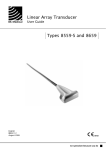
1
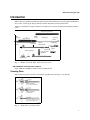
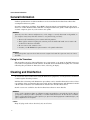
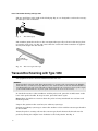
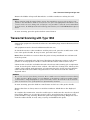
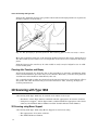
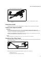
Endosonic Probe
User Guide
Type 1850
English
BB0096-M
August 2006
WORLD HEADQUARTERS
Mileparken 34
DK-2730 Herlev
Denmark
Tel.:+45 44528100 / Fax:+45 44528199
www.bkmed.com
Email: [email protected]
If you have comments about the user documentation, please write to us at the email address above.
We would like to hear from you.
BK Medical Customer Satisfaction
Input from our customers helps us improve our products and services. As part of our customer
satisfaction program, we contact a sample of our customers a few months after they receive their
orders. If you receive an email message from us asking for your feedback, we hope you will be
willing to answer some questions about your experience buying and using our products. Your
opinions are important to us. You are of course always welcome to contact us via your BK Medical
representative or by contacting us directly.
© 2006 BK Medical
Information in this document may be subject to change without notice.
Endosonic Probe Type 1850
Introduction
Scanning Plane
General Information
1
1
2
Caring for the Transducer
2
Cleaning and Disinfection
2
Starting Scanning
3
Connecting the Transducer
Using a Transducer Cover
Using the Transducer Control Button
Changing Orientation
Assembling Type 1850 for Transurethral Use
Assembling Type 1850 for Transrectal Use
Single-Use Rectosigmoidoscope UA0681
3
3
3
3
4
4
7
Transurethral Scanning with Type 1850
8
Transrectal Scanning with Type 1850
9
Puncture Facilities
10
Mounting the Perineal Puncture Attachment UA0650
10
Performing Puncture and Biopsy
10
Transperineal Biopsy
Cleaning after Puncture and Biopsy
11
12
3D Scanning with Type 1850
3D Scanning using Mover Support
Pullback Mover UA0552
Variable Friction Support Arm UA0553
Assembly and Use of Mover Support
Attaching the Fixation Clamp to the Examination Bed
12
12
13
13
13
14
Attaching the Fixation Clamp to the Support Arm
Attaching the Instrument Clamp to the Support Arm
Maneuvering the Support Arm
Disposal
14
15
15
15
Endosonic Probe Type 1850
Endosonic Probe Type 1850
Introduction
This is the user guide for Endosonic Probe Type 1850 and must be used together with Transducer Care, Cleaning & Safety which contains important safety information.
1850 is a mechanical (single-element) transducer for anorectal and transurethral examinations.
Cable and Plug
Cable
Connection
Transport Protection Cover
Adaptor
Thread
Motor Housing
Control
Button
Rectal Tube
Rotating Rod
Fixture for
Rubber Sheath
Rectal
Transducer
Urethral Transducer
Perineal Puncture
Attachment
Transducer
Mount
Sealing Rings
Rubber
Sheath
Hardcone
Sheath Adaptor
Fig. 1.
Endosonic Probe Type 1850 with accessories
FDA WARNING for the United States of America
Type 1850 should not be used for fetal examinations.
Scanning Plane
The endosonic probe has three transducer attachments. See Fig. 2. for details.
Fig. 2.
Transducers for Type 1850
1
1850 • General Information
General Information
Product specifications for this transducer can be found in the Product Data sheet that
accompanies this user guide.
Acoustic output data and data about EMC (electromagnetic compatibility) for this transducer are on the Technical Data CD that accompanies this user guide. A full explanation of
acoustic output is given in your scanner user guide.
WARNING
If at any time the scanner malfunctions, or the image is severely distorted or degraded, or
you suspect in any way that the scanner is not functioning correctly:
• Remove all transducers from contact with the patient.
• Turn off the scanner. Unplug the scanner from the wall and make sure it cannot be
used until it has been checked.
• Do not remove the scanner cover.
• Contact your B-K Medical representative or hospital technician.
WARNING
Always keep the exposure level (the acoustic output level and the exposure time) as low as
possible.
Caring for the Transducer
The transducer may be damaged during use or processing, so it must be checked before use
for cracks or irregularities in the surface. It should also be checked thoroughly once a month
following the procedure in Transducer Care, Cleaning & Safety.
Cleaning and Disinfection
To ensure the best results when using B-K Medical equipment, it is important to maintain
a strict regular cleaning routine.
Full details of cleaning and disinfection procedures can be found in Transducer Care, Cleaning & Safety that accompanies this user guide. A list of disinfectants and disinfection methods that the transducer can withstand are listed in the Product Data sheet.
Sterile covers are available. See the Product Data sheet for more details.
WARNING
Users of this equipment have an obligation and responsibility to provide the highest degree
of infection control possible to patients, co-workers and themselves. To avoid cross contamination, follow all infection control policies for personnel and equipment established for your
office, department or hospital.
Caution
Keep all plugs and sockets absolutely dry at all times.
2
1850 • Starting Scanning
Starting Scanning
All equipment must be cleaned and disinfected before use.
Connecting the Transducer
WARNING
Keep all plugs and sockets absolutely dry at all times.
Unscrew the connector plug cover on the transducer (if attached). On the connector plug,
make sure that the red arrow is aligned with the red dot on the transducer socket. Pull back
the outer locking mechanism and insert the plug in the socket. Release the locking mechanism to secure in place.
When connected the transducer complies with Type B requirements of EN60601-1 (IEC
60601-1).
Using a Transducer Cover
The transducer should be enclosed in a transducer cover or a standard condom. See the
Product Data sheet for a list of available transducer covers.
Note: Sterile, disposable sheaths are recommended for intraoperative use. In the United
States of America, it is recommended that probe sheaths have been market-cleared. In Canada, use only licensed probe sheaths.
WARNING
Because of reports of severe allergic reactions to medical devices containing latex (natural
rubber), FDA is advising health-care professionals to identify their latex-sensitive patients
and be prepared to treat allergic reactions promptly.
Note: For Intraoperative Applications
Apply sterile gel to the tip of the transducer or fill the cover with 1 to 2ml of sterile water.
This improves the screen images by preventing image artifacts caused by air bubbles.
Pull the transducer cover over the transducer.
WARNING
Use only water-soluble agents or gels. Petroleum or mineral oil-based materials may harm
the cover material.
Using the Transducer Control Button
The transducer has a control button that you can press to Start or Stop scanning (freeze
frame). Press the button for more than one second to make a copy of the image.
Each time the button is pressed, a “beep” is emitted.
Changing Orientation
To change the orientation of the image on the monitor, refer to the applicable scanner user
guide for instructions.
3
1850 • Starting Scanning
Assembling Type 1850 for Transurethral Use
Type 1850 can use a Storz 24Fr. resectoscope, which is shown in Fig. 3. The resectoscope is
attached to the probe using the appropriate adaptor.
Fig. 3.
Storz 24Fr. resectoscope
Slide the appropriate resectoscope adaptor over the probe’s rotating rod as shown in Fig. 4.
Align the slot inside the adaptor with the small nodule on the probe. Push firmly into position and tighten by turning the adaptor’s ridged neck until it closes tightly against the
probe’s handle.
IP57 mark indicating watertight and image-direction
Thread
Nodule
Fig. 4.
Adaptor Lever
Fitting Type 1850 with the resectoscope adaptor
Select the urethral transducer, locate the small nodule on the transducer, align it with the
slot at the end of the probe’s rotating rod and push the transducer firmly into place (see Fig.
5.). When correctly connected, the transducer and the rod will form a flat surface.
Slot
Fig. 5.
Nodule
Fitting Type 1850’s rotating rod with one of the transurethral transducers
The 12 o’clock position on the displayed image will be in the direction of the midline between
the P and the 5 (part of the IP57 watertight symbol) on the probe’s handle.
The arrow shows the alignment position
.
IP57
The watertight symbol (IP57) should usually point in the ventral direction of the patient as
shown in Fig. 4.
Assembling Type 1850 for Transrectal Use
To assemble the probe for transrectal scanning, remove the sealing rings from the appropriate rectal tube and slide it over the probe’s rotating rod (see Fig. 6.). Align the slot inside the
4
1850 • Starting Scanning
threaded collar of the rectal tube with the nodule on the probe and push firmly into position.
Turn the collar on the rectal tube until it closes tightly against the probe’s handle.
WARNING
It is essential for patient safety that the correct rectal tube is used together with the appropriate transducer head.
Endosonic Probe Type 1850
Sealing Rings
Rectal Tube
Rectal
Transducer
Rubber Sheath
UA 0799
Perineal Puncture Attachment
Hard
Cone
Fig. 6.
Type 1850 with accessories for transrectal scanning and perineal puncture
Locate the nodule on the transducer. Align it with the slot at the end of the probe’s rotating
rod and push the transducer firmly into position (see Fig. 5.). Check the transducer is secure
by rotating it. When correctly connected, the transducer and the rod will form a flat surface.
When the probe is assembled for transrectal scanning, check the rotation of the transducer
and the probe’s rod before the rubber sheath is fitted. To start the rotation, press the builtin control button on the base of the probe’s handle. To stop rotation, press the button again.
Fitting a Rubber Sheath
Slide a rubber sheath (UA0799) over the transducer and, as far as possible, over the rectal
tube (picture 1).
Slide the sealing rings over the sheath (picture 2).
5
1850 • Starting Scanning
Pull the rubber sheath out gently at the exposed end and screw the sealing rings tight to the
rectal tube (picture 3).
Fill the rubber sheath with approximately 50ml of degassed (lukewarm boiled) water
through the valve on the rectal tube.
Note: Do not use sterile water.
Air bubbles may appear in the rubber sheath. As air bubbles will disrupt the path of the
ultrasound beam and cause image artifacts, they must be removed.
To remove all the air from the rubber sheath, hold the probe with the rubber sheath pointing
downwards (see Fig. 7.) and draw off as much air as possible using the syringe. Refill the
rubber sheath with degassed water. Repeat this procedure until there is no air left in either
the sheath or the water outlet. Then draw all the water out of the rubber sheath.
Fig. 7.
Removal of air bubbles from the rectal tube and rubber sheath
Fitting the Plastic Hood WA0543 or EA4020
Slide a plastic hood over the transducer and screw it reasonably tight to the rectal tube.
6
1850 • Starting Scanning
Fill the plastic hood with approximately 10-20ml of degassed (lukewarm boiled) water
through the valve on the rectal tube.
Note: Do not use sterile water.
Air bubbles may appear in the plastic hood. As air bubbles will disrupt the path of the ultrasound beam and cause image artifacts, they must be removed.
To remove all the air from the plastic hood, hold the probe with the plastic hood pointing
upwards and slowly inject more water using a syringe. Continue this procedure until there
is no air left in either the plastic hood or the water outlet. Make sure that the 0.15mm air
vent hole in the distal end of the plastic hood is not blocked.
The 12 o’clock position on the displayed image will be in the direction of the midline between
the P and the 5 (part of the IP57 watertight symbol) on the probe’s handle.
The arrow shows the alignment position
.
IP57
The watertight symbol (IP57) should usually point in the ventral direction of the patient as
shown in Fig. 4.
EA4020 can be autoclaved or disinfected by immersion in a suitable solution. Do not exceed
20 cycles. WA0543 can be disinfected by immersion in a suitable solution.
Single-Use Rectosigmoidoscope UA0681
The single-use rectosigmoidoscope UA0681 is designed to be used with Type 1850 to examine the rectum. Prepare the equipment as described earlier. See “Assembling Type 1850 for
Transrectal Use” on page 4.
The single-use rectosigmoidoscope, obturator and grip (UA0681) are ETO-sterilized in the
package and ready to use. The reusable light source cable adaptor UA0682 is delivered nonsterile, but it can be sterilized in a steam autoclave.
To use the light source cable adaptor UA0682, insert the closed end into the hollow handle
of the black grip (Fig. 8.). Use the appropriate adaptor ring to connect a light cable.
grip
UA0682
Fig. 8.
The single-use rectosigmoidoscope UA0681
7
1850 • Transurethral Scanning with Type 1850
The two small fins on the right of the black grip (Fig. 9.) are designed to anchor the rectosigmoidoscope to the transducer.
fins
Fig. 9.
The black grip
The numbers printed in italics on the rectosigmoidoscope tell you how far the image plane
is from the anal verge (see Fig. 10.). Note that the actual end of the transducer is approximately 1cm deeper into the rectum.
italics indicate
distance to image
plane
Fig. 10.
The rectosigmoidoscope
Transurethral Scanning with Type 1850
All equipment must be cleaned and disinfected before use.
WARNING
Transurethral scanning with Type 1850 implies no greater risk of perforating the bladder
wall than does normal cystoscopy. However, care must be taken to ensure that the bladder is
not damaged by the tip of the transducer which protrudes 10 to 12mm in front of the origin
of the ultrasound beam (i.e. in front of the scan center as seen on the screen).
To check the rotation of the transducer and the probe’s rod, press the round button on the
base of the probe’s handle. To stop rotation, press the button again.
Note: There should be no rotation when the probe is being introduced into and removed
from the patient.
Prepare the patient in the usual way for ordinary cystoscopy.
Perform an ordinary cystoscopy to ensure the urethra is clear and the resectoscope sheath is
in the bladder.
Insert the probe’s rotating rod into the resectoscope sheath. Fasten the sheath onto the
probe by turning the adaptor lever clockwise to the lock position. See Fig. 4.
8
1850 • Transrectal Scanning with Type 1850
Ensure the bladder is kept well distended to avoid the transducer touching the wall.
WARNING
When scanning with the 1850, always ensure the transducer set-up on the monitor corresponds to the transducer head in use. If it does not, press the appropriate transducer select
control on the console to change the set-up. If it is not possible to select the correct transducer
from the menu, do NOT proceed with scanning and contact your local B-K Medical representative.
To start scanning, press the probe’s built-in control button.
Transrectal Scanning with Type 1850
Prepare the equipment as described earlier. See “Assembling Type 1850 for Transrectal Use”
on page 4.
All equipment must be cleaned and disinfected before use.
To check the rotation of the transducer and the probe’s rod, press the round button on the
base of the probe’s handle. To stop rotation, press the button again.
Note: There should be no rotation when the probe is being introduced into and removed
from the patient.
The patient is examined in the left lateral decubitus, the lithotomy position or the prone
position. A rectal palpation is made to ensure that the lumen of the rectum is clear.
Lubricate the rectal tube and rubber sheath or hard cone with scanning gel or exploration
cream. Cover the probe with an extra condom – this will ease cleaning later. Lubricate the
outside of the condom with exploration gel and insert the probe in the usual way. Fill the
rubber sheath with about 50ml of degassed water or the hard cone with 10 – 20ml of
degassed water.
WARNING
Do not use excessive force during insertion. Do not make excessive lateral movements during
or after insertion. Risk of injury or tissue damage to the patient could occur under certain
circumstances. A digital palpation of the rectum may need to be carried out by a clinician
prior to insertion or use of the probe as a precautionary measure.
To start scanning, press the built-in control button at the base of the probe’s handle.
Ensure that there is always water around the transducer. Check this on the displayed
image.
To complete the examination, scan the caudal region to make sure the anus has not ligated
the passage. When you are sure the passage is free, press the button at the base of the
probe’s handle to stop scanning. Ensure the probe has stopped rotating. Empty the water
from the rubber sheath, if used, using a syringe and withdraw the probe.
9
1850 • Puncture Facilities
Puncture Facilities
Puncture and biopsy are possible with Type 1850. The puncture attachment is illustrated in
the following pages with a brief description of its uses and operating instructions.
For hygiene reasons, the transducer should be enclosed in a transducer cover or a standard
condom. When sterile conditions are required, cover it with a sterile transducer cover.
WARNING
It is essential for the patient’s safety that only the correct puncture attachment is used with
Type 1850. Never use unauthorized combinations of transducers and puncture attachments
or other manufacturers’ puncture attachments.
Mounting the Perineal Puncture Attachment UA0650
Loosen the thumb screw on the puncture attachment UA0650. Fit the puncture attachment
on the rectal tube at a suitable position. Tighten the thumb screw. See Fig. 11.
Fig. 11.
Type 1850 assembled for transrectal scanning with puncture attachment UA0650
All parts of the puncture attachment can be autoclaved or disinfected by immersion in a
suitable solution.
Performing Puncture and Biopsy
WARNING
It is essential for the patient’s safety that only the correct puncture attachments, as described
in this guide, are used. Never use unauthorized combinations of transducers and puncture
attachments or other manufacturers puncture attachments.
Before beginning a puncture or biopsy procedure, always check that the type number of the
transducer and the type number or description of the puncture attachment match exactly
those displayed on the scanner monitor.
WARNING
The row of puncture markers on the scan image is an indication of the expected needle path.
However, the needle tip echo will not be seen before the tip actually is in the transaxial image
plane.
Cover the transducer with a sterile transducer cover.
If the transducer cover is damaged when attaching the puncture attachment, replace it with
a new cover.
10
1850 • Performing Puncture and Biopsy
Note: Sterile, disposable sheaths are recommended for intraoperative use; and in the U.S.A.
it is recommended that probe sheaths have been market-cleared. In Canada, use only
licensed probe sheaths.
See the Product Data sheet for a list of available transducer covers.
Press the scanner Puncture or Biopsy control button to superimpose a row of puncture markers on the scan image.
Move the transducer until the row of puncture markers transects the target. Insert the needle. The needle tip echo will be seen as a bright dot on the screen.
WARNING
If the needle guide is detached from the transducer during interventional procedures, cover
the transducer with a new transducer cover.
To remove the row of puncture markers from the scan image, refer to the applicable scanner
user guide for instructions.
WARNING
Remember that the endosonic probe must have stopped rotating before you attempt to remove
it.
WARNING
When performing a biopsy, always make sure that the needle is fully drawn back inside the
needle guide before moving the probe.
WARNING
If rotation of the shaft is obstructed by pushing hard on the transducer head or the shaft, the
image orientation may be disturbed (rotated).
Do not perform punctures under these circumstances.
There is no problem if the overload protection is activated and stops the rotation of the
shaft. Correct image orientation can be secured by stopping and restarting the transducer.
Transperineal Biopsy
For transperineal biopsy, place the patient in either the lithotomy or the left lateral decubitus position. The perineum is prepared for puncture and anesthetized.
Fit the perineal puncture attachment to the endosonic probe, insert the probe into the rectum. It is recommended that it is held fast on a fixation unit.
Press the scanner’s Puncture control button to superimpose a row of puncture markers on the
scan image. If there is more than one puncture guide available for the transducer, press the
appropriate control button on the ultrasound scanner to select the required row of puncture
markers.
11
1850 • 3D Scanning with Type 1850
Refer to the applicable scanner user guide for the method of changing which row of puncture
markers appears on the monitor.
Fig. 12. The principle for perineal puncture. The scanning plane within the body is shown
Move the transducer until one of the puncture markers transects the target. Insert the needle. The needle tip echo will be seen as a bright dot on the screen once it transects the image
plane.
Take the biopsy in the usual way. If a fine needle is used, it may be helpful to use an additional needle guide.
Cleaning after Puncture and Biopsy
If biological materials are allowed to dry on the transducer or puncture attachments, disinfection and sterilization processes may not be effective. Therefore, you must clean puncture
attachments and transducers immediately after use.
Use a suitable brush to make sure that biological material and gel are removed from all needle guides and other channels and grooves. See Transducer Care, Cleaning & Safety for
cleaning instructions.
3D Scanning with Type 1850
3D scanning with Type 1850 may be carried out in either of two ways:
• Freehand – where Type 1850 is combined with the appropriate 3D scanner software.
• Using mover support – where Type 1850 is combined with the appropriate 3D scanner
software, the Pullback Mover UA0552 and the Variable Friction Arm UA0553.
3D Scanning using Mover Support
3D scanning with Type 1850 using Mover Support is carried out using:
• The appropriate 3D scanner software.
• The Pullback Mover UA0552.
12
1850 • 3D Scanning with Type 1850
• The Variable Friction Arm UA0553.
Fig. 13.
Type 1850 and Pullback Mover UA0552 mounted on Variable Friction Arm
UA0553
Pullback Mover UA0552
Further information about the Pullback Mover UA0552 can be found in the user guide.
Variable Friction Support Arm UA0553
Maintenance
Periodically check that all screws on the Variable Friction Support Arm UA0553 are
securely fastened and that all joints are adequately lubricated with standard lubricant oils
or grease to ensure their continued performance.
Contact your B-K Medical representative if you believe the correct functioning of the Variable Friction Support Arm is impaired in any way.
Caution:
The Variable Friction Support Arm must not be immersed or autoclaved.
Assembly and Use of Mover Support
The Pullback Mover UA0552 is mounted on the examination bed using the Variable Friction
Support Arm UA0553.
Fig. 14.
Variable Friction Support Arm UA0553
The Variable Friction Support Arm UA0553 (see Fig. 14.) consists of:
• A Support Arm (A);
• Two identical fixation clamps (B and C);
13
1850 • 3D Scanning with Type 1850
• A variable friction wheel (D).
One of the two fixation clamps (B or C) is used to secure the support arm to the examination
table (the support clamp) with the other fixation clamp being used to secure the Pullback
Mover to the Support Arm (the instrument clamp).
The Support Arm can be manipulated so that the Pullback Mover is optimally positioned
with respect to the patient. It can also be locked into position, thus preventing accidental
movement of the setup.
UA0553 fits onto the rail along the side of the examination bed or onto the bed itself.
UA0553 should be positioned so that the Pullback Mover will easily reach the patient.
Fig. 15.
Fixation Clamp
Attaching the Fixation Clamp to the Examination Bed
The fixation clamp is shown in Fig. 15. Turning the handle (E) in a clockwise direction tightens the jaws of the clamp to match the dimensions of the mounting rail or of the operating
table itself.
Attaching the Fixation Clamp to the Support Arm
The clamp has a hand-screw (F) and a security pin (G) on the upper jaw, which control the
attachment of the Support Arm.
At each end of the support arm are universal ball joint brackets (H), which rotate 360o (see
Fig. 16.). To attach the bracket to the support clamp:
• Loosen the hand-screw (F) by turning counterclockwise
• Insert the distal end of the bracket into the socket on the top of the support clamp
while depressing the security pin (G).
To remove, reverse the procedure.
Fig. 16.
Universal Ball Joint Bracket at the end of the Support Arm
With the joint inserted into the socket on the support clamp, the arm is secured by tightening the handscrew (F) in a clockwise direction.
14
1850 • Disposal
Attaching the Instrument Clamp to the Support Arm
The clamp has a hand-screw (F) and a security pin (G) on the upper jaw, which control the
attachment of the Support Arm (see Fig. 15.).
At each end of the support arm are universal ball joint brackets (H), which rotate 360o (see
Fig. 16.).
The joint is attached to the support clamp by loosening the hand-screw (F) by turning counterclockwise and inserting the distal end of joint into the socket on the top of the support
clamp while depressing the security pin (G).
To remove, reverse the procedure.
Maneuvering the Support Arm
The support arm has a universal ball joint midway along its shaft. The Variable Friction
Wheel (D) is used to fix the precise position and the setting of the arm. Tightening the wheel
by turning in a clockwise direction secures the settings of all of the universal ball joints in
the arm – in the mid-point and at both ends.
The setup can now be moved over into the patient area.
Caution:
All hand wheels and screws should be locked before any interventional procedure, thus preventing accidental movement of the setup.
Disposal
When the transducer is scrapped at the end of its life, national rules for the relevant material in each individual land must be followed. Within the EU, when you discard the transducer, you must send it to appropriate facilities for recovery and recycling. See the
applicable scanner user guide for further details.
WARNING
For contaminated disposals such as transducer covers or needle guides, follow disposal control policies established for your office, department or hospital.
15
1850 • Disposal
16