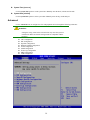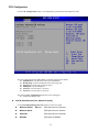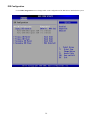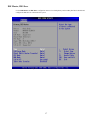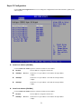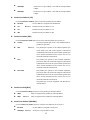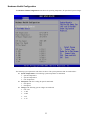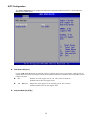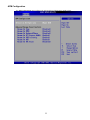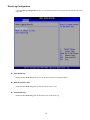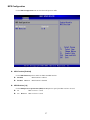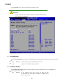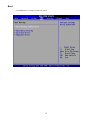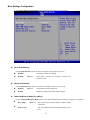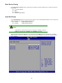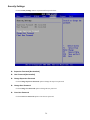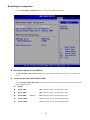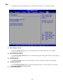
1
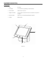
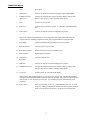
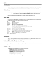
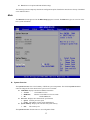
EverServ Series 6000 USERS GUIDE Copyright ParTech Inc. PN770501016 PAR warrants its products to be free of manufacturing defects. Please refer to the back of the sales contract for warranty terms and conditions. This document may contain technical or typographical errors. PAR reserves the right to change the document or the product it describes at any time. 2 INTRODUCTION ............................................................................................................................................ 4 GLOSSARY OF TERMS 4 EQUIPMENT DESCRIPTION ........................................................................................................................ 5 POS REGISTER 5 CONNECTOR WELLS 7 PEDESTAL CONNECTOR WELLS 9 SPECIFICATIONS......................................................................................................................................... 10 FEATURES 10 BIOS ............................................................................................................................................................... 12 Introduction 12 Starting Setup.......................................................................................................................................... 12 Using Setup............................................................................................................................................. 12 Getting Help............................................................................................................................................ 12 Unable to Reboot after Configuration Changes...................................................................................... 12 BIOS Menu Bar ...................................................................................................................................... 12 Main 13 Advanced 14 CPU Configuration ................................................................................................................................. 15 IDE Configuration .................................................................................................................................. 16 Super IO Configuration........................................................................................................................... 21 Hardware Health Configuration.............................................................................................................. 23 ACPI Configuration ................................................................................................................................ 24 APM Configuration ................................................................................................................................ 25 Event Log Configuration ........................................................................................................................ 26 MPS Configuration ................................................................................................................................. 27 USB Configuration ................................................................................................................................. 28 PCI/PnP 30 Boot 32 Boot Settings Configuration ................................................................................................................... 33 Boot Device Priority ............................................................................................................................... 35 Hard Disk Drives .................................................................................................................................... 35 Security Settings 36 Chipset 37 North Bridge Configuration.................................................................................................................... 38 SouthBridge Configuration..................................................................................................................... 39 Exit 40 ENERGY STAR ............................................................................................................................................. 41 QUALIFIED COMPUTERS OVERVIEW 41 ENERGY STAR POWER MANAGEMENT 41 ENERGY STAR COMPLIANCE 41 APPENDIX A................................................................................................................................................. 42 Europe – EU Declaration of Conformity 43 3 INTRODUCTION This guide provides information about the EverServ System. It is presented in five parts as outlined in the table below. Introduction Register cabling diagram, sample system configurations. Equipment Description Specifications, a detailed description of each system components. Setup Connect cables to register. Turn On/Off Turning on/off EverServ register. BIOS Provides information on BIOS configurations. GLOSSARY OF TERMS ♦ LCD – Liquid Crystal Display ♦ VGA – Video Graphics Array ♦ EFT – Electronic Funds Transfer ♦ LAN – Local Area Network ♦ DDR – Double Date Rate ♦ KVS- Kitchen Video System ♦ POS – Point of Sale ♦ BIOS – Basic Input Output System ♦ PCI – Peripheral Component Interconnect ♦ PnP – Plug and Play ♦ IDE – Integrated/Intelligent Drive Electronics ♦ ACPI – Advanced Configuration and Power Interface 4 EQUIPMENT DESCRIPTION POS REGISTER Item Description 1. LCD display A screen that shows programming or order information. 2. Power indicator Shows that power is present. 3. Magnetic card reader Accepts employee keycards. Provides access to functions. Not present on all registers. 4. Biometric Reader Permits access to terminal through fingerprint recognition. 5. I-Button RFID tag reader. 2 1 3 5 4 Front View 5 6. Item Description Customer Display Shows the customer the order total, tax total, and any change due. It may also show preset advertisement information or messages. Not present on all registers. 6 6 Rear View 6 CONNECTOR WELLS Item Description 1. Audio Jacks Connects to cables from speaker left, speaker right, and headphone. 2. COMM serial port 1 (RS-232-C) Connects to coin dispensers, remote customer displays, remote order displays, EFT devices, printers, and other serial devices. 3. LAN Connects to a LAN cable. 4. Printer Port Connects to the cable from a printer. A Centronics-compatible parallel port. 5. Video Option Connects to other devices like coin dispenser or printers. *The F7527 +24V Powered USB feature is not supported in units which contain the F7820 IO expansion board. Attaching peripherals to both +24V Powered USB ports is not permitted. 6. Status lights Provides troubleshooting information to service personnel. 7. Power Receptacle Connects to the DC power cable. 8. Keyboard receptacle Allows connection of a PC keyboard or mouse. 9. DVI receptacle Digital display connector. 10. Cash Drawer Receptacle Connect to cash drawers. 11. USB Ports Connects to other devices like coin dispenser or printers. 12. COMM Serial Port 2 Connects to coin dispensers, remote customer displays, remote order displays, EFT devices, printers, and other serial devices. 13. 12V Power Provides power for removable head display. *The EverServ 6000 Terminal supports a +12V dc power accessory jack. The EverServ terminal also supports the optional F7820 IO expansion card in the pedestal. The F7820 IO Expansion Card also provides a +12V dc power accessory jack. Use of both power jacks simultaneously is not permitted. 14. Power switch Push in momentarily to turn “on”, push and hold to turn “off”. You can reach it by sliding your hand under the left side of the register toward the back. Leave the kiosk on at all times, except when servicing the unit. 7 2 1 14 13 12 3 11 4 5 6 10 9 8 8 7 PEDESTAL CONNECTOR WELLS Item Description 1. Power Receptacle Connects to power cable. 2. KVS Receptacle Connects to KVS cable. 3. USB 24V @ 2A Connects to powered USB devices. 4. USB 12V @ 2A Connects to powered USB devices. 5. COM5 Connects to various serial devices. 6. COM6 Connects to various serial devices. 7. USB Connects to other USB devices. 8. 12V DC @ 2A Connects to DC power cable. *The EverServ 6000 Terminal supports a +12V dc power accessory jack. The EverServ terminal also supports the optional F7820 IO expansion card in the pedestal. The F7820 IO Expansion Card also provides a +12V dc power accessory jack. Use of both power jacks simultaneously is not permitted. 3 2 4 5 1 7 8 9 6 SPECIFICATIONS FEATURES Description Part Number PROCESSORS: 1.73 GHz Celeron M 2.0 GHz Core Duo 2.16 GHz Core 2 Duo F7110 F7111 F7112 MEMORY: 512 MB DDR SDRAM 1 GB DDR SDRAM 2 GB DDR SDRAM F7202 F7203 F7204 MAGNETIC STRIP READERS: Blank Cover Plate 2-Track Swipe Reader – OPOS 3-Track Swipe Reader (USB) 3-Track Swipe Reader (RS232) 3-Track Swipe Reader (PS2) F7300 F7302 F7303 F7303-01 F7303-02 PROGRAM/DATA STORAGE: 80 GB 2.5” SATA HDD 8 GB Compact Flash (CF) Card 2 GB SD Memory Card 4 GB SD Memory Card RAID Support 512 KB Battery Backed SRAM F7401 F7410 F7415 F7416 F7420 F7500 MISCELLANEOUS OPTIONS: COM4 with RJ45 Interface +24V Powered USB Integrated Stereo Speakers Mini-PCI WiFi Card Bluetooth Card Fingerprint Sensor I-Button Reader Access Panel 4 Line x 20 Character VFD International (Double Byte) VFD F7520 F7525 F7540 F7550 F7551 F7560 F7570 F7610 F7611 F7613 I/O PORT EXPANSION CARD OPTIONS (F7820): Set COM 5 Configured for +5V Set COM 5 Configured for +12V Set COM 6 Configured for +5V Set COM 6 Configured for +12V Pedestal Top Cover Pedestal 4 Line x 20 Character VFD Pedestal Int’l VFD (Double Byte) Pedestal 3 Track MSR (USB) Pedestal 3 Track MSR (RS232) Crew Side Pedestal Panel (Blank) F7805-5 F7805-12 F7806-5 F7806-12 F7860 F7861 F7863 F7866 F7866-01 F7870 10 Crew Side Pedestal - Optical Finger Print Customer Side Panel (Opaque) Point of Promotion Lens (Clear) Graphics LCD w/Touch Screen Graphics LCD w/o Touch Screen F7871 F7880 F7881 F7882 F7883 CASH DRAWER PARTS: Cash drawer lock Cash drawer springs Shock dampers F1500 980000501 980000540 11 BIOS Introduction This user manual describes the AMI BIOS setup program and configuration options of the EverServ motherboard. The BIOS setup program allows users to modify the basic system configuration of the EverServ motherboard. Starting Setup The AMI BIOS is activated when the computer is turned on. The setup program can be activated in one of two ways. 1. Press the DELETE key as soon as the system is turned on or 2. Press the DELETE key when the “Press Del to enter SETUP” message appears on the screen. 0. If the message disappears before the DELETE key is pressed, restart the computer and try again. Using Setup Use the arrow keys to highlight items, press ENTER to select, use the PageUp and PageDown keys to change entries, press F1 for help and press ESC to quit. Navigation keys are shown in. Key Function Up arrow Down arrow Left arrow Right arrow Esc key Move to previous item Move to next item Move to the item on the left hand side Move to the item on the right hand side Main Menu – Quit and not save changes into CMOS Status Page Setup Menu and Option Page Setup Menu -- Exit current page and return to Main Menu Page Up key Increase the numeric value or make changes Page Dn key Decrease the numeric value or make changes F1 key General help, only for Status Page Setup Menu and Option Page Setup Menu F2 /F3 key Change color from total 16 colors. F2 to select color forward. F10 key Save all the CMOS changes, only for Main Menu Table 1-1: BIOS Navigation Keys Getting Help When F1 is pressed a small help window describing the appropriate keys to use and the possible selections for the highlighted item appears. To exit the Help Window press ESC or the F1 key again. Unable to Reboot after Configuration Changes If the computer cannot boot after changes to the system configuration is made, CMOS defaults. Use the clear CMOS jumper described in the motherboard user manual. BIOS Menu Bar The menu bar on top of the BIOS screen has the following main items: Main Changes the basic system configuration. Advanced Changes the advanced system settings. PCIPnP Changes the advanced PCI/PnP Settings Boot Changes the system boot configuration. Security Changes the security settings. Chipset Changes the chipset settings. 12 Exit Selects exit options and loads default settings The following sections completely describe the configuration options found in the menu items at the top of the BIOS screen and listed above. Main The Main BIOS menu appears when the BIOS Setup program is entered. The Main menu gives an overview of the basic system information. BIOS Menu 1: Main Î System Overview The System Overview lists a brief summary of different system components. The fields in System Overview cannot be changed. The items shown in the system overview include: AMI BIOS: Displays auto-detected BIOS information o Version: Current BIOS version o Build Date: Date the current BIOS version was made o ID: Installed BIOS ID Processor: Displays auto-detected CPU specifications o Speed: Lists the processor speed o Count: The number of CPUs on the motherboard System Memory: Displays the auto-detected system memory. o Size: Lists memory size The System Overview field also has two user configurable fields: 13 Î System Time [xx:xx:xx] Î Use the System Time option to set the system time. Manually enter the hours, minutes and seconds. System Date [xx/xx/xx] Use the System Date option to set the system date. Manually enter the day, month and year. Advanced Use the Advanced menu to configure the CPU and peripheral devices through the following sub-menus: WARNING: Setting the wrong values in the sections below may cause the system to malfunction. Make sure that the settings made are compatible with the hardware. CPU Configuration IDE Configuration SuperIO Configuration Hardware Health Configuration ACPI Configuration APM Configuration Event Log Configuration MPS Configuration USB Configuration BIOS Menu 2: Advanced 14 CPU Configuration Use the CPU Configuration menu to view detailed CPU specifications and configure the CPU. BIOS Menu 3: CPU Configuration The CPU Configuration menu (BIOS Menu 3) lists the following CPU details: Manufacturer: Lists the name of the CPU manufacturer Brand String: Lists the brand name of the CPU being used Frequency: Lists the CPU processing speed FSB Speed: Lists the FSB speed Cache L1: Lists the CPU L1 cache size Cache L2: Lists the CPU L2 cache size The following CPU Configuration menu item can be configured. Intel ® SpeedStep ™ tech. Î Intel (R) SpeedStep (tm) tech. [Maximum Speed] Use the Intel (R) SpeedStep (tm) tech. option to set the CPU speed. Î CPU speed is set to maximum Maximum Speed DEFAULT Î Minimum Speed CPU speed is set to minimum Î Automatic CPU speed is set to automatic Î Disabled CPU speed is disabled 15 IDE Configuration Use the IDE Configuration menu to change and/or set the configuration of the IDE devices installed in the system. BIOS Menu 4: IDE Configuration 16 IDE Master, IDE Slave Use the IDE Master and IDE Slave configuration menu to view both primary and secondary IDE device details and configure the IDE devices connected to the system. BIOS Menu 5: IDE Master and IDE Slave Configuration 17 Auto-Detected Drive Parameters Î The “grayed-out” items in the left frame are IDE disk drive parameters automatically detected from the firmware of the selected IDE disk drive. The drive parameters are listed as follows: Device: Lists the device type (e.g. hard disk, CD-ROM etc.) Type: Indicates the type of devices a user can manually select Vendor: Lists the device manufacturer Size: List the storage capacity of the device. LBA Mode: Indicates whether the LBA (Logical Block Addressing) is a method of addressing data on a disk drive is supported or not. Block Mode: Block mode boosts IDE drive performance by increasing the amount of data transferred. Only 512 bytes of data can be transferred per interrupt if block mode is not used. Block mode allows transfers of up to 64 KB per interrupt. PIO Mode: Indicates the PIO mode of the installed device. Async DMA: Indicates the highest Asynchronous DMA Mode that is supported. Ultra DMA: Indicates the highest Synchronous DMA Mode that is supported. S.M.A.R.T.: Indicates whether or not the Self-Monitoring Analysis and Reporting Technology protocol is supported. 32Bit Data Transfer: Enables 32-bit data transfer. Type [Auto] Use the Type BIOS option select the type of device the AMIBIOS attempts to boot from after the Power-On SelfTest (POST) is complete. Î BIOS is prevented from searching for an IDE disk drive on Not Installed the specified channel. Î Auto Î CD/DVD The CD/DVD option specifies that an IDE CD-ROM drive is attached to the specified IDE channel. The BIOS does not attempt to search for other types of IDE disk drives on the specified channel. Î ARMD This option specifies an ATAPI Removable Media Device. These include, but are not limited to: DEFAULT The BIOS auto detects the IDE disk drive type attached to the specified channel. This setting should be used if an IDE hard disk drive is attached to the specified channel. Î Î Î ZIP LS-120 LBA/Large Mode [Auto] Use the LBA/Large Mode option to disable or enable BIOS to auto detects LBA (Logical Block Addressing). LBA is a method of addressing data on a disk drive. In LBA mode, the maximum drive capacity is 137 GB. Î BIOS is prevented from using the LBA mode control on the Disabled specified channel. Î Î Auto DEFAULT BIOS auto detects the LBA mode control on the specified channel. Block (Multi Sector Transfer) [Auto] Use the Block (Multi Sector Transfer) to disable or enable BIOS to auto detect if the device supports multi-sector transfers. 18 Î Î Disabled Î Auto BIOS is prevented from using Multi-Sector Transfer on the specified channel. The data to and from the device occurs one sector at a time. DEFAULT BIOS auto detects Multi-Sector Transfer support on the drive on the specified channel. If supported the data transfer to and from the device occurs multiple sectors at a time. PIO Mode [Auto] Use the PIO Mode option to select the IDE PIO (Programmable I/O) mode program timing cycles between the IDE drive and the programmable IDE controller. As the PIO mode increases, the cycle time decreases. Î Auto DEFAULT BIOS auto detects the PIO mode. Use this value if the IDE disk drive support cannot be determined. Î 0 PIO mode 0 selected with a maximum transfer rate of 3.3MBps Î 1 PIO mode 1 selected with a maximum transfer rate of 5.2MBps Î 2 PIO mode 2 selected with a maximum transfer rate of 8.3MBps Î 3 PIO mode 3 selected with a maximum transfer rate of 11.1MBps Î 4 PIO mode 4 selected with a maximum transfer rate of 16.6MBps (This setting generally works with all hard disk drives manufactured after 1999. For other disk drives, such as IDE CD-ROM drives, check the specifications of the drive.) Î DMA Mode [Auto] Î Use the DMA Mode BIOS selection to adjust the DMA mode options. Auto DEFAULT BIOS auto detects the DMA mode. Use this value if the IDE disk drive support cannot be determined. Î SWDMA0 Single Word DMA mode 0 selected with a maximum data transfer rate of 2.1MBps Î SWDMA1 Single Word DMA mode 1 selected with a maximum data transfer rate of 4.2MBps Î SWDMA2 Single Word DMA mode 2 selected with a maximum data transfer rate of 8.3MBps Î MWDMA0 Multi Word DMA mode 0 selected with a maximum data transfer rate of 4.2MBps Î MWDMA1 Multi Word DMA mode 1 selected with a maximum data transfer rate of 13.3MBps Î MWDMA2 Multi Word DMA mode 2 selected with a maximum data transfer rate of 16.6MBps Î UDMA1 Ultra DMA mode 0 selected with a maximum data transfer rate of 16.6MBps Î UDMA1 Ultra DMA mode 1 selected with a maximum data transfer rate of 25MBps Î UDMA2 Ultra DMA mode 2 selected with a maximum data transfer rate 19 of 33.3MBps Î Î UDMA3 Ultra DMA mode 3 selected with a maximum data transfer rate of 44MBps (To use this mode, it is required that an 80-conductor ATA cable is used.) Î UDMA4 Ultra DMA mode 4 selected with a maximum data transfer rate of 66.6MBps (To use this mode, it is required that an 80conductor ATA cable is used.) Î UDMA5 Ultra DMA mode 5 selected with a maximum data transfer rate of 99.9MBps (To use this mode, it is required that an 80conductor ATA cable is used.) S.M.A.R.T [Disabled] Use the S.M.A.R.T option to auto-detect, disable or enable Self-Monitoring Analysis and Reporting Technology (SMART) on the drive on the specified channel. S.M.A.R.T predicts impending drive failures. The S.M.A.R.T BIOS option enables or disables this function. Î BIOS auto detects HDD SMART support. Auto Î Î Disabled Î Enabled DEFAULT Prevents BIOS from using the HDD SMART feature. Allows BIOS to use the HDD SMART feature 32Bit Data Transfer [Enabled] Î Î Use the 32Bit Data Transfer BIOS option to enables or disable 32-bit data transfers. Prevents the BIOS from using 32-bit data transfers. Disabled Enabled DEFAULT Allows BIOS to use 32-bit data transfers on supported hard disk drives. 20 Super IO Configuration Use the Super IO Configuration menu to set or change the configurations for the FDD controllers, parallel ports and serial ports. BIOS Menu 6: Super IO Configuration Î Serial Port1 Address [3F8/IRQ4] Î Î Use the Serial Port1 Address option to select the Serial Port 1 base address. No base address is assigned to Serial Port 1 Disabled Î 3F8/IRQ4 Î 3E8/IRQ4 Serial Port 1 I/O port address is 3E8 and the interrupt address is IRQ4 Î 2E8/IRQ3 Serial Port 1 I/O port address is 2E8 and the interrupt address is IRQ3 DEFAULT Serial Port 1 I/O port address is 3F8 and the interrupt address is IRQ4 Serial Port2 Address [2F8/IRQ3] Î Î Use the Serial Port2 Address option to select the Serial Port 2 base address. No base address is assigned to Serial Port 2 Disabled 2F8/IRQ3 DEFAULT Serial Port 2 I/O port address is 3F8 and the interrupt address is IRQ3 21 Î Î 3E8/IRQ4 Serial Port 2 I/O port address is 3E8 and the interrupt address is IRQ4 Î 2E8/IRQ3 Serial Port 2 I/O port address is 2E8 and the interrupt address is IRQ3 Parallel Port Address [378] Î Î Use the Parallel Port Address option to select the parallel port base address. No base address is assigned to the Parallel Port Disabled Î 378 Î 278 Parallel Port I/O port address is 278 Î 3BC Parallel Port I/O port address is 3BC Parallel Port I/O port address is 378 DEFAULT Parallel Port Mode [EPP] Î Use the Parallel Port Mode option to select the mode the parallel port operates in. The normal parallel port mode is the standard mode for Normal parallel port operation. Î EPP Î ECP The parallel port operates in the extended capabilities port (ECP) mode. The ECP mode supports bi-directional communication between the system and the parallel port device and the transmission rates between the two are much faster than the Normal mode. Î ECP+EPP The parallel port operates in the extended capabilities port (ECP) mode. The ECP mode supports bi-directional communication between the system and the parallel port device and the transmission rates between the two are much faster than the Normal mode DEFAULT The parallel port operates in the enhanced parallel port mode (EPP). The EPP mode supports bi-directional communication between the system and the parallel port device and the transmission rates between the two are much faster than the Normal mode. The parallel port is also be compatible with EPP devices described above Î Parallel Port IRQ [IRQ7] Î Î Î Use the Parallel Port IRQ selection to set the parallel port interrupt address. IRQ5 is assigned as the parallel port interrupt address IRQ5 IRQ7 DEFAULT IRQ7 is assigned as the parallel port interrupt address Serial Port3 Address [3E8/IRQ5] Î Î Use the Serial Port3 Address option to select the base addresses for serial port 3 No base address is assigned to serial port 3 Disabled 3E8/IRQ5 DEFAULT Serial port 3 I/O port address is 3E8 22 Hardware Health Configuration The Hardware Health Configuration menu shows the operating temperature, fan speeds and system voltages. BIOS Menu 7: Hardware Health Configuration The following system parameters and values are shown. The system parameters that are monitored are: System Temperatures: The following system temperatures are monitored o System Temperature 1 o System Temperature 2 o CPU Temperature Fan Speeds: The CPU cooling fan speed is monitored. o Fan1 Speed o Fan2 Speed Voltages: The following system voltages are monitored o CPU Core o +3.30V o +5.00V o +12V o +1.5V 23 ACPI Configuration The ACPI Configuration menu configures the Advanced Configuration and Power Interface (ACPI) and Power Management (APM) options. BIOS Menu 8: ACPI Configuration Î ACPI Aware O/S [Yes] Use the ACPI Aware O/S option to enable the system to configure ACPI power saving options. ACPI can only be implemented if the system OS complies with the ACPI standard. Windows 98, Windows 2000, and Windows XP all comply with ACPI. Î Disables the ACPI support for the OS. This selection should be No disabled if the OS does not support ACPI Î Î Yes DEFAULT Enables the ACPI support for the operating system. This selection should be enabled if the OS does support ACPI Suspend Mode [S3 (STR)] 24 APM Configuration The APM Configuration menu configures the Advanced Power Management (APM) options. 25 Event Log Configuration Use the Event Log Configuration menu to view or delete the system event log storing POSt and run-time errors and events. BIOS Menu 9: Event Log Configuration Î View Event Log Enable the View Event Log option to view all unread event entries in a display window. Î Mark all event as read Enable the View Event Log option to mark all unread events as read. Î Clear Event Log Enable the View Event Log option to discard all events in the Event Log. 26 MPS Configuration Use the MPS Configuration menu to select the multi-processor table. BIOS Menu 10: MPS Configuration Î MPS Function [Enabled] Î Î Î Use the MPS Function option to enable or disable the MPS function. MPS function is enabled. Disabled Enabled DEFAULT MPS function is disabled. MPS Revision [1.4] Î Î Use the Multiprocessor Specification (MPS) for OS option to specify the MPS version to be used. MPS version 1.1 is used 1.1 1.4 DEFAULT MPS version 1.4 is used 27 USB Configuration Use the USB Configuration menu to read USB configuration information and configure the USB settings. BIOS Menu 11: USB Configuration Î USB Configuration Î The USB Configuration field shows the system USB configuration. The items listed are: Module Version: x.xxxxx.xxxxx USB Devices Enabled Î The USB Devices Enabled field lists the USB devices that are enabled on the system USB Function [4 USB Ports] Use the USB Function BIOS option to enable or disable a specified number of USB ports. If only two USB ports are being used, disabling the remaining six USB frees up system resources that can be redirected elsewehere. 28 Î Legacy USB Support [Enabled] The Legacy USB Support BIOS option refers to USB mouse and USB keyboard support. Normally if this option is not enabled, any attached USB mouse or USB keyboard does not become available until a USB compatible operating system is fully booted with all USB drivers loaded. When this option is enabled, any attached USB mouse or USB keyboard can control the system even when there is no USB driver loaded on the system. Î Legacy USB support disabled Disabled Î Î DEFAULT Legacy USB support enabled USB 2.0 Controller [Enabled] Î Î Î Enabled Use the USB 2.0 Controller BIOS option to enable or disable the USB 2.0 controller USB 2.0 controller disabled Disabled Enabled DEFAULT USB 2.0 controller enabled USB2.0 Controller Mode [HiSpeed] Î Î Use the USB2.0 Controller Mode option to set the speed of the USB2.0 controller. The controller is capable of operating at 12Mb/s FullSpeed HiSpeed DEFAULT The controller is capable of operating at 480Mb/s 29 PCI/PnP Use the PCI/PnP menu to configure advanced PCI and PnP settings. WARNING! Setting wrong values for the BIOS selections in the PCIPnP BIOS menu may cause the system to malfunction. BIOS Menu 12: PCI/PnP Configuration Î Clear NVRAM [No] Use the Clear NVRAM option to specify if the NVRAM (Non-Volatile RAM) is cleared when the power is turned off. Î No DEFAULT System does not clear NVRAM during system boot Î Î Yes System clears NVRAM during system boot Plug & Play O/S [No] Use the Plug & Play O/S BIOS option to specify whether system plug and play devices are configured by the operating system or the BIOS. Î No DEFAULT If the operating system does not meet the Plug and Play specifications, this option allows the BIOS to configure all the devices in the system. 30 Î Î This setting allows the operating system to change the interrupt, I/O, and DMA settings. Set this option if the system is running Plug and Play aware operating systems. IRQ# [Available] Î Î Î Yes Use the IRQ# address to specify what IRQs can be assigned to a particular peripheral device. The specified IRQ is available to be used by PCI/PnP Available DEFAULT devices Reserved The specified IRQ is reserved for use by Legacy ISA devices Available IRQ addresses are: IRQ3 IRQ4 IRQ5 IRQ7 IRQ9 IRQ10 IRQ 11 IRQ 14 IRQ 15 DMA Channel# [Available] Î Î Use the DMA Channel# option to assign a specific DMA channel to a particular PCI/PnP device. The specified DMA is available to be used by PCI/PnP Available DEFAULT devices Reserved The specified DMA is reserved for use by Legacy ISA devices Available DMA Channels are: DM Channel 0 DM Channel 1 DM Channel 3 DM Channel 5 DM Channel 6 DM Channel 7 31 Boot Use the Boot menu to configure system boot options. BIOS Menu 13: Boot 32 Boot Settings Configuration Use the Boot Settings Configuration menu to configure advanced system boot options. BIOS Menu 14: Boot Settings Configuration Î Quick Boot [Enabled] Î Î Î Enabled DEFAULT Some POST procedures are skipped to decrease the system boot time Quiet Boot [Disabled] Î Î Î Use the Quick Boot BIOS option to make the computer speed up the boot process. No POST procedures are skipped Disabled Use the Quiet Boot BIOS option to select the screen display when the system boots. Normal POST messages displayed Disabled DEFAULT Enabled OEM Logo displayed instead of POST messages AddOn ROM Display Mode [Force BIOS] Î Î Use the AddOn ROM Display Mode option to allow add-on ROM (read-only memory) messages to be displayed. Force BIOS DEFAULT The system forces third party BIOS to display during system boot. Keep Current The system displays normal information during system boot. 33 Î Bootup Num-Lock [On] Use the Bootup Num-Lock BIOS option to specify if the number lock setting must be modified during boot up. Î Off Î On Does not enable the keyboard Number Lock automatically. To use the 10-keys on the keyboard, press the Number Lock key located on the upper left-hand corner of the 10-key pad. The Number Lock LED on the keyboard lights up when the Number Lock is engaged. DEFAULT Allows the Number Lock on the keyboard to be enabled automatically when the computer system boots up. This allows the immediate use of the 10-key numeric keypad located on the right side of the keyboard. To confirm this, the Number Lock LED light on the keyboard is lit. 34 Boot Device Priority Use the Boot Device Priority menu to specify the boot sequence from the available devices. Possible boot devices may include: 1st FLOPPY DRIVE HDD CD/DVD PAR NETWORK BOOT Hard Disk Drives Use the Hard Disk Drives menu to specify the boot sequence of the available HDDs. When the menu is opened, the HDDs connected to the system are listed as shown below: 1st Drive [HDD: PM-(part number)] 2nd Drive [HDD: PS-(part number)] NOTE: Only the drives connected to the system are shown. For example, if only two HDDs are connected only “1st Drive” and “2nd Drive” are listed. The boot sequence from the available devices is selected. If the “1st Drive” option is selected a list of available HDDs is shown. Select the first HDD the system boots from. If the “1st Drive” is not used for booting this option may be disabled. 35 Security Settings Use the Security Settings menu to set passwords for supervisor/user. Î Supervisor Password [Not Installed] Î User Password [Not Installed] Î Change Supervisor Password Use the Change Supervisor Password option to change the supervisor password. Î Change User Password Use the Change User Password option to change the user password. Î Clear User Password Use the Clear User Password option to clear the user password. 36 Chipset Use the Chipset menu to access the North Bridge and South Bridge configuration menu. WARNING! Setting the wrong values for the Chipset BIOS selections in the Chipset BIOS menu may cause the system to malfunction. BIOS Menu 15: Chipset 37 North Bridge Configuration Use the North Bridge Configuration menu to configure the North Bridge chipset. BIOS Menu 16:NorthBridge Chipset Configuration Î Boot Graphic Adapter Priority [PEG/PCI ] The Boot Graphic Adapter Priority option selects the graphics controller the system uses as a primary boot device. Î Internal Graphics Mode Select [Enable, 8MB] Use the Internal Graphic Mode Select option to specify the amount of system memory that can be used by the Internal graphics device. Î Disable Î Enable, 1MB 1MB of memory used by internal graphics device Î Enable, 4MB 4MB of memory used by internal graphics device Î Enable, 8MB Î Enable, 16MB 16MB of memory used by internal graphics device Î Enable, 32MB 32MB of memory used by internal graphics device DEFAULT 8MB of memory used by internal graphics device 38 Video Function Configuration Use the Video Function Configuration menu to configure the video device connected to the system. SouthBridge Configuration Use the SouthBridge Configuration menu to configure the South Bridge chipset. 39 Exit Use the Exit menu to load default BIOS values, optimal failsafe values and to save configuration changes. BIOS Menu 17:Exit Î Save Changes and Exit Î Use the Save Changes and Exit option to save the changes made to the BIOS options and to exit the BIOS configuration setup program. Discard Changes and Exit Î Use the Discard Changes and Exit option to exit the BIOS configuration setup program without saving the changes made to the system. Discard Changes Î Use the Discard Changes option to discard the changes and remain in the BIOS configuration setup program. Load Optimal Defaults Î Use the Load Optimal Defaults option to load the optimal default values for each of the parameters on the Setup menus. F9 key can be used for this operation. Load Failsafe Defaults 40 ENERGY STAR QUALIFIED COMPUTERS OVERVIEW ♦ Depending on usage, an ENERGY STAR qualified computer will use up to 50% less energy. ♦ Your office can save up to $90 per monitor per year by enabling computer and monitor’s ENERGY STAR power management features. ♦ $1 billion annually in energy costs would be saved if every desktop and monitor in U.S. was set to sleep when not in use; while avoiding greenhouse gases comparable to emissions of 1 million cars. ENERGY STAR POWER MANAGEMENT: ♦ ♦ ♦ ENERGY STAR power management features: o Standard in all Windows and Macintosh operating systems. o After periods of inactivity places computers and monitors into low-power mode. To maximize savings EPA recommends: o Standby mode after 30-60 minutes of inactivity. o Sleep after 5-20 minutes of inactivity. By activating ENERGY STAR power management features you can quickly and easily save energy, money, and help protect your environment. ENERGY STAR COMPLIANCE: Certain configurations of EverServ6000 Systems meet the terms with the requirements set by the Environmental Protection Agency (EPA) for energy-efficient computers. If the front of your system shows the ENERGY STAR logo, the system is configured and meets with the requirements; ENERGY STAR power management features are automatically enabled. NOTE: If your EverServ has the ENERGY STAR logo It has been determined by PAR, as an ENERGY STAR partner, that your system complies with the ENERGY STAR guidelines for energy efficiency. NOTE: When shipped all PAR systems showing the ENERGY STAR logo are certified to meet with EPA ENERGY STAR requirements. Changes made to your system configuration may increase power usage beyond limits set by EPA’s ENERGY STAR Computers program. ENERGY STAR Logo: The EPA’s ENERGY STAR Computers program, with the joint effort of computer manufacturers and the Environmental Protection Agency, aims to reduce air pollution by encouraging energy-efficient computer systems. ENERGY STAR computer product usage is estimated by the EPA to save computer users up to two billion dollars a year in electricity. This reduces the emissions of carbon dioxide, the gas primarily responsible for the greenhouse effect, and sulfur dioxide and nitrogen oxides, which are the primary causes of acid rain. As a user you can help reduce the electricity use including its side effects by shutting down your computer when it is not in use, nights and weekends. 41 APPENDIX A Separating PPC from POS 1. Loosen the (2) thumbscrews under the Panel POS (operator side) which secure the cover over the main board IO connectors – remove cover. 2. Loosen the (2) thumbscrews under the pedestal which secure the (operator side) pedestal cover – remove cover. 3. Loosen the (2) thumbscrews under the pedestal which secure the side panels of the pedestal – remove side panels. 4. Loosen the (2) thumbscrews under the panel POS which secure the cable clamp which holds any peripheral cables attached to the main board. 5. Loosen the (2) thumbscrews on the operator side of the pedestal which secure the cable clamp as in step 4 above. 6. Remove any peripheral IO cables attached to the main board IO ports. 7. Loosen the (2) thumbscrews under the pedestal which secure the (customer side) pedestal cover – remove cover. 8. Loosen the thumbscrew on the pedestal side which secures the AC power cord to the power brick. 9. Disconnect AC power cord from the power brick. 10. Disconnect any cables to the IO board in the pedestal. 11. Loosen the thumbscrew on customer side of the pedestal which secures the power supply retaining bracket – remove bracket. 12. Remove the power supply. 13. Using a Philips screwdriver – remove the (2) screws at the top of the Panel POS on the customer side which secure the cover on the back side of the Panel POS – slide up and remove the back cover. 14. Disconnect the IO cable from the back side of the main board. 15. Disconnect the SATA cable from the back side of the main board. 16. Tilt the display assembly back and remove the (2) thumbscrews securing the Panel POS to the pedestal mount. 17. Tilt the display forward – slide panel POS straight up to remove. 18. Install the replacement Panel POS back cover (customer side). 42 Europe – EU Declaration of Conformity This device complies with the essential requirements of the R&TTE Directive 1999/5/EC. The following test methods have been applied in order to prove presumption of conformity with the essential requirements of the R&TTE Directive 1999/5/EC: - EN 60950-1: 2001 Safety of Information Technology Equipment - EN50371 : (2002-03) Generic standard to demonstrate the compliance of low power electronic and electrical apparatus with the basic restrictions related to human exposure to electromagnetic fields (10 MHz - 300 GHz) -- General public - EN62311 : 2008 Generic standard to demonstrate the compliance of electronic and electrical apparatus with the basic restrictions related to human exposure to electromagnetic fields (0 Hz - 300 GHz) - EN 300 328 V1.7.1: (2006-10) Electromagnetic compatibility and Radio spectrum Matters (ERM); Wideband Transmission systems; Data transmission equipment operating in the 2,4 GHz ISM band and using spread spectrum modulation techniques; Harmonized EN covering essential requirements under article 3.2 of the R&TTE Directive - EN 301 893 V1.4.1: (2007-07) Broadband Radio Access Networks (BRAN); 5 GHz high performance RLAN; Harmonized EN covering essential requirements of article 3.2 of the R&TTE Directive EN 301 489-1 V1.6.1: (2005-09) Electromagnetic compatibility and Radio Spectrum Matters (ERM); ElectroMagnetic Compatibility (EMC) standard for radio equipment and services; Part 1: Common technical requirements - EN 301 489-17 V1.2.1 (2002-08) Electromagnetic compatibility and Radio spectrum Matters (ERM); ElectroMagnetic Compatibility (EMC) standard for radio equipment and services; Part 17: Specific conditions for 2,4 GHz wideband transmission systems and 5 GHz high performance RLAN equipment This device is a 2.4 GHz wideband transmission system (transceiver), intended for use in all EU member states and EFTA countries, except in France and Italy where restrictive use applies. In Italy the end-user should apply for a license at the national spectrum authorities in order to obtain authorization to use the device for setting up outdoor radio links and/or for supplying public access to telecommunications and/or network services. This device may not be used for setting up outdoor radio links in France and in some areas the RF output power may be limited to 10 mW EIRP in the frequency range of 2454 – 2483.5 MHz. For detailed information the end-user should contact the national spectrum authority in France. 43 SAFETY ♦ Before connecting cables or devices to connector wells, please turn off the power first thus preventing potential ESD damage. ♦ The service related to human safety is not allowed because this device may have the possibility of the radio interference. ♦ As this equipment has undergone EMC registration for business purpose (“A” class), the seller and/or the buyer is asked to beware of this point and designed to be used in the area, except for home use. 44 PAR PHONE NUMBERS Service USA: 800.382.6200 Canada: 800.387.4963 Parts USA: 800.PAR.PART Canada: 800.387.4963 Sales Continental USA except New York: 800.448.6505 New York State Only: 800.533.6311 Outside Continental USA: 315-738-0600 Driver Support http://www.partech.com/pti_products_services/service_existing_customer.cfm 45