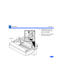
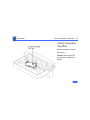
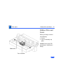
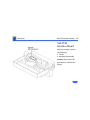
1
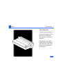
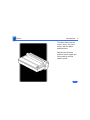
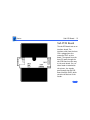
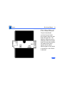
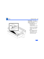
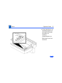
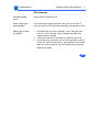
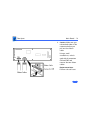
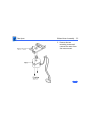
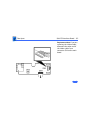
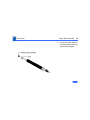
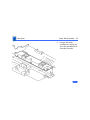
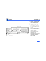
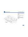
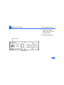
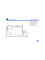
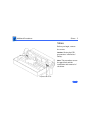
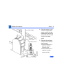
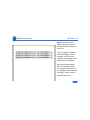
K Service Source
ImageWriter II/L
Basics
Introduction - 1
Introduction
The electrical operation of
the printer consists of five
printed circuit boards,
three motors, and several
switches.
The boards are the power
supply board, main board,
sub PCB board, print head
board, and the operation
panel board.
Basics
Introduction - 2
The three motors are the
carrier motor, line feed
motor, and the ribbon
position motor.
Switches are the home
position switch, paper-out
sensor switch, and the
ribbon switch.
Basics
Power Supply - 3
Power Supply
The ImageWriter II/L has a
switching type power supply
that eliminates the need for
a bulky transformer. When
the input AC current is
applied to this board, the
power supply reduces and
rectifies the voltage to the
following DC voltages:
• + 5 V DC
• – 5 V DC
• + 26 V DC
Basics
Power Supply - 4
The + 5 and –5 V DC voltages
are for logic; the + 26 V DC
is for motor drive. All the
voltages are fed from
connector CN5 on the power
supply board to connector
CN3 on the main board.
From the main board the
voltages are distributed to
the other boards and motors.
Basics
Power Supply - 5
The power supply has two
fuses to help protect the
electronics—FU1 is a 120 V
2-amp fuse and FU2 is a
125 V 4–amp fuse.
Note: Although not on the
power supply board, there
is another fuse, FU1, located
on the main board that
protects the + 26 motor
voltage.
Basics
Power Supply - 6
The on/off power switch is
connected to the power
supply board and disconnects
or connects the main AC
current to the board. The
switch is comprised of a
cable type plunger that is
attached to the power
supply board.
Caution: This power supply
is not compatible with the
older ImageWriter II. Do
not attempt to switch the
power supplies between
models.
Basics
Main Board - 7
Main Board
The main board is the heart
of the printer. Besides
handling the distribution of
the voltages, it also handles
all the logic that controls the
printer. It is also the source
of the drive signals for the
print head. All sensor
signals that affect the
operation of the printer are
fed to this board.
ImageWriter II/L
Basics - 8
ROM
Interface Circuits
The ROM (IC10) chip has the start-up
routines and several features such as
character sets and self-test routines built
in.
The interface circuits (IC2 and IC3) on the
main board handle the data transferred
from the host CPU via the sub PCB board.
These circuits also handle the status and
control lines from the printer to the host
CPU.
RAM
The RAM (IC9) is used in the transfer of
data and acts as a buffer. When printing
starts, the data to be printed is transferred
from the host CPU to the RAM on the
printer. From the RAM the data is passed
through the logic and sent to the print head
to print. Turning off the printer clears the
RAM.
Print Head Drivers
The print head drivers (IC5 and IC6)
process the print head drive signals from
the CPU and gate array. The signals are sent
to the print head board through CN5.
ImageWriter II/L
Basics - 9
CPU and Gate Array
Carrier Motor Drivers
The CPU (IC8) along with the gate array
(IC4), handles the logic and decisionmaking of the printer. They combine to
evaluate the status of the printer and issue
commands concerning when to transfer
data, when to start printing, when to run
the motors, and what actually prints. All
the functions of the printer are controlled
by these two devices. The rest of the
circuits are supporting circuits.
The carrier motor circuit is made up of
transistors Q1, Q2, Q12, Q13 and IC1. The
transistors make up a circuit that is used as
common returns from the motor. The
transistors also supply the higher voltage
and current needed to drive the motor. IC1
is a transistor pack that completes the
drive signals circuit when turned on. Each
of the four signals drives a phase of the
motor. These drive signals go to the carrier
motor on the printer through CN2.
ImageWriter II/L
Basics - 10
Line Feed
Ribbon Motor Drivers
The drive circuit is made up of transistors
Q8, Q9, Q10, and Q11. Four drive signals
from the gate array are processed in this
circuit. Higher voltage and current are
added to the phase control signals to turn on
the line feed motor. The signals are sent to
the line feed motor and the ribbon motor
through CN1.
This circuit is made up of transistors Q3,
Q4, Q5, Q6 and Q7. When turned on, the line
feed motor signals from the gate array are
supplied with more current in the drive
circuit and sent out to the motor. The
common return line is on Q7, which is
turned on for each phase signal sent to the
motor. These signals are sent through CN5.
ImageWriter II/L
Basics - 11
Reset Circuit
Clock Crystals
This circuit is used when the printer is
turned on to keep the logic in a reset state
until the voltages are up to correct values.
Once the voltages are at the correct level,
reset is released and the logic is allowed to
start functioning from a known state.
There are two clock crystals on the main
board. The clock X1 for the gate array IC4
runs at 17.2 MHz. The clock X2 for the CPU
runs at 12 MHz.
Connector CN6
This connector is a LocalTalk option card
connector. This card allows the printer to
communicate on the LocalTalk network so
that multiple users can use the printer.
DIP Switches
The configuration DIP switches are mounted
on the main board and can be changed to
make the printer perform in different
modes, or control printer protocols. The
switch settings affect both the CPU and the
gate array logic.
Basics
Sub PCB Board - 12
Sub PCB Board
The sub PCB board acts as an
interface board. The
interface cable from the host
CPU is plugged into the
connector CNS1 on this
board. The signals from the
host CPU pass through the
sub PCB board on their way
to the main board. If a cutsheet feeder is attached to
the printer, the signals
pass through the sub PCB
board through CNS2, which
controls the actions of the
feeder.
Basics
Sub PCB Board - 13
The paper-out sensor wires
go to this board through
CNS3 and are passed along to
the main board.
All the signals coming or
going to the sub PCB board
are sent through CNS4 and
the ribbon cable to the main
board at connector CN4.
Basics
Print Head Board - 14
Print Head Board
The print head board
receives the print head
drive signals from the main
board through CNH1. The
signals are then sent out on
connector CNH2 to the print
head. This board also handles
the ribbon motor drive
signals and the ribbon
switch signals. If the switch
is activated, a color ribbon
is detected.
Basics
Print Head Board - 15
This information is sent to
the main board, which in
turn sends controlling
signals to the ribbon motor
to control the position of the
ribbon to allow color
printing.
The home position switch
alerts the CPU that the
carriage is at the far left
side of the printer, which is
home position.
Basics
Operation Panel Board - 16
Operation Panel
Board
The operation panel board
has the switches (select,
print quality, line feed, and
form feed) and indicators
(error, power, print
quality, and select) mounted
on it. It interfaces with the
CPU through CN7 on the
main board. While the power
switch button is located on
the operation panel, it is not
connected to the operation
panel board.
Operation Panel
Basics
Operation Panel Board - 17
The switch button just
passes through to the switch
mounted on the main frame
underneath the operation
panel.
Operation Panel
Basics
Operation Panel - 18
Operation Panel
The operation panel consists
of operating switches and
indicator lights.
Indicator
Lights
Operating
Switches
The operating switches are
the buttons with which you
control the printer, and the
indicator lights let you know
what state the printer is in.
Basics
Operation Panel - 19
Operating Switches
Power Switch
Power Switch - The power
switch turns the printer on
and off.
Basics
Operation Panel - 20
Select
Switch
Select Switch - The select
switch toggles the printer
between a selected (online)
and a deselected (off-line)
state. If printing is in
progress when the select
switch is pressed, the
printer finishes printing
the current line and a
maximum of two additional
lines, and stops printing.
Basics
Operation Panel - 21
Select
Switch
If you want to clear the
buffer, you must turn off
the printer. Pressing the
select switch also clears a
corrected error condition.
If an out-of-paper
condition exists, pressing
the select switch
temporarily overrides the
error to allow the print of
one line. This process is
repeatable as long as there
is printable data in the
printer buffer.
Basics
Print
Quality
Operation Panel - 22
Print Quality Switch - The
print quality switch allows
the user to choose one of
three printing modes.
Pressing the print quality
switch repeatedly changes
the mode from the standard
print mode, to the NLQ print
mode, to the draft print
mode, back to the standard
print mode again. The print
quality switch does not
function unless the printer
is in an off-line
(deselected) state.Ê
Basics
Form
Feed
Operation Panel - 23
Form Feed - The form feed
switch does not function
unless the printer is in an
off-line (deselected) state.
When the form feed switch
is pressed, the printer
feeds paper until the next
top of form is reached.
Basics
Form
Feed
Operation Panel - 24
If the switch is pressed and
no paper is present, the
printer assumes a single
sheet is being loaded. The
printer feeds the single
sheet up to the top of form
position. If the switch is
pressed and paper is
present, the printer
monitors the paper-off
switch while feeding paper.
If the printer detects an
out-of-paper condition
before the top of form is
reached, the printer
assumes that single sheets
are being fed.
Basics
Form
Feed
Operation Panel - 25
For the single sheet case,
four inches of paper motion
is added to the form feed to
ensure that the page is
properly ejected.
Basics
Form
Feed
Operation Panel - 26
When an automatic cutsheet feeder is present, the
paper-loading sequence is
slightly different. When the
form feed is pressed with no
paper present, the printer
first rolls the platen to
check if a single sheet had
been inserted. If no paper is
found, the printer loads a
sheet from the automatic
sheet feeder and positions it
at the top-of-form position.
Basics
Operation Panel - 27
Indicators
Select
Power
Power - When lit, the power
light indicates that power is
on.
Select - When the select
indicator is lit, the printer
is online, in a ready state so
that a transmission can take
place.
Basics
Print
Quality
Operation Panel - 28
Print Quality - The print
quality light indicates three
modes of operation:
• NLQ–When both the
left and right
indicators are lit, the
printer is in the Near
Letter Quality print
mode.
• Draft–When just the
left indicator is lit,
the printer is in the
Draft print mode.
Basics
Print
Quality
Operation Panel - 29
• Standard–If the right
indicator is lit, the
printer is in the
Standard print mode.
This is the default
mode when the
printer is turned on.
Basics
Operation Panel - 30
Error
Error - The error light has
three ways of indicating an
error condition in the
printer:
• If the error light comes
on steady and stays on
(and the select light goes
off), the printer is out of
paper.
• If the light blinks in a
steady fashion (evenly
spaced blinks), a cover
is open or a left-margin
error has occurred.
Basics
Operation Panel - 31
Error
• If the light blinks in a
repeating sequence of
one short blink and a
long blink, an
interface
communication or a
RAM check error has
occurred.
K Service Source
Specifications
ImageWriter II/L
Specifications
Characteristics - 1
Characteristics
Print Methods
Throughput
Print Head
Response Time
Draft Mode: 250 characters per second (cps); 25 in. per second
(ips) at 10 characters per in. (cpi)
Standard Mode: 180 cps; 18 ips at 10 cpi
NLQ Mode: 25 cps
100 in. per minute (ipm) at 80 dpi
9 wires
.0139 in. (.353 mm) nominal
Standard:.0118 in. (.300 mm) nominal
Japan:.0098 in. (.250 mm) nominal
1440 Hz
Specifications
Characteristics - 2
Life
Standard: 4 by 108 strokes/wire
Japan:
2 by 108 strokes/wire
Graphics Duty Cycle
25% minimum
Character Sets
Ribbon
ASCII (96 characters)
Six European sets
MouseText (32 characters)
Fabric ribbon
Black or four-color (cannot use color with Kanji print head)
Specifications
I/O Interfaces - 3
I/O Interfaces
Interface
Standard asynchronous
LocalTalk
With option board
Operation
Asynchronous, switch selectable; Data ready/busy (hardware
handshake), or Xon/Xoff serial protocols
Connectors
Mini DIN-8
26-pin male (optional)
Data Format
Asynchronous serial/no parity bit shall be sent
Specifications
I/O Interfaces - 4
Transmission Speed
Switch selectable (300, 1200, 2400, and 9600 baud)
Input Buffer
254K
Specifications
Paper Feed - 5
Paper Feed
Method
Friction feed, adjustable tractors, and automatic single-sheet
loader
Accessories
Automatic, cut-sheet feeder
Direction
Bidirectional (friction feed or tractor feed)
Single sheets, sprocket feed, multicopy (original + three copies),
single-width labels
Type
.002–.011 in. (.05–.28 mm) equivalent to 15–25 lb. bond
Thickness
3.5 in. minimum to “n” in. maximum (“n” is typically 11 or 14
for cut sheets)
Specifications
Electrical - 6
Electrical
Line Voltage
USA/Japan: 85–132 VAC; 48–62 Hz
Europe/Australia: 185–265 VAC; 48–62 Hz
Stand-by:20 W maximum
Operation: 180 W maximum
Specifications
Physical - 7
Physical
Dimensions
Weight
Height: 5 in.
Width: 17 in.
Depth: 12 in.
25 lb. maximum
Specifications
Environmental - 8
Environmental
Temperature
Relative Humidity
Operation:10–40°C
Storage: (one year) –40 to 47°C
Transit: (72 hours) –40 to 65°C
Storage: (six months) 10–95%
K Service Source
Troubleshooting
ImageWriter II/L
Troubleshooting
General/ - 1
General
The Symptom Charts included in this chapter will help you
diagnose specific symptoms related to your product. Because cures
are listed on the charts in the order of most likely solution, try
the first cure first. Verify whether or not the product continues to
exhibit the symptom. If the symptom persists, try the next cure.
(Note: If you have replaced a module, reinstall the original module
before you proceed to the next cure.)
If you are not sure what the problem is, or if the Symptom Charts
do not resolve the problem, refer to the Flowchart for the product
family.
For additional assistance, contact Apple Technical Support.
Troubleshooting
Symptom Charts /Preliminary Check - 2
Symptom Charts
Preliminary Check
Error light blinks
1
2
3
4
Verify that paper cover is secure.
Verify that paper cover magnet is in place.
Try known-good software.
Verify that option card dip switch SW2-4 is open/off with
no card installed.
Select light off, error
light on
1
2
Add paper or reset paper feed tray.
Verify that paper-out sensor works correctly (see Take
Apart).
Select light does come
on
1
2
3
Verify that paper cover is secure.
Verify that paper cover magnet is in place.
Verify that operation cable under top cover is secure.
Troubleshooting
Symptom Charts /Preliminary Check - 3
No printing or
garbled printing
1
Software-specific
problem
Try known-good software.
Prints OK for a while;
then prints garbage
Set DIP switch SW2-3 to correct serial protocol.
Overprinting
Verify that program is set for correct line spacing and line length.
Light printing
1
2
3
2
Check interface cable connection between printer and
computer.
Verify that DIP switches (2-1 through 2-4) are set
correctly.
Change ribbon cartridge.
Adjust impression lever (see Adjustments).
Check for excessive play in carrier assembly. Make sure
assembly is seated correctly (see Take Apart).
Troubleshooting
Symptom Charts/Preliminary Check - 4
Erratic carrier
motion, loud hum
Remove black tube-shaped shipping protection from carrier
shaft.
Printing has
squashed lines;
misregistration
problems with pin
feed paper
1
2
3
4
For best print quality, instruct customer to place stack of
paper behind printer and no more than three feet below
printer. The paper should have a clear, unobstructed entry
and exit path.
Verify that power cord or printer cable does not obstruct
paper path.
Avoid printing in top and bottom one inch of paper (the areas
where squashed line and misregistration problems will be
most apparent).
Use 20-pound paper.
Troubleshooting
Symptom Charts /Print Quality - 5
Print Quality
Compressed first or
second line
1
Print is darker or
lighter on one side
Remove or install shims. See the Shims topic in the Additional
Procedures chapter.
Top row of dots
missing on printout
Perform “Ribbon Adjustment” (refer to Adjustments).
Power light on, no
printing
1
2
2
3
Check position of paper behind printer to ensure there isn’t
anything blocking paper entry or exit.
Replace main board.
Verify that ribbon frame assembly rides on the spiral ridge
on color ribbon cam (see Adjustments).
Remove dot head and verify that pins in the connector on dot
head board are not bent.
Go to “Indicator Lights” (see Flowcharts).
Troubleshooting
Missing dots
Symptom Charts/Print Quality - 6
1
2
3
Check flexible cable connection.
Remove dot head and verify that pins in connector on dot head
board are not bent.
Go to “Printing” (see Flowcharts).
Color self-test does
not work
1
When printing from a
Macintosh, characters
sometimes appear
smudged, or top of
form gradually creeps
down page in one-line
increments
Verify that ImageWriter II/L driver software is the most current
version.
2
Verify that color ribbon detect switch operates and wires are
unbroken. If defective, replace switch.
Top plate of carrier assembly (under ribbon cartridge) is
not properly engaged with color ribbon cam (see Take Apart
or Adjustments).
Troubleshooting
Symptom Charts /Carriage Movement - 7
Carriage Movement
Carriage doesn’t
move; LEDs are not lit
1
2
Replace main board.
Replace power supply board.
Carriage doesn’t
move; LEDs are lit
1
2
Replace main board.
Replace power supply board.
Carriage assembly
moves to the left and
does not return to
center
1
Verify operation of switch on print head board. If switch is
frozen or defective, replace print head board.
Verify that metal tab actuating left-side home position
switch is bent correctly. Use a feeler gauge and bend tab 1
mm toward right side.
Replace main board.
Replace power supply board.
Replace flexible ribbon cable.
2
3
4
5
Troubleshooting
Symptom Charts/Carriage Movement - 8
Carriage moves to the
left and hums very
loudly
1
2
3
Verify that flexible ribbon cable is properly connected to
main board and to its connector under carriage assembly on
print head board.
Replace flexible ribbon cable.
Replace power supply board.
Carriage assembly
grinds or is difficult
to move
1
2
Replace fuse on main board.
Replace power supply board.
Carrier binds on left
side
Paper guide is too close to platen. Readjust paper guide.
Carrier
intermittently locks
up and gives light or
dark print
Verify that rear of carrier assembly does not lift. If it does, it is
not seated correctly in the guide rail. Gently push down on rear of
carrier assembly until it snaps into place.
Troubleshooting
Self-test produces no
carrier movement
(LEDs are lit)
Symptom Charts/Carriage Movement - 9
1
2
3
Remove mechanical assembly to ensure that wires to carrier
motor are not pinched. If wires to carrier motor are worn,
replace them.
Replace fuse on main board.
Replace main board.
Troubleshooting
Symptom Charts/Paper Feed - 10
Paper Feed
Grinding during paper
feed
1
Paper adjustment
lever does not move
Verify that power on/off cable is not pinched between lever and
metal frame or plastic case.
2
3
4
Remove platen knob to verify that there are no obstructions
in the gears beneath knob.
Adjust paper guide (refer to Adjustments).
Replace line feed motor.
Replace main board.
Troubleshooting
Symptom Charts/Miscellaneous - 11
Miscellaneous
Hexadecimal data
prints
Power printer off and then on.
Power supply goes
bad repeatedly
Verify that power supply and motor wires are not pinched. If
wires are pinched, lift mechanical assembly and reposition wires.
Ribbon jams or does
not advance
1
2
3
Check gear box on carrier assembly. Verify that gear with
cross (+) sticks through carrier assembly top plate and
engages ribbon cartridge.
Verify that ribbon wire is properly installed in gear box
Verify that print head wires are not striking platen too hard.
If they are, replace main board. If replacement of main board
does not correct problem, reinstall original main board and
replace print head.
K Service Source
Take Apart
ImageWriter II/L
Take Apart
Covers - 1
Covers
Paper Cover
Ribbon Cover
Top Cover
Ribbon Cartridge
Tractor Cover
No preliminary steps are
required before you begin
this procedure.
Caution: Review the ESD
precautions in Bulletins/
Safety.
Note: This procedure covers
the removal of the top cover,
tractor cover, ribbon cover,
and ribbon cartridge.
Note: To make reassembly
easier, label all cables and
connectors during the takeapart procedure.
Take Apart
Covers - 2
Paper Cover
Ribbon Cover
Paper Cover
Note: The paper cover
assembly must be in place
for the printer to work.
Gently pull the paper cover
up and forward and remove
the cover.
Replacement Note: Remove
the paper cover from the
ribbon cover only if the
paper cover is broken and
needs replacement. Push in
the two tabs and separate the
paper cover from the ribbon
cover.
Take Apart
Covers - 3
Ribbon Cartridge
Tab
Tab
Ribbon Cartridge
Gently pull the tabs apart
and lift the cartridge out.
Take Apart
Covers - 4
Top Cover
Platen
Knob
1
2
3
Captive
Screw
Captive
Screw
Push the carrier
assembly to the far left.
Pull off the platen knob.
Loosen the two captive
screws.
Take Apart
Covers - 5
4
Latch
Top Cover
5
Grasp the top cover on
the left at the part that
goes over the leg.
Release the latch and lift
the cover one inch.
Take Apart
Covers - 6
6
7
8
Gently rotate the cover
toward the front and
turn the cover over.
Using your thumb and
forefinger, unlock
connector CN7 and
remove the ribbon cable.
Lift off the top cover.
Replacement Note:
Perform the self-test.
Connector CN7
Take Apart
Covers - 7
Tractor Cover
Tractor Cover
Gently pull the tractor cover
up and forward until the
cover snaps free.
Take Apart
Operation Panel - 8
Operation Panel
Before you begin, remove
the covers.
Caution: Review the ESD
precautions in Bulletins/
Safety.
Operation Panel
Take Apart
Operation Panel - 9
1
Cable
2
Operation
Panel
Board
Right-
-Left
Top Cover
Remove the three screws
and lift the operation
panel board from the top
cover.
Disconnect the cable
from the operation
panel board.
Take Apart
Operation Panel - 10
3
Power
Switch
Plunger
Note: To make
reinstallation easier,
observe the position of
the power switch
plunger and spring.
Remove the spring and
power switch plunger
from the top cover.
Replacement Note:
Perform the self-test.
See the Additional
Procedures chapter.
Top Cover
Take Apart
Main Board - 11
Main Board
Before you begin, remove
the following:
• Covers
• Option board
Caution: Review the ESD
precautions in Bulletins/
Safety.
Main Board
Take Apart
Main Board - 12
1
Right-
Main Board
Disconnect the three
cable connectors from
the left side of the main
board:
• CN1
• CN2
• CN3
Take Apart
Main Board - 13
2
3
Main Board
Ground Clip
Remove the six screws.
Tilt the front half of the
board up and gently lift
the board partially out.
Replacement Note: Make
sure to replace the
ground clip on the screw
at the lower left of the
board.
Take Apart
Main Board - 14
4
Caution: Make sure you
release both sides of the
connector before you
pull out the ribbon
cable.
Using a small
screwdriver, unlock
each side of connectors
CN4 and CN5 and
remove the two ribbon
cables.
Replacement Note:
Perform the self-test.
Take Apart
Print Head and Paper Guide - 15
Print Head and
Paper Guide
Before you begin, remove
the covers.
Caution: Review the ESD
precautions in Bulletins/
Safety.
Note: The print head does not
have to be removed in order
to remove the paper guide.
Take Apart
Print Head and Paper Guide - 16
Print Head
1
2
Lift the paper bail to its
highest position.
Set the paper thickness
lever to its widest
setting.
Take Apart
Print Head and Paper Guide - 17
3
Gently push and hold
aside the white print
head clamp release
lever and slowly lift the
print head straight out of
the connector.
Replacement Note:
Perform the self-test.
Take Apart
Print Head and Paper Guide - 18
Paper Guide
Remove the two screws and
lift out the paper guide.
Replacement Note: Adjust
the paper guide. See the
Adjustments chapter.
Take Apart
Ribbon Cam Assembly - 19
Ribbon Cam
Assembly
Before you begin, remove
the covers.
Caution: Review the ESD
precautions in Bulletins/
Safety.
Note: There are two versions
of the ribbon cam assembly.
One has a plastic cap and the
other has a hex nut, without
the cap.
Take Apart
Ribbon Cam Assembly - 20
1
Plastic Cap
Adjustment Ring
Spring
Plastic Collar
2
3
Unscrew the plastic cap
from the ribbon cam.
Remove the red
adjustment ring and the
spring.
Remove the plastic
collar.
Take Apart
Ribbon Cam Assembly - 21
4
5
Note: For versions with
the hex nut, remove the
nut and proceed with the
rest of the procedure.
Using small needlenose
pliers, remove the
retaining clip and two
washers.
Remove the vertical
knurled nut.
Take Apart
Ribbon Cam Assembly - 22
6
7
Turn and lift off the
ribbon cam.
Remove the spring.
Take Apart
Ribbon Cam Assembly - 23
Replacement Note: When
you replace the cam, set the
cam at its lowest setting.
Verify that the two tabs of
the ribbon plate are riding
on the cam ridge. Improper
positioning of the cam can
cause poor-quality prints or
no prints.
Replacement Note: Adjust
the ribbon cam (see
“Ribbon Cam” in the
Adjustments chapter).
Take Apart
Carrier Assembly Top Plate - 24
Carrier Assembly
Top Plate
Before you begin, remove
the covers.
Caution: Review the ESD
precautions in Bulletins/
Safety.
Take Apart
Carrier Assembly Top Plate - 25
1
2
3
Caution: Do not use force
when you remove the
black plastic arms. You
will break them.
Using a small flat-blade
screwdriver, push out
the black bearing arm.
With another small
screwdriver, gently pry
the arm upward at a
slight angle.
Move the small arm to
the top.
Take Apart
Carrier Assembly Top Plate - 26
4
5
Gently pull the plastic
bearing straight out and
remove the small
washer.
Repeat for the right side.
Replacement Note: The
bearings are not
interchangeable.
Take Apart
Carrier Assembly Top Plate - 27
6
Gently pry the top of the
wire clamp from the
carrier assembly and
remove the color ribbon
detect switch wires from
the clamp.
Take Apart
Carrier Assembly Top Plate - 28
7
Using a jeweler’s
screwdriver, push the
gear assembly tabs
toward the center of the
ribbon plate and lift off
the top plate. Leave the
gear assembly in the
carrier housing.
Take Apart
Carrier Assembly Top Plate - 29
Color Ribbon Detect
Switch
1
Note: Do not bend the
plastic tabs that hold the
wires.
Carefully pry the wires
out of the embedded track
of the top plate.
Take Apart
Carrier Assembly Top Plate - 30
2
Turn over the top plate.
Using a small
screwdriver, gently pry
the four latches and at
the same time push
down on the bottom of the
switch so the switch
comes out from the top of
the plate.
Take Apart
Ribbon Wire and Gears - 31
Ribbon Wire and
Gears
Before you begin, remove
the following:
• Covers
• Carrier assembly top
plate
Caution: Review the ESD
precautions in Bulletins/
Safety.
Take Apart
Ribbon Wire and Gears - 32
1
Unhook the ribbon wire
from the right side of the
frame, and then from the
left side of the frame.
Remove the ribbon wire.
Take Apart
Ribbon Wire and Gears - 33
2
Lift the gear assembly
from the carrier
housing.
Replacement Note:
Perform the self-test.
Replacement Note: Be
sure the wire is
rewrapped with the wire
crossing in front of the
gear. Then secure the
wire on the right side.
Take Apart
Drive Belt/Carrier Motor - 34
Drive Belt/Carrier
Motor
Before you begin, remove
the covers.
Caution: Review the ESD
precautions in Bulletins/
Safety.
Take Apart
Drive Belt/Carrier Motor - 35
Drive Belt
1
2
Adjustment
Screw
Right Side
Pulley
Carrier
Pulley Arm
Loosen the screw on the
pulley tension plate. Do
not remove the screw.
Using a large
screwdriver, push
toward the right side
and remove the drive
belt from the right-side
pulley.
Take Apart
Drive Belt/Carrier Motor - 36
3
Remove the drive belt
from the left-side
pulley.
Take Apart
Drive Belt/Carrier Motor - 37
4
5
Remove the screw from
the retaining clip.
Using a small flat-blade
screwdriver, pry up the
retaining clip from the
housing and remove the
belt.
Replacement Note: The
retaining clip is glued to
the drive belt.
Take Apart
Drive Belt/Carrier Motor - 38
Carrier Motor
Remove the three screws
that secure the carrier
motor and remove the
carrier motor.
Replacement Note: Inspect
the self-adhesive damping
pad between the motor and
the frame. Replace the pad if
necessary.
Take Apart
Mechanical Assembly - 39
Mechanical
Assembly
Before you begin, remove
the covers.
Caution: Review the ESD
precautions in Bulletins/
Safety.
Take Apart
Mechanical Assembly - 40
1
Remove the six screws
that hold the mechanical
assembly to the bottom
case.
Note: Do not remove
screw A at the back of the
assembly nearest the left
side. This screw holds
the sub board in place.
Take Apart
Mechanical Assembly - 41
Replacement Note: Two
screws make the ground
connection between the
power supply plate and the
rest of the mechanical
assembly. If you do not
replace both screws, the
ground is not complete and
logic errors or hazards can
result.
Take Apart
Mechanical Assembly - 42
2
3
Remove the two screws
that hold the power
switch cable in place.
If the main board is in
the printer, disconnect
the connector at CN3 on
the main board.
Take Apart
Mechanical Assembly - 43
4
Grasp the middle of the
back tractor bar. With
the other hand hold the
middle of the support
wall and lift the entire
mechanical assembly
from the case.
Take Apart
Mechanical Assembly - 44
Replacement Note: As you
lower the assembly into
place, make sure to route
the power supply cable
correctly and to align the
power switch cable
correctly. Correct
placement will ensure that
the cables do not pinch when
you lower the assembly into
place.
Take Apart
Flexible Ribbon Cable - 45
Flexible Ribbon
Cable
Before you begin, remove
the following:
• Covers
• Mechanical assembly
• Carrier assembly top
plate
Flexible Ribbon Cable
Caution: Review the ESD
precautions in Bulletins/
Safety.
Take Apart
Flexible Ribbon Cable - 46
1
2
Remove the ribbon cable
from connector CN5 on
the main board.
Move the carrier
assembly toward the
right side of the carrier
until the assembly is
lined up with the right
edge of the board.
Take Apart
Flexible Ribbon Cable - 47
3
Slightly lift up the front
of the carrier assembly
until you hear a snap.
Take Apart
Flexible Ribbon Cable - 48
4
Caution: Do not force the
flexible cable loose or
you will damage the
cable.
Using a small
screwdriver, gently
turn the screwdriver
until connector CN3 pops
up 1/8 inch. Remove
the flexible cable.
Take Apart
Flexible Ribbon Cable - 49
5
Note: The cable may be
glued to the bottom of the
case. You may need to
pry the cable loose.
Push the carrier
assembly to the far left
and remove the cable
retainer.
Take Apart
Ribbon Motor Assembly - 50
Ribbon Motor
Assembly
Before you begin, remove
the following:
• Covers
• Carrier assembly
Ribbon Motor Assembly
Caution: Review the ESD
precautions in Bulletins/
Safety.
Take Apart
Ribbon Motor Assembly - 51
1
Note: Observe the
position of the connector
and the wires on the
ribbon motor assembly.
Remove the two
mounting screws, insert
a jeweler’s flat-blade
screwdriver behind the
small black extension,
and gently pry the
motor out.
Take Apart
Ribbon Motor Assembly - 52
2
Remove the two
mounting screws and
remove the motor from
the motor mount.
Take Apart
Power Supply Board - 53
Power Supply
Board
Before you begin, remove
the following:
• Covers
• Mechanical assembly
Caution: Review the ESD
precautions in Bulletins/
Safety.
Take Apart
Power Supply Board - 54
1
2
Slide the power supply
board 1/8 inch to the
left.
Pry back the two clips
that hold the board to the
bottom case and lift the
board from the case.
Take Apart
Power Supply Board - 55
Ground Plate
1
2
3
Remove the two screws
from the AC plug
receptacle, and remove
the metal bracket.
Remove the screw that
holds the ground wire to
the ground plate.
Bend the two tabs until
they are parallel with
the board. Pull the
board away from the
metal ground plate.
Take Apart
Power Supply Board - 56
Replacement Note: When
you replace a power supply
board, you must remove the
ground plate and the on/off
switch cable and use them on
the new power supply board.
Take Apart
Power Supply Board - 57
On/Off Power Switch
Cable
Remove the two screws from
the on/off power switch
cable. Lift the cable off the
power supply board.
Replacement Caution: Leave
the cable along the side until
you replace the mechanical
assembly. Make sure the on/
off switch is in the correct
position; otherwise the
switch can jam under the
mechanical assembly and
will not function correctly.
Take Apart
Sub PCB Interface Board - 58
Sub PCB
Interface Board
Before you begin, remove
the following:
• Covers
• Mechanical assembly
Caution: Review the ESD
precautions in Bulletins/
Safety.
Take Apart
Sub PCB Interface Board - 59
1
Remove the screw.
Take Apart
Sub PCB Interface Board - 60
2
Squeeze the two standoffs
and push down.
Take Apart
Sub PCB Interface Board - 61
3
4
5
Pry on one side and then
the other side of
connector CNS2, and
remove the connector
from the cut-sheet
feeder.
Remove the three-wire
connector CNS3 from the
paper-out sensor.
Gently pull out the 18pin connector CNS4 and
remove the ribbon cable.
Take Apart
Sub PCB Interface Board - 62
Replacement Note: If you are
replacing the ribbon cable,
disconnect the other end of
the ribbon cable from
connector CN4 on the main
board.
Take Apart
Line Feed Motor - 63
Line Feed Motor
Before you begin, remove
the following:
• Covers
• Mechanical assembly
Caution: Review the ESD
precautions in Bulletins/
Safety.
Take Apart
Line Feed Motor - 64
1
2
Disconnect connector
CN1 from the main
board.
Cut the tie-wrap from
the wires to the main
board.
Take Apart
Line Feed Motor - 65
3
Remove the two screws
and gently pull the motor
off the mechanical
assembly.
Take Apart
Carrier Assembly - 66
Carrier Assembly
Before you begin, remove
the following:
• Mechanical assembly
• Print head
• Paper guide
• Drive belt
Caution: Review the ESD
precautions in Bulletins/
Safety.
Take Apart
Carrier Assembly - 67
1
Unhook the ribbon wire
from both sides of the
frame.
Take Apart
Carrier Assembly - 68
2
3
Move the carrier
assembly to the right so
that the right edge of the
carrier housing is lined
up with the edge of the
main board or the right
edge of the platen.
Lift the front edge of the
carrier assembly and
remove the carrier from
the metal rail guide.
Take Apart
Carrier Assembly - 69
4
Using needlenose pliers,
pry the metal finger
toward the front of the
printer.
Take Apart
Carrier Assembly - 70
Carrier Shaft
1
Note: It might be easier
if you remove the line
feed motor before you
remove the carrier
shaft; however,
removing the motor is
not necessary.
Using a small flat-blade
screwdriver, push the
tab backward and lift
the right side of the
carrier shaft free.
Take Apart
Carrier Assembly - 71
2
Remove the screw from
the motor side.
Take Apart
Carrier Assembly - 72
3
Using a small flat-blade
screwdriver, push the
tab backward and lift
the left side of the
carrier shaft free.
Take Apart
Carrier Assembly - 73
4
Remove the carrier cam
from the left side of the
carrier shaft.
Replacement Note:
Install the carrier cam
on the left side of the
carrier shaft so that the
flat section of the cam
faces the front of the
printer. The wrong
position produces
uneven printing.
Take Apart
Carrier Assembly - 74
5
Slide the carrier shaft
free of the carrier
assembly. Remove the
shaft and the felt wiper.
Replacement Note: In
order for the carrier
assembly to work
properly, the alignment
of the carrier shaft is
critical.
Take Apart
Carrier Assembly - 75
Paper Deflector
Unhook the three springs
that hold the paper deflector
to the frame. Remove the
deflector.
Take Apart
Print Head Board - 76
Print Head Board
Before you begin, remove
the carrier assembly.
Caution: Review the ESD
precautions in Bulletins/
Safety.
Take Apart
Print Head Board - 77
1
2
Remove the shaft and
turn over the carrier.
Remove the two screws
that hold the print head
board.
Take Apart
Print Head Board - 78
3
To disconnect the board,
gently lift the side of the
board and pry it from
ribbon motor connector
CNH3. Remove the board.
Take Apart
Shift Gear/Transfer Gears - 79
Shift Gear/
Transfer Gears
Before you begin, remove
the following:
• Mechanical assembly
• Paper bail assembly
• Tractor feed
• Pinch roller assembly
Caution: Review the ESD
precautions in Bulletins/
Safety.
Take Apart
Shift Gear/Transfer Gears - 80
Shift Gear Assembly
Remove the one screw and
lift the shift gear assembly
from the frame.
Take Apart
Shift Gear/Transfer Gears - 81
Transfer Gears
1
Note: Use care in
removing the “E” clip.
The clip can fly off.
Using a small
screwdriver, a hook, or
small needlenose pliers,
remove the “E” clip
from the large gear and
slide the front transfer
gear out.
Take Apart
Shift Gear/Transfer Gears - 82
2
Using a small
screwdriver, a hook, or
small needlenose pliers,
remove the “E” clip
from the smaller gear
and slide the rear
transfer gear off.
Take Apart
Paper Bail Assembly - 83
Paper Bail
Assembly
Before you begin, remove
the mechanical assembly.
Caution: Review the ESD
precautions in Bulletins/
Safety.
Take Apart
Paper Bail Assembly - 84
Paper Bail
1
2
Using a small
screwdriver, pry out the
paper release lever.
Using small needlenose
pliers, unhook the two
springs on each side of
the platen.
Take Apart
Paper Bail Assembly - 85
3
4
Unscrew and remove the
right-side bracket.
Unscrew and remove the
left-side bracket.
Take Apart
Paper Bail Assembly - 86
5
Lift the paper bail,
rotate it to the back
position, and gently push
down on the bail so it
snaps off the standoffs.
Take Apart
Paper Bail Assembly - 87
Platen Roller and
Gears
1
Lift out the platen.
Take Apart
Paper Bail Assembly - 88
2
On the left side, slide off
the black plastic bushing
and remove the gear.
Take Apart
Paper Bail Assembly - 89
3
4
On the right side,
remove the black plastic
bushing and the tension
washer.
Using a pin punch,
gently tap out the pin and
remove the right-side
gear.
Take Apart
Paper Bail Assembly - 90
Tractor Assembly
1
2
Remove the two screws
on the cut-sheet feeder
connector and brackets.
Using a small
screwdriver, pry back
the black plastic tab
inside the hole on the
right-rear side of the
frame and gently pull
back the tractor
assembly 1/4 inch.
Take Apart
Paper Bail Assembly - 91
3
Repeat for the left side
and pull the tractor
assembly straight out of
the rear of the
mechanical assembly.
Take Apart
Paper Bail Assembly - 92
Pinch Roller Assembly
1
Remove the two screws
on the back of the pinch
roller assembly.
Take Apart
Paper Bail Assembly - 93
2
Using a flat-blade
screwdriver, gently pry
the roller assembly free
from the five tabs.
Take Apart
Paper Bail Assembly - 94
3
Pull up the front section
of the pinch roller
assembly until the
assembly is loose and
remove the connector
CNS3 from the sub PCB
interface board.
Take Apart
Paper Bail Assembly - 95
4
5
Lift off the two pinch
rollers and pinch roller
springs.
Push up on the small
roller from underneath.
Take Apart
Paper Bail Assembly - 96
Paper -Out Sensor
1
2
Turn over the assembly
and gently lift the three
paper sensor wires from
the cut-outs on the
roller housing.
Using a small flat-blade
screwdriver, gently pry
the tabs that retain the
switch and at the same
time lift the switch.
K Service Source
Upgrades
ImageWriter II/L
Upgrades
Option Board - 1
Option Board
Before you begin, remove
the top cover.
Caution: Review the ESD
precautions in Bulletins/
Safety.
Option Board
Upgrades
Option Board - 2
1
2
Option Card
Main Board
Ground Clip
Remove the ground clip
from the main board.
Caution: Remove the
option board carefully.
Do not damage the main
board.
Using needlenose pliers,
squeeze the four
retainers and lift out
the option card.
Disconnect the card from
connector CN6 on the
main board.
K Service Source
Additional Procedures
ImageWriter II/L
Additional Procedures
Main Logic Board Fuse - 1
Main Logic Board
Fuse
Before you begin, remove
the covers.
Caution: Review the ESD
precautions in Bulletins/
Safety.
Main Logic
Board
Additional Procedures
Main Logic Board Fuse - 2
1
2
Fuse FU1
Main Board
Using a fuse puller,
remove fuse FU1 from
the main board.
Replace blown fuses.
Additional Procedures
Power Supply Fuses - 3
Power Supply Board
Power Supply
Fuses
Before you begin, remove
the following:
• Covers
• Mechanical assembly
Caution: Review the ESD
precautions in Bulletins/
Safety.
Additional Procedures
Power Supply Fuses - 4
1
FU2
2
FU1
Using a fuse puller,
remove fuse FU1 and
FU2 from the power
supply board.
Replace blown fuses.
Additional Procedures
Shims - 5
Shims
Before you begin, remove
the covers.
Caution: Review the ESD
precautions in Bulletins/
Safety.
Shim
Note: This procedure covers
the gap check, and the
installation and removal of
the shims.
Impression Lever
Additional Procedures
Shims - 6
Bushing & Tab
Carrier Cam
Carrier Shaft
Carrier Assembly
Impression Lever
Note: Before performing
the following procedures on
shims, check the cam
washer on the left side of the
carrier shaft to be sure the
washer is in position. The
flat part of the hole in the
cam should face the front of
the printer when you place
the cam on the carrier shaft.
Refer to “Carrier
Assembly” in the Take Apart
chapter.
Additional Procedures
Shims - 7
Gap Check
1
Impression
Lever
Pull the impression
lever so that the dot head
is in the closest position
to the platen.
Additional Procedures
Shims - 8
Feeler Gauge
Front of
Print Head
Note: The recommended gap
for the following readings
should be .013 inches (0.33
mm) ±.002 inches (0.05
mm).
2
Metal Shield
3
Push the carrier to the
far right. Using a feeler
gauge, measure the gap
between the front of the
print head and the metal
shield on the paper
guide.
Record the
measurement.
Additional Procedures
Shims - 9
Feeler Gauge
Front of
Print Head
Metal Shield
4
5
Push the carrier to the
far left. Using a feeler
gauge, measure the gap
between the front of the
print head and the metal
shield on the paper
guide.
Subtract the right gap
clearance from the left
gap clearance.
• If the difference is a
positive number,
install a shim.
• If the difference is a
negative number,
remove a shim.
Additional Procedures
Bushing
Shims - 10
Carrier
Shaft
Install Shim
1
Shim in
Place
Shim
2
Select a shim that comes
closest to the difference
calculated.
• 0.002 inch
(0.05 mm)
• 0.004 inch (0.1 mm)
• 0.008 inch (0.2 mm)
Push the carrier shaft
toward the rear of the
printer. Using
needlenose pliers, insert
the two protruding tabs
into the holes on the
shim and slide the shim
into position.
Additional Procedures
Bushing
Shims - 11
3
Carrier
Shaft
4
Shim in
Place
Shim
Release the carrier
shaft.
Verify that the gap is
correct.
Additional Procedures
Bushing
Shims - 12
Remove Shim
Cam
Washer
1
2
Shim
3
Using needlenose pliers,
remove the shim from
the carrier shaft.
If there is no shim
installed, make sure the
cam washer on the left
side is in the correct
position.
Verify that the gap is
correct.
Additional Procedures
Self-Test - 13
Self-Test
Form
Feed
Power
No preliminary steps are
required before you begin
this procedure.
1
2
Make sure the power is
off. Load the paper.
Press and hold down the
form-feed switch while
you switch on the
power. Release both
switches.
Additional Procedures
Self-Test - 14
Note: If you use a color
ribbon, the test printout
will alternate the colors of
each line.
The first part of the print
shows the ROM revision
number, the DIP switch
settings, and whether either
option card is installed.
Next the printout shows
lines of characters. Each
line contains the letters of
the alphabet, the numbers 0
through 9, and a series of
special characters.
Ê
Additional Procedures
Self-Test - 15
3
Power
To end the test, switch
off the power.
Note: If you accidentally
depress the select
button during powerup, the next data sent to
the ImageWriter will be
a hexadecimal dump. If
you see such a dump,
switch the ImageWriter
off and then back on. The
printer will power up in
the proper mode.
Additional Procedures
Carrier Shaft
Carrier Shaft Maintenance - 16
Carrier Shaft
Maintenance
Before you begin, remove
the following:
• Covers
• Carrier assembly
Caution: Review the ESD
precautions in Bulletins/
Safety.
Additional Procedures
Carrier Shaft Maintenance - 17
1
Carrier Shaft
Felt Wiper
2
Using gauze or cotton,
wipe off the carrier
shaft.
Apply four drops of
light lubricating oil to
each of the felt wipers.
Additional Procedures
Print Head
Dot Head Maintenance - 18
Dot Head
Maintenance
Before you begin, remove
the following:
• Covers
• Print head
Caution: Review the ESD
precautions in Bulletins/
Safety.
Additional Procedures
Dot Head Maintenance - 19
1
2
Dot Head
Print Head
Using a lint-free cloth
and isopropyl alcohol,
clean the dot head.
Perform the self-test.
K Service Source
Adjustments
ImageWriter II/L
Adjustments
Ribbon Cam - 1
Ribbon Cam
No preliminary steps are
required before you begin
this procedure.
Ribbon Cam
Caution: Review the ESD
precautions in Bulletins/
Safety.
Note: Perform the ribbon
cam adjustment when the
color print function fails,
when you replace the color
ribbon, when dots are
missing, or when no
printout appears when you
use a black ribbon.
Adjustments
Ribbon Cam - 2
1
Run the self-test. See
Additional Procedures.
Note: If you use a color
ribbon, the self-test
should produce one line
of each color (black,
yellow, red, blue,
orange, green, and
purple) and then repeat
the same sequence of
colors until you stop
printing. If the test
doesn’t perform as
described or if the colors
overlap, continue with
the adjustment.
Adjustments
Ribbon Cam - 3
2
Paper Cover
Switch off the printer
and remove the paper
cover.
Adjustments
Ribbon Cam - 4
3
Plastic Cap
Examine the self-test
printout. The first line
should be black.
If the bottom halves of
the letters are missing,
turn the plastic cap
clockwise.
If the top halves of the
letters are missing, turn
the plastic cap
counterclockwise.
Adjustments
Ribbon Cam - 5
4
Lock
Nut
Knurled Nut
Ribbon Cam
Assembly
Note: Use the following
procedure for systems
with the locking nut.
Loosen the lock nut on
the ribbon cam.
Adjustments
Ribbon Cam - 6
5
Lock
Nut
Examine the self-test
printout. The first line
should be black.
If the bottom halves of
the letters are missing,
turn the knurled nut
one-half turn clockwise.
Knurled Nut
Ribbon Cam
Assembly
6
If the top halves of the
letters are missing, turn
the knurled nut onehalf turn
counterclockwise.
Tighten the lock nut.
Adjustments
Ribbon Cam - 7
7
Run the self-test and
examine the printout.
Repeat the adjustment of
the ribbon cam until the
self-test prints
correctly with no
overlapping.
Adjustments
Firing Hammer - 8
Firing Hammer
No preliminary steps are
required before you begin
this procedure.
Caution: Review the ESD
precautions in Bulletins/
Safety.
DIP Switches
Note: Perform the firing
hammer adjustment only
when you replace the
carrier belt, carrier shaft,
carrier motor, or main
board.
Adjustments
Firing Hammer - 9
1
2
Print a few lines of the
capital letter “H.”
Check the printed letters
for misalignment.
Adjustments
Firing Hammer - 10
3
4
DIP Switches
Main Board
Note: Change only one
switch at a time.
If the letters are
misaligned, remove the
covers. Using a small
screwdriver, change the
settings of DIP switches
2-5 and 2-6.
Repeat the adjustment
until the lines of the
capital letter “H” are
aligned.
Adjustments
Impression Lever - 11
Impression Lever
Before you begin, remove
the covers.
Impression Lever
Caution: Review the ESD
precautions in Bulletins/
Safety.
Adjustments
Platen
Impression
Lever
Impression Lever - 12
1
Note: The impression
lever moves the print
head away from or closer
to the platen.
Adjust the position of the
lever if the print quality
is too light or too dark.
Adjustments
Impression Lever - 13
2
Screw
Note: If the print is still
too light or too dark
after you have moved
the impression lever,
adjust the screw.
If the print is too light,
adjust the screw to the
topmost position.
If the print is too dark,
adjust the screw to the
lowest position.
Adjustments
Drive Belt - 14
Drive Belt
Before you begin, remove
the following:
• Covers
• Carrier assembly top
plate
• Ribbon cam and gears
Caution: Review the ESD
precautions in Bulletins/
Safety.
Drive Belt
Adjustments
Drive Belt - 15
1
2
3
Adjustment
Screw
Carrier
Pulley Arm
Loosen the adjustments
screw.
Using a screwdriver,
push the carrier pulley
arm to the right.
Hold the pulley arm in
position and tighten the
adjustment screw.
Adjustments
Paper Guide - 16
Paper Guide
Paper Guide
Before you begin, remove
the covers.
Caution: Review the ESD
precautions in Bulletins/
Safety.
Adjustments
Paper Guide - 17
1
Impression
Lever
Slide the impression
lever all the way
forward.
Adjustments
Paper Guide - 18
2
Paper
Guide
Screw
3
Screw
Loosen the two screws
and slide the paper guide
forward or backward
until the gap is the
correct width
(approximately.0005
inch or 0.127 mm).
Tighten the screws.
Adjustments
Paper Guide - 19
4
Paper Guide
Two Sheets of Paper
Platen
Roll two sheets of paper
under the platen. The
paper guide should be
snug with little or no
movement toward the
platen.
Exploded View
Main Board
1
Shift Gear/
Transfer Gears
Sub PCB
Interface
Board
Covers
Paper Bail
Assembly
Line Feed
Motor
Flexible
Ribbon Cable
Ribbon Wire
and Gears
Operation Panel
Print Head and
Paper Guide
Carrier
Assembly
Top Plate
Power Supply
Board
Print Head Board
Ribbon Cam
Assembly
Carrier
Assembly
Drive Belt/
Carrier Motor
Ribbon Motor
Assembly