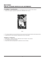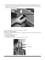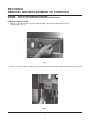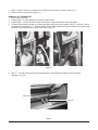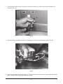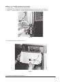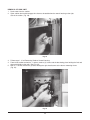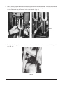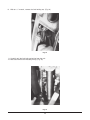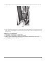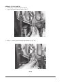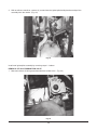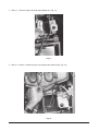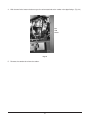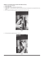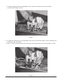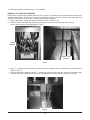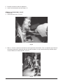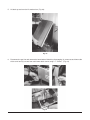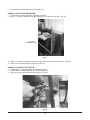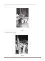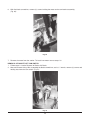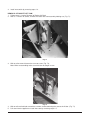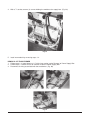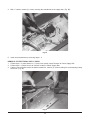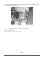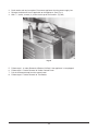
1
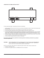
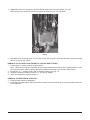
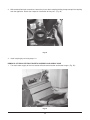
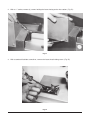
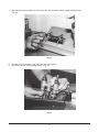
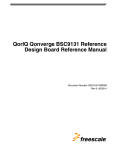
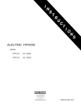
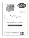
SERVICE MANUAL FOR
GPC12 & GPC12S, GPC16 & GPC16S
GAS PASTA COOKER
ML NOS. 52386, 52423, 52387 AND 52424
MODEL GPC12S
SHOWN
VULCAN-HART COMPANY, P.O. BOX 696, LOUISVILLE, KY 40201- 0696, TIL. (502) 778-2791
FORM 30911 (12-94)
IMPORTANT FOR YOUR SAFETY
THIS MANUAL HAS BEEN PREPARED FOR PERSONNEL QUALIFIED TO SERVICE AND
ADJUST THE EQUIPMENT COVERED BY THIS MANUAL.
POST IN A PROMINENT LOCATION THE INSTRUCTIONS TO BE FOLLOWED IN THE
EVENT THE SMELL OF GAS IS DETECTED. THIS INFORMATION CAN BE OBTAINED
FROM THE LOCAL GAS SUPPLIER.
IMPORTANT
IN THE EVENT A GAS ODOR IS DETECTED, SHUT
DOWN UNITS AT MAIN SHUT OFF VALVE AND
CONTACT THE LOCAL GAS COMPANY OR GAS
SUPPLIER FOR SERVICE.
FOR YOUR SAFETY
DO NOT STORE OR USE GASOLINE OR OTHER
FLAMMABLE VAPORS OR LIQUIDS IN THE
VICINITY OF THIS OR ANY OTHER APPLIANCE.
WARNING
IMPROPER INSTALLATION, ADJUSTMENT,
ALTERATION OR MODIFICATION, SERVICE OR
MAINTENANCE CAN CAUSE PROPERTY
DAMAGE, INJURY OR DEATH. READ THE
INSTALLATION, OPERATING AND MAINTENANCE
INSTRUCTIONS THOROUGHLY BEFORE
INSTALLING OR SERVICING THIS EQUIPMENT.
IN THE EVENT OF A POWER FAILURE, DO NOT ATTEMPT TO OPERATE THIS DEVICE.
2
TABLE OF CONTENTS
Important Safety Information
Codes and Standards Information
Manual Use Information
Data Plate Information
Service Warnings
Tools Required for Servicing
Section l Service Checks
Section ll Service Adjustments
Section lll Removal and Replacement of Controls
Section lV Wiring Information
Page
Page
Page
Page
Page
Page
Pages
Pages
Pages
Page
2
3
3
3
3
3
4-8
9-10
11-57
58
CODES AND STANDARDS
Vulcan-Hart Pasta Cookers are to be installed in accordance with state and local codes, or in the absence of local
codes, the National Fuel Gas Code, ANSI-Z223.1 (latest edition), available from the American Gas Association,
Inc., 1515 Wilson Boulevard, Arlington, VA. 22209 and with ANSI-NFPA Standard #96 (latest edition), Vapor
Removal From Cooking Equipment, available from the National Fire Protection Association, Batterymarch
Park, Quincy, MA 02269.
HOW TO USE THIS MANUAL
This Manual is dedicated to the servicing of the GPC Series Vulcan Gas Pasta Cooker.
The Manual is divided into 4 sections, SERVICE CHECKS, SERVICE ADJUSTMENTS, REMOVAL OF
CONTROL PANEL AND REPLACEMENT OF CONTROLS and WIRING INFORMATION. Refer to the Manual
Table of Contents when looking for specific performance checks or procedures. For additional Technical
assistance contact the Vulcan Hart Service Dept. at the phone number shown on the cover of this manual. Read
the following rating plate information and service warnings before preforming any service work.
RATING PLATE
The rating plate stating model number, serial number, manufacturing date, gas type, voltage and amperage is
located on the inside cooker cabinet door panel.
SERVICE WARNINGS
Hot water and parts can cause burns, use care when servicing this appliance.
If cooker is pulled from the installation area for servicing, reinstall the cooker at least 6" away from any
combustible construction sides and back and 0" away from noncombustible construction.
The high limit is a shut off device which senses the temperature of the appliance to prevent over heating. The
high limit operates independently and will automatically cause equipment shut down should the primary control
fail. If this situation occurs, DO NOT attempt to bypass the high limit. Low water level will cause the high limit
to trip.
TOOLS REQUIRED
The following is a listing of tools required to perform the service checks in this manual
1. Standard set of hand tools.
2. Volt Meter with a sensitivity of at least 20,000 ohms per volts.
3. Temperature tester (thermocouple or digital pyrometer).
4. Gas test kit.
3
SECTION I
SERVICE CHECKS
WARNING:
CERTAIN PROCEDURES IN THIS SECTION REQUIRE ELECTRICAL TEST OR
MEASUREMENTS WHILE POWER IS APPLIED TO THE APPLIANCE. EXERCISE EXTREME
CAUTION AT ALL TIMES. IF TEST POINTS ARE NOT EASILY ACCESSIBLE, DISCONNECT
POWER, ATTACH TEST EQUIPMENT AND REAPPLY POWER TO TEST.
VENTILATION CHECKS
Insure that adequate ventilation has been provided in accordance to all codes as stated on page 3 of this manual.
CAUTION:
The vent of the appliance should be checked every 6 months for restrictions.
GAS SUPPLY CHECKS
NOTE:
If gas supply piping system is going to be tested at a test pressure of in excess of 1⁄2 psig (3.45 Kpa),
the cooker and its individual shut-off valve must be disconnected from the supply line. If the gas
supply pipping system is going to be tested at a test pressure equal to or less than 1⁄2 psig
(3.45Kpa), the individual manual shut-off valve must be closed during testing.
The cooker burners operate in conjunction with a combination gas valve pressure regulator. Verify that the valve
is set for a rating of 4" Water Column for Natural Gas and 10" Water Column for Propane Gas.
If this is proven, verify that the facility pressure is at least 5.5" Water Column for Natural Gas and 12" Water
Column for Propane. Also verify that the gas connection pipe line is at least 1⁄2".
Verify that the cooker is installed in accordance with all local and state authorities having jurisdiction.
GAS CONNECTION CHECK
1. Insure that facility main gas valve is open.
2. Insure that cooker combination gas valve is open.
3. Using a soap solution check for gas leakage at all gas line connection points.
STORE LINE GAS PRESSURE CHECK
1. Connect manometer to the manual gas shut off valve pressure tap.
2. Be sure gas supply line is open and that shut off valve is open
3. Manometer reading should be at least 5.5 in. water column natural and 12 in. water column
for propane gas.
4. If the above is not proven instruct store owner to have pressure problem corrected before
performing any other service work to cooker.
4
COMBINATION VALVE GAS PRESSURE CHECK
1. Check pressure rating of appliance as stated on the cooker door.
2. Turn on all appliance burners.
3. Connect a manometer to the pressure tap of the gas combination valve (gas tap is marked on valve).
4. Open the pressure tap of the manometer.
5. The manometer reading should match the pressure rate inches water column as stated on the appliance
rating plate.
6. If pressure rating is off check the incoming store gas pressure line. If store line pressure is good, continue
with the following steps.
ON-OFF ROCKER SWITCH (D.P.S.T.)
1. Disconnect power.
2. Follow steps under Removal of Cooker Control Panel.
3. Note and disconnect wiring from switch.
4. With an ohm meter and switch in the "off" position measure for continuity across the (2) switch pins that were
connected to power. An ohm reading of infinity should be found.
5. With an ohm meter and switch in the "on" position, measure for continuity across the (2) switch pins that were
connected to power. An ohm reading of 0 should be found.
6. If readings measured in either steps 4 or 5 do not agree with what is stated in these steps replace the switch.
SIGNAL LIGHT
1. With power connected follow steps for Removal of Cooker Control Panel except do not
disconnect the control panel electric supply wire harness.
2. Turn power switch "on".
3. If light fails to illuminate, with a voltage meter measure for voltage of between 110 and 120 volts
across the light connections. If voltage is not found, replace light.
COOKER THERMOSTAT CALIBRATION CHECK
1. Turn cooker on and allow temperature to stabilize by letting the cooker cycle on and off, after reaching the
boil temperature, at least three times.
2. Place a pyrometer sensor in the area of the tank probe tubes.
3. After the stabilizing period the water temperature reading of the pyrometer should be
225 degrees F. plus or minus 10 degrees.
4. If readings are not in tolerance see Section II Services Adjustments in this manual.
HI
1.
2.
3.
4.
LIMIT CHECK
Turn cooker on.
Set temperature at boil setting.
Place pyrometer in tank near the probe tubes.
Observe reading, the hi limit should trip at temperatures of between 235-265 degrees F.
If tripping does not occur replace limit.
BURNER PILOT CHECK
1. Follow steps 1-4 under Removal of Burner.
2. Follow steps 1-3 under Removal of Burner Pilot and Orifice.
3. Examine the pilot body and orifice for clogging.
4. If clogged blow through one end of device. If clogging is still evident soak in warm water or use small probe
device to clear the obstruction. If clogging still persists install new body or orifice as required.
5. Follow steps 1-2 above to install new parts or reinstall repaired parts.
5
TRANSFORMER CHECK
1. Follow steps 1-3 under Accessing of Controls Inside the Control Box.
2. Follow Steps 1-4 under Removal of Transformer.
3. With a volt meter and the appliance "on", check the voltage across the load and line terminals. Voltage
should match that of the transformer markings.
EXAMPLE:
Transformer marked - PRI. 120V
SEC. 24VAC
Means that the load input reading should be 120V and the line output reading should be 24V.
4. If the readings do not match replace the transformer.
5. If readings do match but transformer problem is still suspected, check for resistance across the load terminal
and the line terminal with an ohm meter. If there is no resistance at either end of the lines
replace the transformer.
BASKET LIFT RELAY
1. Follow steps 1-6 under Removal of Basket Lift Back.
2. With power "on" using an ohm meter check for 0 ohms between connections 5 & 3 and also between 6 & 4.
3. With power "off" using an ohm meter check for a coil resistances of above 168 ohms. Also check for
continuity of 0 ohms between connections 1 & 5 and 0 & 6.
4. If any of the above checks do not prove out replace the relay.
BASKET LIFT MICRO SWITCH
1. Follow steps 1-6 under Removal of Basket Lift Back.
2. Remove switch wiring. Engage the switch and with an ohm meter check for continuity across the common
and normally open circuits. If continuity is not shown replace the switch.
BASKET LIFT MOTOR
1. Follow steps 1-6 under Removal of Basket Lift Back.
2. Follow steps 1-7 under Removal of Basket Lift Motor.
3. With volt meter and power on check for voltage to the motor.
4. Verify that the motor voltage agrees with the voltage as stated on the appliance rating plate.
5. Check the motor wire connections.
6. Disconnect power and disconnect the motor wires at the motor terminals.
7. With ohm meter measure the resistance across the terminals. The resistance should be about 28 ohms.
8. If resistance is not correct replace the motor unit.
BASKET LIFT TIMER
1. Follow steps 1-4 under Removal of Cooker Panel.
2. Check for good wire connection at the terminals.
3. Push power switch "on".
4. With a volt meter check for 24Vac across the input terminals of L1 and L2.
5. With a volt meter check for 24Vac across the load terminals after pushing the timer button and
setting the timer. Reading should remain constant at 24vac until the timer runs out.
6. If the above readings are not achieved replace timer.
6
CHECKING THE SPARK IGNITION CIRCUIT
1 2 3 4
MV
BUR
MV PV PV GND
5 6 7
8
9
SEN
SPK
24V 24V W
GNDHOT TH
If erratic ignitor operation is experienced check for the following:
1. If you are experiencing system lock out reset system by turning power switch off, wait several minutes and
turn switch on.
2. Check for good metal to metal contact between the pilot bracket and main burner.
3. Check that all lead connections from the ignition module to the ignitor system are solid.
4. Check that GRD (BUR) lead from the module to the pilot burner is solid and that there is not any damage
to the wiring. If damage is detected either replace the ignitor assembly or the ignitor wire with no.14-18
gauge, moisture-resistant, thermoplastic insulated wire with a min. 105 degrees C (221 degrees F) rating.
5. Check the ceramic flame rod insulator of the ignitor for cracks or evidence of extreme heat. If one or both
of these conditions are found replace the pilot ignitor assembly.
6. Check to insure that ignitor boot is not loose or damaged.
If the above visual checks are positive the following checks should be preformed using a jumper
wire and voltage meter.
WARNING:
WHEN PERFORMING THE FOLLOWING CHECK DO NOT TOUCH THE STRIPPED END
OF THE JUMPER TO THE SPARK TERMINAL. THE IGNITION CIRCUIT GENERATES
OVER 10,000 VOLTS AND ELECTRIC SHOCK CAN RESULT.
NOTE: You will need a short jumper wire made from ignition cable or other heavily insulated wire.
1. Close the manual gas valve
2. Disconnect the ignition cable at the SPARK terminal on the module.
7
3. Push power switch ON and immediately touch one end of the jumper firmly to the GND terminal on the
module. Do not touch the jumper to the SPARK terminal, but, move the free end of the jumper slowly towards
the SPARK terminal until a spark is established.
Pull the jumper slowly away from the SPARK terminal and note the length of the gap when the sparking stops.
See table below for results and action to be taken.
ARC LENGTH
ACTION
1
No arc or arc less than ⁄8".
Verify power at module input terminal.
Replace module power is verified.
Arc 1⁄8" or longer
Voltage output is ok.
If you are getting spark but the spark continues after the pilot is lit check the following.
4.
5.
6.
7.
8.
Check for ground wire and ignition cable continuity.
Check that flame rod is clean.
Check for crack in ceramic insulator.
Check that pilot flame covers rod and is steady and blue. Adjust pilot or pilot flame if necessary.
If the above are all in good condition replace module.
PILOT CHECK (Pilot will not light)
1. Check that all manual gas valves are open, that supply tubing and pressure are good and pilot orifice is not
blocked.
2. Check electrical connections between module and pilot operator on gas combo valve.
3. With volt meter check for 24Vac across PV-MV/PV terminals on module. If voltage is good replace the combo
valve. If voltage is bad replace the module.
BURNER CHECK (Main burner will not light)
1. Check for 24Vac across the MV-MV/PV terminals. If voltage is bad replace the module.
2. Check electric connection between the module and gas combo valve. If good replace the combo valve.
3. Follow steps 1-4 under Removal of Burner and check for clogged burner ports. If clogged use a small probing
device to open the port.
8
SECTION II
PASTA COOKER SERVICE ADJUSTMENTS
ADJUSTMENT OF GAS REGULATOR
1. Follow steps 1-6 under Combination Gas Valve Regulator Check in Section I of this manual.
2. Remove the regulator adjustment cap from the combination valve. (Fig. 1)
Fig. 1
3. Turn the gas adjustment screw clockwise to increase pressure and counterclockwise to decrease pressure.
4. Adjust pressure so that manometer reading agrees with the rating plate.
THERMOSTAT CALIBRATION
1. Follow steps 1-4 under Thermostat Calibration Check in Section I of this manual.
2. Turn temperature dial to boil setting.
3. Allow cooker to boil and temperature to stabilize for several minutes.
9
4. Remove temperature dial knob and insert flat head screw driver into the thermostat shaft rotating the
thermostat adjustment screw to match pyrometer reading to 225 degrees F. at the dial boil setting. Turn
clockwise to increase and counterclockwise to decrease setting. One quarter turn will change the
temperature by 18 degrees. (Fig. 2)
Fig. 2
5. Check the temperature cycling again to insure proper calibration.
BASKET LIFT ARM ADJUSTMENT
This procedure is only required if the basket lift arm is not properly raising or lowering the cooker basket into the
water at the correct level.
1. Turn cooker off and allow it to cool.
2. Remove the cooker baskets.
3. Pull lift arm from the cooker.
4. Turn by hand the adjustment bolt to the required position. (Fig. 3)
LIFT ARM
ADJUSTMENT BOLT
Fig. 3
10
SECTION Ill
REMOVAL AND REPLACEMENT OF CONTROLS
WARNING:
WARNING:
UNPLUG COOKER BEFORE SERVICING.
SHUT OFF GAS AND WATER LINES BEFORE SERVICING.
CONTROL PANEL COOKER
1. With a 1⁄4" socket, remove (2) screws from the upper right and left hand corners of the
control panel. (Fig. 4)
Fig. 4
2. With a 1⁄4" socket, remove (2) #8 hex head screws located on the under flange of the control panel (Fig. 5).
Fig. 5
11
3. Remove the cooker door panel. (Fig. 6)
Fig. 6
4. Fold control panel down. (Fig. 7)
Figs. 7
12
5. Disconnect the main and basket lift (if applicable) wire harness and carefully remove the panel from the fryer.
(Figs. 8)
Fig. 8
REMOVAL OF RINSE STATION CONTROL PANEL
1. With a 1⁄4" socket, remove (2) screws from the upper left and right hand corners of the panel. (Fig. 9)
Fig. 9
13
2. Open the door and with a 1⁄4" socket, remove (2) screws from the right and left corners of the under flange
of the panel. (Fig. 10)
Fig. 10
3. Lift door panel off of the rinse station. (Fig. 11)
Fig. 11
14
4. With a 1⁄8" size allen wrench, loosen the hot and cold water control knob set screws. (Fig. 12)
Fig. 12
5. Pull knobs from the appliance. (Fig 13)
Fig. 13
15
6. Note that this step is only required if the water valves need to be replaced. If fittings
are good go on to step 7.
With a flat blade screwdriver and a 5⁄16" deep socket or wrench, remove (4) screws securing the water fittings
to the control panel. (Fig. 14)
Fig. 14
7. Disconnect the water hoses and remove panel from the rinse station. (Fig. 15)
Fig. 15
16
8. Reinstall rinse station panel by reversing steps 1-7.
REMOVAL OF INDICATOR LIGHT
1. Follow steps 1-5 under Control Panel Removal.
2. From the rear of the control panel unscrew the wire cap of light to be replaced.
3. Squeeze the tabs on both sides of the indicator light being replaced and pull the light out through the
front of the panel. (Fig. 16)
Fig. 16
4. Reinstall new light by reversing steps 1-3.
REMOVAL OF ROCKER SWITCHES
1. Follow steps 1-5 under Cooker Control Panel Removal.
2. From rear of control panel note and remove wire leads from the rocker switch terminals.
3. Press tabs on both sides of the switch and push the switch through the front of the control panel. (Fig. 17)
Retain the switch backup plate for reassembly.
Fig. 17
17
4. Reinstall new switch by reversing steps 1-3.
REMOVAL OF BASKET LIFT TIMER
1. Remove the timer knob using a 1⁄32" allen wrench. (Fig. 18)
Fig.18
2. Remove the timer mounting hardware. (Fig. 19)
Fig. 19
18
3. Follow steps 1- 5 under removal of control panel.
4. Note and remove all wiring associated with the removal of the timer. (Fig. 20)
Fig. 20
5. Install new timer by reversing steps 1-4.
REMOVAL OF RELAY
1. Follow steps 1-5 under Removal of Control Panel.
2. With panel down note and remove all wiring leading to the relay. (Fig. 21)
Fig. 21
19
3. With 1⁄4" socket, remove (2) holding nuts and pull the relay off of the panel. (See Fig. 7)
4. Install new relay by reversing steps 1-3.
REMOVAL OF THERMOSTAT
1. Drain water from tank.
2. Follow steps 1- 5 under Removal of Cooker Control Panel.
3. Follow steps 1-4 under Removal Burner to remove the right hand burner from the cooker.
4. Follow the thermostat wiring to its mounting hardware under the tank assembly. With a 1⁄2" wrench, remove
the packing nut and with an 11⁄16" wrench remove the thermostat bulb mounting nut. Note that the thermostat
hardware is located toward the front of the tank. (Figs. 22)
Figs. 22
5. With a 1⁄4" socket, from inside the tank disengage the thermostat bulb from the tank mounting
brackets. (Fig. 23)
HIGH LIMIT
Thermostat
Fig. 23
20
6. From the control panel using a flat blade screwdriver, remove (2) screws securing the thermostat to
the panel. (Fig. 24)
Fig. 24
7. Note and using a flat blade screwdriver, disengage all wiring form the thermostat body. (Fig. 25)
Fig. 25
8. Install new thermostat by reversing steps 1-7. Be sure that the thermostat wire is not kinked and that the
bulb is not bent while feeding the leads into the tank.
21
REMOVAL OF COOKER CONTROL BOX HOUSING
1. Follow steps 1-5 under Removal of Control Panel.
2. Disconnect limit and basket lift wire harnesses inside the control housing. (See Figs. 8)
3. With a 5⁄16" socket, remove (4) screws holding the housing to the cooker frame. (Fig. 26)
Fig. 26
4. Pull housing from the cooker. (Fig. 27)
Fig. 27
5. Reinstall housing by reversing steps 1-4.
22
REMOVAL OF HIGH LIMIT
1. Drain water from the cooker.
2. Open cooker door and disengage wire harness located below the control housing to the right
side of the cooker. (Fig. 28)
Fig. 28
3. Follow steps 1- 4 for Removal of Cooker Control Housing.
4. From inside cooker tank with a 1⁄4" socket, remove (2) screws and the bracketing piece holding the limit and
thermostat bulbs to the tank. (See Fig. 23)
5. With a 1⁄2" socket, loosen the (2) bolts holding the right hand burner to the burner mounting frame.
(Fig. 29)
Fig. 29
23
6. With (2) hands grasp the burner body and push it upward over the bullet nose pilots. Then tilt the burner head
back and pull the burner away from the cooker. Note that if more room is required to reach the limit hardware
the left side burner may be removed in the same manner. (Fig. 30)
BULLET
NOSE PILOT
Fig. 30
7. The high limit fitting is the one toward the rear of the tank. With 1⁄2" wrench, remove the high limit packing
nut. (Fig. 31)
Fig. 31
24
8. With an 11⁄16" wrench, remove the limit holding nut. (Fig. 32)
Fig. 32
9. Carefully pull the limit bulb and wiring from the unit.
10. Note and remove the limit body wiring. (Fig. 33)
Fig. 33
25
11. With a 1⁄4" socket, remove (2) holding screws securing the limit body to the mounting bracket. (Fig. 34)
Fig. 34
12. Install new limit by reversing steps 1-9. When installing new limit do not kink the limit wire or bend the limit
probe. Make sure that the probe is mounted intimately against the burner tube. Wrap limit holding nuts with
new teflon tape.
REMOVAL OF COOKER BURNERS
1. Follow steps 1-5 under Removal of Control Panel.
2. Follow steps 1-4 under Removal of Control Panel Housing.
3. With a 1⁄2" socket, loosen (2) bolts holding the burner to the burner mounting frame. (See Fig. 29)
4. With (2) hands grasp the burner body and push it upward over the bullet head burner pilot. Tilt the burner
head back and lift it from the cooker. (See Fig 30)
5. Reinstall burner by reversing steps 1-4.
26
REMOVAL OF BULLET NOSE BURNER PILOT AND ORIFICE
1. Follow steps 1-4 under Removal of Cooker Burners.
2. With a 5⁄16" wrench, remove the pilot orifice. (Fig. 35)
Fig. 35
3. With channel locks remove the pilot body. (Fig. 36)
Fig. 36
4. Install new orifice or pilot body by reversing steps 1-3. Use pipe dope when installing pilot body.
27
REMOVAL OF PILOT IGNITOR
1. Follow steps 1-4 under Removal of Burners.
2. Pull the igniter boot from the ignitor. (Fig. 37)
Fig. 37
3. With a 7⁄16" wrench, loosen the pilot tube holding nut. (Fig. 38)
Fig. 38
28
4. With an offset screwdriver, remove (2) screws from the ignitor/pilot holding bracket and pull the
assembly from the cooker. (Fig. 39)
Fig. 39
Install new ignitor/pilot assembly by reversing steps 1-4 above.
REMOVAL OF GAS COMBINATION VALVE
1. Note and remove all wiring associated with the combo valve. (Fig. 40)
Fig. 40
29
2. With a 7⁄16" wrench, loosen the pilot tube holding nut. (Fig. 41)
Fig. 41
3. With a 3⁄4" wrench, remove the gas line compression elbow fitting. (Fig. 42)
Fig. 42
30
4. With channel locks loosen the burner gas line union attached to the combo valve pipe fittings. (Fig. 43)
GAS
LINE
UNION
Fig. 43
5. Remove the combo valve from the cooker.
31
REMOVAL OF DISCARD HOSE (COOKER AND DRAIN STATION)
1. Drain station to be worked on.
2. Open cabinet door.
3. Follow steps 1-5 for the Removal of Control Panel.
4. Follow steps 1-4 under Removal of Cooker Control Box Housing ( this procedure is not required for the rinse
station).
5. With a standard flat blade screwdriver, loosen the hose clamp. (Fig. 44)
Fig. 44
6. Pull hose from the station drain tube. (Fig. 45)
Fig. 45
32
7. Pull hose from scrap box. (Fig. 46)
Fig. 46
8. Install discard hose by reversing steps 1-7.
REMOVAL OF SCRAP BOX (COOKER AND DRAIN STATION)
1. Open cooker door.
2. Pull scrap box handle away from cooker. (Fig. 47)
Fig. 47
33
3. Support box with one hand on the under side and remove box from the cooker. (Fig. 48)
Note that you may need to lift the box up slightly to remove it from the slide track.
Fig. 48
4. Reinstall box by reversing steps 1-3. Be sure to align the scrap box drain tube into the scrap box housing
tube in the rear of the cooker.
REMOVAL OF HOT AND COLD WATER FILL VALVES AND FITTINGS
1. Follow steps 1-5 under removal of control panel.
Note: When hose fittings are removed check to insure that the hose washers are in good condition. If they
are cracked or worn looking, replace the washer before reinstalling hose. Remove hose fittings.
2. Disconnect (4) 5⁄16 holding screws and (2) holding bracket. (See Fig. 14)
3. Remove the fitting assembly made by a 1⁄2" tee and (2) elbows
4. Install new fittings by reversing steps 1-3 .
REMOVAL OF REAR DRAIN COUPLING
1. Empty discard container completely.
2. Disconnect the cooker/drain station and move it away from the floor drain in an area assessable to the rear
of the appliance.
34
3. With standard flat blade screwdriver, loosen the (2) rear drain coupling holding clamps and pull the coupling
from the appliance. Retain the clamps for installation of new part. (Fig. 49)
Fig. 49
4. Install coupling by reversing steps 1-3.
REMOVAL OF DRAIN STATION FAUCETS ASSEMBLY AND SPRAY HOSE
1. Turn main water supply of the rinse station off and remove basket and basket hanger. (Fig. 50)
Fig. 50
35
2. With a 5⁄16" socket, remove (4) screws holding the faucet hosing to the rinse station. (Fig. 51)
Fig. 51
3. With a standard flat blade screwdriver, remove the faucet head holding screw. (Fig. 52)
Fig. 52
36
4. With a philips head screwdriver, remove the hot and cold water faucet handle holding screws.
(Fig. 53)
Fig. 53
5. Remove the faucet handles and head from the rinse station.
6. Disconnect the hot and cold water hoses. (Fig. 54)
Fig. 54
37
7. To change fitting washer with an adjustable wrench remove the faucet stem and nut assembly
from the cast iron body. (Fig. 55)
Fig. 55
8. To tighten the handle stem use an adjustable wrench. Be sure not to over tighten. If stem is too tight it will
wear quicker and cause leaks .
9. With a 3⁄4" wrench, disconnect the spray hose water line attached to the cast iron faucet body. (Fig. 56)
Fig. 56
38
10. Reinstall faucet by reversing steps 1-10 as needed.
REMOVAL OF SCRAP BOX HOUSING
Note that the scrap box has formed flanges on all 4 corners. These flanges are used to attach the box to the
appliance base frame. There are (3) screws in each flange. Removal of these screws in the front and back
sections of the cooker will allow the scrap box housing to be removed.
1. Open cabinet door, empty and remove scrap box drawer. (See Fig. 48)
2. From the front of unit with your hand reach around the front frame channel and feel for the (3)
screws and scrap box mounting bracket. (Fig 57)
FRONT
CHANNEL
BEHIND FRONT
CHANNEL
Fig. 57
3. With a 5⁄16" socket remove (3) holding screws from each flange on either side of the front frame channels.
(Refer to Fig. 57)
4. From the front of the appliance with a 5⁄16" socket and a long socket extension, remove (3) holding screws
located in the back section of the cabinet on the body frame rear left and right channels. (Fig. 58)
REAR CHANNELS
Fig. 58
39
5. Remove the housing from the appliance.
6. Install new housing by reversing steps 1-5.
REMOVAL OF DRAIN BALL VALVE
1. Drain tank.
2. Close drain ball valve. (Fig. 59)
Fig. 59
3. With a 1⁄2" wrench, remove nut and washer securing the ball valve handle. (This is an optional step if the ball
valve being removed is located on the sink side of the cooker.) It may also be necessary to follow steps 14 under Removal of Cooker Burners. (Fig. 60)
Fig. 60
40
4. With a pipe wrench remove nipple. (Fig. 61)
BALL
VALVE
NIPPLE
Fig. 61
5. With pipe wrench remove the ball valve. (Fig 61)
6. Install new valve by reversing steps 1-5.
REMOVAL OF BASKET LIFT BACK (OPTIONAL FEATURE)
1. Remove all baskets and basket support racks from tank.
2. Drain appliance tank, disconnect unit power and tipping restraint. Move appliance to an area where the
back is completely accessible.
3. Remove the basket lift arm. ( See Fig. 3)
4. Remove (14) screws from the upper back of the basket assembly using a 1⁄4" socket. (Fig. 62)
Fig. 62
41
5. Lift back up and over the lift mechanism. (Fig. 63)
Fig. 63
6. Disconnect the gas line and remove the lower basket lift back by disengaging (2) screws at each lower side
of the cover and (2) screws from each lower back corner using a 1⁄4" socket . (Fig. 64)
Fig. 64
42
7. To reinstall basket back panels reverse steps 1-6.
REMOVAL OF LIFT ROD MECHANISM
1. Follow steps 1-6 under Removal of Basket Lift Backs
2. With a 1⁄2" wrench, remove the nut that attaches the lift rod to the lift bar. (Fig. 65)
LIFT ROD
ATTACHMENT NUT
Fig. 65
3. With a 5⁄16" socket, remove (6) screws from the rod mechanism holding bracket. (Fig. 65)
4. Install new lift rod assembly by reversing steps 1-3.
REMOVAL OF BASKET LIFT MOTOR
1. Follow steps 1-6 under Removal of Basket Lift Backs.
2. Follow steps 1-2 under Removal of Lift Rod Mechanism.
3. Note and remove wiring from the cam switch. (Fig. 66)
Fig. 66
43
4. With 5⁄16" socket, remove (2) nuts holding the cam lift bracket to the cooker back. (Fig. 67)
Fig. 67
5. Remove motor wiring. (Fig. 68)
Fig. 68
44
6. With flat blade screwdriver, remove (2) screws holding the motor to the cam bracket assembly.
(Fig. 69)
Fig. 69
7. Remove the motor from the cooker. To install new motor reverse steps 1-6.
REMOVAL OF BASKET LIFT CAM SWITCH
1. Follow steps 1-6 under Removal of Basket Lift Backs
2. Note and remove wiring. With a standard flat blade screwdriver, and a 5⁄16" wrench, remove (2) screws and
holding nuts from the cam switch. (Fig.70)
Fig. 70
45
3. Install new switch by reversing steps 1-3.
REMOVAL OF BASKET LIFT CAM
1. Follow steps 1-6 under Removal of Basket Lift Back.
2. With a 1⁄2" wrench or socket, remove the lift bar and cam assembly holding nut. (Fig. 71)
Fig. 71
3. With an allen wrench loosen the cam set screw. (Fig. 72)
Note: When reassembling make sure wires do not tangle in cam.
Fig. 72
4. With an off set flat blade screwdriver, remove screws mounting the cam to the lift bar. (Fig. 71)
5. Pull cam from the appliance. Install new cam by reversing steps 1-5.
46
REMOVAL OF PASTA COOKER POWER SUPPLY BOX (STAND ALONE)
1. Follow steps 1-6 under Removal of Basket Lift Back if appliance is equipped with this option.
2. Note and disconnect all wiring and wire harnesses. (Fig. 73)
REAR BODY SUPPORT
SCREWS (2) EACH SIDE
Fig. 73
3.
4.
5.
6.
Follow steps 1-2 under Removal of Lift Rod Mechanism if basket lift option is included on the appliance.
With a 5⁄16" socket, remove (2) screws holding the motor mount support plate to the cooker. (See Fig. 67)
With a 5⁄16" socket, remove (4) screws securing the rear body support bracket to the cooker. (See Fig. 73)
With a 7⁄16" socket, and/or open end wrench remove (2) bolts and hardware securing the power supply box
to cooker. (Fig. 74)
Fig. 74
47
7. With a 5⁄16" socket and a wrench, disconnect the electric supply cord holding strap(s). (Fig. 75)
INLET GAS TUBE UNION
(2) EACH
SIDE OF COOKER
Fig. 75
8. If necessary with a 5⁄16" socket, remove (4) screws securing the basket lift bottom plate to the appliance
frame. (Fig. 76)
Fig. 76
9. Pull the power supply box out through the back of the unit. To reinstall box reverse steps 1-8.
48
REMOVAL OF PASTA COOKER POWER SUPPLY BOX ( WITH RINSE STATION)
1. Follow steps 1-8 under Removal of Pasta Cooker Supply Box ( stand alone)
2. From the rinse station with a 7⁄16" wrench, disconnect the "U" bolt bracket from the hot and cold water fitting
assemblies. (Fig. 77)
Fig. 77
3. Disconnect the rinse station hot and cold water hoses. (Fig. 78)
Fig. 78
49
4. With a 5⁄16" socket, remove (4) screws holding the rinse station support back bracket. (Fig. 79)
Fig. 79
5. Pull the cooker power supply box through the rinse station back and out of the appliance. (Fig. 80)
Fig. 80
50
6. Reinstall box by reversing steps 1-5.
ACCESS OF CONTROLS INSIDE THE POWER SUPPLY BOX
1. Follow steps 1-8 (stand alone) or 1-5 (with rinse station) under Removal of Power Supply Box.
2. With a 5⁄16" socket, remove (2) screws securing the supply box cover. (Fig. 81)
Fig. 81
3. Controls are now exposed and can be serviced. To reinstall box reverse steps 1-2.
REMOVAL OR ACCESSING THE SPARK IGNITOR MODULE
1. Follow steps 1-8 (stand alone) or 1-5 (with rinse station) under Removal of Power Supply Box.
2. Follow steps 1-2 under Access of Controls Inside the Power Supply Box.
3. Disconnect all wiring associated with the module. (Fig. 82)
Fig. 82
51
4. With a 1⁄4" socket, remove (4) screws holding the module to the supply box. (Fig. 83)
Fig. 83
5. Install new module by reversing steps 1-4.
REMOVAL OF TRANSFORMER
1. Follow steps 1-9 (stand alone) or 1-5 (with rinse station) under Removal of Power Supply Box.
2. Follow steps 1-2 under Access of Controls Inside the Power Supply Box.
3. Disconnect all wiring associated with the transformer. (Fig. 84)
Fig. 84
52
4. With 1⁄4" socket, remove (2) screws securing the transformer to the supply box. (Fig. 85)
Fig. 85
5. Install new transformer by reversing steps 1-4.
REMOVAL OF ELECTRICAL SUPPLY CORD
1. Follow steps 1-9 (stand alone) or 1-5 (with rinse station) under Removal of Power Supply Box.
2. Follow steps 1-2 under Access of Controls Inside the Power Supply Box.
3. From the rear of the box with a flat blade screwdriver, remove (2) screws holding the cord mounting clamp
to the box. (Fig. 86)
Fig. 86
53
4. With small flat blade screwdriver, remove all wiring with in the box that attaches the supply cord to the
terminal block and the ground lug. (Fig. 87)
Fig. 87
5. Pull the cord from the appliance. Install the cord by reversing steps 1-4.
REMOVAL OF COOKER TANK
1. Remove basket(s) and basket hanger. (Fig. 88)
Fig. 88
54
2. Drain cooker tank and scrap box. Disconnect appliance from the power supply line.
3. Remove the basket lift arm if applicable to the appliance. (See Fig. 3)
4. With 5⁄16" socket, remove (2) screws at the top of the flue box. (Fig. 89)
Fig. 89
5.
6.
7.
8.
Follow steps 1- 6 under Removal of Basket Lift Back if the appliance is so equipped.
Follow steps 1-5 under Removal of Cooker Control Panel.
Pull the thermostat knob from the control panel.
Follow steps 6-7 under Removal of Thermostat.
55
9. Carefully fold the thermostat wiring and body so that it will set between the burners. Wedge it securely
so that it will not fall out when the tank assembly is lifted from the appliance.
10. Follow steps 1-5 under Removal of Cooker Power Supply Housing.
11. Remove the ignitor boot. (Fig. 90)
Fig. 90
12. With a 7⁄16" socket, remove (2) 1/4-20 nuts (from under the front of the base frame) that secure the tank
support bracket to the frame assembly.
13. From rear of appliance disconnect the inlet gas tube union. (See Fig. 76)
14. Disconnect drain hose and water fill hoses.
15. With the assistance of another person, stand in front of the cooker, grasp the back and the front of tank then
carefully tilt the tank back forward and lift tank out of the cooker body. (Fig. 91)
TANK BACK
Fig. 91
56
16. Note wiring and remove all controls from the old tank. Retain the controls and hardware for
reassembly to the new tank. (Review section lll, Removal of Thermostat, High Limit, Combo Valve Burners,
Burner Pilot and Orifice and Ignitor and Pilot Assembly). If you are in doubt of control removal procedures.
17. Install all the old controls onto the new tank.
18. Check that controls are wired properly.
19. Install new tank assembly by reversing steps 1-15.
REMOVAL OF RINSE STATION TANK ASSEMBLY
1. Remove the basket hanger, basket support rack and basket(s) (Fig 92).
Fig. 92
2.
3.
4.
5.
Drain the tank and scrap box.
From rear of the unit disconnect the main water line and fill hoses.
Follow steps 1-7 under Removal of Rinse Station Control Panel.
From the front of the appliance with a flat blade screwdriver, loosen the discard hose clamp and disconnect
the discard hose from the tank.
57
6. Follow steps 1-6 and step 10 under Removal of Drain Station Faucet and Spray Hose.
7. Remove the scrap box from the appliance. (See Fig. 48)
8. With a 7⁄16" socket, remove (2) 1⁄4-20 nuts from under the front base frame that secures the tank support
bracket to the frame. (Fig. 93)
9. Follow step 16 under Removal of Cooker Tank. (See Fig. 91)
10. Install new tank by reversing steps 1-10.
WATER
FILL
HOSES
REMOVE (2) NUTS
ATTACHED TO
THESE BOLTS
Fig. 93
58
BASKETLIFT CONTROL ASSEMBLY
REFER TO D-418519 FOR
WIRING INFORMATION
DRAWING NO. REV
420843-1
B
SECTION IV
WIRING INFORMATION
59
60
FORM 30911 (12-94)