1
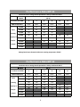
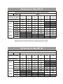
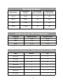
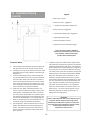
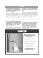
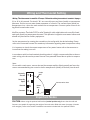
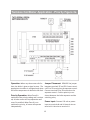
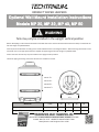
INDIRECT INDIRECT INDIRECT WATER WATER WATER HEATERS HEATERS HEATERS Installation Installation Installation & Operating &&Operating Operating Instructions Instructions Instructions Models Models Models MPMP 20, MP20, MP 20,MP 32, MP32, MP 32,MP 40 MP40 &40 MP &&MP 50 MP50 50 TO THE INSTALLER: This manual is TO THE INSTALLER: This manual is TO THE INSTALLER: This manual is the property of the owner and the property of the owner and the property of the owner and must be affixed near the water must be affixed near the water must be affixed near the water heater for future reference. heater for future reference. heater for future reference. TO THE OWNER: This water heater TO THE OWNER: This water heater TO THE OWNER: This water heater should be inspected annually by a should be inspected annually by a should be inspected annually by a qualied Service Agency. qualied Service Agency. qualied Service Agency. WARNING WARNING WARNING Improper Improper Improper installa�on, installa�on, installa�on, adjustment, adjustment, adjustment, altera�on, altera�on, altera�on, serviceservice orservice maintenance or maintenance or maintenance can cause cancan cause injury cause injury or injury or or property property property damage. damage. damage. Refer to Refer this Refer tomanual. this to this manual. For manual. ForFor assistance assistance assistance or addi�onal or addi�onal or addi�onal informa�on, informa�on, informa�on, consultconsult consult a qualied a qualied a qualied Installer Installer or Installer Service or Service orAgency. Service Agency. Agency. FORFOR YOUR FOR YOUR YOUR SAFETY SAFETY SAFETY Do notDo store Do notnot or store use store or gasoline use or use gasoline or gasoline other or other amma‐ or other amma‐ amma‐ ble vapors bleble vapors and vapors liquids andand liquids in liquids the in vicinity the in the vicinity ofvicinity thisof orthis of this or or any other anyany appliance. other other appliance. appliance. Installa�on Installa�on Installa�on and service andand service service must be must performed must be performed be performed by a qualied by abyqualied a qualied Installer Installer or Installer or or ServiceService Agency. Service Agency. Agency. NEW JERSEY HEADQUARTERS • 439 MAIN ROAD, TOWACO, NJ 07082 PHONE: 800-221-1522 • WEBSITE: WWW.DHTNET. COM Manufacturers and Designers Since 1938 CONTENTS Contents finished flooring or carpeted surfaces. DHT CANNOT BE HELD LIABLE for damage caused by water from the water heater, pressure relief valve, or related fittings. Closets without drains and carpeted areas are examples of unsuitable locations for any water heater. Select a location as centralized within the piping system as possible. The heater should be located in an area not subject to freezing temperatures in any location selected. It is recommended that a suitable drain pan be installed under the water heater. This pan shall be a minimum of 50mm (2 in.) deep and have a diameter that is a minimum of 50mm (2 in.) greater than the diameter of the water heater. Suitable piping shall connect the drain pan to a properly operating floor drain. I II III SAFETY PRODUCT SELECTION PERFORMANCE RATINGS/SPECS IV INSTALLATION/PIPING V WIRING VI MAINTENANCE VII WARRANTY Relief Valve Requirements Caution: To reduce the risk of excessive pressures and I Safety I SAFETY The warranty on this water heater is in effect only when the water heater is installed and operated in accordance with these instructions. The manufacturer of this water heater will not be liable for any injury or property damage resulting from failure to comply with these instructions. WARNING! This water heater must be installed strictly in accordance with the instructions enclosed, and local electrical, fuel and building codes. It is possible that connections to the water heater or the water heater itself may develop leaks. IT IS THEREFORE IMPERATIVE that the water heater be installed so that any leakage of the tank or related water piping is directed to an adequate drain in such a way that it cannot damage the building, furniture, carpeting, adjacent areas, lower floors of the structure or other property subject to water damage. This is particularly important if the temperatures in this water heater, install temperature and pressure protective equipment required by local codes. It should be no less than a combination temperature and pressure relief valve certified by a nationally recognized testing laboratory that maintains periodic inspection of production of listed equipment or materialals, as meeting the latest edition of ANSI Z21.22: Requirements for Relief Valves and Automatic Gas Shut-off Devices for Hot Water Supply Systems. This valve must be marked with a maximum set pressure not to exceed the marked MAXIMUM working pressure of the water heater (150 PSI). Install the valve into an opening provided and marked for this purpose in the water heater, and orient it or provide tubing so that any discharge from the valve will exit only within 6 inches above, or any distance below the structural floor and cannot contact any live electrical part. The discharge opening must not be blocked or reduced in size under any circumstances. The end of the relief pipe opening should terminate near a floor drain or other suitable location not subject to blocking or freezing. DO NOT thread, plug or cap the relief pipe opening. DANGER HOT BURN • Water temperatures over 125ºF can cause severe burns instantly or death from scalds. • Children, disabled, and elderly are at the highest risk of being scalded. • See instruction manual before setting temperature at water heater. • Feel water before bathing or showering. • Temperature limiting valves are available, see manual. NOTICE The Techtanium Indirect-fired water heater is deemed to be used in a "commercial setting" if at any time the unit is operated at a temperature over 150ºF. Refer to warranty for additional information. 2 II PRODUCT SELECTION/ II Product Selection PERFORMANCE 1. The following g u ide line s apply to residential systems only. For commercial or institutional installations contact the factory directly for assistance. 2. Determine the quantity of domestic hot water required. Factors to consider: a. Estimate typical peak hour demand. Determine the general time of day (morning, noon, evening) when the most hot water is used. Use chart below to determine potential maximum usage. Estimate of Peak Domestic Hot Water Usage Average Gallons of Hot Water per Usage Use Shower Bath Shaving Hands and Face Washing Hair Shampoo Hand Dish Washing Automatic Dish Washing Food Preparation Wringer Clothes Washer Automatic Clothes Washer Times Used During One Hour Times Used During One Hour 20 20 2 4 4 4 14 5 26 32 = = = = = = = = = = x x x x x x x x x x x x x x x x x x x x Total Peak Hour Demand = b. Estimate unusual peak draw demand. Whirlpool baths, hot tubs, and multiple head showers require large quantities of hot water in a short period of time. Contact fixture manufacturer for quantity of water required. Generally speaking, these circumstances can only be met with larger storage volumes. c. Domestic Water Temperature. Most residential usage will be satisfied with 119ºF water, the temperature setting recommended by the Consumer Product Safety Commission. Some applications s u c h as laundry and dishwashers may require a higher temperature. Ratings can be improved by increasing Techtanium thermostat setting and using a mixing valve to temper the hot water to the proper temperature. When temperatures greater than 119ºF are required, use a mixing valve at the outlet of the water heater or anti-scald fittings at point of use. III Specifications and Performance Units MP Model 20 32 40 50 42.3 52.9 Tank Capacity Gallons 21.2 31.7 Minimum Recommend Power Btu/Hr. 75,000 95,000 Maximum Working Pressure P.S.I. 150 150 150 150 Maximum Temperature Degrees F 194 194 194 194 Weight (empty) Pounds 74.8 99 112.2 136.4 Weight (full) Pounds 251.4 363.1 464.6 577 3 115,000 140,000 Connection Diagram Thermometer Boiler Supply Boiler Return T&P Relief Valve Hot Water Outlet Cold Water Inlet Boiler Return Boiler Supply Tank Thermostat (located under cover) Drain Drain Valve Front of Tank Dimensions A B MP 20 MP 32 MP 40 MP 50 A 22.4" 22.4" 22.4" 22.4” B 31.1" 39½" 47.9" 56¾" C 27.6" 36" 44.4" 53.2" C 4 Pressure Drop Table Primary Flow Rate Model Number 5 GPM 8 GPM 12 GPM Unit MP 20 1.2 2.9 6.2 / hd MP 32 1.6 3.8 8.0 / hd MP 40 1.6 3.6 7.6 / hd MP 50 1.8 4.2 8.8 / hd Pressure Drop Graph Pressure Drop Graph Head Loss FT/HD 10.0 8.0 50 32 40 6.0 20 MP 20 4.0 MP 32 2.0 MP 40 - MP 50 5 GPM 8 GPM 12 GPM Primary Flow Rate 5 Performance Data MP 20 Con nuous Draw Ra ngs Based Upon Boiler’s Ability to Maintain 180º F Model MP 20 Circulator Flow GPM 5 5 8 8 12 12 DHW Temperature 120ºF 140ºF 120ºF 140ºF 120ºF 140ºF 45,000 76 56 76 56 Boiler 60,000 95 69 95 69 Hea ng 75,000 116 83 116 83 95,000 120 86 134 95 142 101 115,000 120 86 134 95 156 111 Btu/Hr. 140,000 134 95 156 111 Output 165,000 168 119 195,000 Capacity in Ra ngs based upon domes c cold water entering temperature of 58ºF Performance Data MP 32 Con nuous Draw Ra ngs Based Upon Boiler’s Ability to Maintain 180º F Model MP 32 Circulator Flow GPM 5 5 8 8 12 12 DHW Temperature 120ºF 140ºF 120ºF 140ºF 120ºF 140ºF 45,000 106 78 106 78 60,000 134 97 134 97 75,000 162 116 162 116 95,000 168 120 188 134 198 141 115,000 168 120 188 134 219 155 140,000 188 134 219 155 165,000 236 167 Boiler Hea ng Capacity in Btu/Hr. Output 195,000 6 Performance Data MP 40 Con nuous Draw Ra ngs Based Upon Boiler’s Ability to Maintain 180º F Model MP 40 Circulator Flow GPM 5 5 8 8 12 12 DHW Temperature 120ºF 140ºF 120ºF 140ºF 120ºF 140ºF 45,000 110 82 110 82 Boiler 60,000 138 101 138 101 Hea ng 75,000 166 120 166 120 95,000 172 124 192 138 202 145 115,000 172 124 192 138 223 159 Btu/Hr. 140,000 192 138 223 159 Output 165,000 240 171 Capacity in 195,000 Ra ngs based upon domes c cold water entering temperature of 58ºF Performance Data MP 50 Con nuous Draw Ra ngs Based Upon Boiler’s Ability to Maintain 180º F Model MP 50 Circulator Flow GPM 5 5 8 8 12 12 DHW Temperature 120ºF 140ºF 120ºF 140ºF 120ºF 140ºF 45,000 117 91 117 91 60,000 142 108 142 108 75,000 167 125 167 125 95,000 201 148 201 148 201 161 115,000 201 148 231 169 236 186 140,000 231 169 252 198 165,000 252 198 Boiler Hea ng Capacity in Btu/Hr. Output 195,000 7 IV Installation & Piping The Loca on of the Techtanium heater: Locate the heater so that there is easy access to the control, piping, valves, drain and heater for future servicing and maintenance. The heater is to be kept in an area where it is not exposed to freezing tem‐ peratures. Also, the heater must be located in an area where a leak (eg. from the piping or fi ngs, from any tem‐ perature and relief valve discharge, or from the tank itself), will not cause personal harm or dam‐ age the surrounding area. The tank should be installed in an area with a floor drain or in a pan suitable for water heaters. Read the Installa on and Opera ng Instruc ons manual thoroughly. Follow recommended piping and wiring diagrams. Upon comple ng installa on, fill the tank with water. While filling it leave a hot water faucet open un l a steady stream of water is flowing. Then, shut the faucet and check for any leaks throughout the en re system. The Tank should be installed in an area with a floor drain or in a pan suitable for water heaters. DHT will not be held liable for any damages caused by water leakage. The floor or area where the tank is installed must be capable of suppor ng the tank when filled with water. (Refer to the Specifica ons Table on the page 3) FOR YOUR SAFETY: Do not store or use gasoline or other flammable vapors or liquids in the vicinity of this or any other appliance. Controls on this appliance could ignite vapors causing an explosion. General: a. All plumbing must be in accordance with the requirements of the authority having jurisdic on. b. Use both thread tape and pipe dope on all mechanical connec ons. c. Zone valve (if used) and circulator must be sized to provide minimum flow rate specified in the table to the right, Flow Specifica ons. Use 1 inch nominal copper tubing for flows greater than 7 GPM be‐ tween the boiler and heat exchanger. See the tables on Fric on Loss. Point of emphasis: using a zone valve without a full bore may cause high pressure drop which will adversely affect performance. Use extreme care when selec ng zone valve. d. All piping must be adequately supported. e. Allow for thermal expansion. f. Dielectric Unions (recommended) ‐used to electrically isolate the Techtanium tank from the connect‐ ed domes c water piping. This helps to minimize the possibility of corrosion damage. 8 Flow Specifications Flow Specifications Model Number Recommended Flow Rate Heat Exchanger Pressure Drop ( . hd.) Domes c Water Connec on Sizes MP‐20 5 GPM 1.2 3/4” MP‐32 8 GPM 3.8 3/4” MP‐40 12 GPM 7.6 3/4” MP‐50 12 GPM 8.8 3/4” Friction Loss per 100’ of Tubing (psi) Tubing Type Flow Rate 10 GPM Flow Rate 15 GPM Type K 3.1 psi 6.5 PSI Type L 2.7 psi 5.7 psi Type M 2.3 psi 4.7 psi Friction Loss Allowance for Copper Fittings (ft. of tubing) Fi ng Wrought Cast 90º Elbow 1 4 45º Elbow 1 2 Tee—Run 1/2 1/2 Tee‐Branch 3 5 Long radius 90º Elbow 2 ‐ 180º Bend 2 ‐ Gate Valve ‐ 1 9 IV Installation/Piping (cont’d) Legend E G H F A B C D Domes�c Water: A Ball Valve—Typical B Dielectric Union—Suggested C Temperature & Pressure Relief Valve D Heat Trap Loop—Suggested E Thermosta�c Mixing Valve –Suggested F High Temperature Outlet G Mixed Temperature Outlet H Expansion Tank in Cold Water Supply Note: For drawing clarity, addiƟonal isolaƟon valves and other accessories have been omiƩed. Follow normal piping pracƟces when installing tank. F. Temperature & Pressure Relief Valve: (T&P) Install a T&P relief valve (long element type) into the separate tapping designated for the T&P valve. Install temper‐ A. Install isola�on valve between the water supply and ature and pressure protec�ve equipment required by the cold water inlet of the tank for ease of service. local codes, but no less than a combina�on tempera‐ B. Installing a heat trap in the domes�c hot water outlet ture and pressure relief valve cer�ed as mee�ng the piping will improve energy efficiency and reduce pip‐ requirements for relief Valve and Automa�c Shutoff ing heat loss. Devices for Hot Water systems, ANSI Z21.22, by a C. A Thermosta�c Mixing Valve is recommended and na�onally recognized tes�ng laboratory that main‐ may be required by local codes. The valve will blend tains periodic inspec�on of listed equipment or mate‐ the tank output water with cold water to achieve a rials. The valve must be oriented, provided with tub‐ more constant mixed temperature. The risk of scald‐ ing or otherwise installed so that discharge can exit ing is not eliminated by use of a mixing valve. Refer only within six (6) inches above, or at any distance to the installa�on instruc�ons provide by the mixing below, the structural oor, and cannot contact any valve manufacturer for proper installa�on. electrical part. The valve must be piped to an area D. Expansion Tank: When a back‐ow device or “no‐ where discharge will not cause personal injury or return” valve is installed in the piping system a Ther‐ damage the surrounding area. mal Expansion Tank designed for use in a domes�c hot water system will be required. Install the tank in the cold water piping close to the tank between the WARNING tank and the back‐ow device. (see piping diagram) Install a T&P relief valve with a rated capacity equal Refer to Thermal Expansion Tank manufacturer’s lit‐ or greater that the output of the energy source. erature for sizing and installa�on informa�on. Removal of the T&P Valve or failure to replace the E. Vacuum Breaker: DHT recommends that a vacuum valve will release the manufacturer from any claim breaker be installed on the domes�c piping to the which might result from excessive heater. The vacuum breaker protects the heater in temperatures and pressures the event that the tank pressure falls below atmos‐ pheric pressure. 10 V Wiring All wiring must be done in accordance with Na‐ �onal, State and local codes. Adhere to the Na‐ �onal Electric Code ‐ ANSI/NFPA 70‐1990 in the absence of any other codes. Power must be shut off before installing or servic‐ ing the heater. A separate shut off switch should be installed to support future servicing or an emergency shutdown. The en�re hea�ng system should have its own designated electrical circuit. The Techtanium heater operates in much the same way as an addi�onal hea�ng zone, either u�lizing the same circulator as household hea�ng or its own circulator. The heater temperature is maintained by the use of an immersion type aq‐ uastat. The aquastat is installed into the im‐ mersion well on the heater. The aquastat operates in much the same way as a thermostat. When the temperature falls inside the tank the set of contacts make (close) and when the temperature rises the contacts break (open). The aquastat should be �ed into the boiler sys‐ tem and controls. When the tank calls for heat the aquastat contacts close and signal the boiler con‐ trols, allowing the boiler to maintain temperature and proper opera�on of the tank circulator. DHT recommends the use of a priority control to help the boiler maintain desired temperature and sa�sfy the tank's BTU requirements. The Techtanium heater recovery ra�ngs are based on the boiler's ability to maintain 180 degrees Fahrenheit. It is important that the installer, plumber or hea�ng technician responsible for installing the heater, make certain that the boiler capacity (BTU) is adequate to sa�sfy the heater's BTU requirements. Water temperature over 125ºF can cause severe burns instantly or death from scalds. Children, disabled and elderly are at highest risk of being scalded. See instruc�on manual before se�ng temperature at water heater. Feel water before bathing or showering. Temperature limi�ng valves are available, see manual. 11 Wiring andThermostat Thermostat Setting Wiring and Setting Wiring: Wiring: The thermostat is rated for 15 amps. Follow the wiring instruc�ons in sec�on V pages pages The thermostat thermostatisis israted ratedfor for15 15amps. amps.Follow Followthe thewiring wiringinstruc�ons instructions section pages rated for 15 amps. Follow the wiring instruc Wiring: The ons in ininsec�on sec on VV V pages 16 in in this manual.Terminals TerminalsCCC& &22 are two normally open andare close (make) on temperature 11 to 16 in this manual. Terminals C & 2 (the two brown wires) are normally open and close 11 wires) normally open and 11 to to 16 this manual. manual. Terminals & 11(the (the two brown brown wires) are normally open and close close decrease. to most water heater or controls. contacts open (break) on (make) (make) on temperature decrease. Similar to most water heater aquastats or controls. The con‐ temperature decrease. Similar to heater aquastats or The (make) on onSimilar temperature decrease. Similaraquastats to most most water water heaterThe aquastats or controls. controls. The con‐ con temperature rise – when the tank reaches the set temperature. Connect system wires to wirtacts tacts open (break) on temperature rise – when the tank reaches the set temperature. Connect open (break) on temperature rise – when the tank reaches the set temperature. Connect tacts open (break) on temperature rise – when the tank reaches the set temperature. Connect ing block located underblock cover. system system wires to wiring block located under cover. wires to located system wires to wiring wiring block located under under cover. cover. Auxiliary Auxiliary contacts: Terminals C & 1 (purple & brown) for solar, hea�ng or other applica�ons are (purple brown) for solar, hea�ng applica�ons solar,& other applications are normally Auxiliary contacts: contacts: Terminals TerminalsCC&&211 for (purple &heating brown)or for solar, hea ng or or other other applicaclosed ons are are normally normally closed and open (break) on temperature decrease. This opera�on is opposite most decrease. opera�on opposite most and openclosed (break)and on open temperature decrease. This operation isThis opposite water heaters and normally closed and open (break) (break) on on temperature temperature decrease. This operamost on isis opposite most should only beand usedshould for auxiliary water water heaters and should only be used for auxiliary equipment. only used water heaters heaters and should only be beequipment. used for for auxiliary auxiliary equipment. equipment. Set Set the temperature by rota�ng the screwdriver slot to align with the desired se�ng. Please Set the the temperature temperature by by rota�ng rota ng the the screwdriver screwdriver slot slot to to align align with with the the desired desired se�ng. se ng. Please Please refer refer to the instruc�on manual for cau�onary informa�on regarding water temperature safety. refer to to the the instruc�on instruc on manual manual for for cau�onary cau onary informa�on informa on regarding regarding water water temperature temperature safety. safety. It It is important to check the output temperature of any water heater with a thermometer to It isis important important to to check check the the output output temperature temperature of of any any water water heater heater with with aa thermometer thermometer to to insure insure that the se�ng is correct. correct. insure that that the the se�ng se ng isis correct. In In accordance with local and na�onal plumbing codes it is highly recommended that a thermo‐ In accordance accordance with with local local and and na�onal na onal plumbing plumbing codes codes itit isis highly highly recommended recommended that that aa thermo‐ thermo sta�c sta�c mixing valve be used to protect the user from poten�al hazard due to spikes in tempera‐ sta c mixing mixing valve valve be be used used to to protect protect the the user user from from poten�al poten al hazard hazard due due to to spikes spikes in in tempera‐ tempera ture. ture. ture. Note: Note: For For use use with with aa tank tank sensor, sensor, remove remove the the tank tank thermostat thermostat capillary capillary (black (black coated) coated) and and insert insert the the sensor sensor recommended recommended by by your your control control or or boiler boiler manufacturer manufacturer (usually (usually 10 10 KK ohms) ohms) into into the the well. well. Normally Closed 1 Normally Open 2 Brown Brown Wires Wires Connect here Connect wires wires here here Ground Common Purple Wire G Brown Wire C Important Notes Important Notes CAUTION: CAUTION: When insure CAUTION: When using the op�onal wall bracket (verƟcal When using using the the op�onal op onal wall wall bracket bracket (verƟcal (ver cal posiƟon posi on only) only) insure that the wall and insure that that the the wall wall and and fasteners are capable of suppor�ng the weight of the tank when lled with water (see page 3, Sec�on fasteners the weight weight of of the the tank tank when when lled lled with with water water (see (see page page 3, 3, Sec�on Sec on fasteners are are capable capable of of suppor�ng suppor ng the III III for weights). Refer to the bracket installa�on instruc�ons included with the op�onal bracket. for weights). Refer to the bracket installa�on instruc�ons included with the op�onal bracket. III for weights). Refer to the bracket installa on instruc ons included with the op onal bracket. 16 12 16 Tankless Coil Boiler Application - Priority Figure 3a. Opera�on: When any thermostat calls for Jumper Placement: REMOVE the jumper heat, the boiler is given a signal to start. The between terminals ZC and ZR. Connect termi‐ appropriate circulator is energized only when nal ZC to ZC terminal on the aquastat control. the boiler temperature is above the low limit. Connect terminal ZR to ZR terminal on the aquastat control. Conrm polarity is con‐ sistent between the boiler aquastat and the Priority Opera�on: When Zone 6 is switched to the priority se�ng and is ac�vat‐ switching relay. ed, all other zones will stop opera�on un�l Power input: Connect 120 volt as power zone 6 is sa�sed. When Zone 6 is not input to terminals N and H. Neutral wire to switched to priority, all zones will operate terminal N. Hot wire to terminal H. independently. 13 Cold Start Boiler Application - Priority Figure 3b. Opera�on: When any thermostat calls for Jumper Placement: The jumper should heat, appropriate circulator is energized and be placed between terminals ZC and ZR. Con‐ the isolated end switch (X‐X) will start the nect the isolated end switch to the aquastat boiler. on the boiler Priority Opera�on: When Zone 6 is Power input: Connect 120 volt as power switched to the priority se�ng and is ac�vat‐ input to terminals N and H. Neutral wire to ed, all other zones will stop opera�on un�l terminal N. Hot wire to terminal H. zone 6 is sa�sed. When Zone 6 is not switched to priority, all zones will operate independently. 14 Wiring Diagrams 15 Wiring Diagrams 16 VI Maintenance To ensure efficient and safe opera on, DHT recom‐ mends the servicing of the heater by a competent ser‐ vice technician. Magnesium ‐ An ‐Corrosion Anodes (No longer than every 12 months) Removal of the anodes: Lime or Sediment Buildup (Every 6 months) To reduce the buildup of lime or sediment it is recom‐ mended that the tank be flushed every six months. 1. Drain the tank through the drain valve at the bo om of the tank un l the water is clear. 1. Shut off all power to the heater. 2. Close the domes c cold water supply valve. 3. Open the household hot water taps. 2. Inspect the tank for any deposits of lime or sediment. 4. A ach a hose to the drain valve located at the bo om of the heater and allow the heater to drain. 3. Remove lime, scale or deposits using care not to damage the tank lining. 5. Unscrew the anodes. EXAMINE THE ANODES AND REPLACE IF THEY SHOW Temperature & Pressure Relief Valve (Every 12 SIGNS OF DETERIORATION. months) 1. Before manually tes ng the T & P valve, make sure 6. Replacement of the Anodes ‐‐ The use or P.T.F.E. tape the valve is piped in a manner that will not cause is recommended to ensure water ght connec on of the harm or damage any surrounding area. anodes. 2. Manually open the relief valve and allow it to flush out any lime or sediment deposits. Failure to inspect the anodes may result in premature failure of the heater and could void the warranty. 3. Allow the relief valve to snap shut, making sure the seal closes properly. Owner Informa on Model Number: _______________________________ Serial Number: _______________________________ Installa on Date: ______________________________ Wholesaler: _________________________________________________________________________________ Original Owner Name: _________________________________________________________________________ Address: ____________________________________________________________________________________ City: _______________________________________ State: __________________________________________ Zip Code: __________________________________ Addi onal Informa on: ____________________________ ____________________________________________________________________________________________ ____________________________________________________________________________________________ 17 VII Warranty DIVERSIFIED HEAT TRANSFER, INC. INDIREC T WATE R HE ATERS LIMITED WARRANTY FOR DIVERSIFIED HEAT TRANSFER, INC. TECHTANIUM™ INDIRECTFIRED WATER HEATER Your Techtanium™ indirect-fired water heater is protected by these warranties. These warranties are applicable to original residential or commercial purchasers only. THE FOLLOWING WARRANTIES ARE EXCLUSIVE AND ARE GIVEN AND ACCEPTED IN LIEU OF ANY AND ALL OTHER WARRANTIES, EXPRESS OR IMPLIED, INCLUDING WITHOUT LIMITATION THE IMPLIED WARRANTIES OF MERCHANTABILITY AND FITNESS FOR A PARTICULAR PURPOSE, AND ANY OBLIGATION, LIABILITY, RIGHT, CLAIM OR REMEDY IN CONTRACT OR TORT, WHETHER OR NOT ARISING FROM DIVERSIFIED HEAT TRANSFER’S NEGLIGENCE, ACTUAL OR IMPUTED. THE REMEDIES OF THE ORIGINAL PURCHASER SHALL BE LIMITED TO THOSE PROVIDED HEREIN TO THE EXCLUSION OF ANY OTHER REMEDIES INCLUDING WITHOUT LIMITATION, SPECIAL, INDIRECT, INCIDENTAL AND/OR CONSEQUENTIAL DAMAGES INCLUDING, BUT NOT LIMITED TO PROPERTY DAMAGE, LOST PROFIT, OR DAMAGES ALLEGED TO HAVE BEEN CAUSED BY ANY FAILURE OF DIVERSIFIED HEAT TRANSFER TO MEET ANY OBLIGATION UNDER THIS AGREEMENT INCLUDING THE OBLIGATION TO REPAIR AND REPLACE SET FORTH BELOW. NO AGREEMENT VARYING OR EXTENDING T H E FOREGOING WARRANTIES, REMEDIES, OR THIS LIMITATION WILL BE BINDING UPON DIVERSIFIED HEAT TRANSFER UNLESS IN WRITING AND SIGNED BY A DULY AUTHORIZED OFFICER OF DIVERSIFIED HEAT TRANSFER. DIVERSIFIED HEAT TRANSFER DOES NOT ASSUME OR AUTHORIZE ANY OTHER PERSON TO ASSUME FOR IT ANY OTHER LIABILITY IN CONNECITON WITH THE SALE OF ITS PRODUCTS. THIS WARRANTY EXTENDS ONLY TO THE FIRST (ORIGINAL) RETAIL PURCHASER OF THE TANK AND ONLY WHILE THE TANK IS OWNED BY THAT PURCHASER AND REMAINS AT ITS ORIGINAL LOCATION. CHANGE IN OWNERSHIP OR RELOCATION OF THE TANK SHALL FOREWITH TERMINATE THIS WARRANTY WITHOUT FURTHER NOTICE. WARRANTY COVERAGE FOR RESIDENTIAL USAGE - 7 YEARS The Warranties listed in this section shall apply to Diversified Heat Transfer Techtanium™ indirect-fired water heaters used in a residential setting by original purchasers only. A “residential setting” as used herein shall mean usage either (a) in a single family dwelling in which the original consumer purchaser of the indirect-fired water heater resides on a permanent basis or (b) in a multiple family dwelling provided that such Techtanium indirect-fired water heater services only one family unit in a multiple family dwelling; provided that the term “residential setting” shall not include any usage of the Techtanium indirect-fired water heater above 150 degrees Fahrenheit. During the specified warranty period of the indirect-fired water heater, Diversified Heat Transfer Inc., will repair or replace, at its option, without charge, any indirect-fired water heater having a defect or malfunction that results in a water leak from the outside jacket, inner tank, or heat exchanger as a result of normal use and service. It is expressly agreed between Diversified Heat Transfer and the original residential purchaser that repair or replacement is the exclusive and sole remedy of the original purchaser. Any claim under this warranty must be verified by an authorized Diversified Heat Transfer (also referred to as DHT ) representative: if the claim is found to be valid, DHT will repair or replace the tank as set forth herein, within a reasonable time after verification. If DHT chooses in its discretion to repair any indirect-fired water heater for which there is a valid warranty claim, DHT shall provide parts that are compatible with the subject indirect-fired water heater, which parts need not be identical to the original. If DHT chooses, in its discretion, to replace any indirect-fired water heater for which there is a valid warranty claim, DHT shall replace the subject indirectfired water heater with the same model or, if such model is not available, with a model which is, in DHT’s reasonable judgment, the nearest compatible model available at the time of replacement. Removal of the Techtanium water heater and replacement with a different brand will fully invalidate this warranty coverage. If Diversified Heat Transfer is unable to repair or replace or otherwise comply with its liability under these warranties, after a reasonable number of attempts, then the original consumer purchaser’s sole and exclusive remedy for such breach shall be either a replacement product or a full refund of the purchase price (exclusive of freight, labor and installation), as determined by Diversified Heat Transfer. If the original purchaser cannot provide proof of purchase than DHT may request proof of residency dating back to the date of manufacture of the tank. In such case the warranty period will begin from the date of manufacture as determined by the tank serial number. WARRANTY COVERAGE FOR COMMERCIAL USAGE - (THREE YEARS) 18 VII Warranty REPLACEMENT TANK - WARRANTY RESIDENTIAL OR COMMERCIAL APPLICATION For either a residential or commercial application, the following applies to both when a replacement tank is provided for a tank found to be under warranty. The replacement tank warranty assumes the remaining warranty period left from the original tank purchased. WHAT IS NOT COVERED BY EITHER OF THESE WARRANTIES These warranties are void and shall not apply under the following circumstances: 1. The Techtanium™ water heater was not installed or repaired by a heating contractor whose principal occupation is the sale, installation and repair of plumbing, heating and/or air conditioning equipment. 2. These warranties cannot be considered as a guarantee of workmanship of an installer connected with the installation of the Techtanium water heater, or as imposing on Diversified Heat Transfer liability of any nature for unsatisfactory performance as result of faulty workmanship in the installation or repair which liability is expressly disclaimed. 3. The failure or malfunction results from improper or negligent operation, abuse, misuse or maintenance or unauthorized alteration. 4. Malfunctions resulting from, or repairs necessitated by, uses of the indirect-fired water heater for purposes other than that for which it was designed, or resulting from flood, fire, wind, lightning, freezing or any other natural disaster or act of God, an act of destruction, theft or accident. 5. The original serial number on the indirect-fired water heater or component thereof cannot be readily determined. 6. Any indirect-fired water heater is installed in a setting containing any type of water softener system that is not installed and maintained in accordance with the manufacturer’s specifications. 7. The Techtanium indirect-fired water heater is used for non-potable applications such as pool or process heating. 8. The failure or malfunction results from failure to keep the tank full of potable water, free to circulate at all times and with the tank free of damaging water sediment or scale deposits. 9. Components of an indirect-fired water heater which are not defective, but must be replaced during the warranty period as a result of reasonable wear and tear. 10. Techtanium indirect-fired water heaters which are repaired or altered without prior written approval of Diversified Heat Transfer so as to affect adversely their reliability. 11. Diversified Heat Transfer Techtanium™ indirect-fired water heaters installed outside of the United States and Canada. 12. Service calls not involving any malfunction or defects and maintenance in the ordinary course. 13. Components of an indirect-fired water heater which are not manufactured expressly for Diversified Heat Transfer; such components are subject only to those warranties, if any, given by their manufacturers. Diversified Heat Transfer does not adopt and has no responsibility for those warranties. 14. Any Techtanium tank that does not have installed a new temperature and pressure relief valve bearing the American Society of Mechanical Engineers (A.S.M.E.) listing at the time of installation. FURTHER LIMITATIONS OF WARRANTIES AND REMEDIES These warranties give you specific legal rights, and you may also have other rights which vary from state to state. Some states do not allow the exclusion or limitation of incidental or consequential damages, so this limitation or exclusion may not apply to you. These are the only written warranties applicable to Diversified Heat Transfer Techtanium™ indirect-fired water heaters manufactured for and sold by Diversified Heat Transfer. Diversified Heat Transfer neither assumes nor authorizes anyone to assume for it any other obligation or liability in connection with said Techtanium indirect-fired water heaters. This warranty does not cover expenses or labor for disassembly, removal, shipment reassembly or reinstallation; the original purchaser will be responsible for such costs. Diversified Heat Transfer’s performance under these warranties may be contingent on shipment of components or equipment from suppliers. Diversified Heat Transfer shall not be liable for any failure or delay in delivery due to any cause beyond its control including without limitation, strike, labor stoppage, a natural disaster (such as earthquake, flood, fire or storm), political insurrection or the unavailability of components, equipment or supplies. MAKING A WARRANTY CLAIM TO FILE A CLAIM UNDER THESE WARRANTIES CONTACT DIVERSIFIED HEAT TRANSFER INC. AT THIS ADDRESS: 439 MAIN ROAD, TOWACO, NEW JERSEY 07082 OR CALL DIVERSIFIED HEAT TRANSFER AT (800) 221-1522 AND ASK FOR CUSTOMER SERVICE. At the time a claim is filed, the original purchaser must present a copy of the original sales receipt, installation bill, proof of delivery or equivalent documents evidencing both ownership of the Techtanium™ indirect-fired water heater and installation in the dwelling or commercial property owned by the original purchaser This warranty is to be governed by and construed in accordance with the laws of the State of New York without regard to the principles of conflict of laws. DIVERSIFIED HEAT TRANSFER RESERVES THE RIGHT TO CHANGE SPECIFICATIONS OR DISCONTINUE MODELS WITHOUT NOTICE. 19 INDIRECT WATER HEATERS Wall Installation Instructions INDIRECT WATER WATER HEATERS HEATERS Wall Mount MountINDIRECT Installation Instructions Optional Optional Optional Wall Mount Installation Instructions MP 20, MP 32, MP 40, MP 50 Models INDIRECT WATER HEATERS MP 20, MP 32, MP 40, MP Models MP 32, MP 40, MP 50 50 Models MP Installation Installation & Operating &20, Operating Instructions Instructions Models Models MPMP 20,20, MPMP 32, 32, MPMP 4040 & MP & MP 5050 WARNING WARNING WARNING TO THE TO THE INSTALLER: INSTALLER: This This manual manual is is Tank may only be installed the upright posi�on thein property the property of the ofver�cal owner the owner and and Tank may only be installed in the upright ver�cal posi�on Tank may only be installed inmust the upright ver�cal posi�on be affixed be affixed near near the water the water Before a�emp�ng a wall mounted installa�on of the MP must tank insure that the selected wall will have the ability to withstand the Before a�emp�ng a wall mounted installa�on of the MP tank insure that the selected wall will have the ability to withstand the full tanka�emp�ng weight as specied below.installa�on of the MP heater heater for future for future reference. reference. Before a wall mounted tank insure that the selected wall will have the ability to withstand the full tank weight as specied below. full tank weight as specied Securely fasten the bracketsbelow. according to the model and dimensions in the diagrams below. When fastening the brackets to the Securely fasten the brackets according to the model and dimensions in the diagrams below. When fastening the brackets to the wall makefasten sure to appropriate fasteners of suppor�ng weight as specied below. TO THE TOthe OWNER: THE OWNER: Thisbelow. water This water heater heater Securely theuse brackets according to thecapable model and dimensions in full thetank diagrams When fastening the brackets to the wall make sure to use appropriate fasteners capable of suppor�ng the full tank weight as specied below. wall make usetank appropriate capable suppor�ng the full tankinspected weightannually as specied below. should should beposi�on. inspected be annually by a by a Please notesure thattothe may onlyfasteners be installed in theofupright ver�cal Please note that the tank may only be installed in the upright ver�cal posi�on. qualied qualied Service Service Agency. Agency. Please that the mayinstruc�ons only be installed ver�cal posi�on. Follow note the piping andtank wiring found in the upright installa�on manual. Follow the piping and wiring instruc�ons found in the installa�on manual. Follow the piping and wiring instruc�ons found in the installa�on manual. WARNING WARNING Improper Improper installa�on, installa�on, adjustment, adjustment, altera�on, altera�on, serviceservice or maintenance or maintenance can cause can cause injury injury or or MP 20 6ºî property property damage. damage. Refer to Refer thistomanual. this manual. For For MP 20 6ºî assistance assistance or addi�onal or addi�onal informa�on, informa�on, consult consult MP 20 6ºî 32 14Ωî MP 32 14Ωî a qualied a qualied Installer Installer or Service or Service Agency. Agency. MP 32 40 14Ωî 22Ωî MP 40 22Ωî MP 40 50 22Ωî 30 Ωî MP 50 30 Ωî MP 50 30 Ωî FORFOR YOUR YOUR SAFETY SAFETY 17ºî MP Model MP Model Weight (empty)MP Model Weight (empty) (full) Weight (empty) Weight (full) Weight (full) Do notDo store not or store useor gasoline use gasoline or17ºî other or other amma‐ amma‐ 17ºî ble vapors ble vapors and liquids and liquids in the in vicinity the vicinity of thisof orthis or any other any appliance. other appliance. Installa�on Installa�on and service and service Units 20 32 40 50 mustUnits be must performed be performed by a qualied by a32qualied Installer Installer or or 20 40 50 20 32 40 50 Service Service Agency. Agency. PoundsUnits 74.8 99 112.2 136.4 Pounds Pounds Pounds Pounds 74.8 251.4 74.8 251.4 251.4 99 363.1 99 363.1 363.1 112.2 464.6 112.2 464.6 464.6 NEW JERSEY HEADQUARTERS • 439 MAIN ROAD, TOWACO, NJ 07082 PHONE: 800-221-1522 • WEBSITE: WWW.DHTNET. COM Manufacturers and Designers Since 1938 136.4 577 136.4 577 577