1
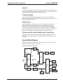
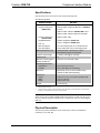
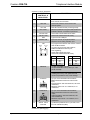
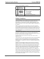
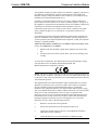
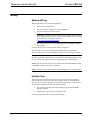
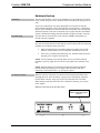
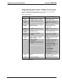
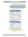
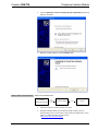
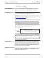
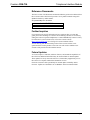
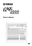
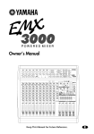
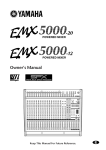
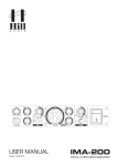
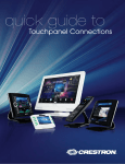
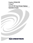
Crestron CEN-TIA
Telephone Interface Module
Operations Guide
This document was prepared and written by the Technical Documentation department at:
Crestron Electronics, Inc.
15 Volvo Drive
Rockleigh, NJ 07647
1-888-CRESTRON
All brand names, product names and trademarks are the property of their respective owners.
©2007 Crestron Electronics, Inc.
Crestron CEN-TIA
Telephone Interface Module
Contents
Telephone Interface Module: CEN-TIA
1
Introduction ............................................................................................................................... 1
Features and Functions ................................................................................................ 1
Internal Block Diagram ............................................................................................... 2
Specifications .............................................................................................................. 3
Physical Description.................................................................................................... 3
Industry Compliance ................................................................................................... 6
Setup .......................................................................................................................................... 8
Network Wiring........................................................................................................... 8
Identity Code ............................................................................................................... 8
Hardware Hookup ....................................................................................................... 9
Programming Software............................................................................................................ 11
Earliest Version Software Requirements for the PC ................................................. 11
Programming with Crestron SystemBuilder.............................................................. 11
Programming with Crestron Toolbox Text Console.................................................. 12
Programming with Crestron Toolbox CEN-TIA Menu Builder................................ 14
Programming with SIMPL Windows ........................................................................ 14
Example Program ...................................................................................................... 17
Uploading and Upgrading........................................................................................................ 18
Establishing Communication..................................................................................... 18
Programs and Firmware ............................................................................................ 20
Program Checks ........................................................................................................ 21
Operation ................................................................................................................................. 22
Problem Solving ...................................................................................................................... 23
Troubleshooting......................................................................................................... 23
Check Network Wiring.............................................................................................. 24
Reference Documents................................................................................................ 25
Further Inquiries ........................................................................................................ 25
Future Updates .......................................................................................................... 25
Return and Warranty Policies .................................................................................................. 26
Merchandise Returns / Repair Service ...................................................................... 26
CRESTRON Limited Warranty................................................................................. 26
Operations Guide – DOC. 6414
Contents • i
Crestron CEN-TIA
Telephone Interface Module
Telephone Interface Module:
CEN-TIA
Introduction
Features and Functions
•
•
•
•
•
•
•
•
•
Remote control access from any phone
Custom door chime, ringer and alarm sounds
Personalized voice prompts
Caller ID (CID)
Telephone paging for multiroom audio systems
Push-To-Talk half-duplex speakerphone
Easy setup via phone and PC software
Microsoft Outlook Address Book import compatibility
Palm database import compatibility
DTMF Control Interface
Use your mobile phone to remotely turn on lights, adjust air conditioning, and
arm/disarm security. Using standard Dual-Tone Multi-Frequency (DTMF) signals,
the CEN-TIA affords telephone keypad control of any automation system function,
providing a prompt-driven user-interface that is simple to use. Configuration
software provided with the CEN-TIA makes it easy to set up a menu of friendly
voice commands using the preloaded voice prompts, or your own custom audio files,
for personalized remote control of your home or office. The CEN-TIA can also dial
out to your mobile phone to alert you to an alarm condition or other system event.
Audio Signal Generator
Loaded with your own custom WAV or MP3 audio files, the CEN-TIA can be used
to generate high-quality door chimes and alarm sounds, and even create unique
telephone ring tones to identify known callers based on Caller ID. With memory
capacity expandable up to 1 GB, the CEN-TIA can easily support several hours of
full-frequency stereo audio files.
Operations Guide – DOC. 6414
Telephone Interface Module: CEN-TIA • 1
Telephone Interface Module
Crestron CEN-TIA
Caller ID
See who is calling before you answer by displaying Caller ID (CID) information on
every touchpanel. Manage missed calls easily with complete caller information and
management options displayed on the touchpanel screen.
Telephone Paging
The CEN-TIA adds telephone paging capability to any Crestron Home® audio
distribution system, allowing sophisticated zone-paging from any telephone to room
speakers throughout the house.
Speakerphone
Enable speakerphone capability on your Crestron® touchpanel. The CEN-TIA
connects directly to a standard phone line, or to your phone system's analog
extension port to provide a single-line, push-to-talk half-duplex speakerphone
interface for any touchpanel with built-in microphone and speakers. Integrated with
the C2N-IADS30x24 Intercom Distribution Switcher, the CEN-TIA can enable
speakerphone capabilities for multiple touchpanels throughout the house.
Outlook and Palm Address Book Import Compatibility
Both Microsoft Outlook Address Book and Palm Desktop Address Book can be
imported into the CEN-TIA. Refer to the Toolbox help file for information on this
procedure.
Internal Block Diagram
The following diagram represents the electrical details of the CEN-TIA. For more
information, refer to “Operation” on page 22.
Internal Block Diagram of the CEN-TIA
CODEC
DAA
LINE OUT
PHONE
OUT
PHONE IN
LINE IN
STEREO
PHONE
LINE
DSP
CROSS
POINT
MP3
LINE OUT
STEREO
FLASH/
SDRAM
RECORD
PLAY
BACK
AUDIO
DAC
AUDIO
CODEC
COLD
FIRE
CRESNET
USB
MP3
DECODER
ETHERNET
MMC/
FLASH
2 • Telephone Interface Module: CEN-TIA
Operations Guide – DOC. 6414
Crestron CEN-TIA
Telephone Interface Module
Specifications
Specifications for the CEN-TIA are listed in the following table.
CEN-TIA Specifications
SPECIFICATION
DETAILS
Audio:
Frequency Response
(AUDIO OUT)
20Hz to 20kHz ±0.5dB from MP3 file or AUDIO IN
sources;
300Hz to 3kHz –3dB from PHONE LINE source;
300Hz to 3kHz –3dB from WAV file messages
Frequency Response
(PHONE LINE)
300Hz to 3kHz –3dB
Signal/Noise Ratio
94 dB A-weighted at AUDIO OUT
THD + N
0.05% A-weighted at AUDIO OUT
MP3 File Support
44.1 kHz sampling rate, 64 to 128 Kb/s bit rate
WAV File Support
8 and 16-bit PCM, mono, 8 kHz sampling rate
Multimedia Memory Card
32 MB included, 1 GB maximum; stores
MenuBuilder program and audio files
Cresnet® Power Usage
7 Watts (0.3 Amp @ 24 Volts DC)
Default Net ID
49
Minimum 2-Series Control
System Update File1, 2
Version 3.155.1143.CUZ or later
Operating Environment
Temperature
Humidity
Enclosure
32° to 122°F (0° to 50°C)
10% to 90% RH (non-condensing)
Black metal, 0.5U 19” rack-mountable using
optional ST-RMK (sold separately)
Dimensions
Height:
Width:
Depth:
Weight
1.
2.
1.80 in (4.57 cm), 1.70 in (4.32 cm) without feet
7.07 in (17.96 cm)
6.36 in (16.15 cm)
1.8 lbs (0.9 kg)
The latest software versions can be obtained from the Crestron website. Refer to the NOTE
following these footnotes.
Crestron 2-Series control systems include the AV2 and PRO2. Consult the latest Crestron Product
Catalog for a complete list of 2-Series control systems.
NOTE: Crestron software and any files on the website are for authorized Crestron
dealers and Crestron Authorized Independent Programmers (CAIP) only. New users
may be required to register to obtain access to certain areas of the site (including the
FTP site).
Physical Description
This section provides information on the connections, controls, and indicators
available on your CEN-TIA.
Operations Guide – DOC. 6414
Telephone Interface Module: CEN-TIA • 3
Telephone Interface Module
Crestron CEN-TIA
CEN-TIA Physical View
CEN-TIA Overall Dimensions
1
2
4
3
5
7
6
7.07 in
(17.96 cm)
6.36 in
(16.15 cm)
8
9
10
11
12
13
14
15
1.80 in
(4.57 cm)
4 • Telephone Interface Module: CEN-TIA
Operations Guide – DOC. 6414
Crestron CEN-TIA
Telephone Interface Module
Connectors, Controls, & Indicators
#
CONNECTORS*,
CONTROLS, &
INDICATORS
DESCRIPTION
1
PWR LED
Green LED indicates 24 Volts DC power supplied
from Cresnet control network.
2
NET LED
Yellow LED indicates communication with
Cresnet System.
3
ACT LED
Red LED indicates internal processing activity.
4
OFF HOOK
5
LAN LNK LED
Green LED indicates Ethernet link status.
6
LAN ACT LED
Yellow LED indicates Ethernet activity.
7
USB
8
PHONE LINE
9
LAN
GREEN
LED
PIN 8
10
YELLOW
LED
Miniature pushbutton and green LED initiates and
indicates “off-hook” connection to phone line.
Type B “female” USB port.
6-pin RJ11 female; for single-line POTS
telephone line or analog extension port.
For programmatic interface with Crestron Toolbox
CEN-TIA Menu Builder.
(1) 8-wire RJ-45 with two LED indicators;
10BaseT/100BaseTX Ethernet port,
auto-negotiating;
Green LED indicates link status;
Yellow LED indicates Ethernet activity
PIN 1
MEMORY
PIN
SIGNAL
PIN
SIGNAL
1
2
3
4
TX +
TX RC+
N/C
5
6
7
8
N/C
RC N/C
N/C
(1) MMC compatible card slot;
Accepts Multimedia memory card up to 1 GB
(32 Mb included)
CAUTION: Install with label facing up only.
Installing the memory card upside down will
render it inoperable and may cause damage.
11
AUDIO IN
12
AUDIO OUT
(1) 5-pin 3.5mm detachable terminal block;
Balanced/unbalanced stereo line-level audio
output;
Output impedance: 200 ohms balanced; 100
ohms unbalanced;
Maximum Output Level: 4 Vrms balaned, 2 Vrms
unbalanced
13
SETUP LED &
BUTTON
(1) Miniature pushbutton and (1) red LED, used
for touch-settable ID (TSID).
(1) 5-pin 3.5mm detachable terminal block;
Balanced/unbalanced stereo line-level audio
input;
Input Impedance: 20k ohms balanced, 10k ohms
unbalanced;
Maximum Input Level: 4Vrms balanced, 2 Vrms
unbalanced
(Continued on following page)
Operations Guide – DOC. 6414
Telephone Interface Module: CEN-TIA • 5
Telephone Interface Module
Crestron CEN-TIA
Connectors, Controls, & Indicators (Continued)
*
#
CONNECTORS*,
CONTROLS, &
INDICATORS
DESCRIPTION
14
NET
Four-position terminal block connector for data
and power. Connects to Cresnet control network.
Pin 1 (24) Power
Pin 2 (Y) Data
Pin 3 (Z) Data
Pin 4 (G) Ground
15
GROUND
(1) 6-32 screw, chassis ground lug
Interface connectors for AUDIO IN, AUDIO OUT, and NET, ports are provided with the unit.
Industry Compliance
NOTE: This equipment meets the applicable Industry Canada Terminal Equipment
Technical Specifications. This is confirmed by the registration number. The
abbreviations, IC, before the registration number signifies that registration was
performed based on a Declaration of Conformity indicating that Industry Canada
technical specifications were met. It does not imply that Industry Canada approved
the equipment.
NOTE: The Ringer Equivalence Number (REN) for this terminal equipment is
0.1A. The REN assigned to each terminal equipment provides an indication of the
maximum number of terminals allowed to be connected to a telephone interface. The
termination on an interface may consist of any combination of devices subject only
to the requirement that the sum of the Ringer Equivalence Numbers of all the devices
does not exceed five.
This equipment complies with Part 68 of the FCC rules and the requirements adopted
by the ACTA. On the bottom of the unit is a label that contains, among other
information, a product identifier in the format US:AAAEQ##TXXXX. If requested,
this number must be provided to the telephone company.
Applicable connector jack Universal Service Order Codes (“USOC”) for the
Equipment is RJ11C.
A plug and jack used to connect this equipment to the premises wiring and telephone
network must comply with the applicable FCC Part 68 rules and requirements
adopted by the ACTA. A compliant telephone cord and modular plug is provided
with this product. It is designed to be connected to a compatible modular jack that is
also compliant.
The REN is used to determine the number of devices that may be connected to a
telephone line. Excessive RENs on a telephone line may result in the devices not
ringing in response to an incoming call. In most but not all areas, the sum of RENs
should not exceed five (5.0). To be certain of the number of devices that may be
connected to a line, as determined by the total RENs, contact the local telephone
company. For products approved after July 23, 2001, the REN for this product is part
of the product identifier that has the format US:AAAEQ##TXXXX. The digits
represented by ## are the REN without a decimal point (e.g., 03 is a REN of 0.3).
If this CEN-TIA causes harm to the telephone network, the telephone company will
notify you in advance that temporary discontinuance of service may be required. But
if advance notice isn't practical, the telephone company will notify the customer as
soon as possible. Also, you will be advised of your right to file a complaint with the
FCC if you believe it is necessary.
6 • Telephone Interface Module: CEN-TIA
Operations Guide – DOC. 6414
Crestron CEN-TIA
Telephone Interface Module
The telephone company may make changes in its facilities, equipment, operations or
procedures that could affect the operation of the equipment. If this happens the
telephone company will provide advance notice in order for you to make necessary
modifications to maintain uninterrupted service.
If trouble is experienced with this CEN-TIA, for repair or warranty information,
please contact Crestron customer service (refer to “Further Inquiries” on page 25. If
the equipment is causing harm to the telephone network, the telephone company may
request that you disconnect the equipment until the problem is resolved.
Connection to party line service is subject to state tariffs. Contact the state public
utility commission, public service commission or corporation commission for
information.
If your home has specially wired alarm equipment connected to the telephone line,
ensure the installation of this equipment does not disable your alarm equipment. If
you have questions about what will disable alarm equipment, consult your telephone
company or a qualified installer.
WHEN PROGRAMMING EMERGENCY NUMBERS AND(OR) MAKING TEST
CALLS TO EMERGENCY NUMBERS:
3.
Remain on the line and briefly explain to the dispatcher the reason for the
call.
4.
Perform such activities in the off-peak hours, such as early morning or late
evenings.
As of the date of manufacture, the CEN-TIA has been tested and found to comply
with specifications for CE marking and standards per EMC and
Radiocommunications Compliance Labelling.
NOTE: This device complies with part 15 of the FCC rules. Operation is subject to
the following two conditions: (1) this device may not cause harmful interference, and
(2) this device must accept any interference received, including interference that may
cause undesired operation.
This equipment has been tested and found to comply with the limits for a Class B
digital device, pursuant to part 15 of the FCC Rules. These limits are designed to
provide reasonable protection against harmful interference in a residential
installation. This equipment generates, uses and can radiate radio frequency energy
and, if not installed and used in accordance with the instructions, may cause harmful
interference to radio communications. However, there is no guarantee that
interference will not occur in a particular installation. If this equipment does cause
harmful interference to radio or television reception, which can be determined by
turning the equipment off and on, the user is encouraged to try to correct the
interference by one or more of the following measures:
Reorient or relocate the receiving antenna.
Increase the separation between the equipment and receiver.
Connect the equipment into an outlet on a circuit different from that to
which the receiver is connected.
Consult the dealer or an experienced radio/TV technician for help.
Operations Guide – DOC. 6414
Telephone Interface Module: CEN-TIA • 7
Telephone Interface Module
Crestron CEN-TIA
Setup
Network Wiring
When wiring the network, consider the following:
•
Use Crestron Certified Wire.
•
Use Crestron power supplies for Crestron equipment.
•
Provide sufficient power to the system.
CAUTION: Insufficient power can lead to unpredictable results or damage
to the equipment. Please use the Crestron Power Calculator to help calculate
how much power is needed for the system
(http://www.crestron.com/calculators).
•
For larger networks, Use a Cresnet Hub/Repeater (CNXHUB) to maintain
signal quality
For more details, refer to “Check Network Wiring” on page 24.
The CEN-TIA uses Cresnet, USB and high-speed Ethernet for programmatic
interface with Crestron’s Toolbox application. Please refer to the Toolbox help file.
NOTE: The CEN-TIA is shipped with DHCP enabled (no default IP address). If it is
desirable to manually set the IP address of the CEN-TIA (DHCP disabled) by using
the Text Console in Toolbox. Refer to the Toolbox help file for further details.
NOTE: The CEN-TIA can only be set up with the CEN-TIA Menu Builder tool that
is included in Toolbox version 1.04.13 and later.
NOTE: The Ethernet port on the CEN-TIA does not support Voice Over IP (VOIP).
Identity Code
The Net ID of the CEN-TIA has been factory set to 49. The Net IDs of multiple
CEN-TIA devices in the same system must be unique if they are connected to the
same Cresnet. Net IDs are changed from a personal computer (PC) via the Crestron
Toolbox. When setting the Net ID, consider the following:
•
The Net ID of each unit must match an ID code specified in the SIMPL
Windows program.
•
Each network device must have a unique Net ID.
For more details, refer to the Crestron Toolbox help file.
8 • Telephone Interface Module: CEN-TIA
Operations Guide – DOC. 6414
Crestron CEN-TIA
Telephone Interface Module
Hardware Hookup
Ventilation
The CEN-TIA should be used in a well-ventilated area. If the CEN-TIA is hot to the
touch, consider using forced air ventilation and/or incrementing the spacing between
units.
To prevent overheating, do not operate this product in an area that exceeds the
environmental temperature range listed in the table of specifications. Consideration
must be given if installed in a closed or multi-unit rack assembly since the operating
ambient temperature of the rack environment may be greater than the room ambient.
Contact with thermal insulating materials should be avoided on all sides of the unit.
Rack Mounting
The CEN-TIA can be mounted in a rack with the ST-RMK (sold separately) or
stacked with other equipment.
WARNING: To prevent bodily injury when mounting or servicing this unit in a
rack, take special precautions to ensure that the system remains stable. The following
guidelines are provided to ensure your safety:
•
When mounting this unit in a partially filled rack, load the rack from the
bottom to the top with the heaviest component at the bottom of the rack.
•
If the rack is provided with stabilizing devices, install the stabilizers before
mounting or servicing the unit in the rack.
NOTE: If rack mounting is not required, rubber feet are provided for tabletop
mounting or stacking. Apply the feet near the corner edges on the underside of the
unit.
NOTE: Reliable earthing of rack-mounted equipment should be maintained.
Particular attention should be given to supply connections other than direct
connections to the branch circuit. (e.g., use of power strips).
Connect the Device
Make the necessary connections as called out in the illustration that follows this
paragraph. Refer to “Network Wiring” on page 8 before attaching the 4-position
terminal block connector. Apply power after all connections have been made.
When making connections to the CEN-TIA, consider the following, use Crestron
power supplies.
Hardware Connections for the CEN-TIA (Front)
CONSOLE INTERFACE:
SERIAL COMMUNICATION
WITH PC
Operations Guide – DOC. 6414
Telephone Interface Module: CEN-TIA • 9
Telephone Interface Module
Crestron CEN-TIA
Hardware Connections for the CEN-TIA (Rear)
MEMORY:
MMC CARD
SLOT
PHONE LINE
LAN:
10 BaseT/100 BaseTX
HIGH SPEED
ETHERNET TO LAN
AUDIO OUTPUT:
BALANCED AND UNBALANCED AUDIO
SIGNALS TO AMP, ETC.
AUDIO INPUT:
BALANCED AND UNBALANCED AUDIO
SIGNALS FROM LOCAL AUDIO SOURCES
GROUND
NET:
TO CONTROL
SYSTEM AND OTHER
CRESNET DEVICES
The CEN-TIA’s audio connections support both balanced and unbalanced line-level
audio. These connectors are wired as shown in the following illustrations.
Audio Input: Balanced and Unbalanced
L
R
L
+-G+-
R
+-G+-
Shield
+
Left
+
Jumpers
Shield
+
+
Right
Shield
Audio Output: Balanced and Unbalanced
L
R
L
+-G+-
R
+-G+Shield
+
+
+
10 • Telephone Interface Module: CEN-TIA
Right
Shield
Right
AMP
Shield
AMP
Left
+
Left
Operations Guide – DOC. 6414
Crestron CEN-TIA
Telephone Interface Module
Programming Software
Have a question or comment about Crestron software?
Answers to frequently asked questions (FAQs) can be viewed in the Online Help
section of the Crestron website. To post a question or view questions you have
submitted to Crestron’s True Blue Support, log in at http://support.crestron.com.
First-time users will need to establish a user account.
Earliest Version Software Requirements for the PC
NOTE: Crestron recommends that you use the latest software to take advantage of
the most recently released features. The latest software is available from the Crestron
website.
Crestron has developed an assortment of Windows®-based software tools to develop
a Cresnet system. The following are the minimum recommended software versions
for the PC:
Software
TASK
REQUIRED SOFTWARE VERSION
Program control system to
operate CEN-TIA.
SIMPL Windows version 2.07.15 or later
with SIMPL+ Cross Compiler version 1.1 or
later and Library Update 444 or later.
Upload program and firmware,
configure internal menus, events
and commands.
Crestron Toolbox 1.04.13 or later with the
CEN-TIA Menu Builder tool.
Program with simple wizards for
systems using a CEN-TIA
(optional but recommended).
Crestron SystemBuilder™ version 3.0.18 or
later (requires SIMPL Windows,
VisionTools Pro-e, Crestron Database
18.4.3 and Crestron Engraver) with
SystemBuilder Templates version 3.2.0 or
later. Refer to software release notes or
Crestron website for other required
Crestron software packages.
Programming with Crestron SystemBuilder
Crestron SystemBuilder is the easiest method of programming but does not offer as
much flexibility as SIMPL Windows. For additional details, download
SystemBuilder from the Crestron website and examine the extensive help file.
Operations Guide – DOC. 6414
Telephone Interface Module: CEN-TIA • 11
Telephone Interface Module
Crestron CEN-TIA
Programming with Crestron Toolbox Text Console
There are a number of commands that can only be executed at the command line
interface provided by the Crestron Toolbox Text Console.
Text Console Commands
COMMAND
COMMAND SYNTAX
DESCRIPTION
ADDRBOOK
ADD
ADDRBOOK ADD <First Name>
<Last Name> <Phone Number>
Adds a record or person to the
internal address book.
ADDRBOOK
BRIEF
ADDRBOOK BRIEF <SortField>
Displays a list of records in the
address book sorted by last
name.
ADDRBOOK
IMPORT
ADDRBOOK IMPORT <Outlook |
Palm> <Filename>
Allows you to import a
Microsoft Outlook or Palm
address book.
ADDRBOOK
DELETE
ADDRBOOK DELETE <Index>
Deletes the address book or
record.
ADDRBOOK
SAVE
ADDRBOOK SAVE
Saves the address book.
ADDRBOOK
VERBOSE
ADDRBOOK VERBOSE
<Sortfield>
Displays all of the fields for
every record in the address
book.
EMAIL
EMAIL <filename> <recipient>
<server> <from>
Allows you to email a file from
the CEN-TIA.
MIXER
MIXER <channel|*>
[LEFT|RIGHT]
<VOL|MUTE|BASS|TREBLE|BAL
> <value>
The MIXER command alone
will display the status of the
CEN-TIA internal mixer.
The numerical values for
Left/Right Volume, Bass and
Treble are 0 thru 65535.
Channels are:
(2) MP3 Playback
(2) WAV Playback
(2) WAV Record
Mute values are 0 (mute off)
and 1 (mute on).
ESTAT
ESTAT
Displays the status of active
network connections.
PAUSE
PAUSE [PLAYERID]
Pauses playback of an audio
file.
(Continued on following page)
12 • Telephone Interface Module: CEN-TIA
Operations Guide – DOC. 6414
Crestron CEN-TIA
Telephone Interface Module
Text Console Commands (Continued)
COMMAND
COMMAND SYNTAX
DESCRIPTION
PHONE
PHONE
<ANSWER|HANGUP|STATUS>
Performs telephone
operations.
PHONE DIAL <DIGITS>
Digits may be: 1234567890*#
PHONE DTMF <DIGIT> [MSEC]
Digits may be: 1234567890*#
MSEC: 0 to 65535
PHONE COUNTRY
<COUNTRY> <MODE>
Where COUNTRY is one of
the following:
CUSTOM, AUSTRALIA,
BULGARIA, CHINA, CTR21,
CZECH_REPUBLIC, FCC,
HUNGARY, JAPAN,
MALAYSIA, NEW_ZEALAND,
PHILIPPINES, POLAND,
SINGAPORE, SLOVAKIA,
SLOVENIA, SOUTH_AFRICA,
SOUTH_KOREA
MODE (current line monitor):
[LOW|HIGH]
NOTE: Only use the following
command if one of the above
country settings does not work!
PHONE DAA <MODE> <OHS>
<ACT> <DCT> <RZ> <RT>
<LIM> <VOL>
MODE (current line monitor):
[LOW|HIGH]
OHS (on-hook speed):
[FAST|SLOW]
ACT: (AC termination):
[REAL|COMPLEX] impedance
DCT: (DC termination): [LOWVOLTAGE|JAPAN|FCC|CTR2
1]
RZ: (ringer impedance):
[MAX|SYNTHESIZE]
RT: (ringer threshold select):
[11|17] Vrms
LIM: (current limit):
[CTR21|OTHER]
VOL: (line voltage adjust):
[NORMAL|LOWER]
PLAY
PLAY <NAME> [NOWAIT]
Plays an audio file.
RECORD
RECORD [<RECORDERID>]
<FILENAME>
Records an audio file.
RECORDERID parameter is
optional.
RESUME
RESUME [PLAYERID]
Resumes playback of an audio
file.
RPAUSE
RPAUSE [RECORDERID]
Pauses recording an audio file.
RRES
RESUME [RECORDERID]
Resumes recording an audio
file.
(Continued on following page)
Operations Guide – DOC. 6414
Telephone Interface Module: CEN-TIA • 13
Telephone Interface Module
Crestron CEN-TIA
Text Console Commands (Continued)
COMMAND
COMMAND SYNTAX
DESCRIPTION
RSTOP
RSTOP [<RECORDERID>]
Stops recording an audio file.
SCRIPT
SCRIPT <FILENAME>
Runs the specified script.
STOP
STOP [<PLAYERID>]
Stop playing an audio file.
STOP <PLAYERNAME>
Audio Players:
(0) MP3
(1) WAV
XPOINT
XPOINT CONN <IN> <OUT>
[NOSAVE]
Display/make/break crosspoint
connections.
XPOINT DISC <IN> <OUT>
[NOSAVE]
Inputs:
0: NONE
1: LINEL
2: LINER
3: MP3L
4: MP3R
5: WAVE
6: PHONE
Outputs:
0: LINEL
1: LINER
2: PHONE
3: REC
Programming with Crestron Toolbox CEN-TIA
Menu Builder
The CEN-TIA Menu Builder tool in Toolbox is required to set up the internal menus,
events and commands that determine how the CEN-TIA responds to your telephone
system (i.e., incoming calls, DTMF inputs from a telephone handset, touchpanel
inputs, etc.). For details about using the CEN-TIA Menu Builder tool, refer to the
Toolbox help file.
Programming with SIMPL Windows
NOTE: While SIMPL Windows can be used to program the CEN-TIA as it relates
to a Crestron network with a control system, it is recommended to use the Toolbox
CEN-TIA Menu Builder for configuring the device.
SIMPL Windows is Crestron’s premier software for programming Crestron control
systems. It is organized into two separate, but equally important “Managers”.
Configuration Manager
Configuration Manager is the view where programmers “build” a Crestron control
system by selecting hardware from the Device Library.
NOTE: The CEN-TIA can be used as both a Cresnet and Ethernet device. As a
Cresnet device, it can simply be added to an appropriate control system such as the
PRO2. As an Ethernet device, it must be added after an Ethernet card such as the
C2ENET-1 is configured into the system.
14 • Telephone Interface Module: CEN-TIA
Operations Guide – DOC. 6414
Crestron CEN-TIA
Telephone Interface Module
•
To incorporate the CEN-TIA into the system as an Ethernet device, drag the
CEN-TIA (Ethernet) from the Ethernet Control Modules | Ethernet Audio
Modules folder of the Device Library and drop it in the System Views.
Locating the Ethernet CEN-TIA in the Device Library
•
To incorporate the CEN-TIA into the system as a Cresnet device, drag the
CEN-TIA (Cresnet) from the Cresnet Control Modules | Cresnet Audio
Modules folder of the Device Library and drop it in the System Views.
Locating the Cresnet CEN-TIA in the Device Library
•
The system tree of the control system displays the devices in their
appropriate slots with default IP ID or Net ID as shown in the following
illustration.
C2ENET-1 and C2Net Devices, Slots 8 and 9
Operations Guide – DOC. 6414
Telephone Interface Module: CEN-TIA • 15
Telephone Interface Module
•
Crestron CEN-TIA
The initial Cresnet CEN-TIA will take ID 49. Additional Cresnet
CEN-TIA devices would be assigned the lowest legal unused Cresnet ID
(e.g., 03 if unused). The initial Ethernet CEN-TIA will take IP ID 03. If an
additional Ethernet CEN-TIA is added the IP ID of that unit would be 04.
NOTE: In the case of the Ethernet CEN-TIA, the IP ID must match the IP ID in the
IP table.
•
If necessary, double click a device to open the “Device Settings” window
and change the IP ID or Net ID, as shown in the following figures.
“CEN-TIA Device Settings-Ethernet” Window
“CEN-TIA Device Settings-Cresnet” Window
•
The ID code specified in the SIMPL Windows program must match the IP
ID or Net ID of each unit.
16 • Telephone Interface Module: CEN-TIA
Operations Guide – DOC. 6414
Crestron CEN-TIA
Programming Manager
Telephone Interface Module
Programming Manager is the view where programmers "program" a Crestron control
system by assigning signals to symbols. The symbol can be viewed by double
clicking on the icon or dragging it into Detail View. A description of the CEN-TIA
symbol and for each signal in the symbol is described in the SIMPL Windows help
file (F1).
Example Program
An example program for the CEN-TIA is available from the “Example Program”
section of the Crestron website (http://www.crestron.com/exampleprograms).
Operations Guide – DOC. 6414
Telephone Interface Module: CEN-TIA • 17
Telephone Interface Module
Crestron CEN-TIA
Uploading and Upgrading
Crestron recommends using the latest programming software and that each device
contains the latest firmware to take advantage of the most recently released features.
However, before attempting to upload or upgrade, it is necessary to establish
communication. Once communication has been established, files (for example,
programs or firmware) can be transferred to the control system (and/or device).
Finally, program checks can be performed (such as changing the device ID or
creating an IP table) to ensure proper functioning.
Establishing Communication
Use Crestron Toolbox for communicating with the CEN-TIA. Refer to the Crestron
Toolbox help file for details. There are three methods of communication.
Direct Serial Communication
Direct USB Communication
PC RUNNING
CRESTRON TOOLBOX
SERIAL
USB
CEN-TIA
•
CEN-TIA connects to PC running Toolbox via the USB port. Note that
Cresnet power must still be applied.
•
Establish communication between the PC and the CEN-TIA. The first time
communication is established, Windows will launch the Found New
Hardware Wizard.
•
Click the No, not this time radio button and then click Next.
18 • Telephone Interface Module: CEN-TIA
Operations Guide – DOC. 6414
Crestron CEN-TIA
Indirect Serial Communication
Telephone Interface Module
•
Click the Install the software automatically (Recommended) radio button
and then click Next.
•
When the wizard completes, click the Finish button.
Indirect Serial Communication
PC RUNNING
CRESTRON TOOLBOX
Operations Guide – DOC. 6414
SERIAL,
ETHERNET
OR USB
CONTROL SYSTEM
CRESNET
CEN-TIA
•
CEN-TIA connects to control system via Cresnet.
•
Establish communications between the PC and the control system as
described in the latest version of the 2-Series Reference Guide (Doc. 6256)
which is available from the Crestron website
(http://www.crestron.com/manuals).
Telephone Interface Module: CEN-TIA • 19
Telephone Interface Module
TCP/IP Communication
Crestron CEN-TIA
Ethernet Communication
PC RUNNING
CRESTRON TOOLBOX
CEN-TIA
ETHERNET
•
Establish direct USB communication between CEN-TIA and PC.
•
DHCP is enabled by default on the CEN-TIA. If you have to disable it and
manually establish an IP address, do so using Crestron Toolbox
(Functions | Ethernet Addressing).
•
Confirm Ethernet connections between CEN-TIA and PC. If connecting
through a hub or router, use CAT5 straight through cables with 8-pin RJ-45
connectors. Alternatively, Use a CAT5 crossover cable to connect the two
LAN ports directly, without using a hub or router.
•
Use the Address Book in the Crestron Toolbox to create an entry for the
CEN-TIA with the CEN-TIA’s TCP/IP communication parameters.
•
Display the “System Info” window (click the
CEN-TIA entry.
•
Use the Crestron Toolbox to create the CEN-TIA IP table.
icon) and select the
⇒ Select Functions | IP Table Setup.
⇒ Either add, modify, or delete entries in the IP table. The CEN-TIA
can have only one IP table entry.
⇒ A defined IP table can be saved to a file or sent to the device.
•
Edit the control system’s IP table to include an entry for the CEN-TIA. The
entry should list the CEN-TIA’s IP ID (specified on the CEN-TIA’s IP
table) and the internal gateway IP address 127.0.0.1.
Programs and Firmware
Program or firmware files may be distributed from programmers to installers or from
Crestron to dealers. Firmware upgrades are available from the Crestron website as
new features are developed after product releases. One has the option to upload
programs and projects via the programming software or to upload and upgrade via
the Crestron Toolbox. For details on uploading and upgrading, refer to the SIMPL
Windows help file or the Crestron Toolbox help file.
SIMPL Windows
If a SIMPL Windows program is provided, it can be uploaded to the control system
using SIMPL Windows or Crestron Toolbox.
CEN-TIA Menu Builder
If a CEN-TIA Menu Builder Project is provided or created, it can be uploaded to the
device using the CEN-TIA Menu Builder tool in Crestron Toolbox.
Firmware
Check the Crestron website to find the latest firmware. (New users may be required
to register to obtain access to certain areas of the site, including the FTP site.)
Upgrade CEN-TIA firmware via Crestron Toolbox.
•
Establish serial or TCP/IP communications with the CEN-TIA and display
the “System Info” window.
•
Select Functions | Firmware… to upgrade the CEN-TIA firmware.
20 • Telephone Interface Module: CEN-TIA
Operations Guide – DOC. 6414
Crestron CEN-TIA
Telephone Interface Module
Program Checks
Actions that can be performed on the CEN-TIA vary depending on whether it is
connected via Cresnet or Ethernet.
Cresnet Connections
Ethernet Connections
For Cresnet connections, using Crestron Toolbox, display the network device tree
(Tools | Network Device Tree) to show all network devices connected to the control
system. Right-click on the CEN-TIA to display actions that can be performed on the
CEN-TIA.
For Ethernet connections, display the “System Info window (click the
icon) and
select the Functions menu to display actions that can be performed on the CEN-TIA.
Be sure to use the Crestron Toolbox to create the CEN-TIA IP table.
•
Select Functions | IP Table Setup.
•
Add, modify or delete entries in the IP table. The CEN-TIA can have only
one IP table entry.
•
A defined IP table can be saved to a file or sent to the device.
Edit the control system’s IP table to include an entry for the CEN-TIA. The entry
should list the CEN-TIA’s IP ID (specified on the CEN-TIA’s IP table) and the
internal gateway IP address 127.0.0.1.
Operations Guide – DOC. 6414
Telephone Interface Module: CEN-TIA • 21
Telephone Interface Module
Crestron CEN-TIA
Operation
The CEN-TIA uses audio messages as voice prompts and responses. These files can
be WAV or MP3 files. Pre-recorded message files can be downloaded from
Crestron’s website (ftp://ftp.crestron.com).
A Cresnet system with the CEN-TIA may be programmed to respond to incoming
telephone tones or a sequence of tones. For example, pressing 1 from a telephone
(after connecting to the system) may be used to activate an air conditioning system
and the CEN-TIA would respond with “Command accepted, air conditioning is on”.
The system may also be programmed to dial-out and play a recorded message when
a specific input, such as from a security system, is received. By using CID
information, the system can be programmed to allow access from only a specific
telephone to perform various functions or play customized greetings depending on
the number calling.
Refer to the Toolbox help file for details on setting up the CEN-TIA to perform these
and many other functions.
22 • Telephone Interface Module: CEN-TIA
Operations Guide – DOC. 6414
Crestron CEN-TIA
Telephone Interface Module
Problem Solving
Troubleshooting
The following table provides corrective action for possible trouble situations. If
further assistance is required, please contact a Crestron customer service
representative.
CEN-TIA Troubleshooting
TROUBLE
POSSIBLE CAUSE(S)
CORRECTIVE ACTION
Device is not
communicating with the
network.
Use Crestron Toolbox to poll
the network. Verify network
connection to the device.
Device is not receiving
power from a Crestron
power source.
Use the provided Crestron
power source. Verify
connections.
Device is not receiving
sufficient power.
Use the Crestron Power
Calculator to help calculate
how much power is needed
for the system.
Device Net ID or IP ID
does not match control
system ID setting.
Use Crestron Toolbox or
SIMPL to change the Net ID
or IP ID.
Control system not
configured properly.
Determine correct control
system configuration and
make appropriate changes.
USB connection
stops responding.
USB connection
terminated without first
stopping the USB driver.
Right click on the Safely
Remove Hardware icon in the
System Tray.
Select Generic Crestron
Console V2 device and click
the stop button.
Reconnect via Toolbox using
the USB connection.
Audio output is
distorted.
Mixer settings and/or
audio source levels are
too high.
Reduce audio output levels
until distortion disappears.
Device does not
perform the tasks
programmed
using CEN-TIA
Menu Builder tool.
Correct CEN-TIA Menu
Builder project file not
loaded or incorrectly
configured.
Check the CEN-TIA Menu
Builder project file and make
necessary changes. Upload
correct file if necessary.
CEN-TIA functions
properly but
feedback
indicator(s) do(es)
not illuminate.
Feedback signal names
incorrect in SIMPL
Windows program.
Verify SIMPL Windows
program for feedback signal
names.
Device does not
function.
Operations Guide – DOC. 6414
Telephone Interface Module: CEN-TIA • 23
Telephone Interface Module
Crestron CEN-TIA
Check Network Wiring
Use the Right Wire
Calculate Power
In order to ensure optimum performance over the full range of your installation
topology, Crestron Certified Wire, and only Crestron Certified Wire, may be used.
Failure to do so may incur additional charges if support is required to identify
performance deficiencies because of using improper wire.
CAUTION: Use only Crestron power supplies for Crestron equipment. Failure to do
so could cause equipment damage or void the Crestron warranty.
CAUTION: Provide sufficient power to the system. Insufficient power can lead to
unpredictable results or damage to the equipment. Please use the Crestron Power
Calculator to help calculate how much power is needed for the system
(http://www.crestron.com/calculators).
When calculating the length of wire for a particular Cresnet run, the wire gauge and
the Cresnet power usage of each network unit to be connected must be taken into
consideration. Use Crestron Certified Wire only. If Cresnet units are to be daisychained on the run, the Cresnet power usage of each network unit to be daisy-chained
must be added together to determine the Cresnet power usage of the entire chain. If
the unit is a home-run from a Crestron system power supply network port, the Cresnet
power usage of that unit is the Cresnet power usage of the entire run. The wire gauge
and the Cresnet power usage of the run should be used in the following equation to
calculate the cable length value on the equation’s left side.
Cable Length Equation
L<
40,000
RxP
Where: L = Length of run (or chain) in feet
R = 6 Ohms (Crestron Certified Wire: 18 AWG (0.75 MM 2 ))
or 1.6 Ohms (Cresnet HP: 12 AWG (4 MM 2 ))
P = Cresnet power usage of entire run (or chain)
Make sure the cable length value is less than the value calculated on the right side of
the equation. For example, a Cresnet run using 18 AWG Crestron Certified Wire and
drawing 20 watts should not have a length of run more than 333 feet. If Cresnet HP is
used for the same run, its length could extend to 1250 feet.
NOTE: All Crestron certified Cresnet wiring must consist of two twisted pairs. One
twisted pair is the +24V conductor and the GND conductor, and the other twisted pair
is the Y conductor and the Z conductor.
Strip and Tin Wire
When daisy-chaining Cresnet units, strip the ends of the wires carefully to avoid
nicking the conductors. Twist together the ends of the wires that share a pin on the
network connector, and tin the twisted connection. Apply solder only to the ends of
the twisted wires. Avoid tinning too far up the wires or the end becomes brittle. Insert
the tinned connection into the Cresnet connector and tighten the retaining screw.
Repeat the procedure for the other three conductors.
Add Hubs
For larger networks (i.e., greater than 28 network devices), it may become necessary
to add a Cresnet Hub/Repeater (CNXHUB) to maintain signal quality throughout the
network. Also, for networks with lengthy cable runs, it may be necessary to add a
Hub/Repeater after only 20 devices.
24 • Telephone Interface Module: CEN-TIA
Operations Guide – DOC. 6414
Crestron CEN-TIA
Telephone Interface Module
Reference Documents
The latest version of all documents mentioned within the guide can be obtained from
the Crestron website. This link will provide a list of product manuals arranged in
alphabetical order by model number.
List of Related Reference Documents
DOCUMENT TITLE
2-Series Control Systems Reference Guide
Further Inquiries
If you cannot locate specific information or have questions after reviewing this
guide, please take advantage of Crestron's award winning customer service team by
calling the Crestron corporate headquarters at 1-888-CRESTRON [1-888-273-7876].
For assistance in your local time zone, refer to the Crestron website
(http://www.crestron.com/) for a listing of Crestron worldwide offices.
You can also log onto the online help section of the Crestron website to ask
questions about Crestron products. First-time users will need to establish a user
account to fully benefit from all available features.
Future Updates
As Crestron improves functions, adds new features, and extends the capabilities of
the CEN-TIA, additional information may be made available as manual updates.
These updates are solely electronic and serve as intermediary supplements prior to
the release of a complete technical documentation revision.
Check the Crestron website periodically for manual update availability and its
relevance. Updates are identified as an “Addendum” in the Download column.
Operations Guide – DOC. 6414
Telephone Interface Module: CEN-TIA • 25
Telephone Interface Module
Crestron CEN-TIA
Return and Warranty Policies
Merchandise Returns / Repair Service
1.
No merchandise may be returned for credit, exchange, or service without prior authorization
from CRESTRON. To obtain warranty service for CRESTRON products, contact an
authorized CRESTRON dealer. Only authorized CRESTRON dealers may contact the factory
and request an RMA (Return Merchandise Authorization) number. Enclose a note specifying
the nature of the problem, name and phone number of contact person, RMA number, and
return address.
2.
Products may be returned for credit, exchange, or service with a CRESTRON Return
Merchandise Authorization (RMA) number. Authorized returns must be shipped freight
prepaid to CRESTRON, 6 Volvo Drive, Rockleigh, N.J. or its authorized subsidiaries, with
RMA number clearly marked on the outside of all cartons. Shipments arriving freight collect
or without an RMA number shall be subject to refusal. CRESTRON reserves the right in its
sole and absolute discretion to charge a 15% restocking fee, plus shipping costs, on any
products returned with an RMA.
3.
Return freight charges following repair of items under warranty shall be paid by CRESTRON,
shipping by standard ground carrier. In the event repairs are found to be non-warranty, return
freight costs shall be paid by the purchaser.
CRESTRON Limited Warranty
CRESTRON ELECTRONICS, Inc. warrants its products to be free from manufacturing defects in materials
and workmanship under normal use for a period of three (3) years from the date of purchase from
CRESTRON, with the following exceptions: disk drives and any other moving or rotating mechanical
parts, pan/tilt heads and power supplies are covered for a period of one (1) year; touchscreen display and
overlay components are covered for 90 days; batteries and incandescent lamps are not covered.
This warranty extends to products purchased directly from CRESTRON or an authorized CRESTRON
dealer. Purchasers should inquire of the dealer regarding the nature and extent of the dealer's warranty, if
any.
CRESTRON shall not be liable to honor the terms of this warranty if the product has been used in any
application other than that for which it was intended, or if it has been subjected to misuse, accidental
damage, modification, or improper installation procedures. Furthermore, this warranty does not cover any
product that has had the serial number altered, defaced, or removed.
This warranty shall be the sole and exclusive remedy to the original purchaser. In no event shall
CRESTRON be liable for incidental or consequential damages of any kind (property or economic damages
inclusive) arising from the sale or use of this equipment. CRESTRON is not liable for any claim made by a
third party or made by the purchaser for a third party.
CRESTRON shall, at its option, repair or replace any product found defective, without charge for parts or
labor. Repaired or replaced equipment and parts supplied under this warranty shall be covered only by the
unexpired portion of the warranty.
Except as expressly set forth in this warranty, CRESTRON makes no other warranties, expressed or
implied, nor authorizes any other party to offer any warranty, including any implied warranties of
merchantability or fitness for a particular purpose. Any implied warranties that may be imposed by law are
limited to the terms of this limited warranty. This warranty statement supersedes all previous warranties.
Trademark Information
All brand names, product names, and trademarks are the sole property of their respective owners. Windows is a registered trademark
of Microsoft Corporation. Windows95/98/Me/XP and WindowsNT/2000 are trademarks of Microsoft Corporation.
26 • Telephone Interface Module: CEN-TIA
Operations Guide – DOC. 6414
Crestron CEN-TIA
Telephone Interface Module
This page is intentionally left blank.
Operations Guide – DOC. 6414
Telephone Interface Module: CEN-TIA • 27
Crestron Electronics, Inc.
15 Volvo Drive Rockleigh, NJ 07647
Tel: 888.CRESTRON
Fax: 201.767.7576
www.crestron.com
Operations Guide – DOC. 6414
(2013860)
01.07
Specifications subject to
change without notice.