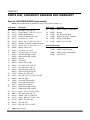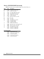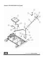
1
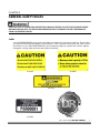
DR® POWER GRADER
SAFETY & OPERATING INSTRUCTIONS
READ AND UNDERSTAND THIS MANUAL AND ALL INSTRUCTIONS
BEFORE OPERATING THIS GRADER.
Congratulations on your purchase of a new DR POWER GRADER!
We have done our utmost to ensure that your DR POWER GRADER will be one of the most trouble-free and
satisfying pieces of equipment you have ever owned. Please let us know of any questions you may have. We
want to answer them as quickly as possible. When you do call, please have your serial number or order
number handy. For technical assistance, please call Toll-Free 1-800-DR-OWNER (376-9637) and one of our
Technical Support Representatives will be happy to help you. We also hope to hear from you on how much
you like your new helper.
In addition, please tell your friends about your new DR POWER GRADER! Having DR Owners spread the
word about our products and our way of doing business is the best advertising we can have, and the best way
to help us provide even better service in the years to come.
Thanks once again!
for all of us at
Country Home Products, Inc.
SALES MANAGER
COPYRIGHT
©2007 Country Home Products, Inc. All rights reserved.
DR® Power Equipment
A division of Country Home Products®
127 Meigs Road
Vergennes, VT 05491
Toll-Free phone: 1-800-DR-OWNER (376-9637)
Fax: 1-802-877-1213
Web site: www.dr-owner.com
ii
DR® POWER GRADER
Table of Contents
CHAPTER 1............................................................................................................................. 1
INTRODUCING THE DR POWER GRADER .................................................................. 1
Conventions used in this manual ................................................................................... 1
CHAPTER 2............................................................................................................................. 3
GENERAL SAFETY RULES............................................................................................... 3
Labels ............................................................................................................................... 3
Protecting Yourself and Those Around You ................................................................... 4
Operating the DR POWER GRADER Safely .................................................................... 4
Safety for Children ........................................................................................................... 5
Safety with Electric-Powered Machines .......................................................................... 5
Handling the Battery Safely ............................................................................................. 6
Safely Charging the Battery ............................................................................................. 6
Additional Information and Potential Changes.............................................................. 7
CHAPTER 3............................................................................................................................. 9
SETTING UP YOUR DR POWER GRADER..................................................................... 9
DR POWER GRADER Controls and Features ................................................................. 9
Unpacking the DR POWER GRADER............................................................................ 10
Parts Checklist ............................................................................................................... 11
Assembling the DR POWER GRADER .......................................................................... 13
Installing the Battery/Clevis Base Assembly and Linear Actuator ............................... 13
Attaching the Yoke......................................................................................................... 15
Charging the Battery ...................................................................................................... 16
About the Battery ........................................................................................................... 16
Linking the Transmitter and Receiver ........................................................................... 18
Replacing the Transmitter Battery................................................................................. 18
Installing the Scarifying Teeth Plate.............................................................................. 19
Connecting the DR POWER GRADER to your Tow Vehicle ......................................... 20
CHAPTER 4........................................................................................................................... 21
OPERATING YOUR DR POWER GRADER ................................................................... 21
Operating Safety ............................................................................................................ 21
Understanding the Height Adjustment Remote Control Transmitter......................... 21
Operating Parameters ................................................................................................... 22
Operating Tips ............................................................................................................... 23
FAQs............................................................................................................................... 24
Optional Drag Screen .................................................................................................... 24
CHAPTER 5........................................................................................................................... 25
MAINTAINING THE DR POWER GRADER ................................................................. 25
Regular Maintenance Check:......................................................................................... 25
Caring for the Battery..................................................................................................... 26
Recycling a Used Battery ............................................................................................... 26
Replacing the Scarifying Teeth Plate ............................................................................. 27
Lubrication ..................................................................................................................... 28
End of Season and Storage ........................................................................................... 28
CHAPTER 6........................................................................................................................... 29
TROUBLESHOOTING................................................................................................... 29
Troubleshooting Table................................................................................................... 29
CALL TOLL-FREE 1-800-DR-OWNER
iii
CHAPTER 7........................................................................................................................... 30
PARTS LIST, SCHEMATIC DIAGRAM AND WARRANTY ............................................ 30
Parts List - DR POWER GRADER Frame Assembly...................................................... 30
Schematic - DR POWER GRADER Frame Assembly .................................................... 31
Parts List - DR POWER GRADER Yoke Assembly ........................................................ 32
Schematic - DR POWER GRADER Yoke Assembly....................................................... 33
Parts List - DR POWER GRADER Optional Drag Screen (Kit No. 210861)................. 34
Schematic - DR POWER GRADER Optional Drag Screen............................................ 34
Warranty......................................................................................................................... 35
iv
DR® POWER GRADER
CHAPTER 1
INTRODUCING THE DR POWER GRADER
This manual will help you set up and safely operate your new DR POWER GRADER. Careful adherence to
the safety and operating instructions in this manual will ensure many years of productive use.
Please let us know of any questions you may have. We want to answer them as quickly as possible. When
you do call, please have your serial number and/or order number handy. For technical assistance, please
call Toll-Free 1-800-DR-OWNER (376-9637) and one of our Technical Support Representatives will be happy
to help you.
Conventions used in this manual
THIS INDICATES A HAZARDOUS SITUATION, WHICH, IF NOT AVOIDED, COULD RESULT IN DEATH OR
SERIOUS INJURY.
THIS INDICATES A HAZARDOUS SITUATION, WHICH, IF NOT AVOIDED, COULD RESULT IN MINOR
OR MODERATE INJURY.
THIS INFORMATION IS IMPORTANT IN THE PROPER USE OF YOUR MACHINE. FAILURE TO FOLLOW
THIS INSTRUCTION COULD RESULT IN DAMAGE TO YOUR MACHINE OR PROPERTY.
Tip: This is a helpful hint to guide you in getting the most out of your DR POWER GRADER.
Tools Needed: This indicates you will need a special tool to perform a maintenance function on your DR
POWER GRADER.
NOTE: This information may be helpful to you.
If you are ever unsure about an action you are about to take, don’t do it. Contact Country Home Products’
Toll-Free support at 1-800-DR-OWNER (376-9637) for help or information.
CALL TOLL-FREE 1-800-DR-OWNER
1
2
DR® POWER GRADER
CHAPTER 2
GENERAL SAFETY RULES
READ THIS SAFETY & OPERATING INSTRUCTIONS MANUAL BEFORE YOU USE THE DR POWER GRADER.
BECOME FAMILIAR WITH THE SERVICE RECOMMENDATIONS TO ENSURE THE BEST PERFORMANCE
FROM YOUR POWER GRADER.
Labels
Your DR POWER GRADER carries prominent labels as reminders for its proper and safe use. Shown below
are copies of all the labels that appear on the equipment. Take a moment to study them and make a note of
their location on your DR POWER GRADER as you assemble and before you operate the machine. Replace
damaged or missing safety and information labels immediately.
#193391
#193481
#214191
#193401
#192391
CALL TOLL-FREE 1-800-DR-OWNER
3
Protecting Yourself and Those Around You
ALWAYS TAKE THE FOLLOWING PRECAUTIONS WHEN OPERATING THIS GRADER:
• ALWAYS WEAR PROTECTIVE GOGGLES OR SAFETY GLASSES WITH SIDE SHIELDS WHILE GRADING TO
PROTECT YOUR EYES FROM POSSIBLE THROWN BITS OF DIRT OR GRAVEL.
• WEAR SHOES WITH NON-SLIP TREADS WHEN USING YOUR DR POWER GRADER. IF YOU HAVE
SAFETY SHOES, WE RECOMMEND WEARING THEM. DO NOT USE THE GRADER WHILE BAREFOOT
OR WEARING OPEN SANDALS.
• WEAR A HELMET WHEN OPERATING AN ATV.
Operating the DR POWER GRADER Safely
YOU MUST OPERATE THE POWER GRADER SAFELY. UNSAFE OPERATION CAN CREATE A NUMBER OF
HAZARDS FOR YOU. ALWAYS TAKE THE FOLLOWING PRECAUTIONS WHEN USING THIS GRADER:
• READ, UNDERSTAND, AND FOLLOW ALL INSTRUCTIONS IN THIS MANUAL. BE THOROUGHLY
FAMILIAR WITH THE CONTROLS AND THE PROPER USE OF YOUR GRADER BEFORE USING.
• THOROUGHLY INSPECT THE AREA WHERE YOUR GRADER WILL BE USED, AND REMOVE ALL STONES,
STICKS, WIRE, PET SUPPLIES, OR LAWN TOYS, AND ANY OTHER FOREIGN OBJECTS THAT YOU COULD
RUN OVER. ALSO, NOTE THE LOCATION OF STUMPS, AND OTHER POSSIBLE HAZARDS THAT YOU
SHOULD AVOID DURING OPERATION.
• WATCH FOR TRAFFIC WHEN OPERATING IN OR NEAR ROADWAYS. PAY EXTRA ATTENTION WHEN
OPERATING NEAR PUBLIC ROADWAYS.
• WHEN OPERATING IN A ROADWAY, WE SUGGEST THAT YOU PUT OUT OBSTRUCTIONS (MARKER
CONES OR PAILS) TO DIVERT ANY TRAFFIC AWAY FROM YOUR WORK AREA.
• BE AWARE OF YOUR SURROUNDINGS WHEN OPERATING THE DR POWER GRADER, E.G. DITCHES,
CULVERTS, DROP-OFFS, AND HILLS.
• NEVER ALLOW PEOPLE WHO ARE UNFAMILIAR WITH THESE INSTRUCTIONS TO USE THE DR POWER
GRADER.
• TO BE SAFE, DO NOT OPERATE THE GRADER NEAR SMALL CHILDREN OR PETS, AND NEVER ALLOW
CHILDREN TO OPERATE THE POWER GRADER. STOP THE GRADING ACTION WHEN ANOTHER
PERSON OR PET APPROACHES.
• DO NOT ALLOW PEOPLE TO RIDE ON THE GRADER.
• IF YOU HAVE TO STOP TO REMOVE ANY DEBRIS FROM THE GRADER, ALWAYS SHUT OFF THE TOW
VEHICLE’S ENGINE AND SET THE PARKING BRAKE.
• DO NOT, UNDER ANY CONDITIONS, REMOVE, BEND, CUT, FIT, WELD, OR OTHERWISE ALTER
STANDARD PARTS ON THE DR POWER GRADER. MODIFICATIONS TO YOUR MACHINE COULD
CAUSE PERSONAL INJURIES AND WILL VOID YOUR WARRANTY.
• WHILE USING THE DR POWER GRADER, DON'T HURRY OR TAKE THINGS FOR GRANTED.
• DO NOT OPERATE THE GRADER WHEN UNDER THE INFLUENCE OF ALCOHOL OR MEDICATION.
• USE THE DR POWER GRADER ONLY IN DAYLIGHT OR GOOD ARTIFICIAL LIGHT.
4
DR® POWER GRADER
Safety for Children
TRAGIC ACCIDENTS CAN OCCUR IF THE OPERATOR IS NOT ALERT TO THE PRESENCE OF CHILDREN.
CHILDREN ARE OFTEN ATTRACTED TO THE GRADING ACTIVITY. NEVER ASSUME THAT CHILDREN WILL
REMAIN WHERE YOU LAST SAW THEM.
•
KEEP CHILDREN OUT OF THE GRADING AREA AND UNDER THE WATCHFUL CARE OF A RESPONSIBLE
ADULT.
•
BE ALERT, STOP AND TURN THE TOW VEHICLE OFF IF CHILDREN ENTER THE WORK AREA.
•
NEVER ALLOW CHILDREN TO OPERATE THE DR POWER GRADER.
•
NEVER ALLOW CHILDREN TO RIDE ON THE TOW VEHICLE OR THE DR POWER GRADER.
Safety with Electric-Powered Machines
NEVER OVERLOOK THE HAZARDS OF ELECTRICITY. ALWAYS FOLLOW THESE PRECAUTIONS:
•
NEVER ATTEMPT TO OPEN THE MOTOR ASSEMBLY. NEVER ATTEMPT ANY ELECTRICAL REPAIRS
YOURSELF. IF IN DOUBT, CONSULT A QUALIFIED ELECTRICIAN OR CONTACT COUNTRY HOME
PRODUCTS’ TOLL-FREE SUPPORT AT 1-800-DR-OWNER (376-9637) FOR HELP OR INFORMATION.
•
NEVER OPERATE YOUR GRADER IN THE RAIN OR IN WET CONDITIONS. REMEMBER, THIS IS AN
ELECTRIC GRADER.
•
NEVER TAMPER WITH SAFETY DEVICES. CHECK THEIR PROPER OPERATION REGULARLY.
Tip: Reference page 29 for troubleshooting tips.
CALL TOLL-FREE 1-800-DR-OWNER
5
Handling the Battery Safely
•
USE ONLY THE 12-VOLT, LEAD-ACID, RECHARGEABLE BATTERY, AND THE 12-VOLT BATTERY CHARGER
THAT SHIPPED WITH YOUR GRADER, OR THEIR COUNTRY HOME PRODUCTS REPLACEMENT. USING
THE WRONG TYPE OF BATTERY OR A CHARGER, OTHER THAN THE COUNTRY HOME PRODUCTS
CHARGER, COULD CAUSE A FIRE OR EXPLOSION RESULTING IN SERIOUS INJURY.
•
NEVER LIFT OR CARRY THE BATTERY BY THE WIRES OR CONNECTORS. THIS CAN DAMAGE THE
BATTERY AND POSSIBLY CAUSE A FIRE RESULTING IN SERIOUS INJURY. LIFT AND CARRY THE
BATTERY BY THE CASE ONLY.
Only adults should handle the battery. The battery is heavy and contains sulfuric acid (electrolyte).
Dropping the battery could result in serious injury. Get a firm grip and use caution when removing or
changing the battery.
•
•
•
•
Examine the charger and the connectors for excessive wear or damage each time you charge the battery.
If you determine there is a problem, do not use the charger or the battery until you have replaced the
worn or damaged part.
Batteries contain sulfuric acid. To prevent burns, avoid contact with skin, eyes, and clothing. To
prevent fire or explosion keep sparks and open flames away from the battery.
Exercise care in handling the battery in order not to short-circuit it with conducting materials such as
rings, bracelets, and keys. When short-circuited, the battery or conductor may overheat and cause
burns.
Never throw away used batteries in your household trash. Bring them to a recycling center or
household hazardous waste depot for proper disposal. Please refer to “Recycling a Used Battery”, on
page 28, for more information.
PLEASE DISPOSE OF USED BATTERIES RESPONSIBLY, ACCORDING TO YOUR LOCAL HAZARDOUS
MATERIALS REGULATIONS.
Safely Charging the Battery
6
•
Charge the battery before using your DR POWER GRADER. See “Charging the Battery” on page 17 and
“Caring for the Battery” on page 28.
•
•
Never allow the battery to completely discharge; charge the battery before this happens.
•
Never allow children to charge the battery. The electricity involved in charging the battery could injure a
child.
•
NEVER charge the battery in the rain or in wet locations.
Charge the battery before storing your DR POWER GRADER. Do not leave the battery discharged, as
this can ruin it.
DR® POWER GRADER
THE DR POWER GRADER MUST BE OPERATED SAFELY TO PREVENT OR MINIMIZE THE RISK OF MINOR
OR MODERATE INJURY. UNSAFE OPERATION CAN CREATE A NUMBER OF HAZARDS FOR YOU. ALWAYS
TAKE THE FOLLOWING PRECAUTIONS WHEN OPERATING THIS POWER GRADER:
•
KEEP IN MIND THAT THE OPERATOR OR USER IS RESPONSIBLE FOR ACCIDENTS OR HAZARDS
OCCURRING TO OTHER PEOPLE, THEIR PROPERTY, AND THEMSELVES.
•
DO NOT USE THE DR POWER GRADER TO DRAG, TOW, OR CARRY ITEMS.
•
NEVER OPERATE THE DR POWER GRADER WITH A TRUCK (2WD OR 4WD); DOING SO WILL VOID THE
DR POWER GRADER WARRANTY.
•
NEVER LEAVE THE DR POWER GRADER UNATTENDED. IF YOU LEAVE THE AREA, SHUT OFF THE TOW
VEHICLE, AND REMOVE THE KEY.
•
ALWAYS CHECK THE ALIGNMENT OF MOVING PARTS AND FOR DAMAGED OR WORN PARTS.
•
KEEP ALL NUTS AND BOLTS TIGHT AND KEEP THE EQUIPMENT AND ATTACHMENTS IN GOOD
OPERATING CONDITION.
•
USE ONLY MANUFACTURER-RECOMMENDED REPLACEMENT PARTS.
•
SEE MANUFACTURER’S INSTRUCTIONS FOR PROPER OPERATION AND INSTALLATION OF
ACCESSORIES. ONLY USE ACCESSORIES APPROVED BY MANUFACTURER.
•
DO NOT USE THE DR POWER GRADER IN A MANNER NOT IN ACCORDANCE WITH THESE
INSTRUCTIONS.
•
NO LIST OF WARNINGS AND CAUTIONS CAN BE ALL-INCLUSIVE. IF SITUATIONS OCCUR THAT ARE
NOT COVERED BY THIS MANUAL, THE OPERATOR MUST APPLY COMMON SENSE AND OPERATE THE
DR POWER GRADER IN A SAFE MANNER. CALL 1-800-DR-OWNER (376-9637) FOR ASSISTANCE.
Additional Information and Potential Changes
Country Home Products, Inc. reserves the right to discontinue, change, and improve its products at any
time without notice or obligation to the purchaser. The descriptions and specifications contained in this
manual were in effect at printing. Equipment described within this manual may be optional. Some
illustrations may not be applicable to your machine.
CALL TOLL-FREE 1-800-DR-OWNER
7
8
DR® POWER GRADER
CHAPTER 3
SETTING UP YOUR DR POWER GRADER
This chapter outlines a few simple steps you will need to follow to set up your new machine before you use
it. It may be helpful to familiarize yourself with the controls and features on your new DR POWER GRADER
by reviewing Figure 1 before beginning the steps outlined in this chapter. If you have any questions at all,
please feel free to contact our Customer Service Representatives at our Toll-Free number:
1-800-DR-OWNER (376-9637).
DR POWER GRADER Controls and Features
Fuse Holder
Battery
Fixed Rear Wheels
Height Adjusting
Linear Actuator
Weight Tray
Rear Scraper Blade
Yoke
Side Rails
(Patented)
Tow Bar Hitch
Scarifying Teeth Plate
Front Caster Wheels
Shear Pin*
Battery
Breakaway Adjustable Tow Bar
Safety Snap Pin
*There are two (2) extra Shear Pins
provided. Keep one with you while grading.
Figure 1
CALL TOLL-FREE 1-800-DR-OWNER
9
Unpacking the DR POWER GRADER
NOTE: Unpacking the DR POWER GRADER is a two-person job. We recommend you have an extra set of
hands available before you begin, as the DR POWER GRADER weighs about 230 lbs.
Tools Required:
• Metal Shears (Side Cutters)
• Knife
• Eye Protection
• 9/16" Wrench
• Claw Hammer
WEAR EYE PROTECTION WHEN CUTTING THE BANDING. THE BANDING MAY HAVE A LOT OF
TENSION ON IT AND MAY SNAP AND CUT YOU. ALWAYS STAND TO ONE SIDE WHEN CUTTING THE
BAND.
1. Place the carton near a flat surface large enough to hold the uncrated DR POWER GRADER.
2. Stand to one side and cut the banding around the shipping carton, and then remove the top of the
carton.
3. Cut the ties on the Yoke Assembly and remove the Yoke.
4. Cut the ties and remove the Tow Bar.
5. Remove the Battery/Clevis Assembly from the Weight Tray.
6. Using a Claw Hammer, remove the two (2) Pallet Blocks in front of the Rear Wheels (Figure 2).
7. For now, leave the DR POWER GRADER on the shipping pallet for ease of assembly.
8. Check the parts supplied against the Parts Checklist on the next page. Most of the assembly
hardware is loosely assembled to the frame and major components.
NOTE: Do not discard the packaging material until you are fully satisfied with your new machine.
Battery/Clevis Assembly
and Transmitter in
Weight Tray
Drag Screen
(Optional Accessory)
Yoke
Linear Actuator, Product
Pack, and Hardware
Tow Bar
10
DR® POWER GRADER
Remove Pallet Block
(I each side)
Scarifying
Teeth Plate
Figure 2
Parts Checklist
Country Home Products ships the following items with your new DR POWER GRADER. Please check to
make sure you have everything listed below. If you are missing any of these items, please call Customer
Service Toll-Free 1-800-DR-OWNER (376-9637) for assistance.
Parts in Carton:
•
•
•
•
•
DR POWER GRADER
Yoke Assembly
Tow Bar
Battery/Clevis Base Assembly, Clevis Pin, Spacers, Hitch Clip and Remote Control Transmitter
w/Lanyard
Small Parts Box containing:
-
Product Pack
Linear Actuator
Battery Charger Kit (Adapter w/Alligator Clips)
Keyhole Hitch
Tow Hitch
(1) Safety Snap Pin w/Safety Hitch Clip
(2) Shear Pin, 3/8"-16
(2) Nylon Lock Nut, 3/8"-16
(1) Wire Tie, 7", Black
Safety & Operating Instructions Manual
CALL TOLL-FREE 1-800-DR-OWNER
11
12
DR® POWER GRADER
Assembling the DR POWER GRADER
Tools Needed:
•
•
•
(2) 9/16" Wrench or Socket
5/16" Wrench or Socket
Cutting Pliers or Knife
Installing the Battery/Clevis Base Assembly and
Linear Actuator
1. Remove the Battery/Clevis Base Assembly and
Transmitter from the Weight Tray. Remove the
Linear Actuator from the Parts Box.
Mounting
Bolts
(3 places)
Figure 3
2. Using two (2) 9/16" Wrenches, remove the
three (3) Mounting Bolts, Washers and Lock
Nuts (Figure 3) from the Left Rear Side Frame.
3. Place the Clevis Base/Battery Assembly on the
Left Side Rail (Figure 3) and align the Assembly’s
Mounting Holes with Holes on the Frame.
Linear
Actuator
4. Using two (2) 9/16" Wrenches, bolt the
Battery/Clevis Base Assembly to the Left Side
Rail with the three (3) 3/8"-16 x 1-1/2" Bolts,
3/8" Flat Washers and 3/8" Nylon Lock Nuts
(Figure 3). Tighten all Bolts securely.
5. Remove the Hitch Clip, Clevis Pin, and the two
(2) Spacers assembled in the Battery/Clevis
Base Assembly (Figure 4).
6. Locate the Linear Actuator, and with the Motor
facing down, insert the rear of the Actuator into
the Battery/Clevis Base Assembly and reinsert
the Spacers, Clevis Pin, and Hitch Clip (Figure 4). Figure 4
Spacers
Battery/Clevis
Base Assembly
Clevis Pin and
Hitch Clip
NOTE: The Spacers go on either side of the Actuator (Figure 4).
7. Connect the Linear Actuator and the Receiver
connectors together (Figure 5).
8. Using a 5/16" Wrench or Socket, connect the
Positive Battery wire (red), tighten securely, and
install the Protective Cap (Figure 5).
9. Install the Negative Battery Wire (black) and only
hand tighten at this time (Figure 5).
(+) Positive
Rear of Actuator
Receiver
(-) Negative
Protective
Cap
Linear
Actuator
Connect
Figure 5
CALL TOLL-FREE 1-800-DR-OWNER
13
Operating
Buttons
Remote
Control
Transmitter
NOTE: This button
is inactive.
10. Press the Remote Control Transmitter Operating
Buttons (Figure 6) to see if the Transmitter operates
the Actuator properly. UP should retract the
Actuator Arm and DOWN should extend the
Actuator Arm. If it functions correctly, extend the
Actuator Arm and disconnect the Negative Battery
Terminal Wire (Figure 7a), keeping it away from the
Terminal.
NOTE: If the Transmitter does not operate the Actuator,
refer to the instructions on page 18 for linking the
Actuator Receiver.
Figure 6
11. Rotate the Linear Actuator up and to the rear,
leaving it in this position (Figure 7a).
12. Press down on the Clevis (Figure 7a) to raise the
Casters. Rotate both Casters 180° and release the
Clevis. The Clevis will then rise above the Frame for
attachment of the Linear Actuator Arm (Figure 7b).
(-) Battery Terminal
Wire
Clevis
13. Rotate the Actuator Arm forward and rest it on the
Clevis Pin in the Axle Clevis (Figure 8).
14. Re-connect the Negative Battery Terminal Wire.
Using the Transmitter, adjust the Actuator Arm
length to align the Hole in the Actuator Arm with
the Clevis Pin in the Axle Clevis (Figure 8).
Figure 7a
Clevis raised
above Frame
AT THIS TIME, DISCONNECT THE NEGATIVE WIRE
TO PREVENT ACCIDENTAL MOTOR ACTUATION.
15. Remove the Hitch Clip, Clevis Pin, and the two (2)
Spacers from the Axle Clevis (Figure 8). Align the
Actuator Arm and re-insert the Clevis Pin with the
Spacers on either side of the Actuator Arm. Secure the
Clevis Pin in place with the Hitch Clip.
Figure 7b
Align Holes
16. Re-connect the Negative Battery Terminal Wire and
tighten securely. Secure the wires to the Battery Strap
(Figures 9a & 9b on page 15) using the Wire Tie
included in the Parts Package.
17. Using the Transmitter, press UP to raise the DR
POWER GRADER, which lowers the wheels.
18. With the help of another person, you can now roll
the DR POWER GRADER off the shipping pallet.
Clevis Pin &
Hitch Clip
Figure 8
14
DR® POWER GRADER
NOTE: You must now fully charge the Battery before using
your new DR POWER GRADER. See page 16.
Battery Strap
Wire Tie
Wire Tie
Figure 9a
Figure 9b
Attaching the Yoke
Tool Needed:
•
(2) 9/16" Wrench
1. Position the Yoke in front of the DR POWER GRADER and inside of the Side Rails (Figure 10).
2. Align the Holes in the end of the Yoke with the Holes in the Side Rails and attach each side of the
Yoke to the Side Rails using a 3/8"-16 x 1-1/2" Bolt, 3/8" Flat Washer and 3/8" Lock Nut (Figure 10).
Do not tighten at this time
NOTE: To allow the Yoke to pivot up and down, DO NOT fully tighten the Lock Nut against the hardware. Back
the Lock Nut off 1/4 to 1/2 turn after contact with the hardware.
Side Rail
Front
3/8" Bolt, Washer,
and Lock Nut
Yoke
Figure 10
CALL TOLL-FREE 1-800-DR-OWNER
15
Charging the Battery
ELECTRICAL HAZARD: PREVENT FIRE
•
•
•
•
•
•
NEVER MODIFY YOUR GRADER’S ELECTRICAL SYSTEM. MODIFICATIONS COULD RUIN THE
ELECTRICAL SYSTEM AS WELL AS CAUSE A FIRE, RESULTING IN SERIOUS INJURY.
USING ELECTRICAL COMPONENTS OTHER THAN THOSE SUPPLIED WITH YOUR GRADER COULD
CAUSE THE ELECTRICAL SYSTEM TO OVERHEAT, EXPLODE, OR START A FIRE.
ONLY ADULTS SHOULD HANDLE THE BATTERY, IT CONTAINS SULFURIC ACID (AN ELECTROLYTE).
THE BATTERY IS HEAVY; DROPPING IT COULD RESULT IN SERIOUS INJURY.
NEVER LIFT OR CARRY THE BATTERY BY THE CABLES OR TERMINALS. THIS CAN DAMAGE THE
BATTERY AND POSSIBLY START A FIRE, RESULTING IN SERIOUS INJURY. LIFT AND CARRY THE
BATTERY ONLY BY ITS CASE.
DO NOT SHORT CIRCUIT THE BATTERY.
READ THE SAFETY INSTRUCTIONS ON THE BATTERY.
About the Battery
The DR POWER GRADER comes with a 12-Volt, maintenance-free, rechargeable, sealed lead acid battery. A
fully charged battery runs about 20 hours or 800 up/down cycles. Properly maintained and charged, the
battery provides years of dependable service.
Charging the Battery
ELECTRICAL HAZARD: PREVENT FIRE
•
•
•
•
•
16
USING THE WRONG TYPE OF BATTERY OR CHARGER COULD CAUSE A FIRE OR EXPLOSION,
RESULTING IN SERIOUS INJURY.
NEVER ALLOW CHILDREN TO CHARGE THE BATTERY. THE ELECTRICITY INVOLVED IN CHARGING
THE BATTERY COULD INJURE A CHILD.
EXAMINE THE CHARGER, ITS CONNECTORS, AND THE BATTERY FOR EXCESSIVE WEAR OR DAMAGE
EACH TIME YOU CHARGE THE BATTERY. IF YOU SEE ANY EXCESSIVE WEAR OR DAMAGE, DO NOT
USE THE CHARGER OR THE BATTERY, REPLACE THEM.
USE ONLY THE 12-VOLT CHARGER SUPPLIED WITH YOUR GRADER TO CHARGE THE BATTERY.
USE THE CHARGER ONLY IN DRY LOCATIONS. AVOID CONTACT WITH WATER.
DR® POWER GRADER
Charging the Battery is a simple process. Leave the Battery in your DR POWER GRADER when you charge it.
1. Attach the Black (-) alligator clipped wire from the Charger Adapter to the (-) terminal of the Battery,
then attach the Red (+) alligator clipped wire to the (+) Battery terminal.
2. Plug the Charger into a standard wall outlet.
•
Every time you finish using your DR POWER GRADER, recharge the Battery. The time it takes to
recharge the Battery depends on how drained it is when you start. Charging the Battery typically takes 6
to 8 hours if charged after each use. However, charging may take 24 to 48 hours if you allow the Battery
to run down before it is charged. The Battery does not have a “memory” so don’t worry about
overcharging the Battery or charging it too often.
•
You can charge the Battery hundreds of times. The Battery lasts longer if you charge it before it is fully
drained. Keep it fully charged and at room temperature when not using your DR POWER GRADER.
•
Once the Battery is charged, pull the plug from the wall outlet and then remove the Charger from your
Battery. However, you can leave your Battery plugged in and charging for an extended period.
•
Store the Charger in its self-locking plastic shipping bag. Keep the charger in a dry location.
•
If the Battery does not hold its charge for very long under normal conditions or it simply won’t hold a
charge, then replace it. You can purchase a replacement Battery directly from us. To install your new
Battery, remove the Battery Cover, detach the cables and remove the dead Battery, next install the new
Battery and attach the cables, then replace the Battery Cover. Refer to the assembly instructions for
more details on page 13.
WHEN THE BATTERY GETS OLD AND NO LONGER ACCEPTS A CHARGE, REMOVE IT FROM YOUR
GRADER. NEVER LEAVE A DEAD BATTERY IN YOUR GRADER.
CALL TOLL FREE 1-800-DR-OWNER
17
Linking the Transmitter and Receiver
With a newly arrived DR POWER GRADER, the Transmitter and Receiver are already linked together and
should work upon a press of a Button. If you happen to lose your Transmitter and have to get a replacement,
you will have to perform the following steps to link a new Transmitter to your Receiver.
DO NOT ALLOW OTHERS NEAR THE UNIT WHEN CONNECTING POWER TO THE RECEIVER.
KEEP HANDS AND FEET AWAY FROM ALL MOVING PARTS; THE ACTUATOR ARM MAY MOVE.
KEEP THE TRANSMITTER SECURE AT ALL TIMES DURING THIS PROCEDURE, AND DURING
ACTUAL USE TO PREVENT UNINTENDED ACTIVATION.
1. Remove power from the Receiver by separating the Fuse Holder (Figure 1 on page 9).
2. Remove the Hitch Clip, Clevis Pin, and Spacers from the Axle Clevis (Figure 8 on page 14).
3. Press any Button on the Transmitter and hold it down.
4. Apply power to the Receiver by re-connecting the Fuse Holder.
5. The Transmitter and Receiver are now linked together.
6. Using the Transmitter, align the Hole in the Actuator Arm with the Holes in the Axle Clevis and re-insert
the Spacers, Clevis Pin, and Hitch Clip.
Replacing the Transmitter Battery
To replace the Transmitter Battery, remove the Screws in the Case (Figure 11), and replace the Battery
with a CR2032, 3V, Coin Cell Battery.
Remove Case
Screws 4 places
Figure 11
18
DR® POWER GRADER
Installing the Scarifying Teeth Plate
The Scarifying Teeth Plate was placed upside down for shipping. The following procedure is for installing the
Scarifying Teeth Plate.
Tool Needed:
•
(2) 9/16" Wrench
1. Use the Linear Actuator to raise the front of the DR POWER GRADER to the highest position.
PRIOR TO PERFORMING THE NEXT STEPS, SEPARATE THE FUSE HOLDER (FIGURE 1 ON PAGE 9) TO
PREVENT ACCIDENTAL ACTIVATION OF THE SCARIFYING TEETH PLATES.
2. Using two (2) 9/16" Wrenches, loosen and remove the Retaining Bolts on the Scarifying Teeth Plate
(Figure 12).
3. Turn the Scarifying Teeth Plate over and reinstall with the mounting hardware as shown in Figure 12.
4. Tighten all of the Retaining Bolts on the Scarifying Teeth Plate and reconnect the Fuse Holder.
Teeth Plate
Retaining Bolts
(4) places
Figure 12
CALL TOLL-FREE 1-800-DR-OWNER
19
Adjustable
Tow Bar
Connecting the DR POWER GRADER to your Tow
Vehicle
Yoke
The following procedure is for connecting the DR POWER
GRADER to your tow vehicle using the Adjustable Tow Bar
with the Hitch Pin configuration (Lawn Tractor) or Ball Hitch
configuration (ATV).
Selected Hitch
Configuration
Shear Pin
Figure 13
Tools Needed:
• (2) 1/2" Wrench
• (2) 9/16" Wrench
1. Select the appropriate hitch configuration and using two
(2) 1/2" Wrenches, attach the hitch to the Adjustable
Tow Bar with two (2) 5/16"-18 x 2-1/2" Bolts, 5/16" Flat
Washers, and 5/16"-18 Lock Nuts (Figure 13).
Safety Snap Pin
•
•
•
Tow Bar
Tow Bar Hitch Opening
DO NOT OVER TIGHTEN THE SHEAR PIN.
USE ONLY THE SHEAR PIN PROVIDED; USE OF ANY
OTHER BOLT MAY CAUSE DAMAGE TO YOUR DR
POWER GRADER. SEE FIGURE 13.
THERE ARE TWO (2) EXTRA SHEAR PIN PROVIDED.
STORE THEM WITH YOUR OPERATORS MANUAL OR
IN A SAFE LOCATION. KEEP ONE WITH YOU WHEN
GRADING.
2. Insert the Adjustable Tow Bar into the front of the Yoke
and align the holes between the Yoke and Tow Bar to
suit the correct towing distance from your vehicle
(Figure 13). Using two (2) 9/16" Wrenches, bolt the Tow
Bar in place using the 3/8"-16 Shear Pin and 3/8" Lock
Nut supplied.
Figure 14
Lawn Tractor:
1. Set the parking brake on your Lawn Tractor, lift the Tow
Bar, and position the Tow Bar Hitch so that the Hitch
Plate on your Lawn Tractor is in the opening in the Tow
Bar Hitch (Figure 14).
2. Align the hole in the center of the Hitch Plate on your Lawn
Tractor with the holes in the Tow Bar Hitch. Insert and
secure the Safety Snap Pin (Figure 14).
ATV:
Tow Bar
Key Hole Hitch
Figure 15
20
DR® POWER GRADER
1. Stop the engine and put the transmission in 1st gear. Set the
parking brake on your ATV (if you have one), lift the Tow Bar
on the DR POWER GRADER and slip the Keyhole Hitch over
the Hitch Ball on the ATV (Figure 15). Pull back on the Tow
Bar so the slot in the Keyhole Hitch fits around the Hitch
Ball Shaft.
CHAPTER 4
OPERATING YOUR DR POWER GRADER
This chapter covers the procedures for operating your new DR POWER GRADER and discusses basic
operation features. You may find it helpful to review the Controls and Features on page 9.
Operating Safety
•
•
•
•
NEVER ALLOW ANYONE TO OPERATE THE DR POWER GRADER WITHOUT FIRST READING AND
UNDERSTANDING ALL INSTRUCTIONS IN THIS MANUAL. BE THOROUGHLY FAMILIAR WITH THE
CONTROLS AND THE PROPER USE OF YOUR GRADER BEFORE USING.
NEVER LET PEOPLE RIDE ON THE GRADER.
ALWAYS CHECK FOR OBJECTS IN THE GRADER’S PATH BEFORE MOVING.
WHEN OPERATING IN A ROADWAY, WE SUGGEST THAT YOU PUT OUT OBSTRUCTIONS (MARKER
CONES OR PAILS) TO DIVERT ANY TRAFFIC AWAY FROM YOUR WORK AREA. ALWAYS BE AWARE OF
POTENTIAL TRAFFIC HAZARDS.
Understanding the Height Adjustment Remote Control Transmitter
The Height Adjustment Remote Control Transmitter contains two (2) Control Buttons. The “UP” Button
raises the Scarifying Teeth. The “Down” Button lowers the Scarifying Teeth (Figure 6 on page 14). For ease
of operation and safekeeping, wear the Remote Control Transmitter Lanyard around your neck.
This Device complies with the FCC Part 15. The following two (2) conditions apply to the Transmitter:
•
•
This device may not cause harmful interference.
This device must accept any interference received, including interference that may cause undesired
operation.
Section 15.105 Information to the user:
NOTE: This equipment has been tested and found to comply with the limits for a Class B digital device,
pursuant to Part 15 of the FCC Rules. These limits are designed to provide reasonable protection
against harmful interference in a residential installation. This equipment generates, uses, and can
radiate radio frequency energy and, if not installed and used in accordance with the instructions,
may cause harmful interference to radio communications. However, there is no guarantee that
interference will not occur in a particular installation. If this equipment does cause harmful
interference to radio or television reception, which can be determined by turning the equipment off
and on, the user is encouraged to try to correct the interference by one or more of the following
measures:
• Reorient or relocate the receiving antenna.
• Increase the separation between the equipment and receiver.
• Consult the dealer or an experienced radio/TV technician for help.
CALL TOLL-FREE 1-800-DR-OWNER
21
Operating Parameters
There are four (4) different types of tow vehicles recommended for the DR POWER GRADER. Each vehicle
type has specific strengths, weaknesses, and operating parameters when used with the DR POWER GRADER.
•
-
14 HP and/or 400-pound tractor minimum for the 48" Model.
-
19 HP and/or 500-pound tractor minimum for the 60" Model.
-
5° slope or less.
-
Material loosened during grading increases traction difficulties.
-
Very good speed control and turning radius.
-
Frequent Scarifying Teeth adjustment may be necessary to maintain traction.
-
Forward motion of the DR POWER GRADER may need to be initiated before ground contact.
•
ATV
-
Traction issues are less evident.
-
More difficult to maintain a consistent speed of less than 5 MPH.
-
Turning radius is large (best used for large, straight drives).
•
UTV
-
Traction issues are less evident.
-
More difficult to maintain a consistent speed of less than 5 MPH.
-
Turning radius is large (best used for large, straight drives).
-
The tailgate should be lowered for best visibility.
•
Utility Tractor
-
Traction is excellent.
-
Visibility is very good.
-
With the increased power, the chance of accidentally damaging the DR POWER GRADER’s frame is
increased. The towing speed MUST be kept less than 5 MPH.
-
Extend the Tow Bar to the longest setting when using the DR POWER GRADER with a Utility Tractor.
•
22
Garden Tractor/Lawn Tractor
Truck or Car
-
Do not use these types of vehicles; the DR POWER GRADER is difficult to see.
-
NEVER operate the DR POWER GRADER with a Truck (2WD or 4WD). Use of a Truck will void the DR
POWER GRADER Warranty.
DR® POWER GRADER
Operating Tips
•
•
CLEAN OUT THE BOTTOM OF THE BATTERY HOLDER COMPLETELY BEFORE RE-INSTALLING THE
BATTERY.
LOWER THE GRADER FRAME COMPLETELY TO THE GROUND SURFACE WHEN TRANSPORTING ON A
TRAILER, PARKING ON A HILL, OR SERVICING THE GRADER.
•
Use additional weight (up to 70 pounds) in the Weight Tray when grading hard pack to begin
scarification.
•
Remove weight when the surface material loosens or when experiencing traction difficulties.
•
Remove the weight and Weight Tray when grading in muddy conditions or sandy soil.
•
Extend the Tow Bar to the longest setting when used with a Utility Tractor.
•
Expect to make 4 to 10 passes with the DR POWER GRADER to repair a roadway, depending on the
condition.
•
Avoid filling Pot Holes filled with water, wait until the holes are dry.
•
Use the DR POWER GRADER to work the edges of Pot Holes that are more than 4 feet wide to loosen
the sides before you begin filling them.
•
Avoid large rocks, embedded ledge, cattle guards, or similar obstructions.
•
Remove rocks pulled to the surface during grading to provide a better final graded surface.
- They can catch under the lawn deck (for lawn tractors).
•
Once you have adequately scarified the road surface, raise the Scarifying Teeth Plate to allow the Rear
Scraper Blade to create a smooth surface.
- Raise the Scarifying Teeth Plate out of the ground before turning around or leaving the work area.
•
When using a lawn tractor as the tow vehicle, put the lawn mowing deck in the highest setting or just
remove the deck to obtain the highest ground clearance.
- For ease, do your spring grading before re-installing your lawn deck for the summer mowing activity.
•
When using the DR POWER GRADER to prepare a seed bed, remove all large debris before grading.
- Use the Optional Drag Screen to create the best finish in sand or to incorporate seed.
•
•
•
Use Low Gear when using an ATV as the tow vehicle – Do not exceed 5 MPH while grading.
- The maximum speed when not grading is 15 MPH.
BRING THE REMOTE CONTROL TRANSMITTER INSIDE WHEN FINISHED GRADING.
FREQUENTLY CHECK THE TIGHTNESS OF THE BOLTS THAT FASTEN THE SCARIFYING TEETH PLATE
TO THE FRAME.
CALL TOLL-FREE 1-800-DR-OWNER
23
FAQs
•
Can the DR POWER GRADER create a crown in the road?
Answer: No
•
Can the DR POWER GRADER maintain the crown in the road?
Answer: Yes, you can grade each side separately.
•
Can the DR POWER GRADER ruin the crown in the road?
Answer: Yes, only if you grade down the centerline of the road.
•
How long will the battery last?
Answer: Approximately 20 hours or 800 up/down cycles.
•
Can I use my Lawn Tractor in sandy soils?
Answer: Lawn Tractors do not perform as well as an ATV or Utility Tractor in sandy soils.
•
Why does the Yoke have a Shear Pin?
Answer: The Shear Pin will absorb the shock by breaking if you hit a large rock, ledge, or other
obstruction offering some protection to your DR POWER GRADER and Tow Vehicle.
Optional Drag Screen
An optional Drag Screen is available for your 48" or 60" DR POWER GRADER. This heavy-duty, flexible-steel
screen attaches easily behind the DR POWER GRADER to break up and smooth any clumps that form as
you grade the material.
The Drag Screen is also designed to produce a more highly finished surface when using fine dry materials
such as sand and to remove the small lines or ridges sometimes left by the Scarifying Teeth or Grader
Wheels during the initial grading process. The Drag Screen is ideal for areas that have high sand or soil
content such as new lawns, riding rinks, ball fields, or sandy driveways.
The Drag Screen is also very helpful in seeding large areas. By lifting the Scarifying Teeth and Scraper Bar of
the DR POWER GRADER above the working surface so that only the wheels make contact, the Drag Screen
simply and effectively distributes the topsoil uniformly over the seed.
For more information and to order the Optional Drag Screen for your new DR POWER GRADER, call
Toll-Free 1-800-DR-OWNER (376-9637)
24
DR® POWER GRADER
CHAPTER 5
MAINTAINING THE DR POWER GRADER
This chapter covers regular maintenance procedures that will ensure the best performance and long life of
your DR POWER GRADER.
WHEN PERFORMING ANY MAINTENANCE, YOU MUST FIRST SHUT OFF THE TOW VEHICLE, SET THE
PARKING BRAKE AND DISCONNECT POWER FROM THE BATTERY OF THE DR POWER GRADER BY
SEPARATING THE FUSE HOLDER (FIGURE 1 ON PAGE 9). READ THE "GENERAL SAFETY RULES" (CHAPTER
2) OF THIS MANUAL BEFORE PERFORMING ANY REPAIRS OR MAINTENANCE.
Regular Maintenance Check:
•
Keep the battery charged. See page 16.
•
Hose down the DR POWER GRADER to keep the Scarifying Teeth Plate clean and clear of debris.
NOTE: Use care not to hose down the Battery and electrical components.
DO NOT USE A POWER WASHER; THIS MAY FORCE WATER THROUGH THE SEALS ON THE HEIGHT
ADJUSTING ACTUATOR.
•
Verify that all Nuts and Bolts are tight.
•
Check the Shear Pin for wear by grabbing the end and trying to wiggle it. Replace the Shear Pin if
worn or loose. Do not over tighten.
•
Lubricate the Caster Wheel bearings every 25 hours of operation. See page 28.
•
Check the general condition of the DR POWER GRADER, e.g., nuts, bolts, welds, etc.
•
Periodically, (every 50 hours is recommended) remove the Scarifying Teeth Plate and clean between
the Plate and Frame. This will allow for proper securing of the Scarifying Teeth Plate in its set
position.
CALL TOLL-FREE 1-800-DR-OWNER
25
Caring for the Battery
Proper care can lengthen the life of a battery. Follow these recommendations to ensure your Battery’s best
performance and long life:
•
Do not continue to operate your DR POWER GRADER with a low Battery.
•
Try to keep your Battery at full charge to maximize its life. If the machine is not used, charge the Battery
monthly. See “Charging the Battery” on page 16.
•
Before charging the Battery, observe its external appearance and keep it clean and dry. Never charge or
use a Battery that shows cracks, changes shape, leaks, or otherwise obviously damaged.
•
Recharge a Battery before fully discharged. NEVER allow the Battery to run down completely before
charging. Leaving the Battery discharged damages the Battery. Charge the Battery at least once per
month, even if you have not used your DR POWER GRADER.
•
If the Battery begins to leak, avoid contact with the leaking acid. Place the damaged Battery in a plastic
bag, then dispose of it properly.
IF BATTERY ACID DOES CONTACT YOUR SKIN OR EYES, FLUSH WITH COOL WATER FOR AT LEAST 15
MINUTES AND CALL A PHYSICIAN. IF ACID IS INGESTED, CALL A PHYSICIAN IMMEDIATELY.
Recycling a Used Battery
PLEASE DISPOSE OF USED BATTERIES RESPONSIBLY, ACCORDING TO YOUR LOCAL HAZARDOUS
MATERIALS REGULATIONS. NEVER THROW AWAY USED BATTERIES IN YOUR HOUSEHOLD TRASH.
Please dispose of your used Batteries responsibly by recycling them. Call your local Solid Waste
Management District or your local waste handler to locate the collection site nearest you. Some collection
sites recycle Batteries year-round; others collect them periodically.
You can also visit the Website of Earth 911 for more information (www.earth911.org). Once there, click the
Municipal HHW link under Hazardous Household Waste, and enter your zip code. The site lists recycling
centers located near you.
For a fee, you can recycle your Batteries with the International Metals Reclamation Company. Visit them at
www.inmetco.com and click Services, then click Battery Recycling; or contact them at:
INMETCO
PO Box 720
245 Portersville Road
Ellwood City, PA 16117
(724) 758-2800; fax (724) 758-2845
To learn more about hazardous waste recycling, visit the Website for Battery Council International
(www.batterycouncil.org) or for the Environmental Protection Agency (www.epa.gov).
26
DR® POWER GRADER
Replacing the Scarifying Teeth Plate
The following procedure is for replacing the Scarifying Teeth Plate.
To replace the Scarifying Teeth Plate:
Tool Needed:
•
(2) 9/16" Wrench
1. Use the Linear Actuator to raise the front of the DR POWER GRADER to the maximum position.
PRIOR TO PERFORMING THE NEXT STEPS, DISCONNECT THE POWER BY SEPARATING THE FUSE HOLDER
(FIGURE 1 ON PAGE 9) TO PREVENT ACCIDENTAL ACTIVATION OF THE SCARIFYING TEETH PLATE.
2. Using two (2) 9/16" Wrenches, loosen and remove the Retaining Bolts on the Scarifying Teeth Plate
(Figure 16).
3. Remove the old Scarifying Teeth Plate, clean the Frame, and replace with the new Plate.
4. Tighten the Retaining Bolts on the Scarifying Teeth Plate and then reconnect the Fuse Holder.
Teeth Plate
Retaining Bolts
(4) places
Figure 16
CALL TOLL-FREE 1-800-DR-OWNER
27
Lubrication
WHEN PERFORMING ANY MAINTENANCE, YOU MUST FIRST SHUT OFF THE TOW VEHICLE, SET THE
PARKING BRAKE AND DISCONNECT POWER FROM THE BATTERY OF THE DR POWER GRADER BY
SEPARATING THE FUSE HOLDER (FIGURE 1 ON PAGE 9).
Tools and Supplies Needed
• Flexible hose grease gun
• Lithium grease
NOTE: Pump the grease gun only until you feel slight resistance (2 - 3 pumps).
1. Lubricate the Rear Fixed Wheel, the Front Caster Wheel and Caster bearings at the grease fittings
every 25 hours of operation (Figure 17).
Grease Fitting
Front Caster
Wheel
Grease
Fitting
Grease
Fitting
(not shown)
Rear Fixed
Wheel
Figure 17
End of Season and Storage
•
•
Charge the Battery and bring it inside to store above freezing temperatures. See page 16.
Hose down the DR POWER GRADER. Remove the Scarifying Teeth Plate to clean it of debris and
then replace it after cleaning the mounting surfaces.
DO NOT USE A POWER WASHER; THIS MAY FORCE WATER THROUGH THE SEALS ON THE HEIGHT
ADJUSTING ACTUATOR.
•
•
•
28
Lubricate the Rear Wheel bearings, Front Wheel bearings, and the Caster bearings.
Wipe down the DR POWER GRADER to remove any moisture and dirt that may have accumulated.
Store the Transmitter and the DR POWER GRADER in a dry area to prevent moisture from
damaging the electrical components of the machine.
DR® POWER GRADER
CHAPTER 6
TROUBLESHOOTING
Most problems are easy to fix. Consult the Troubleshooting Table below for common problems and their
solutions. If you continue to have trouble, call Country Home Products, Inc. for support.
Troubleshooting Table
WHEN PERFORMING ANY MAINTENANCE, YOU MUST FIRST SHUT OFF THE TOW VEHICLE, SET THE
PARKING BRAKE AND DISCONNECT POWER FROM THE BATTERY OF THE DR POWER GRADER BY
SEPARATING THE FUSE HOLDER (FIGURE 1 ON PAGE 9).
SYMPTOM
The wheels on the
tow vehicle spin
during the grading
operation.
POSSIBLE CAUSE
The Scarifying Teeth
Plate will not move
up or down with the
Transmitter.
⇒ The Battery charge is low; charge the Battery.
⇒ Check the Fuse and replace it if necessary. See Figure 1 on page 9.
⇒ Loose wire connection. Check the Actuator/Battery Cable connection and the
Battery Terminal connections.
⇒ The Battery in the Transmitter may be dead; replace it. See page 18.
⇒ If the problem persists, call 1-800-DR-OWNER (376-9637) for assistance.
⇒ The Scarifying Teeth are set too low, causing too large a section of surface to be
removed. Raise the height of the Scarifying Teeth Plate to improve traction.
⇒ There is too much weight in the Weight Tray. Remove some of the weight.
⇒ The Tow Vehicle is not adequate for your application.
CALL TOLL-FREE 1-800-DR-OWNER
29
CHAPTER 7
PARTS LIST, SCHEMATIC DIAGRAM AND WARRANTY
Parts List - DR POWER GRADER Frame Assembly
NOTE: Part numbers listed are available through Country Home Products, Inc.
Ref# Part#
Description
Ref# Part#
Description
01
02
03
04
05
06
07
08
09
10
11
12
Nut, Nylon Lock, 1/4"- 20
Clamp, Battery, 7-1/8" W x 5-1/2" H
Bracket, Battery Mount
Screw, Pan Head, 10-24 x 5/8"
Pin, Clevis, 1/2" x 4.5"L
Spacer, .545" ID, .675" OD, 1.06" L
Actuator, Linear Bar w/Battery Harness
Spacer, .545" ID, .675" OD, .71" L
Bracket, Caster, Left
Pin, Clevis, 1/2" x 3.5"L
Pin, Hitch Clip, 1/2" to 9/16"
Axle Assembly (48" model)
Axle Assembly (60" model)
Lanyard
Transmitter
Bracket, Caster, Right
Pin, Cotter, 3/16" x 2.0", ZP
Nut, Nylon Lock, 3/8"-16
Plate, Scarifying Teeth, 48"
Plate, Scarifying Tooth, 60"
Washer, Flat, 3/8" USS
Bolt, 3/8"-16 x 1-1/4", GR.5, ZP, HCS
Rail, Side, Right
Frame, 48" Subassembly
Frame, 60" Subassembly
Wheel, 8.0" Diameter
Blade, Scraper (48" model)
Blade, Scraper (60" model)
Spacer, .63" ID, .75" OD, 3.075" L
Nut, Nylon Lock, 5/8"- 18
Washer, .385" ID, 1.390" OD
Spacer, .688" ID, 1.0" OD, 1.38" L
Washer, Flat, 5/8" USS
Rail, Side, Left
Bolt, 5/8"-18 x 1-1/4, HCS
32
33
34
35
36
37
Battery, 12 VDC, 17 Amp-Hour
Receiver
Nut, Nylon lock, 10-24
Wheel, Castor, 8.75" Diameter
O-Ring, Swivel Wheel
Washer, Flat, 3/8" SAE
13
14
15
16
17
18
19
20
21
22
23
24
25
26
27
28
29
30
31
30
110731
124511
191451
114781
187371
191541
230971
191551
228681
211541
160031
233941
233951
228781
228791
228671
186551
110751
229241
229251
112391
150431
228691
191401
221861
191471
191441
221911
214111
160071
165141
191531
157451
228701
191741
DR® POWER GRADER
104831
228741
118731
191481
147281
121701
Items Not Illustrated
113011 Charger, Battery
113041 Adapter, Battery Charger
193481 Label, Caution, Load Capacity
142201 Fuse, 20 amp
Schematic - DR POWER GRADER Frame Assembly
070523
CALL TOLL-FREE 1-800-DR-OWNER
31
Parts List - DR POWER GRADER Yoke Assembly
NOTE: Part numbers listed are available through Country Home Products, Inc.
Ref#
Part#
Description
01
02
03
04
05
06
07
08
09
10
11
112261
191771
211551
110761
112411
193731
111591
211521
191871
110751
191491
221881
112391
150431
180851
110731
191821
221901
Tray, Tool 15" x 18" x 4.5"
Hitch, Tow, Tractor
Pin, Snap, Safety, 3/8" x 2.25"
Nut, Nylon Lock, 5/16"-18
Washer, Flat, 5/16" USS
Hitch, Tow Hook
Bolt, 5/16"-18 x 2-1/2" HCS
Bar, Tow
Pin, Shear
Nut, Nylon Lock, 3/8"-16
Yoke (48" model)
Yoke (60" model)
Washer, Flat, 3/8" USS
Bolt, 3/8"-16 x 1-1/4", GR.5, ZP, HCS
Bolt, 1/4"-20 x 2- 3/4", HCS
Nut, Nylon Lock, 1/4"-20
Bracket, Tray Support 48"
Bracket, Tray Support 60"
12
13
14
15
16
Items Not Illustrated
124371 Label, American Flag
192391 Label, 5-3/4" DR Logo, Silver
193391 Label, Warning MPH
214191 Label, Shear Pin Warning
193401 Label Serial Number
32
DR® POWER GRADER
Schematic - DR POWER GRADER Yoke Assembly
070523
CALL TOLL-FREE 1-800-DR-OWNER
33
Parts List - DR POWER GRADER Optional Drag Screen (Kit No. 210861)
NOTE: Part numbers listed are available through Country Home Products, Inc.
Ref#
Part#
Description
01
210861
226861
230991
211751
211771
Drag Screen, 48", w/Chain and Links
Drag Screen, 60", w/Chain and Links
Snap, Spring, 5/16"
Connector, Threaded
Chain, Tangle Resistant
02
03
04
Schematic - DR POWER GRADER Optional Drag Screen
070614
34
DR® POWER GRADER
DR® POWER GRADER
2-Year Limited Warranty
Terms and Conditions
The DR® POWER GRADER is warranted for two (2) years against defects in materials or workmanship when put to ordinary and
normal consumer use; ninety (90) days for any other use.
For the purposes of all the above warranties, “ordinary and normal consumer use” refers to non-commercial residential use and
does not include misuse, accidents, or damage due to inadequate maintenance.
Country Home Products, Inc. (home of DR® Power Equipment) certifies that the DR® POWER GRADER is fit for ordinary
purposes for which a product of this type is used. Country Home Products, Inc. however, limits the implied warranties of
merchantability and fitness in duration to a period of two (2) years in consumer use, ninety (90) days for any other use.
The 2-Year Limited Warranty on the DR® POWER GRADER starts on the date the machine ships from our factory. The 2-Year
Limited Warranty is applicable only to the original owner.
The warranty holder is responsible for the performance of the required maintenance as defined by the owner's manual. The warranty
holder is responsible for replacement of normally wearing parts such as the Scarifying Teeth, Rear Scraper Blade, and Battery.
Attachments and accessories to the machine; are not covered by this warranty.
During the warranty period, the warranty holder is responsible for the machine transportation charges, if required. During the warranty
period, warranty parts will ship by standard method at no charge to the warranty holder. Expedited shipping of warranty parts is the
responsibility of the warranty holder.
SOME STATES DO NOT ALLOW LIMITATIONS ON THE LENGTH OF IMPLIED WARRANTIES, SO THE ABOVE LIMITATIONS MAY
NOT APPLY TO YOU.
Country Home Products, Inc. shall not be liable under any circumstances for any incidental or consequential damages or
expenses of any kind, including, but not limited to, cost of equipment rentals, loss of profit, or cost of hiring services to perform
tasks normally performed by the DR® POWER GRADER.
SOME STATES DO NOT ALLOW THE EXCLUSION OR LIMITATION OF INCIDENTAL OR CONSEQUENTIAL DAMAGES, SO THE
ABOVE LIMITATIONS MAY NOT APPLY TO YOU.
Customer Service Hotline
Country Home Products, Inc.’s objective is to have 100% satisfied customers. For that reason, we operate a 6-day-a-week
Technical Service Department for our Owners. You can access a Representative by dialing our TOLL-FREE Hotline at 1-800-DROWNER (376-9637). The sole job of our well-trained and friendly folks is to ensure that you get any help you need in a timely
fashion. They are there to answer all your questions including: (1) inquiries on any of the above warranties, (2) inquiries about
replacement parts, or (3) your questions regarding service, maintenance, and operation.
THIS WARRANTY GIVES YOU SPECIFIC LEGAL RIGHTS, AND YOU HAVE OTHER RIGHTS, WHICH VARY FROM STATE TO STATE.
Warranty
COUNTRY HOME PRODUCTS, Inc.
MEIGS ROAD, P.O. BOX 25, VERGENNES, VERMONT 05491
1-800-DR-OWNER (376-9637) • www.dr-owner.com
©2002 CHP, Inc. 151751
Daily Checklist for the DR POWER GRADER
To help maintain your DR POWER GRADER for optimum performance, we recommend you follow this
checklist each time you use your machine.
[ ] HARDWARE: Check all nuts and bolts to be sure that the components are secure.
[ ] FRAME: Check all welds to be sure that the frame is intact and secure.
[ ] CLEAN: Make sure the Scarifying Teeth Plate and the Frame are clean and free of debris.
[ ] BATTERY: Make sure the Battery is fully charged.
DR® Power Equipment, A division of Country Home Products®
127 MEIGS ROAD, P.O. BOX 25, VERGENNES, VERMONT 05491
1-800-DR-OWNER (376-9637) • www.dr-owner.com
©2007 CHP, Inc. 230981A