1
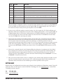
GSC3000 / LYNX 4
QUICK START GUIDE
INTRODUCTION
The GSC3000 streamlines your remote facilities management by providing a single control interface for your
equipment while offering flexibility in control points and communication links. This Quick Start guide will take
you through each step of installing and connecting to your GSC3000 system. The Installation and Operations
manual contains a system overview and diagrams of all included equipment, as well as details on the system’s
advanced features.
ADDING A NEW I/O UNIT TO AN EXISTING SITE
If you are connecting a new I/O unit to an existing GSC3000 installation, most of your software and hardware
setup is already complete. To connect a new unit to an existing site:
1. Change the unit number on the new I/O unit to one that is not already used at your site. See step 7 in
section A, below.
2. Link the new I/O unit to an existing I/O unit using the included RJ-45 G-Bus jumper cable, and set up the
Unit Configuration for your new unit. See steps 8-10 in section A, below.
3. Connect your input and command channels. See steps 3-4 in section B, below.
INSTALLING A NEW GSC3000 SYSTEM
A. Software Setup
Lynx requires Microsoft Windows® 2000 Professional, or Windows XP (Home or Professional). You can verify
additional system requirements in the first chapter of the Installation and Operations manual.
1. If you have been using a previous version of Lynx software, archive your existing unit configurations before
installing the new software. Refer to the Lynx 3.5 manual for instructions. If you have been using
GSC3000 1.9 software, you will have to reenter your configuration settings when you set up Lynx 4.
2. Every time you install Lynx 4, you will need to supply the CD key provided by Burk Technology. If your
copy of Lynx is on CD-ROM, your product is already registered and the CD Key is affixed to the CD
sleeve. If you downloaded your copy of Lynx, you need to register the product by following the
registration link from the Downloads section of the Burk Technology web site. When you register your
product, the CD key will be sent to you via email.
3. Insert the Lynx CD in your CD-ROM drive, and when the install window appears, click the Install option.
Follow the on-screen instructions to complete Lynx installation. If you downloaded your copy of Lynx,
double-click the Setup file.
4. Double-click the Lynx icon on your desktop to run the application. When the login screen appears, the
default user name is Administrator. Leave the password blank. Click Login to begin.
GSC3000 / LYNX 4 QUICK START GUIDE (REV A)
1
5. IMPORTANT! Lynx 4 introduces new I/O and Voice Interface firmware. If you are upgrading from a
previous version of software, you will need to upload new firmware to your units before using Lynx 4. Refer
to Appendix A in the Installation and Operations manual. When you upload firmware, you have the option
to assign a unit number to your I/O units. If you are setting up a factory new system, assign a unique unit
number to each I/O unit (0-15), and be sure one unit is identified as Unit 0. When you set unit numbers
this way, skip step 7, below.
6. Before you can connect to any units, you must create a new site in Lynx. Click the New Site
icon in the
toolbar and follow the on-screen instructions. What’s This Help is available, and each step of the Site
Wizard is described in the onboard Help File and in the Installation and Operations manual.
7.
After you create your site, set the unit number for each of your I/O units, if you did not set the unit
number in step 5, above. Note: if you are using Lynx 4 with an existing GSC3000 setup, you do not have
to change unit numbers. To set the unit number, use the supplied null modem cable to connect your PC to
COM1 on the I/O unit. From the File menu, select Assign Unit Number. Specify the PC COM port you are
using, enter the site password (the default is PASSWORD), and use the drop-down menu to specify a unit
number. Every unit needs to have a unique number, and one unit needs to be identified as unit 0. The unit
number for a Voice Interface unit is always 16, and cannot be changed.
8. Now that every I/O has a distinct unit number, you can network all your units so that Lynx will recognize
them at your site. Use the included RJ-45 jumper cables to link a G-Bus port on the rear panel of one I/O
to a G-Bus port on the next I/O. It makes no difference whether you link G-Bus 1 to G-Bus 2 or viceversa. If you are using a Voice Interface, connect it to the G-Bus network in the same way as an I/O unit.
9. After linking each unit, connect a G-Bus terminator to the unused G-Bus port on the first unit and to the
unused G-Bus port on the last unit.
10. While you are still direct connected to your site, click Connect
to connect to your site. The Site List
expands to show icons for all units at your site. Click on a unit icon and select Unit Configuration
from
the toolbar. Fill in configuration settings for each tab in the configuration menu and click Save to Unit
when you are finished. Complete the configuration menu for all units at your site. If you have archived
configurations, you can open them inside the configuration menu by clicking Open .
B. Hardware Setup
After you have set up your site in Lynx and entered configuration parameters for each unit, you are ready to go to
the remote site and make the hardware connections to your system.
1. If you are using a dial-up modem to connect to your site, first install the PC modem according to
manufacturer’s instructions. If you are using the recommended U.S. Robotics 56K V.92 external dial-up
modem with the GSC3000, configure the DIP switch settings as shown on the following page.
2
CUSTOMER SUPPORT: 978-486-3711 • [email protected] • www.burk.com
DIP
SWITCH POSTION
FUNCTION
1
UP
Data Terminal Ready
2
UP
Verbal Result Codes
3
DOWN
Enables Result Code Display
4
DOWN
No echo, offline commands
5
UP (I/O unit)
DOWN (Voice Interface)
Enables auto answer. The modem will answer the incoming call for the I/O unit.
Disables auto answer. The voice interface will automatically answer the call.
6
UP
Carrier detect normal
7
UP
Load NVRAM defaults
8
DOWN
Smart mode
After the modem is configured, connect it to any I/O or Voice Interface unit at your site, using COM2 for
an I/O or COM1 for a Voice Interface. Use the supplied DB9-25 straight-through cable. Then connect
the modem to the RJ-11 wall jack and cycle the power on the GSC3000.
2. If you are using a full-time modem to connect to your site, refer to pages 44-45 of the Installation and
Operations manual for configuration instructions. After configuring the modems, use the supplied DB9-25
straight-through cables to connect the studio modem to an available COM port on your PC and COM1
on an I/O unit. Do not connect a full-time modem to a Voice Interface or to COM2 on the I/O. Power
cycle the GSC3000 after connecting the modem.
3. Connect the input channels to the Wiring Interface unit by wiring your site equipment to the included
two-terminal push-on blocks and connecting the blocks to the rear panel of the wiring interface. For an
I/O-16 (sixteen channels of metering, status and command), use two Wiring Interfaces, with one
designated for metering and the other for status. For an I/O 8, connect your metering and status channels
to the same wiring interface. When you are done, use the supplied DB-37 connector to link the Wiring
Interface to the METERING or STATUS port on the I/O 16, or the METERING/STATUS port on an I/O 8
unit.
4. Connect the command channels to the Command Relay by wiring your site equipment to the included
three-terminal push-on blocks and connecting the blocks to the rear panel of the Command Relay. The
Command Relay supports eight command channels; use two Command Relays for sixteen channels of
command. Use the supplied DB-37 connector to link the Command Relay to the COMMAND 1-8 or the
COMMAND 9-16 port on the I/O unit.
5. After your I/O and Voice Interface units are configured, your communication equipment installed, and the
input and command channels connected, your site is ready for operation. Refer to the Installation and
Operations manual for details on the monitoring and control capabilities of the system.
GETTING HELP
Detailed setup and configuration instructions may be found in the Installation and Operations manual. If you still
need help, please visit the support section of the Burk Technology web site at www.burk.com, or contact Burk
Technology customer support.
Tel:
978-486-3711
Fax:
978-486-0081
Email: [email protected]
GSC3000 / LYNX 4 QUICK START GUIDE
3