1
CLEAR-COM ENCORE
SYSTEM INSTALLATION
INSTRUCTION MANUAL
Encore System Installation Instruction Manual
© 2009 Vitec Group Communications Ltd. All Rights Reserved.
Part Number 810229Z Rev. 4
Vitec Group Communications LLC
850 Marina Village Parkway
Alameda, CA 94501
U.S.A
Vitec Group Communications Ltd
7400 Beach Drive
IQ Cambridge
Cambridgeshire
United Kingdom
CB25 9TP
The Vitec Group plc
Beijing Representative Office
Room 706, Tower B
Derun Building, YongAn Dongli A No.3
Jianwai Ave., Chaoyang District
Beijing, P.R.China 100022
® Clear-Com, CellCom/FreeSpeak and the Clear-Com Communications Systems logo are registered trademarks of
The Vitec Group plc.
Website: www.clearcom.com
CONTENTS
Introduction . . . . . . . . . . . . . . . . . . . . . . . . . . . . . . . . . . . . . . . . . . . . 1-1
The Clear-Com Concept. . . . . . . . . . . . . . . . . . . . . . . . . . . . . . . . . . 1-1
Power Distribution and Short Circuit Protection . . . . . . . . . . . . . . . . 1-2
Installing an Intercom System. . . . . . . . . . . . . . . . . . . . . . . . . . . . . . 1-3
Single-Channel System. . . . . . . . . . . . . . . . . . . . . . . . . . . . . . . . . 1-4
Multi-Channel System . . . . . . . . . . . . . . . . . . . . . . . . . . . . . . . . . . 1-5
Crosstalk Considerations in a Multi-Channel System . . . . . . . . . . 1-6
Intercom Cable Considerations . . . . . . . . . . . . . . . . . . . . . . . . . . . 1-7
Installing the StatioNS. . . . . . . . . . . . . . . . . . . . . . . . . . . . . . . . . . . . 1-8
Connections . . . . . . . . . . . . . . . . . . . . . . . . . . . . . . . . . . . . . . . . . 1-8
Configuring Clear-Com Products to Work Together . . . . . . . . . . 1-12
TW-40/TW-47 Two-Way Radio Interface. . . . . . . . . . . . . . . . . 1-12
KB-112/KB-212/KB-701 Speaker Station . . . . . . . . . . . . . . . . 1-13
RM-220/RM-702 Remote Station . . . . . . . . . . . . . . . . . . . . . . 1-13
Typical Applications . . . . . . . . . . . . . . . . . . . . . . . . . . . . . . . . . . . . 1-15
Cable or School Television Studio. . . . . . . . . . . . . . . . . . . . . . . . 1-15
TheatrE 1 . . . . . . . . . . . . . . . . . . . . . . . . . . . . . . . . . . . . . . . . . . 1-17
Theatre 2. . . . . . . . . . . . . . . . . . . . . . . . . . . . . . . . . . . . . . . . . . . 1-19
ENG/EFP Truck. . . . . . . . . . . . . . . . . . . . . . . . . . . . . . . . . . . . . . 1-21
System Checkout . . . . . . . . . . . . . . . . . . . . . . . . . . . . . . . . . . . . . . 1-23
Check Termination . . . . . . . . . . . . . . . . . . . . . . . . . . . . . . . . . . . 1-23
Check Intercom Cable Resistance . . . . . . . . . . . . . . . . . . . . . . . 1-23
Final Tests . . . . . . . . . . . . . . . . . . . . . . . . . . . . . . . . . . . . . . . . . . 1-24
After you turn the power ON: . . . . . . . . . . . . . . . . . . . . . . . . . . 1-24
Troubleshooting . . . . . . . . . . . . . . . . . . . . . . . . . . . . . . . . . . . . . . . 1-25
Glossary . . . . . . . . . . . . . . . . . . . . . . . . . . . . . . . . . . . . . . . . . . . . . 1-27
CONFIGURATION OPTIONS . . . . . . . . . . . . . . . . . 2-1
Party Line Products . . . . . . . . . . . . . . . . . . . . . . . . . . . . . . . . . . . . . 2-1
PROGRAM AUDIO TO ANNOUNCE OUTPUT OPTION. . . . . . . . . 2-3
Theatre Application . . . . . . . . . . . . . . . . . . . . . . . . . . . . . . . . . . . . 2-3
Setting the Option . . . . . . . . . . . . . . . . . . . . . . . . . . . . . . . . . . . . . 2-5
System Setup . . . . . . . . . . . . . . . . . . . . . . . . . . . . . . . . . . . . . . . . 2-6
Clear-Com Communication Systems
Encore System Installation Instruction Manual
i
ADDENDUM: POWER CORDS. . . . . . . . . . . . . . . . 3-1
LIMITED WARRANTY . . . . . . . . . . . . . . . . . . . . . . . W-I
TECHNICAL SUPPORT & REPAIR POLICY. . . . . W-V
TECHNICAL SUPPORT POLICY . . . . . . . . . . . . . . . . . . . . . . . . . . W-v
RETURN MATERIAL AUTHORIZATION POLICY . . . . . . . . . . . . . W-vi
REPAIR POLICY . . . . . . . . . . . . . . . . . . . . . . . . . . . . . . . . . . . . . W-viii
ii
Clear-Com Communication Systems
Encore System Installation Instruction Manual
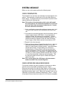
IMPORTANT SAFETY
INSTRUCTIONS
Please read and follow
these instructions
before operating this
product.
1. Read these instructions.
2. Keep these instructions.
3. Heed all warnings.
4. Follow all instructions.
5. Do not use this apparatus near water.
6. Clean only with dry cloth.
7. Do not block any ventilation openings. Install in accordance with the
manufacturer’s instructions.
8. Do not install near any heat sources such as radiators, heat
registers, stoves, or other apparatus (including amplifiers) that
produces heat.
9. Do not defeat the safety purpose of the polarized or grounding-type
plug. A polarized plug has two blades, with one blade wider than
the other. A grounding-type plug has two blades and a third
grounding prong. The wide blade or the third prong are provided for
your safety. If the provided plug does not fit into your outlet, consult
an electrician for replacement of the obsolete outlet.
10. Protect the power cord from being walked on or pinched
particularly at plugs, convenience receptacles, and the point where
they exit from the apparatus.
11. Only use attachments/accessories specified by the manufacturer.
12. Use only with the cart, stand, tripod, bracket, or table specified by
the manufacturer, or sold with the apparatus. When a cart is used,
use caution when moving the cart/apparatus combination to avoid
injury from tip-over.
13. Unplug this apparatus during lightning storms or when unused for
long periods of time.
14. Refer all servicing to qualified service personnel. Servicing is
required when the apparatus has been damaged in any way, such
as power-supply cord or plug is damaged, liquid has been spilled
or objects have fallen into the apparatus, the apparatus has been
exposed to rain or moisture, does not operate normally, or has
been dropped.
15. WARNING: To reduce the risk of fire or electric shock, do not
expose this product to rain or moisture.
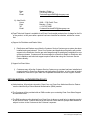
Please familiarize yourself with the safety symbols in Figure 1. When
you see these symbols on this product, they warn you of the potential
danger of electric shock if the speaker station is used improperly. They
also refer you to important operating and maintenance instructions in
the manual.
Clear-Com Communication Systems
Encore System Installation Instruction Manual
i
CAUTION
RISK OF ELECTRIC SHOCK
DO NOT OPEN
This symbol alerts you to the presence of uninsulated dangerous
voltage within the product's enclosure that might be of sufficient
magnitude to constitute a risk of electric shock. Do not open
the product's case.
This symbol informs you that important operating and maintenance instructions are included in the literature accompanying
this product.
Figure 1: Safety Symbols
EMC AND SAFETY
The Clear-Com Encore product line meets all relevant CE, FCC, UL,
and CSA specifications set out below:
EN55103-1 Electromagnetic compatibility. Product family standard for
audio, video, audio-visual, and entertainment lighting control apparatus
for professional use. Part 1: Emissions.
EN55103-2 Electromagnetic compatibility. Product family standard for
audio, video, audio-visual, and entertainment lighting control apparatus
for professional use. Part 2: Immunity.
UL 60065-7, CAN/CSA-C22.2 No.60065-3, IEC 60065-7 Safety
requirements.
And thereby compliance with the requirement of Electromagnetic
Compatibility Directive 2004/108/EC and Low Voltage Directive
2006/95/EC
This device complies with Part 15 of the FCC Rules. Operation is
subject to the following two conditions: (1) this device may not cause
harmful interference, and (2) this device must accept any interference
received, including interference that may cause undesired operation.
ii
Clear-Com Communication Systems
Encore System Installation Instruction Manual
1
INTRODUCTION
Congratulations on choosing Clear-Com products. Clear-Com was
established in 1968 and remains the market leader in providing
intercom for entertainment, educational, broadcast and industrial
applications. The ruggedness and high build-quality of Clear-Com
products is the industry standard. In fact, many of our original
beltpacks and Main Stations are still in daily use around the world.
We recommend that you read through this manual completely to better
understand how to install your intercom system. Please pay particular
attention to the section on system wiring, as improper wiring detracts
from the performance of the system or causes system failure. If you
encounter a situation or have a question that this manual does not
address, contact your dealer or call Clear-Com direct at the factory.
Our applications support and service people are standing by to assist
you. Thank you for selecting Clear-Com for your communications
needs.
THE CLEAR-COM CONCEPT
Clear-Com is a closed-circuit intercom system that consistently
provides high-clarity communication in both high-noise and low-noise
environments. A basic system consists of a single- or multi-channel
Power Supply or Main Station connected to various single- or
multi-channel Remote Stations, such as beltpacks and loudspeaker
stations.
Clear-Com is a distributed amplifier system; each Main or Remote
Station houses its own microphone preamplifier, headset or speaker
power amplifier, and signaling circuitry. Stations bridge the intercom
line at a very high impedance and place a minimum load on the line.
The audio level always remains constant, and does not fluctuate as
stations leave and join the system. Low-impedance mic input lines
and specially designed circuitry make Clear-Com channels virtually
immune to RFI and dimmer noise.
Clear-Com stations are interconnected with two-conductor, shielded
microphone cable (or individually shielded multi-pair cable as
required). Portable stations are connected with 2 conductor cables
with 3-pin XLR connectors. One wire, connected to pin 2, carries the
DC power from a Main Station or Power Supply to all Remote Stations.
The other wire, connected to pin 3, carries the 2-way (duplex) audio
information. The shield, connected to pin 1, acts as a common ground.
One termination per channel is needed throughout the intercom
network, and is usually located in the Main Station or Power Supply.
Clear-Com Main Stations, Power Supplies and certain Remote
Stations each have an auxiliary program input with its own volume
control, which allows an external audio source to be fed to the intercom
system.
Clear-Com Communication Systems
Encore System Installation Instruction Manual
1-1
Visual Signal Circuitry (Call Lights), a standard feature on all Main and
Remote Stations, allows the user to attract the attention of operators
who have removed their headsets. Certain stations also have an
audible Tone Alert feature which can be useful for this purpose.
Clear-Com manufactures a wide variety of both portable and
fixed-installation units. All are compatible with each other. Clear-Com
intercom systems can also interface with other communication
systems and devices.
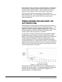
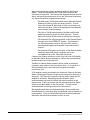
POWER DISTRIBUTION AND SHORT CIRCUIT PROTECTION
A Main Station or Power Supply is the heart of an intercom system. It
has special features which are not found in traditional designs. It must
supply low-noise DC current to multiple intercom lines. It must
continue to operate in adverse conditions such as low AC line voltage,
momentary shorts on the DC power lines to the stations, and
excessive peak loads during power-on conditions.
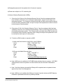
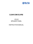
Use the chart on this page to determine how many Speaker Stations
and Beltpacks can be powered in varying combinations by a Main
Station or Power Supply. Additional power supplies can be connected
for additional power capability if required by the application. The
current requirements of Clear-Com Remote Stations and Beltpacks
vary with model and use. A station which is simply '"on" and not being
used may draw only a small amount of current. Contact your dealer or
Clear-Com if you require further assistance in determining the overall
current requirements of your system.
Figure 1-1: Power Supply Loading
For example, the MS-702 provides DC power to operate Clear-Com
beltpacks and remote stations. The power is distributed between the
two channels and will support up to 40 RS-601 beltpacks or 10
speaker stations or 12 headset stations.
1-2
Clear-Com Communication Systems
Encore System Installation Instruction Manual
Clear-Com’s fail-safe design automatically shuts down the power to a
channel when a short circuit or electronic overload is sensed on that
channel. The other channel will continue to operate normally. Once the
fault condition is removed, the MS-702’s fail-safe circuit will restore
power, even under full load conditions. LED indicators signal a short or
overload on either channel.
The DC power output details are:
• 1.2A continuous output
• 2A peak output (not exceeding the 1.2A rating for more than 2
seconds per 1 minute period)
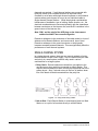
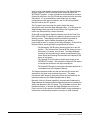
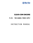
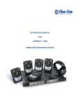
The station internal power supply senses the difference between
short-term and long-term shorts and overload conditions. After the first
few times a short or overload occurs, the power supply will try to
restore power after only 0.5 seconds. If the short or overload persists
or occurs repeatedly, the power supply will take progressively longer
(to a maximum of 20 seconds) to try to restore power. This protects the
power supply from damage due to overheating. Once the short is
removed, the channel will recover, even under a full load condition.
The automatic power restore times are shown in the following chart:
20
20
14
15
Numberof
secondsto
restore
10
7
5
4
2
0.5
0
0 1 2 3 4 5 6 7 8 9 10 11 12 13 14 15 16 17 18 19 20
Numberofrecentshortsoroverloads
Figure 1-2: Automatic Power Restore Times
Shorts are generally caused by miswiring or damaged cables.
Overloads are generally caused by connecting too many beltpacks
and stations to a channel.
INSTALLING AN INTERCOM SYSTEM
When considering how to install and wire an intercom system, several
factors must be taken into account. These include the number of
stations, the length of the cable runs and whether single or multiple
Clear-Com Communication Systems
Encore System Installation Instruction Manual
1-3
channels are required. If multi-channel stations are connected with
multi-pair cables, then crosstalk becomes an important issue.
Crosstalk is not a factor with single-channel systems or multi-channel
systems where each channel is run on its own individual cable to
single-channel Remote Stations. While the physical considerations
include ease of installation, type of cabling, station location, etc., the
electrical considerations are concerned primarily with the capacitance
between conductors on the intercom line, and the DC resistance in the
ground return of the intercom line.
Note: PIN 1 and the shell of the XLR plug on the interconnect
cables should NOT be connected together.
Excessive resistance in the conductors of the cable results in a loss of
sidetone null at Remote Stations, and some overall loss of level.
Excessive resistance in the ground conductor or shield greatly
increases crosstalk between channels. This can significantly affect the
performance of multi-channel systems.
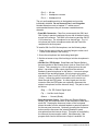
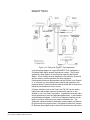
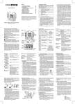
SINGLE-CHANNEL SYSTEM
In a single-channel system, there are two general methods of wiring
Remote Stations to the Power Supply. Any one method may be used
exclusively in a small system, and both may used in various
combinations for a larger system.
1. Daisy Chain: Remote stations are wired from one station to the
next and so on along each line connected to a Main Station. This
requires the least amount of cable, but may be impractical due to the
system layout. Also, if a break occurs in the line, all stations down
line of the break will be disconnected from the party line.
Figure 1-3: Party Line Daisy Chain
2. Hub or Star: Each Remote Station is wired directly back to a Main
Station or to a split of a line wired directly to a Main Station.
1-4
Clear-Com Communication Systems
Encore System Installation Instruction Manual
Figure 1-4: Party Line Hub Configuration
MULTI-CHANNEL SYSTEM
In a multi-channel system where each channel is run on its own cable
and connected only to single channel Remote Stations as in the
following diagram, there are no crosstalk issues because the channels
do not share a common ground. Consult the table in the next section
for cable recommendations.
Figure 1-5: Multi-Channel Party Line
It is also important to centrally locate the multi-channel Main Station or
Power Supply containing the termination. Crosstalk does not exist at
the termination point, but can increase in proportion to the length of the
wiring to multi-channel stations. If the termination is centrally located
and the wiring length guidelines in the following section are adhered to,
then crosstalk will be at a minimum.
Clear-Com Communication Systems
Encore System Installation Instruction Manual
1-5
CROSSTALK CONSIDERATIONS IN A MULTI-CHANNEL SYSTEM
In a multi-channel system where multiple channels are run from a Main
Station to a Remote Station as in the following diagram, crosstalk can
be an issue. This is because the channels will share a common
ground at both ends of the cable run.
Figure 1-6: Party Line Multi-Channel Configuration
When multiple channels are fed to Remote Stations, the amount of
crosstalk between channels is proportional to the DC resistance of the
ground return path back to the channel terminations. To minimize this
crosstalk between channels when running more than one channel in a
multi-pair cable, keep the DC resistance of the ground return as low as
possible. Ideally, this should be less than 2 Ohms. This can be
achieved as follows:
• Keep cable runs under 500 feet. If a longer cable run is
unavoidable and approaches 1000 feet or more, make sure
the appropriate lone line option switches or jumpers are set in
the stations. Refer to the individual station manuals for
further information.
• Use a cable whose common shield has a low DC resistance.
• Connect unused cable wires of a multi-pair cable to the Pin 1
shield.
Note: All multi-pair cables must have individually shielded pairs.
Clear-Com recommends the Belden 1800 Series of multi-pair cables.
They offer a common shield with a low DC resistance in addition to
individual shields on each pair.
1-6
Clear-Com Communication Systems
Encore System Installation Instruction Manual
The performance of a Clear-Com system depends upon the use of
Clear-Com or Clear-Com approved compatible headsets. Use of
headsets other than these can induce crosstalk into a multi-channel
system through the headset cable. Clear-Com also recommends
against the use of headset extension cables or headset "Y" cables, as
they will increase crosstalk into a multi-channel system.
INTERCOM CABLE CONSIDERATIONS
The Clear-Com intercom line is intended to run on one shielded cable
pair per intercom channel. One conductor carries audio, and the other
conductor carries the DC power for Remote Stations. The shield
serves as the ground return for the audio and power conductors.
When choosing interconnect cable, keep the following considerations
in mind:
• Keep cable runs under 500 feet. The DC resistance of the
ground or common conductor affects crosstalk. For
permanent installation runs longer than 500 feet, do not use
wire smaller than 20 gauge. The capacitance of the
interconnect cable affects system frequency response and
sidetone stability. Total capacitance should not be greater
than 0.25 uF.
• Ground Isolation: The Pin 1 ground connection of each
XLR connector must be isolated from the chassis. Pin 1
should not be connected to the shell of the XLR connector.
• Multi-pair Cable: Individually shielded multi-pair cable is
acceptable for use in multi-channel systems. For crosstalk
considerations the shields must be tied together on both ends
of the cable to produce the lowest possible DC resistance
path for the ground return.
• Suggested Cable Types: The following chart lists the
specifications of various BELDEN cables:
Clear-Com Communication Systems
Encore System Installation Instruction Manual
1-7
BELDEN SHIELDED CABLES
Trade
#
# of
Pairs
AWG &
Stranding
Nom. O.D.
(inch)
Nom. Cap.
(pF/ft)
8412.000
1.000
20 (26x34)
0.268
8762.000
1.000
20 (7x28)
8760.000
1.000
1814A
Shield
Nom. D.C.R.
(Ohms)
Max.* Cable
Run (ft)
Recommended
Application
30.000
5000.000
Portable
0.196
27.000
5000.000
Permanent
(short)
18 (16x30)
0.222
24.000
5000.000
Permanent
(long)
2.000
22 (7x30)
0.319
31.000
3.9 Ω/M'
1500.000
Permanent
1815A
4.000
22 (7x30)
0.384
31.000
3.9 Ω/M'
1500.000
Permanent
1817A
8.000
22 (7x30)
0.503
31.000
3.6 Ω/M'
1500.000
Permanent
1818A
12.000
22 (7x30)
0.889
31.000
3.4 Ω/M'
1500.000
Permanent
Table 1-1: Belden Shielded Cables
Note: For better than 50 dB channel crosstalk
• Portable Installation Cable: Practical cable for portable
system interconnections is flexible, two-conductor, shielded
microphone cable. We suggest using BELDEN #8413 (24
Gauge). For runs longer than 500 feet use a 20 gauge cable
or larger (BELDEN #8412).
• Permanent Installation Cable: Vinyl-jacketed shielded pair
is the cable of choice for permanent installations. Placing the
cable in conduit is recommended but not necessary.
INSTALLING THE STATIONS
First, choose the location for the Main Station or Power Supply. These
units require access to AC power. They should be located away from
other equipment that generates excessive amounts of heat. Also,
choose locations for each Remote Station and Speaker Station.
Choose general locations and areas of use for the beltpacks.
Determine the locations for other Clear-Com equipment which will
connect to the intercom lines. The choice of location will depend upon
and often define the wiring scheme. It is very helpful to create a
drawing showing where each component will be located as well as
where the wiring will run.
CONNECTIONS
The following sections describe the connections provided on the
intercom stations:
• Intercom Line Connection: The rear panel of Main Stations,
Power Supplies, Remote Stations, and other stations contain
between one and three 3-pin male XLR connectors for each
1-8
Clear-Com Communication Systems
Encore System Installation Instruction Manual
intercom line. These connectors are wired in parallel. Any
single-channel station or channel of a multi-channel station
connected on a line plugged into Channel A of the a Main Station
will be "party-lined" with all the other stations on that channel. In
a multi-channel system, the goal is to assign specific people to
the correct group, i.e. the other people they need to be in contact
with the most. This is particularly important when the party line
users are on a single-channel beltpack or station; less so if they
are on multi-channel stations. The pinout of the intercom
connectors is as follows:
• Pin 1 --- Ground (Shield)
• Pin 2 --- Power
• Pin 3 --- Audio
• Line Termination: The fundamental concept of Clear-Com
Party-Line intercom is that all channels are terminated in one
location, preferably at a Main Station or Power Supply.
Note: All intercom lines must be terminated. Care must be taken
not to '"double-terminate" a line. All unused intercom lines
must also be terminated.
Switching of the channel terminations ON and OFF is done with
switches or jumpers on the Main Station. In most systems, the
terminations should be in the ON position (default setting).
Clear-Com Power Supplies also provide switch-selectable
termination networks on all intercom lines. Refer to the User
manual for the specific Main Station or Power Supply for the exact
location. It is up to the user to ensure that the terminations are set
correctly. An unterminated line will cause excessive levels, possible
oscillation of line drivers, and squealing in the headsets. An
intercom line with double or multiple terminations will cause low
levels and the inability to null the headsets.
The termination switches on a Main Station should be set to the OFF
position only if the channel is terminated by another Main Station or
Power Supply in the system. If there are no other Main Stations
or Power Supplies terminating the line, the termination switch
on each channel of the Main Station should be switched to ON.
• Headset Connector: The headset connector is located on the
front panel of all stations. Clear-Com headsets are
recommended, but others can be used if they meet the following
requirements:
• Mic Type --- Dynamic; 150 to 250 ohms impedance; -55 dB
output level
• Headphone --- Dynamic; 50 to 2000 ohms impedance
The wiring of the headset is to be as follows:
• Pin 1 --- Mic common
Clear-Com Communication Systems
Encore System Installation Instruction Manual
1-9
• Pin 2 --- Mic hot
• Pin 3 --- Headphone common
• Pin 4 --- Headphone hot
The mic and headphone wiring in the headset cord must be
individually shielded. Do not connect Pins 1 and 3 together.
Headset extension cords or headset "Y" cables are not
recommended because they will increase crosstalk between
channels.
• Panel Mic Connector: Clear-Com recommends the GM-9 and
GM-18 plug-in panel microphones for use with all stations having
a panel mic connector. The GM-9 is 9 inches long and the GM-18
is 18 inches long. The microphone is an electret type. The 1/4
inch phone jack on the microphone mates with the Panel Mic
receptacle on the front panel.
To install a GM-9 or GM-18 microphone, use the following steps:
1. Check the set screw in the mic mounting flange to make sure it
is clear of the threads in the bushing.
2. Screw the microphone into the bushing hand tight.
3. Set the set screw on top of the bushing to lock the microphone in
place.
• Hot Mic Out / IFB System: Some Main and Remote Stations
have an interface to the External Line In jack on Clear-Com's IFB
System. This connection is a 1/4 inch phone jack on the rear
panel. It provides a 0 dBu output signal from the selected
headset or panel microphone on the station. It connects using a
standard 2-wire and shield stereo 1/4 inch plug-to-plug cable
such as the Clear-Com P/N 73016501 (18 inch) or P/N 73016502
(5 foot). It allows the station's microphone to be used to cue
talent through the IFB System. A control signal sent into this
connector from the IFB System can optionally disconnect the
station's microphone from the intercom line(s). The jack is wired
as follows:
• Ring --- Ext. IFB Control Signal Input
• Tip --- Hot Mic Audio Output
• Sleeve --- Ground (Shield)
• Stage Announce Output: Some Main and Remote Stations
have a 3-pin XLR male connector on the rear panel to feed into a
studio PA. Pressing the Announce button on the front panel
places the audio from the selected headset or panel microphone
on the rear panel connector. Optionally, pressing the Announce
button can also disconnect the selected headset or panel
microphone from the intercom line(s). This option is controlled by
the Interrupt Announce option switch. Simultaneously, if the
program audio feed to the Announce Output is enabled, it is
1-10
Clear-Com Communication Systems
Encore System Installation Instruction Manual
interrupted by the announcement. Program audio feed to the
Announce Output is selected by setting a jumper on the Main
board to the ON position. The pinout of the Announce Out
connector is as follows:
• Pin 1 --- Ground (Shield)
• Pin 2 --- - Signal
• Pin 3 --- + Signal
The audio output is balanced and transformer isolated. It has a 600
ohm impedance and a nominal output level of 0 dBu. A shielded
twisted pair cable should be used in the cable wired to this
connector.
• Relay Out: On Main and Remote Stations with an Announce
button, a dry set of relay contacts is provided through a 1/4 inch
jack or screw terminals on the rear panel. These contacts can
activate an external device such as a PA amplifier to another
room. The contacts are rated for 2.0 Amps at 24 VDC. If screw
terminals are provided on the Main Station, their connections are
labeled N/C, C and N/O. The 1/4 inch jack is wired as follows:
• Ring --- Normally Closed Contact --- N/C
• Tip --- Common Contact --- C
• Sleeve --- Normally Open Contact --- N/O
• Program Input: A 3-pin XLR female connector on most Main
Stations and Power Supplies provides the program input to the
intercom system. The Program Input accepts a balanced or
unbalanced line-level audio signal from -20 dBu to +10 dBu.
There is an option to feed program audio to the Announce
Output. This is selected by setting a jumper on the Main board to
the ON position. When this option is selected, a 0 dBu signal on
the Program Input will produce a 0dBu signal on the Announce
Output.
The pinout of the Program Input connector is as follows:
• Pin 1 --- Ground (Shield)
• Pin 2 --- + Signal
• Pin 3 --- - Signal
• External Speaker: Some Main Stations provide an 8 ohm
external speaker output through a 1/4 inch jack.
• Auxiliary Connector: Some Main Stations provide a DB-15 type
Auxiliary connector on the rear panel. This allows connection to a
variety of devices, depending upon the capabilities and features
of that particular Main Station. Refer to the Main Station User
Manual for further details on the connections provided.
Clear-Com Communication Systems
Encore System Installation Instruction Manual
1-11
• AC Power Connection: An IEC type 320 connector is provided
on most Main Stations and Power Supplies to interface to the
appropriate AC power cord to be used. Refer to the chart on the
inside back cover of this manual. Main Stations and Power
Supplies can either be switched between 115 or 230 VAC
operation or will automatically adjust to voltages from 100 to 240
VAC at 50 or 60 Hz. Consult the User Manual for information on
the particular unit.
CONFIGURING CLEAR-COM PRODUCTS TO WORK
TOGETHER
Clear-Com Intercom Systems are designed to integrate with many
other Clear-Com products. The following sections describe some
frequently used configurations. Most of these configurations involve
the use of Clear-Com's versatile Call signal. This signal travels silently
through the intercom wiring and is often used to get the attention of
operators who have removed their headsets. However, as the
following descriptions show, it can also be used to control a variety of
functions.
TW-40/TW-47 Two-Way Radio Interface
The TW-40 is an earlier version of the TW-47 product but both product have
the same functionality.
It is often important to link walkie-talkies into an intercom system to
extend communication to remote persons. The TW-47 Two-Way
Radio Interface connects between an intercom line and a variety of
walkie-talkies, using one walkie-talkie as a base station. Refer to the
TW-47 Instruction Manual for details describing the connection of the
TW-47. To interface with the TW-47, the option switches of the Main or
Remote Station must be set as follows:
• Enable the Momentary Talk option switch or jumper on the
appropriate channel of the Main or Remote Station. Refer to
the User Manual for the Main or Remote Station to locate this
switch or jumper. This will cause the Talk button to have a
momentary only action and not latch.
• Enable the Call on Talk option switch or jumper on the
appropriate channel of the Main or Remote Station. Again,
refer to the User Manual for the Main to locate this switch or
jumper. This will cause the Call signal to be activated
whenever the Talk button is held down.
When the Talk button is depressed, the Call signal will be activated,
causing the transmitter connected to the TW-47 to be keyed. Audio on
the intercom line will then be transmitted over the two-way radio.
When the Talk button is released, the Call signal will disappear and
audio from the receiver of the two-way radio will appear on the
intercom line, allowing a reply.
1-12
Clear-Com Communication Systems
Encore System Installation Instruction Manual
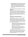
KB-112/KB-212/KB-701 Speaker Station
KB-112, KB-212 and KB-701 stations are all sucessive models of
single channel speaker stations with similar functionality. In the
following description the current model KB-701 is cited but the
functionality is similar or identical on the earlier stations.
The KB-701 Speaker Station provides intercom communication
capability in places where wearing a headset is not feasible. It can be
optioned for several remote control functions. Refer to the appropriate
Instruction Manual for details on setting the option switches.
A Main or Remote Station can control the microphone on a KB-701 set
to Remote Listen operating mode, allowing the KB-701 operator to talk
"hands free." When the option switches of the KB-701 are set to this
mode, depressing the Call button on the Main or Remote Station will
turn on the microphone of the KB-701. Care must be taken in the
design of the intercom system to make sure that the call signal will not
be needed for other functions on the same channel. For example, it
would not be possible to interface both the TW-47 and a KB-701 in
Remote Listen mode on the same intercom channel. In this case,
separate intercom channels should be used for each interface.
The KB-701 also has Remote Page and Remote Listen-Page modes.
In these modes, the speaker of the KB-701 can be turned on by a Call
signal from the Main Station. The flexibility of Clear-Com Main and
Remote Stations allows the following variations on these modes:
• A Main or Remote Station can be used to talk to other
intercom stations, and enable the KB-701 speaker only when
necessary. To talk to all intercom stations except the KB-701,
press the Main or Remote Station Talk button. To talk to the
KB-701 as well, press both the Call and Talk buttons.
• A Main or Remote Station can enable the KB-701 speaker
whenever the operator is talking to other intercom stations.
Set the Call on Talk option switch or jumper for the channel
the KB-701 is on. This will cause the Call signal to be
activated whenever the Talk button is held down. This will
have the effect of turning on the KB-701 speaker whenever
the Talk button is pressed. If it is preferable to prevent the
Talk button from latching, set the Momentary Talk option
switch or jumper for that channel to the ON position. This will
cause the Talk button to have a momentary only action and
not latch.
RM-220/RM-702 Remote Station
RM-220 and RM-702 stations are sucessive models of two channel
remote stations with similar functionality. In the following description
the current model RM-702 is cited but the functionality is similar or
identical on the earlier station.
Clear-Com Communication Systems
Encore System Installation Instruction Manual
1-13
A Main Station, such as the MS-232 or MS-702can be configured to
provide program audio on a channel but allow this audio to be
interrupted whenever the Talk button for that channel is pressed. If a
Remote Station, such as the RM-220 or RM-702 is used along with the
Main Station in this configuration, it can be important to have the
program audio interrupted by the operator of either station. To do this,
the Main or Remote Stations must be set up as follows:
• Enable the Momentary Talk option switch or jumper on the
appropriate channel of the Main and Remote Stations. Refer
to the User Manual for to locate this switch or jumper. This
will cause the Talk button to have a momentary only action
and not latch.
• Enable the Call on Talk option switch or jumper on the
appropriate channel of the Main and Remote Stations. Again,
refer to the User Manual for these stations to locate this
switch or jumper. This will cause the Call signal to be
activated whenever the Talk button is held down.
• Feed the program audio into the Program Audio connector on
the Remote Station.
With this setup, any Call signal on this intercom channel, including Call
signals from beltpacks, will cause the program audio to be interrupted.
1-14
Clear-Com Communication Systems
Encore System Installation Instruction Manual
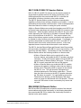
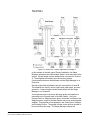
TYPICAL APPLICATIONS
CABLE OR SCHOOL TELEVISION STUDIO
Figure 1-7: Party Line Studio Application
The typical Cable or School Television Studio installation shown in the
preceding diagram is centered around a two-channel Main Station,
which also powers the system. The Director operates this station and
an Assistant Director operates a two-channel Remote Station. A line
of single-channel beltpacks is connected to Channel A. The beltpacks
are used by camera operators and floor managers. Communication
between these people and the Director and Assistant Director is on
Channel A. Two-channel Headset Stations are wired to both channels
A and B and are used by the video and graphics people. This allows
them the flexibility of communicating on either Channel A or Channel
B.
Program feed audio is connected to the Remote Station so it can be
heard by the Director as well as the Talent and Announcers. A Call
Clear-Com Communication Systems
Encore System Installation Instruction Manual
1-15
signal can interrupt the program audio that feeds into the Remote
Station. Talent and Announcers use Talent Receivers which are
connected to Channel B. The Director and Assistant Director must be
able to interrupt this program audio to cue the Talent and Announcers,
so Channel B would be programmed as follows:
• The Momentary Talk B option switch on the Main and Remote
Stations must be set to the ON (down) position. This will
cause the Channel B Talk button to have a momentary only
action and not latch. Refer to the appropriate User Manuals
for the location of these settings.
• The Call on Talk B option switch on the Main and Remote
Stations must be set to the ON (down) position. This will
cause the Channel B Talk button to activate the Call signal.
• The Channel B On-Off-Interrupt switch on the Remote Station
must be set to the INTERRUPT position. The Channel A
On-Off-Interrupt switch must be set to the OFF position,
assuming that program audio should not be heard on this
channel.
• The Channel B Program Level trimpot on the Remote Station
should be adjusted so that the program feed is at a
comfortable level for the Talent and Announcer.
If desired, the Director could turn on the Party Line Link (A+B) switch
on the Main Station during rehearsals to combine the communication
between everyone on both channels.
The Main or Remote Station speaker can be turned on whenever
necessary, when others in the area need to hear. If it is turned on, it
will automatically dip in level whenever the panel or headset
microphone is on.
A PA amplifier can be connected to the Announce Output of the Main
Station, allowing the Director to make announcements to everyone in
the studio. The Relay Out connection can be used to switch the PA
amplifier if necessary. Depending upon the situation, these
announcements may tend to interfere with communication on the
intercom line. If this is a problem, set the Interrupt Announce Option
Switch on the Main Station to the ON position. This will prevent
announcements from being heard on the intercom line.
Although this application was illustrated using 2-channel Main and
Remote Stations, it could have been implemented using 4-channel (or
more) stations. Doing so could further split the functional areas and
allow more individual conversations to occur at once.
1-16
Clear-Com Communication Systems
Encore System Installation Instruction Manual
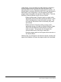
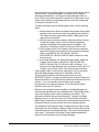
THEATRE 1
Figure 1-8: Party Line Theatre Application Example 1
In the preceding diagram of a typical Theatre installation, the Stage
Manager operates a two-channel Main Station, which also powers the
system. Several single-channel beltpacks are connected to Channel
A. The beltpacks are used by curtain, spot, patch panel, and light
board operators. Communication between these people and the Stage
Manager is on Channel A.
Some Main Stations contain a Tone Alert function. This will audibly
signal the Stage Manager if the stage personnel press the Call buttons
on their beltpacks. If needed, the Tone Alert function can be enabled
using the button on the front panel. The volume of this signal can be
set using the Tone Alert Volume control.
An audio mixing console output from the stage pickup microphones is
connected to the Program Input of the Main Station. If desired, this
audio can be placed at a low (or any) level on Channel A. The level
can be adjusted using the Channel A Program Level trimpot. If this
Clear-Com Communication Systems
Encore System Installation Instruction Manual
1-17
audio is to be interrupted by communication from the Stage Manager,
then the Channel A On-Off-Interrupt switch should be set to the
INTERRUPT position. If stage microphone audio should be heard on
Channel A at all times, the On-Off-Interrupt switch should be set to the
ON position. If it is not desirable to have audio from the stage
microphones on this intercom channel, the On-Off-Interrupt switch
should be set to the OFF position.
The Program Level control can be used to adjust the stage
microphone audio level the Stage Manager hears. If or whenever the
Stage Manager does not need to monitor this, the Program Level
control can be turned fully counter-clockwise.
Channel B is connected to Speaker Stations such as the Clear-Com
KB-112/KB-212/KB-701 which are installed in the green room and in
dressing rooms. These Speaker stations should be optioned for
Normal operation, which enables the speaker and allows a
push-to-talk function for replying to the Stage Manager. Channel B on
the Main Station would typically be programmed as follows:
• The Momentary Talk B option switch must be set to the ON
position. This will cause the Channel B Talk button to have a
momentary only action and not latch. The Stage Manager
could then only be heard by the actors and actresses in the
Green Room and Dressing Rooms when the Channel B Talk
button is held down.
• The Channel B On-Off-Interrupt switch must be set to the
INTERRUPT position. This causes the Channel B Talk button
to interrupt the audio from the stage microphone.
• The Channel B Program Level trimpot should be adjusted to a
comfortable level in the Speaker Stations.
The stage microphone audio can then be heard by the actors and
actresses in the green room and dressing rooms. The stage
microphone audio heard by the waiting actors and actresses will be
interrupted whenever the Stage Manager talks to them.
Because of the two-channel capability, communication between the
Stage Manager and stage equipment operators cannot be heard by the
actors and actresses, and vice-versa. This eliminates confusion and
miscommunication. If desired, the Stage Manager can turn on the
Party Line Link (A+B) switch on the Main Station during rehearsals to
combine the communication between everyone on both channels.
1-18
Clear-Com Communication Systems
Encore System Installation Instruction Manual
THEATRE 2
Figure 1-9: Party Line Theatre Application Example 2
In this example of another typical Theatre installation, the Stage
Manager operates a two-channel Main Station, which also powers the
system. Several single-channel beltpacks are connected to Channel
A. The beltpacks are used by props and scenery people.
Communication between these people and the Stage Manager is on
Channel A.
Several single-channel beltpacks are also connected to Channel B.
The beltpacks are used by sound, light board, patch panel, and spot
operators. Communication between these people and the Stage
Manager is on Channel B.
A mixing board audio output from the stage pickup microphones is
connected to the Program Input of the Main Station. Using the
Program Audio to Stage Announce option, this audio is routed out the
Stage Announce output of the Main Station and into an external power
amplifier. This amplifier drives speakers in the Green Room, Hallways,
and Dressing Rooms. The people in these rooms will then be able to
hear sound from the stage. The Stage Manager presses the
Clear-Com Communication Systems
Encore System Installation Instruction Manual
1-19
Announce button on the Main Station to communicate with the people
in these rooms. When this happens, the audio from the stage is
interrupted automatically. As long as the Stage Manager does not
have a Talk set, the announcement is heard only by the people in the
Green Room, Hallways, and Dressing Rooms, but not by the people
on intercom Channels A or B.
To adjust the stage announce and program levels, use the following
steps:
1. Press the Announce button and adjust the program audio power
amplifier for the correct level from the speakers connected to it.
The Stage Announce output will provide a 0 dBu signal to the
stage announce amplifier.
2. With the Announce button released, adjust the Mixing Console
so that the Program level is correct as heard through the
speakers connected to the stage announce amplifier. The
output from the Mixing Console will likely be 0 dBu or less.
3. If the Program Audio is to be heard on the intercom channels,
adjust the Program Level controls for the channels accordingly.
Refer to the MS-232, MS-702, MS-440, RM-440,
MS-704/RM-704, SB-440 or SB-704 Station manual to locate
these controls.
4. If the Stage Manager is to hear the Program Audio, adjust the
Program Level control on the MS-232, MS-702, MS-440,
MS-704, RM-440, RM-704, SB-440 or SB-704 Station. If or
whenever the Stage Manager does not need to monitor this, the
Program Level control can be turned fully counter-clockwise.
If the program audio on the intercom channel(s) is to be interrupted
when the Stage Manager presses the Talk button, then the
On-Off-Interrupt switch for that channel should be set to the
INTERRUPT position. If stage microphone audio should be heard on a
channel at all times, its On-Off-Interrupt switch should be set to the ON
position. If it is not desirable to have audio from the stage
microphones on an intercom channel, its On-Off-Interrupt switch
should be set to the OFF position.
Because of the multiple-channel capability, the Stage Manager can
communicate individually to three separate areas: Props and Scenery,
Sound and Lighting, and Costuming, Makeup, and Talent. This
eliminates confusion and miscommunication. If desired, the Stage
Manager can turn on the Party Line Link (A+B) switch on the Main
Station during rehearsals to combine the communication between the
Props and Scenery channel and the Sound and Lighting channel.
The drawback of the Program Audio to Stage Announce option is that
the people in the Green Room, Hallways, and Dressing rooms cannot
communicate back to the Stage Manager. This may not be drawback
in all cases. The benefit of this option is that it adds an additional
channel of communication from the Stage Manager.
1-20
Clear-Com Communication Systems
Encore System Installation Instruction Manual
ENG/EFP TRUCK
Figure 1-10: Party Line Eng/EFT Truck Application
In the preceding diagram of a typical ENG/EFP Truck installation, a
2-Channel Main Station powers the intercom system. The Director
operates the Main Station, and an Engineer operates the Remote
Station. A line of single-channel beltpacks is connected to Channel A
and are used by camera operators and floor managers.
Communication between these people and the Director is on Channel
A. If 4-channel (or more) stations were used in this application, the
functional areas of communications could be further split to allow more
individual conversations to occur at once.
A System Interface such as the Clear-Com TW-12C can be used to
interconnect with another intercom system which may be on site,
whether or not it is a Clear-Com system. It isolates the intercom audio
and compensates for level and impedance differences. It also isolates
and translates call signals. A Clear-Com Telephone Interface can be
used to provide a studio feed over a dial-up telephone line. The
Telephone Interface should be optioned to insert program on Channel
B, and interrupt the program when a Call signal is present on Channel
B. Because the program audio is fed into the intercom line and not the
Clear-Com Communication Systems
Encore System Installation Instruction Manual
1-21
Program Input jack, the Program Level controls on the Main Station
have no effect.
Channel B is connected to a Talent Receiver for Talent or an
Announcer. Program feed audio from the studio feed can be heard by
the Director and Engineer, as well as the Talent or Announcer. The
Call on Talk B and Momentary Talk B options switches on the Main and
Remote Stations would be set to the ON (down) position . This would
cause the program audio heard by the Talent and Announcer to be
interrupted whenever the Director talks to them, but only while the
Director is holding the Talk button.
1-22
Clear-Com Communication Systems
Encore System Installation Instruction Manual
SYSTEM CHECKOUT
Before you turn on the power, perform the following tests:
CHECK TERMINATION
There should be one and only one termination for each channel in the
system. This termination is usually set to ON at the Main Station or
Power Supply. To ascertain that only one termination is present on the
channel, perform the following test:
Note: The location of the termination switch varies with model.
On some products, the termination switches are on the rear
panel; on others they are jumpers inside the unit. Consult
the unit's manual for the location.
1. Using a multimeter, measure the resistance between pins 1 and
3 on one of the Channel A XLR connectors at the rear of the
unit.
2. If the channel is terminated properly, then the resistance should
measure approximately 4,000 Ohms. A very high channel
resistance means the channel is not terminated. Channel
resistance of 2,000 Ohms indicates a double-termination. If a
double-termination is indicated, locate the other terminated
Power Supply or Main Station and set its termination to OFF.
3. Repeat for the other channels.
4. Check resistance between Chassis Ground and pin 1. Using an
Ohmmeter, measure the resistance from pin 1 on the Main
Station or Power Supply to chassis ground. The measurement
should read 10 Ohms. A high reading (over 100 Ohms)
indicates that the 10 Ohm resistor in the unit has failed and
requires replacement. Failure to perform the replacement will
result in an audible "buzz" in the system. A reading of less than
10 Ohms (or a short) typically indicates that the shell and pin 1
of one of the interconnect cables are shorted together. Test
the individual cables until the culprit is located and repair or
replace the cable.
Note: Pin 1 and the shell of the XLR plug on the interconnect
cables should NOT be connected together.
CHECK INTERCOM CABLE RESISTANCE
For minimal crosstalk, the ground resistance of the intercom cables
should be as low as possible, preferably less than 2 Ohms.
Disconnect an intercom line from the Main Station or Power Supply.
At the point in the intercom line furthest from the unit, connect a clip
lead jumper between pins 1 and 2. Back at the "powered" end, use an
Ohmmeter to measure the resistance between pins 1 and 2. A value
of less than 4 Ohms is ideal, but a value of 4 to 10 Ohms is acceptable.
Clear-Com Communication Systems
Encore System Installation Instruction Manual
1-23
FINAL TESTS
After you turn the power ON:
1. Check for proper voltage on pin 2 of any intercom line or jack in
a channel. It should read 26-30 Volts.
2. Test for proper operation of Call Signaling. Activate the Call
Signal on any beltpack or station. The call light on the Main
Station should illuminate and then go out when the call button is
released. If enabled, the Tone Alert should sound. Activate the
Call Signal on the Main Station. The call lights on any beltpacks
or stations should illuminate and then go out when the call
button is released.
3. Adjust the sidetone on this and all stations. (Refer to the manual
for each specific unit for instructions.) Using the headset or
panel mic, make sure that the Main Station can communicate
with attached beltpacks or stations. Check that other stations
can be heard through the panel speaker.
4. If connected, check that Program Input, Announce Output and
Hot Mic Output / IFB System jacks are functional. Verify the
operation of the controls that affect the function of these inputs
and outputs. Refer to the User Manual of the particular Main
Station.
1-24
Clear-Com Communication Systems
Encore System Installation Instruction Manual
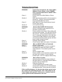
TROUBLESHOOTING
PROBLEM:
Cause 1:
Solution 1:
Cause 2:
Solution 2:
PROBLEM:
Cause 1:
Solution 1:
Cause 2:
Solution 2:
PROBLEM:
Cause 1:
Solution 1:
Cause 2:
Solution 2:
PROBLEM:
Cause 1:
Solution 1:
Cause 2
Solution 2:
System does not operate. No power to Main
Station or Power Supply. Green POWER
LED is not illuminated and no SHORT LED's
are illuminated
No AC power to the Main Station or Power
Supply.
Make sure the power switch on the rear panel is
turned ON. Check AC connection and cable.
Plug into dependable AC source.
Main Station or Power Supply has an internal
Power Supply failure.
Unit requires servicing.
Problem:Red SHORT LED illuminated
Short or overload on that channel due to a
shorted or miswired cable.
Remove cables one at a time from system until
the faulty line is located. (The red Short LED will
then turn off.) Check for shorts between pins 1
and 2 or improper cable wiring. Once the short
is removed, the Main Station or Power Supply
will reset automatically and the power will come
back up within several seconds.
Defective Remote Station.
Check Remote Station and replace if necessary.
Both red SHORT LEDs are illuminated
System is overloaded.
Remove cables, one at a time from system to
help determine where the excess current
requirements lie. Re-evaluate system current
needs.
Short in multipair cable.
Remove cables, one at a time from system until
the faulty line is located. Check for shorts
between pins 1 and 2 or improper cable wiring.
Hum or buzz in system
Inductive pickup caused by close proximity of
this Main Station or connected Remote Stations
to power lines or transformers.
Relocate offending unit.
10 Ohm chassis ground resistor is open.
Check the DC resistance for 10 Ohms between
the chassis and pin 1 of any intercom connector.
If this condition happens, it is because the system ground came
into contact with something that was "HOT" with respect to the
Power Supply earth ground. If this occurs, carefully check the
system ground and AC distribution in the area.
Clear-Com Communication Systems
Encore System Installation Instruction Manual
1-25
Warning:This is a potentially dangerous situation. A shock hazard
may exist between the metal boom of a Remote Station
headset and ground.
PROBLEM:
Cause 1:
Solution 1:
Cause 2:
Solution 2:
Cause 3:
Solution 3:
Cause 4:
Solution 4:
PROBLEM:
Cause 1:
Solution 1:
Cause 2:
Solution 2:
Cause 3:
Solution 3:
Excessive crosstalk
High DC resistance in ground return.
Use heavier cable; add additional conductor(s)
to ground return.
MULTI-CHANNEL cable pairs are not
individually shielded.
Replace cable with individually shield pairs.
Headset cables are not wired properly or
shielded properly.
Correct wiring. Use headsets with properly
shielded wiring.
PROBLEM:
Cause:
Solution:
Program signal sounds distorted.
Overload of Program Input circuit.
Reduce Program Input level or reduce the gain
of the program signal at the source, such as an
audio mixer.
PROBLEM:
Cause 1:
Solution 1:
Call signals do not function.
Excessive DC loading of intercom line.
Remove any audio transformers or other
equipment which may be connected across the
intercom line. If equipment other than
Clear-Com intercom equipment must be
connected to the intercom line, please contact
Clear-Com application or service personnel for
advice.
Far too many terminations on the intercom line.
Check all Main Stations and Power Supplies to
make sure each intercom channel is terminated
at only one point .
Cause 2:
Solution 2:
1-26
System feedback (Acoustical)
Listen Level control at this station or a Remote
Station is set too high.
Adjust.
Sidetone Null control at this station or a Remote
Station is not adjusted correctly.
Adjust. Refer to the procedure in the Front
Panel Controls section of this manual.
Channel unterminated.
Set the Main Station or Power Supply
termination switch for that channel to the ON
position.
A headset extension cord was used.
Headset extension cords are not recommended.
Clear-Com Communication Systems
Encore System Installation Instruction Manual
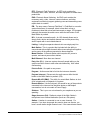
GLOSSARY
Some of the terms used when discussing critical communications for
television or theatre may be new to you as they are unique to intercom
applications. Although many of the terms are common to other audio
applications, to be certain you understand their meanings we offer the
following definitions:
All Call: Ability to push one button from the Main Station and talk to all
channels at once on a multiple channel system.
Ambient Noise: Those background sounds which are not part of the
specific communication but are picked up by the microphone.
Selection of a good "noise-canceling" mic will reduce ambient noise.
Belt Pack: A portable electronics package worn on the belt or
mounted on a wall or other convenient location. Interconnects to
system with mic cable and is powered by a central Power Supply or
Main Station.
Bridging, High Impedance (hi-Z): A method of connecting to an
audio line (such as Clear-Com) without loading or taking appreciable
power from that line. Simply stated, as you add more and more
stations to the line, the volume remains constant.
Call Signaling: This feature is included with the majority of
Clear-Com products. It is a visual indicator on a station (a lamp or
LED) used to attract the attention of an operator who has removed the
headset.
Channel: A channel is the line that connects parties together within a
party line - it is a two-way talk path. For example, if you have six
people who need to hear one director, you have a seven-station
single-channel need. If the same director needs to speak privately to
any one of the six, add a second channel. You now have a
seven-station, two-channel system.
Closed-Circuit: Any intercom which is connected via cable (also
called hard-wired). The other type would be Wireless. . .we make
those too. However, if you want privacy and versatility, you probably
want a closed-circuit system or a combination of both.
Cross Talk: Leakage of audio transmissions from one channel to
another.
Dry Pair: A telephone term is used to describe a pair of wires (2
conductors) that carry audio but no voltage. Contrast this with a "Wet
Pair" that carries both audio and voltage.
Duplex: Duplex refers to bi-directional communications. Normal
communication between individuals talking face to face is "full duplex"
-- in other words you can talk and listen simultaneously. The
alternative is "half-duplex" such as a push-to-talk situation where one
station at a time can talk while others listen. A walkie-talkie is a good
example of half-duplex communication.
Clear-Com Communication Systems
Encore System Installation Instruction Manual
1-27
EFP: Electronic Field Production. An EFP truck contains the
necessary audio, video, intercom, and other equipment to create these
productions.
ENG: Electronic News Gathering. An ENG truck contains the
necessary audio, video, intercom, communications, and other
equipment to effectively support gathering news and transmitting news
reports back to a studio.
IFB: The term means "Interrupt Fold Back." A Fold-Back is a monitor
system that allows, for example, talent to hear their voices or
musicians to hear their voices and instruments on stage. IFB (program
interrupt) disconnects the audio source while the talk button on the
Main Station is pushed.
ISO: A private conversation path. An ISO channel allows one to
simply push a button and transfer themselves and the person they
wish to speak with to an isolated channel.
Linking: Linking ties separate channels into one single party line.
Main Station: This is a product that includes both the ability to
communicate with multiple channels without connecting them together,
and to power all the stations connected to these channels.
Master Station: A Remote Station which requires AC power to
operate, and cannot power other stations
Multi-Channel: More than one channel
Party Line (P.L.): Intercom system where all people talking on the
system can talk or listen to each other simultaneously. Also called
conferencing.
Point to Point: One path to one person.
Program: Audio source that is fed into the intercom channels.
Program Interrupt: Disconnects the audio source while the talk
button on the Main Station is pushed. (IFB)
Remote Mic Kill (RMK): The ability for certain Main Stations to shut
off all microphones on beltpacks in a system.
Remote Station: Like the belt pack, this would be any of the products
connected to the intercom line that allow duplex or half-duplex
conversation, but do not contain a Power Supply.
Sidetone: This is your own voice heard in your earphone as you are
speaking.
Stage Announce (SA): Redirects output of the Main Station's
microphone to an external destination (such as a PA system).
Station: A station is connected to one or more channels. For
example, if you have six people who need to hear one director, you
have a seven-station single-channel need. If the same director needs
1-28
Clear-Com Communication Systems
Encore System Installation Instruction Manual
to speak privately to any one of the six, add a second channel. You
now have a seven-station, two-channel system.
Termination: Passive network that is connected in each channel,
usually on the Power Supply or Main Station.
Clear-Com Communication Systems
Encore System Installation Instruction Manual
1-29
1-30
Clear-Com Communication Systems
Encore System Installation Instruction Manual
2
CONFIGURATION
OPTIONS
PARTY LINE PRODUCTS
The following table provides information on Party Line products
indicating which model numbers have similar functionality to assist in
upgrading existing systems where the current products are no longer
available. As the functionality of the equivalent products may be
slightly different the user should check the product manuals for details.
DESCRIPTION
Clear-Com Communication Systems
Encore System Installation Instruction Manual
ENCORE
PRODUCT
PARTY LINE
PRODUCT
2-Channel Main Station
MS-702
MS-232,
MS-222,
MS-200
2-Channel Remote Station
RM-702
RM-220
2-Channel Portable Station
CS-702
CS-222
4-Channel Main Station
MS-704
MS-440,
MS-400A
4-Channel Remote Station
RM-704
RM-440
4-Channel Switchboard Main
Station
SB-704
SB-440,
SB-412A
12-Channel Programmable
Main Station
MS-812A
MS-812A
12-Channel Source
Assignment Panel
RCS-2700
RCS-2000
Amplified Monitor Speaker
AMS-1027
AMS-1025
Single Channel Wall Mount
Speaker Station
KB-701
KB-212, KB112
2-Channel Wall Mount
Speaker Station
KB-702
KB-702GM
KB-211
KB-211GM
2-1
DESCRIPTION
ENCORE
PRODUCT
PARTY LINE
PRODUCT
2-Channel Wall Mount
Headset Station
HB-702
MR-202
4-Channel Wall Mount
Headset Station
HB-704
MR-704
2-Channel Power Supply
PS-702
PS-232
4-Channel Power Supply
PS-704
PS464
Program Interrupt Controller
PIC-4704
PIC-4000
System Interface
TWC-12C
TWC-12B
4-Wire Interface
IF4W4
IF4B-2
IF4B-4
2-Channel Intercom Adapter
TWC-701
4-Channel Intercom Adapter
TWC-704
2-Way Radio Interface
TW-47
TW-40
Party Line to 4-Wire Interface
EF-701M
EF-1M
Telephone and 2-Wire
Interface
AC-701
AC-10H
Call Signal Flasher
FL-7
FL-1
Lightweight Power Supply
PK-7
PK-5
IFB Control Panel
AX-704
AX-4
IFB Control Panel with Mic
Connector
MA-704
MA-4
Talent Receiver
TR-50
TR-50
Announcer’s Console
AB-700
AB-100
Beltpacks
RS-601/RS-602
/RS-622/RS-60
3/RS-603R/RS623/RS-623R
RS-501,
RS-502,
RS-522
Table 2-1: Party Line Product Equivalences
2-2
Clear-Com Communication Systems
Encore System Installation Instruction Manual
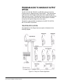
PROGRAM AUDIO TO ANNOUNCE OUTPUT
OPTION
The MS-232, MS-440, RM-440, and SB-440 products include the
Program Audio to Stage Announce Output option. This option allows
audio from the main Program Audio input to be routed through the
Stage Announce output. Pressing the Announce button interrupts this
audio and instead routes audio from the selected panel or headset
microphone through the Stage Announce output.
This facility is also available as standard on the MS-702, MS-704,
RM-704 and SB-704 products.
THEATRE APPLICATION
One application of the Stage Announce option is illustrated in the
following diagram:
Figure 2-1: Party Line Theatre Application
Clear-Com Communication Systems
Encore System Installation Instruction Manual
2-3
In the preceding diagram of a typical Theatre installation, the Stage
Manager operates a two-channel Main Station, which also powers the
system. Several single-channel beltpacks are connected to Channel
A. The beltpacks are used by props and scenery people.
Communication between these people and the Stage Manager is on
Channel A.
Several single-channel beltpacks are also connected to Channel B.
The beltpacks are used by sound, light board, patch panel, and spot
operators. Communication between these people and the Stage
Manager is on Channel B.
A mixing board audio output from the stage pickup microphones is
connected to the Program Input of the Main Station. Using the
Program Audio to Stage Announce option, this audio is routed out the
Stage Announce output of the Main Station and into an external power
amplifier. This amplifier drives speakers in the Green Room, Hallways,
and Dressing Rooms. The people in these rooms will then be able to
hear sound from the stage. The Stage Manager presses the
Announce button on the Main Station to communicate with the people
in these rooms. When this happens, the audio from the stage is
interrupted automatically. As long as the Stage Manager does not
have a Talk set, the announcement is heard only by the people in the
Green Room, Hallways, and Dressing Rooms, but not by the people
on intercom Channels A or B.
If desired, the stage audio can be placed at a low (or any) level on
Channel A and/or Channel B. The level can be adjusted using the
Program Level trimpots for each channel. If this audio is to be
interrupted whenever the Stage Manager presses the Talk button, then
the On-Off-Interrupt switch for that channel should be set to the
INTERRUPT position. If stage microphone audio should be heard on a
channel at all times, its On-Off-Interrupt switch should be set to the ON
position. If it is not desirable to have audio from the stage
microphones on an intercom channel, its On-Off-Interrupt switch
should be set to the OFF position.
The Program Level control can be used to adjust the program audio
level the Stage Manager hears. If or whenever the Stage Manager
does not need to monitor this, the Program Level control can be turned
fully counter-clockwise.
Because of the multiple-channel capability, the Stage Manager can
communicate individually to three separate areas: Props and Scenery,
Sound and Lighting, and Costuming, Makeup, and Talent. This
eliminates confusion and miscommunication. If desired, the Stage
Manager can turn on the Party Line Link (A+B) switch on the Main
Station during rehearsals to combine the communication between the
Props and Scenery channel and the Sound and Lighting channel.
The drawback of the Program Audio to Stage Announce option is that
the people in the Green Room, Hallways, and Dressing rooms cannot
communicate back to the Stage Manager. This may not be drawback
2-4
Clear-Com Communication Systems
Encore System Installation Instruction Manual
in all cases. The benefit of this option is that it adds an additional
channel of communication from the Stage Manager.
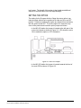
SETTING THE OPTION
The setting for the Program Audio to Stage Announce option is an
internal jumper which may be positioned in either an ON or an OFF
position. Products containing this option are shipped from the factory
with the option turned OFF. To turn the option on, remove the top
cover of the product and locate the option jumper as follows:
• In the MS-232 station the jumper is located at the left rear of the
main circuit board as shown in Figure 2-2. JP2 should be set to
ON to enable the option or OFF to disable it.
Figure 2-2: MS-232 Jumper
• In the MS-702 station the jumper is located towards the front of
the main PCB as shown in Figure 2-3.
Clear-Com Communication Systems
Encore System Installation Instruction Manual
2-5
Figure 2-3: MS-702 Jumpers
• In the MS-440, MS-704, RM-440, RM-704, SB-440 and SB-704
stations, the jumper is located near the middle of the main circuit
board. J11 should be set to ON to enable the option or OFF to
disable it.
SYSTEM SETUP
After connecting the MS-232, MS-702, MS-440, MS-704, RM-440,
RM-704, SB-440 or SB-704 Station, perform the following steps to
assure that the audio level will be correct at each listening point:
1. Press the Announce button and adjust the stage announce power
amplifier for the correct level from the speakers connected to it.
The Stage Announce output will provide a 0 dBu signal to the
stage announce amplifier.
2. With the Announce button released, adjust the Mixing Console so
that the Program level is correct as heard through the speakers
connected to the stage announce amplifier. The output from the
Mixing Console will likely be 0 dBu or less.
3. If the Program Audio is to be heard on the intercom channels,
adjust the Program Level controls for the channels accordingly.
Refer to the MS-232, MS-702, MS-440, MS-704, RM-440,
RM-704, SB-440 or SB-704 Station manual to locate these
controls.
4. Lastly, if the Stage Manager is to hear the Program Audio, adjust
this level on the MS-232, MS-702, MS-440, MS-704, RM-440,
RM-704, SB-440 or SB-704 Station.
2-6
Clear-Com Communication Systems
Encore System Installation Instruction Manual
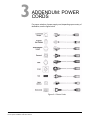
3
ADDENDUM: POWER
CORDS
For proper selection of power supply cord, depending upon country of
destination, see the figure below.
Figure 3-1: Power Cords
Clear-Com Communication Systems
Encore System Installation Instruction Manual
3-1
3-2
Clear-Com Communication Systems
Encore System Installation Instruction Manual
LIMITED WARRANTY
This document details the Clear-Com Standard Limited Warranty for all new products for sale within all
regions with the exception of Military, Aerospace, and Government (MAG).
EXCEPT AS SET FORTH HEREIN ("LIMITED WARRANTY"), CLEAR-COM MAKES NO OTHER
WARRANTIES, EXPRESS, IMPLIED OR STATUTORY, INCLUDING WITHOUT LIMITATION ANY
WARRANTIES OF MERCHANTABILITY, NONINFRINGEMENT OF THIRD PARTY RIGHTS, OR
FITNESS FOR A PARTICULAR PURPOSE, ALL OF WHICH ARE EXPRESSLY DISCLAIMED.
1. Standard Limited Warranty. Clear-Com Communication Systems ("Clear-Com") warrants its
products, including supplied accessories, against defects in material or workmanship for the time
periods as set forth below provided it was purchased from an authorized Clear-Com dealer or
distributor.
a) Pursuant to this Limited Warranty, Clear-Com will, at its option:
i)
repair the product using new or refurbished parts, or;
ii) replace the product with a new or refurbished product.
b) Remedies: In the event of a defect, the rights detailed in 1 (a) are your exclusive remedies. For
purposes of this Limited Warranty, "refurbished" means a product or part that has been returned
to its original specifications.
c) Standard Warranty Period (by Product):
i)
All Clear-Com brand systems and products, including belt packs, have a Limited Warranty
of two years, with the exception of;
(1) Cables, accessories, components & consumable items have a Limited Warranty of 90
days.
(2) Any Clear-Com product that has been classified as obsolete at the time of sale has a
Limited Warranty of 90 days from sales and will be replaced with the same product or a
sales credit will be issued, at the sole discretion of Clear-Com.
(3) Headsets, handsets, microphones, and associated spare parts, as well as UHF wireless
IFB products, have a Limited Warranty of one year.
(4) UHF WBS Analog wireless intercom systems have a Limited Warranty of three years.
Clear-Com Communication Systems
Standard Limited Warranty
i
(5) All software products, including Concert (Client and Server), ECS, Production Maestro
and Logic Maestro are warranted for one year and shall substantially conform to
published specifications. The media on which the Software is furnished is warranted to
be free of defects in material and workmanship (under normal use) for a period of one
year.
(6) Any Clear-Com products that are listed within the last time buy period have the same
Limited Warranty for their type 1.i 1 - 1.i.5 as above.
d) Any Clear-Com product that is repaired or supplied as a replacement under the terms of this
Limited Warranty shall inherit the remaining warranty period from the original product.
e) Standard Warranty Period Start Date
i)
Dealer / Distributor Sales: In view of Dealer or Distributor stocking practices, the Standard
Warranty Period for products sold through Dealers or Distributors will commence from the
Clear-Com invoice date and will include an automatic extension of three months. Any valid
warranty claim within the Standard Warranty Period as determined by the Clear-Com
invoice date will be covered without further supporting evidence. All warranty claims after
this date must be supported by the Customer's proof of purchase that demonstrates the
product is still within the Standard Warranty Period (as detailed in Section 1.c.i above, plus
the automatic three month extension) from their purchase date.
ii) Direct Sales: The Standard Warranty Period will commence from the date the product was
shipped from Clear-Com to the Customer. The Standard Warranty Period start date for
contracts that include commissioning will be the date of the Site Acceptance Test (SAT) or
one month from conclusion of the commissioning project, whichever is earlier.
f) Invalidation of Warranty
i)
This Limited Warranty shall be invalidated if the product's outer case has been opened and
internal modifications have been made or damage has occurred, or upon the occurrence of
other damage or failure not attributable to normal wear and tear. Authorized modifications
with Clear-Com's express written permission will not invalidate the warranty.
g) Software Updates
i)
ii
Software Updates are released periodically to correct discovered program bugs. During the
Warranty Period, software updates are available to Customers free of charge.
Clear-Com Communication Systems
Standard Limited Warranty
h) Software Upgrades
i)
Software Upgrades include new Features and/or Functional Enhancements and are not
included as part of the Standard Warranty but may be purchased at the published rates.
ii) Note: In the absence of a Software Update containing a program correction and no
available workaround to mitigate the problem, at the discretion of Service, Sales,
Engineering, or Product Management, the Customer may be provided a Software Upgrade
under warranty.
2. Exclusions. Services do not cover damage or failure caused by any occurrence beyond Clear-Com's
reasonable control, including without limitation acts of God, fire, flooding, earthquake, lightning, failure
of electric power or air conditioning, neglect, misuse, improper operation, war, government
regulations, supply shortages, riots, sabotage, terrorism, unauthorized modifications or repair, strikes,
labor disputes or any product failure that Clear-Com determines is not a result of failure in the
Services provided by Clear-Com. Further Services excluded from this Agreement include: services
required due to errors or omissions in Customer purchase orders; installation or maintenance of
wiring, circuits, electrical conduits or devices external to the products; replacement or reconditioning
of products which, in Clear-Com's opinion cannot be reliably maintained or properly serviced due to
excessive wear or deterioration; Customer's failure to maintain the installation site in accordance with
the environmental specifications of the products; or service on products removed from the location
originally specified by Customer and/or reinstalled without the prior written approval of Clear-Com.
Customer will pay Clear-Com's then current published charges to restore such Covered Products to a
condition eligible for further service under this Agreement. Clear-Com shall be excused from and shall
not be liable for any failure or delay in performance under this Agreement due to the foregoing or any
causes beyond its reasonable control.
3. Limitation of Liability. IN NO EVENT WILL CLEAR-COM BE LIABLE UNDER THIS AGREEMENT
FOR ANY INDIRECT, SPECIAL, INCIDENTAL OR CONSEQUENTIAL DAMAGES (INCLUDING
WITHOUT LIMITATION LOST PROFITS), REGARDLESS OF THE FORM OF ACTION, EVEN IF
ADVISED IN ADVANCE OF THE POSSIBILITY OF SUCH DAMAGES.
4. Assignment. Neither party may assign this Agreement or any portion thereof without the prior written
consent of the other, except in the event of a merger, sale of all or substantially all of the assets or
other corporate reorganization.
5. Ownership of replaced parts or product. All replaced parts or products become the property of
Clear-Com.
6. Entire Agreement. This Agreement constitutes the entire agreement between the parties with
respect to the subject matter hereof, and supersedes all prior or contemporaneous proposals, oral or
written, and all other communications between them relating to the subject matter of this Agreement.
Clear-Com Communication Systems
Standard Limited Warranty
iii
iv
Clear-Com Communication Systems
Standard Limited Warranty
TECHNICAL SUPPORT & REPAIR POLICY
NOVEMBER 1, 2008
In order to ensure that your experience with Clear-Com and our World Class products is as beneficial,
effective and efficient as possible, we would like to define the policies and share some "best practices"
that can accelerate any problem solving processes which we may find necessary and to enhance your
customer service experience. Our Technical Support, Return Material Authorization, and Repair Policies
are set forth below. These Policies are subject to revision and constantly evolve in order to address our
Customers' and the Market's needs. Accordingly these are provided by way of guidance and for
information only and may be changed at anytime with or without Notice.
TECHNICAL SUPPORT POLICY
a) Telephone, online, and e-mail technical support will be provided by the Customer Service Center
free of charge during the Warranty Period.
b) Technical support will be provided free of charge for all software products under the following
conditions:
i)
The application, operating, and embedded software is installed on a product covered by
Clear-Com's Limited Warranty, and:
(1) The software is at the current release level; or,
(2) The software is one (1) version removed from current.
ii) Older versions of software will receive "best-effort" support, but will not be updated to
correct reported bugs or add requested functionality.
c) For Technical Support:
i)
North and South America, (inc. Canada, Mexico, and the Caribbean) & US Military:
Hours:
0800 - 1700 Pacific Time
Days:
Monday - Friday
Tel:
+1 510 337 6600
Email:
[email protected]
ii) Europe, the Middle East and Africa:
Hours:
0800 - midnight Central European Time
Clear-Com Communication Systems
Technical Support & Repair Policy
v
Days:
Tel:
Email:
iii) Asia-Pacific:
Hours:
Days:
Tel:
Email:
Monday - Friday
+49 40 853 999 700
[email protected]
0800 - 1700 Pacific Time
Monday - Friday
+1 510 337 6600
[email protected]
d) Email Technical Support is available for all Clear-Com branded products free of charge for the life
of the product, or two years after a product has been classified as obsolete, whichever comes
first.
e) Support for Distributor and Dealer Sales
i)
Distributors and Dealers may utilize the Customer Service Centers once a system has been
installed and commissioned. Clear-Com Systems and Applications Engineers will provide
support to the Distributor from the pre-sales stage through to satisfactory installation for new
system purchases. Customers will be encouraged to contact their Dealer or Distributor with
their installation and technical support enquires rather than using the Customer Service
Centers directly.
f) Support for Direct Sales
i)
Customers may utilize the Customer Service Centers once a system has been installed and
commissioned by Clear-Com Systems and Applications Engineers, or in the case of project
installations, once the Project Team has completed the hand-over to the Support Centers.
RETURN MATERIAL AUTHORIZATION POLICY
a) Authorizations: All products returned to Clear-Com or a Clear-Com Authorized Service Partner
must be identified by a Return Material Authorization (RMA) number.
b) The Customer will be provided with an RMA number upon contacting Clear-Com Sales Support
as instructed below.
c) The RMA number must be obtained from Clear-Com via phone or email prior to returning product
to the Service Center. Product received by the Service Center without a proper RMA number is
subject to return to the Customer at the Customer's expense.
vi
Clear-Com Communication Systems
Technical Support & Repair Policy
d) Damaged equipment will be repaired at the Customer's expense.
e) Returns are subject to a 15% restocking fee.
f) Advance Warranty Replacements (AWRs);
i)
During the first 30 days of the Standard Warranty Period: Once the equipment fault has
been verified by Clear-Com or its authorized representative, Clear-Com will ship a new
replacement product. The Customer will be provided with an RMA number and be required
to return the faulty equipment within 14 days of receipt of the replacement or will be invoiced
for the list price of a new product.
ii) During days 31-90 of the Standard Warranty Period: Once the equipment fault has been
verified by Clear-Com or its authorized representative, Clear-Com will ship a like-new, fully
refurbished replacement product. The Customer will be provided with an RMA number and
be required to return the faulty equipment within 14 days of receipt of the replacement or will
be invoiced for the list price of a new product.
iii) To obtain an RMA number or request an AWR:
(1) North and South America, Asia-Pacific, and US Military:
Hours:
0800 - 1700 Pacific Time
Days:
Monday - Friday
Tel:
+1 510 337 6600
Email:
[email protected]
(2) Europe, the Middle East and Africa:
Hours:
0800 - 1700 GMT + 1
Days:
Monday - Friday
Tel:
+ 44 1223 815000
Email:
[email protected]
iv) Note: AWRs are not available for UHF WBS Analog wireless intercom systems. UHF WBS
Analog wireless intercom systems out-of-box failures must be returned to Alameda for
repair.
v) Note: Out-of-box failures returned after 90 days will be repaired and not replaced unless
approved by Clear-Com Management.
vi) Note: AWRs are not available after 90 days of receipt of product unless an AWR Warranty
Extension is purchased at the time of product purchase.
Clear-Com Communication Systems
Technical Support & Repair Policy
vii
vii) Note: Shipping charges, including duties, taxes, and insurance (optional), to Clear-Com's
factory is the responsibility of the Customer. Shipping AWRs from Clear-Com is at
Clear-Com's expense (normal ground or international economy delivery). Requests for
expedited shipping (E.g. "Next-Day Air") and insurance are the responsibility of the
Customer.
REPAIR POLICY
a) Repair Authorizations: All products sent to Clear-Com or a Clear-Com Authorized Service Partner
for repair must be identified by a Repair Authorization (RA) number (see above).
b) The Customer will be provided with an RA number upon contacting Clear-Com Customer
Services as instructed below.
c) The RA number must be obtained from Clear-Com via phone or email prior to returning product to
the Service Center. Product received by the Service Center without a proper RA number is
subject to return to the Customer at the Customer's expense.
d) Return for Repair
i)
Customers are required to ship equipment at their own cost (including transportation,
packing, transit, insurance, taxes and duties) to Clear-Com's designated location for repair.
(1) Clear-Com will pay for the equipment to be returned to the Customer when it is repaired
under warranty.
(2) Shipping from Clear-Com is normal ground delivery or international economy.
Requests for expedited shipping (E.g. "Next-Day Air") and insurance are the
responsibility of the Customer.
ii) Clear-Com does not provide temporary replacement equipment ("loaner") during the
period the product is at the factory for repair. Customers should consider a potential
prolonged outage during the repair cycle, and if required for continuous operations
purchase minimum spare equipment required or purchase an AWR Warranty Extension.
iii) No individual parts or subassemblies will be provided under warranty, and warranty repairs
will be completed only by Clear-Com or its Authorized Service Partners.
iv) Customers requesting a non-warranty repair will be provided an estimate of the total repair
cost prior to the return of the equipment. In the event that Clear-Com is unable to estimate
viii
Clear-Com Communication Systems
Technical Support & Repair Policy
the cost of repair, the Customer may elect to return the product to the factory for an
estimate. The Customer is responsible for shipping costs both to and from the factory in the
event they choose not to accept the estimate.
v) The Customer must provide either a purchase order for the repair work, or will be required
to make an advance payment (as a debit against the Dealer's line of credit, or credit card)
prior to the repaired product being returned to the Customer.
vi) For requesting a Repair Authorization number:
(1) North and South America, Asia-Pacific, and US Military:
Hours:
0800 - 1700 Pacific Time
Days:
Monday - Friday
Tel:
+1 510 337 6600
Email:
[email protected]
(2) Europe, the Middle East and Africa:
Hours:
0800 - midnight Central European Time
Days:
Monday - Friday
Tel:
+49 40 853 999 700
Email:
[email protected]
vii) Note: Clear-Com's Limited Warranty does not cover normal wear and tear. The Customer
will be charged the full cost of the repair if their equipment has been tampered with by
non-approved personnel, or has been subject to damage through electrical failure, liquid
damage or mishandling. The Customer Service Center will provide the Customer with a
cost estimate for any such repairs prior to undertaking the work.
Clear-Com Communication Systems
Technical Support & Repair Policy
ix