1
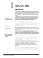
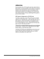
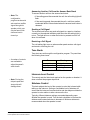
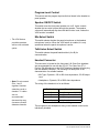
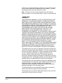
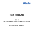
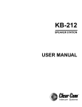
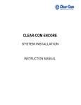
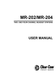
CLEAR-COM ECLIPSE
ICS-22
SPEAKER PANEL
INSTRUCTION MANUAL
ICS-22 Speaker Panel Instruction Manual
© 2000, 2008 Vitec Group Communications Ltd. All Rights Reserved.
Part Number 810264Z Rev. 2
Vitec Group Communications LLC
850 Marina Village Parkway
Alameda, CA 94501
U.S.A
Vitec Group Communications Ltd
7400 Beach Drive
IQ Cambridge
Cambridgeshire
United Kingdom
CB25 9TP
Vitec Group Communications
Room 1806, Hua Bin Building
No. 8 Yong An Dong Li
Jian Guo Men Wai Ave
Chao Yang District
Beijing, P.R. China 100022
® Clear-Com, CellCom/FreeSpeak and the Clear-Com Communications Systems logo are registered trademarks of
The Vitec Group plc.
CONTENTS
OPERATION . . . . . . . . . . . . . . . . . . . . . . . . . . . . . . 1-1
Description . . . . . . . . . . . . . . . . . . . . . . . . . . . . . . . . . . . . . . . . . . . . 1-1
Operation . . . . . . . . . . . . . . . . . . . . . . . . . . . . . . . . . . . . . . . . . . . . . 1-2
ECS System Configuration for ICS-22 Panels . . . . . . . . . . . . . . . 1-2
Front Panel . . . . . . . . . . . . . . . . . . . . . . . . . . . . . . . . . . . . . . . . . . 1-3
Talk Button and Light. . . . . . . . . . . . . . . . . . . . . . . . . . . . . . . . . 1-3
Answer-Back Facility . . . . . . . . . . . . . . . . . . . . . . . . . . . . . . . . . 1-4
Call-Waiting Light . . . . . . . . . . . . . . . . . . . . . . . . . . . . . . . . . . 1-4
Answer-Back Button. . . . . . . . . . . . . . . . . . . . . . . . . . . . . . . . 1-4
Answer-Back Stack . . . . . . . . . . . . . . . . . . . . . . . . . . . . . . . . 1-4
Answering a Call from the Answer-Back Stack . . . . . . . . . . . 1-4
Terminating Calls Answered with the Answer-Back Button . . 1-4
Answering Another Call from the Answer-Back Stack . . . . . . 1-5
Sending a Call Signal. . . . . . . . . . . . . . . . . . . . . . . . . . . . . . . 1-5
Receiving a Call Signal . . . . . . . . . . . . . . . . . . . . . . . . . . . . . 1-5
Tone Alerts . . . . . . . . . . . . . . . . . . . . . . . . . . . . . . . . . . . . . . . . 1-5
Intercom-Level Control . . . . . . . . . . . . . . . . . . . . . . . . . . . . . . . 1-5
Sidetone Control . . . . . . . . . . . . . . . . . . . . . . . . . . . . . . . . . . . . 1-5
Program-Level Control. . . . . . . . . . . . . . . . . . . . . . . . . . . . . . . . 1-6
Speaker ON/OFF Switch . . . . . . . . . . . . . . . . . . . . . . . . . . . . . . 1-6
Mic-Select Switch . . . . . . . . . . . . . . . . . . . . . . . . . . . . . . . . . . . 1-6
Talk/Listen Select Switch. . . . . . . . . . . . . . . . . . . . . . . . . . . . . . 1-6
Headset Connector . . . . . . . . . . . . . . . . . . . . . . . . . . . . . . . . . . 1-6
Panel-Mic Connector . . . . . . . . . . . . . . . . . . . . . . . . . . . . . . . . . 1-7
VOX Control. . . . . . . . . . . . . . . . . . . . . . . . . . . . . . . . . . . . . . . . 1-7
Internal Connections . . . . . . . . . . . . . . . . . . . . . . . . . . . . . . . . . . . 1-7
Call-Alert Tone-Level Control (1) . . . . . . . . . . . . . . . . . . . . . . . . 1-8
Option Switches (2) . . . . . . . . . . . . . . . . . . . . . . . . . . . . . . . . . . 1-8
Matrix Connector (3) . . . . . . . . . . . . . . . . . . . . . . . . . . . . . . . . . 1-8
Program-Input Connector (4). . . . . . . . . . . . . . . . . . . . . . . . . . . 1-8
Power Connection (5) . . . . . . . . . . . . . . . . . . . . . . . . . . . . . . . . 1-9
16-VAC Doorbell Transformer . . . . . . . . . . . . . . . . . . . . . . . . 1-9
14-VAC Wall-Mounted Power Supply . . . . . . . . . . . . . . . . . . 1-9
24- to 28-VDC Source . . . . . . . . . . . . . . . . . . . . . . . . . . . . . . 1-9
Vitec Group Communications
ICS-22 Speaker Panel Instruction Manual
i
QUICK START . . . . . . . . . . . . . . . . . . . . . . . . . . . . . 2-1
INSTALLATION . . . . . . . . . . . . . . . . . . . . . . . . . . . . 3-1
MAINTENANCE. . . . . . . . . . . . . . . . . . . . . . . . . . . . 4-1
Troubleshooting tips . . . . . . . . . . . . . . . . . . . . . . . . . . . . . . . . . . . . . 4-1
Technical Reference . . . . . . . . . . . . . . . . . . . . . . . . . . . . . . . . . . . . . 4-3
Bills of Materials . . . . . . . . . . . . . . . . . . . . . . . . . . . . . . . . . . . . . . 4-6
ICS-22 Main PCB (Part No. 710470). . . . . . . . . . . . . . . . . . . . . 4-6
ICS-22 VOX PCB (Part No. 710472) . . . . . . . . . . . . . . . . . . . . 4-11
Matrix Option PCB (Part No. 710533) . . . . . . . . . . . . . . . . . . . 4-15
SPECIFICATIONS . . . . . . . . . . . . . . . . . . . . . . . . . . 5-1
LIMITED WARRANTY . . . . . . . . . . . . . . . . . . . . . . . W-I
Warranty Period . . . . . . . . . . . . . . . . . . . . . . . . . . . . . . . . . . . . . . . . W-i
Technical Support . . . . . . . . . . . . . . . . . . . . . . . . . . . . . . . . . . . . . . . W-i
Warranty Repairs and Returns . . . . . . . . . . . . . . . . . . . . . . . . . . . . W-ii
Non-Warranty Repairs and Returns . . . . . . . . . . . . . . . . . . . . . . . . W-ii
Extended Warranty . . . . . . . . . . . . . . . . . . . . . . . . . . . . . . . . . . . . . W-ii
Liability . . . . . . . . . . . . . . . . . . . . . . . . . . . . . . . . . . . . . . . . . . . . . . W-iii
ii
Vitec Group Communications
ICS-22 Speaker Panel Instruction Manual
IMPORTANT SAFETY
INSTRUCTIONS
For your safety, it is important to read and follow these
instructions before operating a ICS-22 speaker panel:
(1) WARNING: To reduce the risk of fire or electric shock, do not
expose a ICS-22 speaker panel to rain or moisture. Do not operate a
ICS-22 speaker panel near water, or place objects containing liquid on
it. Do not expose a ICS-22 speaker panel to splashing or dripping
water.
Please read and follow
these instructions
before operating a
ICS-22 speaker panel.
(2) For proper ventilation, make sure ventilation openings are not
blocked. Install the ICS-22 speaker panel according to the directions in
the Installation chapter of this manual.
(3) Do not install a ICS-22 speaker panel near a heat source such as a
radiator, heat register, stove, or other apparatus (including amplifiers)
that produces heat. Do not place naked flame sources such as candles
on or near a ICS-22 speaker panel.
(4) Only use attachments/accessories specified by Clear-Com
Intercom Systems.
(5) Unplug the ICS-22 speaker panel during lightning storms or when
unused for long periods of time.
(6) Refer all servicing to qualified service personnel. Servicing is
required when:
• The ICS-22 speaker panel has been damaged in any way.
• Liquid has been spilled or objects have fallen into the ICS-22
speaker panel chassis.
• The ICS-22 speaker panel has been exposed to rain or moisture.
• The ICS-22 speaker panel does not operate normally.
• The ICS-22 speaker panel has been dropped.
Please familiarize yourself with the safety symbols in Figure 1. When
you see these symbols on a ICS-22 speaker panel, they warn you of
the potential danger of electric shock if the ICS-22 speaker panel is
used improperly. They also refer you to important operating and
maintenance instructions in the manual.
Vitec Group Communications
ICS-22 Speaker Panel Instruction Manual
iii
CAUTION
RISK OF ELECTRIC SHOCK
DO NOT OPEN
This symbol alerts you to the presence of uninsulated dangerous
voltage within the product's enclosure that might be of sufficient
magnitude to constitute a risk of electric shock. Do not open
the product's case.
This symbol informs you that important operating and maintenance instructions are included in the literature accompanying
this product.
Figure 1: Safety Symbols
iv
Vitec Group Communications
ICS-22 Speaker Panel Instruction Manual
1
OPERATION
DESCRIPTION
The Clear-Com ICS-22 is a two-channel speaker panel designed for
use in theatres, live performances, industrial environments, and small
television facilities. It features excellent speech intelligibility, even in
high noise levels, and can be customized through its programmable
options.
• The ICS-22 is a
two-channel speaker
panel.
• The panel must be
powered locally.
In addition, the ICS-22 contains a jack for an optional Clear-Com
gooseneck panel microphone and a close-in, voice-operated circuit
(VOX). This circuit allows automatic, alternate dipping of the panel
microphone and the speaker in response to conversation.
Selectable talking and/or listening allows the operator to communicate
on two talk/listen paths. The dual-action talk button operates in
electronic momentary or latching mode. Monitoring can be done
through the headset, the integral speaker, or both simultaneously. The
ICS-22 offers both visible and audible call signaling to attract the
attention of operators.
A balanced program input allows the monitoring of external audio
using the headset or speaker. This program input can also be used as
a paging function.
The ICS-22 speaker panel accepts dynamic headsets, such as the
Clear-Com PL-Pro™ Series HS-6 Telephone Handset, or PT-4
Push-to-Talk Hand Microphone. A sidetone control allows the operator
to vary the level of his voice heard through the headset and speaker.
• Users can install the
panel in Clear-Com’s
DT-Box.
The integral speaker can be turned on or off by a convenient
front-panel switch. An automatic speaker dipping circuit will lower the
level of the speaker whenever the talk button is activated. The
ICS-22’s close-in VOX dips the speaker or gooseneck microphone
automatically as the panel is used. These features help minimize
acoustical feedback.
The ICS-22 will need to be powered locally. In permanent wall
installations, a 16-VAC doorbell transformer will provide a convenient
source of power. In DT-Box installations, a 14- to 18-VAC
wall-mounted transformer will suffice. The connections to this
transformer are made to the circuit board’s two-terminal, plug-on
connector.
The unit mounts either in a standard USA four-gang electrical outlet
box or in an optional Clear-Com DT-Box. The extra thick front panel
and compact, surface-mounted circuitry results in a reduced size and
lighter weight package that maintains Clear-Com ruggedness.
Vitec Group Communications
ICS-22 Speaker Panel Instruction Manual
1-1
OPERATION
Normal operation of the ICS-22 speaker panel only requires the front
panel controls. For intercom operation, set the intercom level control to
the desired level and press the talk button when talking. If a headset or
handset is used, set the sidetone control for each channel for the
desired amount of sidetone in the earphone. If the PT-4 hand-held,
push-to-talk microphone is used, or if the panel microphone is used,
set the sidetone controls for minimum feed-through to the speaker to
prevent acoustic feedback.
ECS System Configuration for ICS-22 Panels
The Eclipse Configuration System (ECS) software does not directly
support the ICS-22 speaker panel. In order to configure an ICS-22
panel the port is configured to drive an ICS-1008 panel with 14 keys (7
pairs of buttons). The two ICS-22 selectors are mapped onto the
ICS-1008 keys starting from the left. Only the leftmost two pairs of
keys on the ICS-1008 can be used to program the ICS-22; any other
keys on the ICS-1008 will have no effect.
There must be a corresponding listen key on the top row to the talk key
on the bottom row of the ICS-1008 configuration for the ICS-22 panel
to work correctly. If a talk key only is configured on the ICS-1008 in
ECS the Talk key on the ICS-22 will not latch.
It should be noted that the panel signalling and control protocol used
by the Eclipse matrix differs from the Matrix Plus 3. As a result the
operation of these panels with an Eclipse matrix may be slightly
different to their operation with a Matrix Plus 3.
1-2
Vitec Group Communications
ICS-22 Speaker Panel Instruction Manual
FRONT PANEL
• Appropriately setting
the sidetone level
decreases confusion,
especially in loud
environments.
The controls, indicators, and connectors on the ICS-22 front panels are
shown below and are described in the text that follows.
A
VOX
Call Waiting
B
Talk/Listen Select
Panel Mic
Answer Back
Intercom Level
Headset
Program Level
Off
Sidetone
Talk
On
Speaker
Figure 1-1: ICS-22 Front Panel
Talk Button and Light
• The talk button has
five functions.
This button transmits the headset or gooseneck microphone audio to
the selected talk/listen panel/interface or the answer-back label. The
talk button has a dual action (momentary or latching) depending upon
how the button is pressed. The Talk button Latch/Non-Latching
operation cannot be defeated in ECS even for latch disabled labels.
The following describes the various functions of this button:
• Momentary—Press and hold the talk button while speaking.
Release it when finished. The light will be illuminated when the
button is pressed.
• Latching—Press and release the button quickly to latch the talk
function. Press and release the button again to turn off the talk
function. The light will be illuminated while the button is latched.
• Talk indication—The associated talk light will illuminate green
when the talk function is activated.
• VOX indication—When the VOX feature is enabled, the talk light
will illuminate green when the talk function is activated, but will
turn red when the panel microphone is in use. This automatically
dips the speaker volume.
• Speaker dip—If the front-panel speaker is turned on and the VOX
feature is not used, pressing the talk button will reduce the
speaker output level to avoid feedback.
Vitec Group Communications
ICS-22 Speaker Panel Instruction Manual
1-3
• Note: The
call-waiting light does
not light when a call
is received from a
programmed label.
Answer-Back Facility
The answer-back facility answers calls from panels or interfaces that
the panel has not currently selected.
Call-Waiting Light
This dual-function light:
• is steadily lit when a call signal is received
• flashes to indicate a call waiting signal, which has priority over a
call signal.
Answer-Back Button
This three-function button:
• sends a call signal to the selected, programmed label when the
call waiting light is off
• directs audio to the longest-waiting call in the call-waiting stack
when the call waiting light is flashing
• The panel’s
answer-back feature
offers a number of
functions.
• ends the current conversation from the call-waiting stack when
the call waiting light is steadily on.
Answer-Back Stack
The answer-back stack tracks incoming calls from any label that is not
assigned to the panel. These calls are available in the order they were
received. The length of time the calls are available before they are
automatically removed is set in the configuration program.
Note: The label programmed to and selected by the panel will
never appear in the answer-back stack and duplicate labels
are never added.
Answering a Call from the Answer-Back Stack
To answer a call from the answer-back stack:
1. Press and release the answer-back button to select the longest
waiting call.
2. Press the answer-back button while responding. The call waiting
light will be on steadily.
• A tone alert is
provided to ensure
call signals are
noticed.
Terminating Calls Answered with the Answer-Back Button
To terminate a call answered with the answer-back button, turn off the
call waiting light, and recover the previous call:
• The receiving panel can terminate the call by pressing and
releasing the answer-back button.
• The calling panel can terminate the call.
1-4
Vitec Group Communications
ICS-22 Speaker Panel Instruction Manual
Answering Another Call from the Answer-Back Stack
To answer another call from the answer-back stack:
• Note: The
configuration
program can be set to
also send an audible
signal through the
speaker, which can
only be heard if the
intercom level is
turned up.
• If the calling panel disconnected the call, the call waiting light will
flash.
• If the receiving panel disconnected the call, a call from another
unselected label will be activated when the answer-back button is
released.
Sending a Call Signal
The answer-back button can send call signals to a panel or interface
currently on the selected talk/listen path when the call-waiting light is
not on. The light will turn on when the button is pressed and turn off
when it is released.
Receiving a Call Signal
The call waiting light turns on when another panel sends a call signal
and remains on during the call.
Tone Alerts
Tone alerts are set through the configuration program. The panel has
the following three tones:
• A number of controls
are available to
adjust the panel’s
audio levels.
Tone
Meaning
Four rapid beeps Call signal
Two beeps
Label change
Single beep
Monitoring
Table 1-1: ICS-22 Tone Alerts
Intercom-Level Control
• Note: Forcing the
trimpots past their
stop points will
damage them.
This control sets the listen level required on the speaker or headset. It
does not affect the program-input level.
Sidetone Control
This knob adjusts the level of the operator’s voice that is heard while
talking on the intercom. Setting a comfortable level of sidetone will
ensure that the intercom line sounds alive and also helps modulate the
operator’s voice relative to other voices on the line.
Typically, different sidetone settings are needed depending upon
whether the speaker is used. Turn the knob clockwise to increase the
sidetone and counterclockwise to decrease it. Minimum sidetone is
recommended when the speaker is used.
Vitec Group Communications
ICS-22 Speaker Panel Instruction Manual
1-5
Program-Level Control
This control sets the program input audio level heard in the headset or
panel speaker.
Speaker ON/OFF Switch
This switch turns the front-panel speaker on or off. It also controls
whether the tone alert is heard through the speaker. The speaker
volume will automatically dip when the talk function is set, unless the
VOX function is enabled.
Mic-Select Switch
• The VOX feature
provides operators
with a voice activated
option.
This switch selects whether the panel microphone or the headset
microphone is active. When the VOX feature is enabled, it is only
operational when the panel microphone is active.
Talk/Listen Select Switch
This switch selects the panel/interface label (A or B) for
communication.
Headset Connector
This connector is located on the front panel. All Clear-Com headsets
are recommended for use with the ICS-22. The Clear-Com PT-4
Push-to-Talk Microphone or the HS-6 Telephone Handset will also plug
into the headset connector. The following is a description of the
characteristics of a suitable headset:
• Mic Type—Dynamic; 150 to 400 ohms impedance; -55 dB output
level.
• Note: Do not connect
Pins 1 and 3
together. Headset
extension cords or
headset “Y” cables
are not
recommended
because they may
increase crosstalk
between channels.
1-6
• Headphone—Dynamic; 50 to 2000 ohms impedance.
The wiring of the headset is to be as follows:
Pin Number
Description
1
2
3
4
Microphone ground (shield)
Microphone hot
Headphone ground
Headphone hot
Table 1-2: ICS-22 Headset Wiring
The microphone and headphone wiring in the headset cord must be
individually shielded.
Vitec Group Communications
ICS-22 Speaker Panel Instruction Manual
Panel-Mic Connector
• To install a GM-9 or
GM-18 microphone
there are four steps.
Clear-Com recommends that the GM-9 (9-in. long) and GM-18 (18-in.
long) plug-in panel microphones be used with the ICS-22. Both are the
electret type. The 1/4-in. phone jack on the microphone mates with the
panel-mic receptacle on the ICS-22’s front panel.
To install a GM-9 or GM-18 microphone:
1. Remove the plastic plug from the jack, if present.
2. If a set screw is present in the microphone-mounting flange, check
and unscrew it to make sure it is clear of the threads in the bushing.
3. Screw the microphone into the bushing and tighten.
4. Optional: Replace the set screw supplied with the gooseneck
microphone on top of the microphone-mounting flange and turn it
clockwise to lock the microphone in place.
VOX Control
• The VOX control is
located to the right of
the panel microphone
connector and is
recessed slightly into
the front panel.
When the panel microphone is selected on the ICS-22, the VOX
control should be adjusted for proper operation. This control is located
to the right of the panel microphone connector and is recessed slightly
into the front panel. Use a narrow, flat-bladed screwdriver such as a
“greenie” or “tweaker” for this adjustment. When the adjustment is
correctly set, the talk lamp will be red when speaking into the panel
microphone and will be green when hearing audio from the speaker.
Turning the control clockwise makes the ICS-22 more sensitive. The
VOX feature can be disabled by turning the VOX control fully
counterclockwise.
INTERNAL CONNECTIONS
These controls are not to be adjusted on this panel, but are set as
follows:
Vitec Group Communications
ICS-22 Speaker Panel Instruction Manual
1-7
POWER CONNECTION
4
5
PROGRAM INPUT
• There are five internal
connections.
3
MATRIX CONNECTOR
VIEW FROM TOP
OF ICS-22
321
• Option switches
should not be
changed from their
factory settings.
• Note: The ON
position of each
option switch is
toward the circuit
board and the OFF
position is toward the
front panel. The
default position of the
switches is the OFF
position.
FRONT PANEL
CALL ALERT TONE LEVEL CONTROL
1
2
OPTION SWITCHES
Figure 1-2: Internal Adjustments and Connections
Call-Alert Tone-Level Control (1)
This feature must be disabled by turning the control fully
counterclockwise.
Option Switches (2)
The three option switches are set to the OFF position by the factory
and should not be changed.
Matrix Connector (3)
This eight-wire modular jack (RJ-45) provides an audio and data
communications link to the Matrix system.
Program-Input Connector (4)
A three-terminal, plug-on connector provides the program input to the
panel. Program is fed to the headset and speaker. The level to the
speaker or headset is controlled by the program-level control. The
program-input connector accepts a balanced or unbalanced line-level
audio signal from -20 dBu to +10 dBu. If this input is connected to the
stage announce (SA) output of a main panel it can be used as a paging
input. Since the level of this input is independently adjustable from the
intercom audio volume, it can be used to override the intercom audio.
1-8
Vitec Group Communications
ICS-22 Speaker Panel Instruction Manual
The pinout of this connector is as follows:
• The Program Input
can be set between
-20 dBu to +10 dBu.
Pin Number
Function
1
Ground (Shield)
2
Positive Signal
3
Negative Signal
Table 1-3: ICS-22 XLR Pinout Information
PIN 1
2
3
1
ICS-22 PROGRAM
INPUT CONNECTOR
XLR CONNECTOR
Figure 1-3: ICS-22 Program-Input Cable Wiring
• The panel can obtain
power from three
different sources.
Power Connection (5)
The panel requires local power, which can come from various sources,
including:
16-VAC Doorbell Transformer
• Note: Both 10-VAC
and 16-VAC doorbell
transformers are
commonly available
at hardware stores,
but only the 16-VAC
transformers are
suitable in this
case.The panel can
obtain power from
three different
sources.
A doorbell transformer can be attached to a separate box containing
the power-line connection and the low-voltage, 16-VAC can be routed
to the connector on the EB7-4W circuit board. This connection is
especially useful if the headset or speaker panel is installed in a wall.
14-VAC Wall-Mounted Power Supply
A Clear-Com wall-mounted power supply (part number 400008) can
be used for powering the panel from 120 VAC. (Use part number
400011 for 220 VAC power.) This connection is a better choice if the
headset or speaker is mounted in a desktop box, such as a Clear-Com
DT-Box, which is not located on a wall.
24- to 28-VDC Source
The headset or speaker panel can be powered from a DC source, such
as batteries.
To connect the selected power supply:
1. Connect the two wires from the power source to the two-position,
plug-on terminal strip.
2. Plug this connector onto the circuit board as shown in Figure 1-2 on
page 1-8.
Vitec Group Communications
ICS-22 Speaker Panel Instruction Manual
1-9
1-10
Vitec Group Communications
ICS-22 Speaker Panel Instruction Manual
2
• Users can use the
“Quick Start”
approach to get their
panels up and
running in minutes.
QUICK START
1. Unpack the unit and inspect it for any damage that may have
occurred during shipping.
2. Set the option switches to the default (up) position.
3. Connect the RJ-45 connector to the Matrix frame.
4. Connect 14- to18-VAC power to the two-terminal, plug-on
connector.
5. Install the ICS-22 into the USA standard four-gang outlet box.
6. Set listen levels and sidetones (see Figure 1-2 on page 1-8).
7. The speaker panel should now be operating properly.
8. Read the rest of this manual for further information.
• Note: When the
panel is initially
powered, the
call-waiting lamp will
blink slowly indicating
the panel is
attempting to
communicate with the
Matrix frame. Once
communication is
established, the
blinking will stop.
Vitec Group Communications
ICS-22 Speaker Panel Instruction Manual
2-1
2-2
Vitec Group Communications
ICS-22 Speaker Panel Instruction Manual
3
• The ICS-22 runs on
14- to 18-VAC power.
• Note: If the panel is
installed in a DT-Box,
the back cover of the
DT-Box must first be
removed. It is
retained with four
screws. Feed the
power cable through
one slot and fasten it
to the strain relief as
shown in Figure 1-2.
INSTALLATION
1. Connect the 14- to 18-VAC power to the two-position terminal strip.
Plug the terminal strip onto the P2 as shown in Figure 1-2 on page
1-6.
2. Connect the eight-wire, modular RJ-45 connector to J1 as shown in
Figure 1-2 on page 1-6.
3. If the RJ-45 Matrix connector should need to be unplugged, use the
following procedure:
1. Remove power from the panel.
2. If the panel is installed in a DT-Box, remove the front panel. It is
retained with four screws.
3. Using long-nosed pliers, grasp the top and bottom of the plug so
that the retaining clip will be depressed. Pull the plug out with the
pliers.
• Removing the RJ-45
Matrix connector
requires three steps.
• Note: If the panel is
installed in a DT-Box,
the back cover of the
DT-Box must first be
removed. Feed the
Matrix cable through
one slot and fasten it
to the strain relief as
shown in Figure 3-1
at right.
Vitec Group Communications
ICS-22 Speaker Panel Instruction Manual
Figure 3-1: ICS-22 DT-Box Wiring
3-1
3-2
Vitec Group Communications
ICS-22 Speaker Panel Instruction Manual
4
MAINTENANCE
TROUBLESHOOTING TIPS
Listed below are some of the more common problems the panel may
experience, their possible causes, and suggested solutions.
Symptom
System does not
operate and the talk
light does not turn on
when talk button is
pressed.
• Sometimes when the
talk light doesn’t work
it’s because the panel
isn’t receiving power.
• When the system
doesn’t operate,
make sure there isn’t
an incompatibility
problem.
Vitec Group Communications
ICS-22 Speaker Panel Instruction Manual
System does not
operate and the call
waiting light blinks
slowly.
Cause
1. The panel is not
receiving 14- to
16-VAC power.
Solution
1. Check the circuit
powering the panel
and make sure all plug
connections are
secure.
2. The panel has an
has an internal failure. 2. The panel requires
servicing.
Communication with Make sure each
the system is lost.
eight-wire, modular
connector is securely
plugged in, check the
wiring, and ensure that
the Matrix system is
turned on.
An incompatibility
Contact the dealer or
problem with the
Clear-Com’s technical
Matrix system.
service.
System does not
operate and the call
waiting light blinks
quickly.
Speaker does not
1. The speaker knob is
operate, but the talk
turned all the way
light comes on when down.
talk button is pressed.
2. The speaker plug or
wiring has come loose.
Hum or buzz in
Inductive pickup
system.
caused by close
proximity of this
speaker panel or
connected panels to
power lines or
transformers.
1. Adjust control
appropriately.
2. Make sure speaker
is connected internally.
Relocate the offending
unit or wiring.
4-1
Symptom
System feedback
(acoustical).
Solution
1. The intercom-level 1. Adjust.
control at this panel or
another panel is set
too high.
2. The sidetone control 2. Adjust (see Figure
at the panel or another 1-1 on page 1-2).
panel is incorrectly
adjusted.
• System feedback can
have three different
causes.
VOX problems.
• VOX problems can
be caused by
incorrect sensitivity
settings.
• Note: VOX is
intended for close-in
operation.
Cause
The program signal
sounds distorted.
Rapid clicking noise.
3. A headset extension 3. Remove the
cord was used.
extension cord
because its use is not
recommended.
1. VOX stays tripped 1. Turn the VOX
(red light on); the
sensitivity control
sensitivity is set too
counterclockwise.
high.
2. VOX will not trip
when speaking (green
light on); the sensitivity
is set too low.
1. The program-level
control is set too high.
2. Turn the VOX
sensitivity control
clockwise.
2. The program-input
circuit is overloaded.
2. Reduce the gain of
the program signal at
the source, such as an
audio mixer.
1. Repair/replace
wiring or connectors.
1. Defective wiring or
connectors.
2. Defective IC1 on
710533 assembly.
4-2
1. Turn the
program-level control
counterclockwise.
2. Replace IC1.
Vitec Group Communications
ICS-22 Speaker Panel Instruction Manual
Vitec Group Communications
ICS-22 Speaker Panel Instruction Manual
Talk
Mic Select
Matrix
Interface
16 VAC
Talk/Listen
Select Switch
Panel
Mic
Headset
Mic
Rectifier
B
A
VOX
Power
Microprocessor
RMK
Red /
Green
Talk/
VOX
Microprocessor
Mic Dip /
Mute
EQ/
LIM
Sidetone
Null
Call Send &
Receive
Answer
Back
Speaker
Dip
Call
Waiting
Light
Program
Level
Intercom
Volume
Program
Mute
Speaker
On/Off
Matrix
Connector
Balanced
Program
Input
Headset
Output
Speaker
TECHNICAL REFERENCE
Figure 4-1: ICS-22 Block Diagram
4-3
BLANK PAGE
4-4
Vitec Group Communications
ICS-22 Speaker Panel Instruction Manual
C28
R16
Q1
R13
R17
C7
C14
C47
Q3
R18
R22
C31
R26
R36
C35
R39
CALL ALERT TONE LEVEL
C32
IC9
R10 R9
C34
C18
C10
C11
R24
R11
P9
IC2
S3
R44
IC11
D14
C24
R28 C42
R53 1
IC10
D15
C19 R30
R6
C26
D5
1
S5
R27
C25
R46
C43
R15
R8
D8
J3
S4
C17
R54
C27
C39
R43
D11
Q5
IC8
P6
R1
IC5
R41
J1
R48
S2
R50
D7
C12 C21
Q4
D13
R29
R40
S1
C33
C36
COPYRIGHT (C) 1999
R33
R42
C8
D12
R7
D9
D10
D2
D16
P1
P2
P3
R4
Q2
D3
C5
R3
D6
ASSY #710470
C4
D4
R12
J2
W1
C41
R35
R49
C20
C30
R37
C40
C37
C23
C45
R34
R47
R2
D1
P7
W2
W3
R23
R51
C44
R32
C38
C29
R38
R31
CLEAR-COM
C16
R14
IC1
W4
R20
C6 C9
P5
R52 C13
4-5
Vitec Group Communications
ICS-22 Speaker Panel Instruction Manual
R21
R25
R45
C22
R19
C2
C15
C46
C1
Figure 4-2: Main PCB Component Layout (part no. 710470)
BILLS OF MATERIALS
ICS-22 Main PCB (Part No. 710470)
CAPACITORS
Designator
Description
C8 C47
C1
C28
C6
C11
C24
C17 C41
C14
C5 C19 C27 C30
C26
C7 C46
C16
220 uF Aluminum 35V
.01 uF Ceramic Disc 1.4KV 20%
22 uF Tantalum 16V
4.7 uF Tantalum 35V
4.7 uF Aluminum NP 50V
.047 uF Mylar 100V 5%
100 uF Aluminum 35V
22 pF Ceramic SMD 50V 5%
47 pF Ceramic SMD 50V 5%
220 pF Ceramic SMD 50V 5%
470 pF Ceramic SMD 50V 5%
.0022 uF Ceramic SMD 50V
10%
C9 C20 C22
.0047 uF Ceramic SMD 50V
10%
C13 C37 C38 C40 C31 C29 .01 uF Ceramic SMD 50V 10%
C18 C35
.047 uF Ceramic SMD 50V 10%
C10 C25 C32 C33 C34 C36 .1 uF Ceramic SMD 50V 10%
C45
C15 C21 C23
.22 uF Ceramic SMD 50V 10%
C44 C39
.47 uF Tantalum SMD 35V 10%
C2 C4 C12 C43
1 uF Tantalum SMD 16V 10%
C42
10 uF Tantalum SMD 25V 10%
Qty
2
1
1
1
1
1
2
1
4
1
2
1
3
6
2
7
3
2
4
1
RESISTORS
Designator
R15 R53
R46
R44
R27
R25
R45 R35
R13
4-6
Description
10 OHM 1/4 Carbon Film 5%
390 OHM 1/4 Carbon Film 5%
1.3K OHM 1/2 Carbon Film 5%
2.2 OHM 1/10 SMD 5%
39.2 OHM 1/10 SMD 1%
100 OHM 1/10 SMD 1%
221 OHM 1/10 SMD 1%
QTy
2
1
1
1
1
2
1
Vitec Group Communications
ICS-22 Speaker Panel Instruction Manual
Designator
R47 R51
R20
R22
R14 R33
R43
R18 R21 R42
R48
R28
R17
R52
R19 R38
R16
R24 R30 R31 R34 R39
R37 R41
R6 R12 R49 R50
R32
R26
R54
R8 R9 R10 R11
R2 R3
R1
R7
R4
R36
R40 R23
R29
Description
301 OHM 1/10 SMD 1%
432 OHM 1/10 SMD 1%
825 OHM 1/10 SMD 1%
1.00K OHM 1/10 SMD 1%
1.50K OHM 1/10 SMD 1%
2.00K OHM 1/10 SMD 1%
2.74K OHM 1/10 SMD 1%
6.19K OHM 1/10 SMD 1%
6.81K OHM 1/10 SMD 1%
8.25K OHM 1/10 SMD 1%
12.1K OHM 1/10 SMD 1%
15.0K OHM 1/10 SMD 1%
20.0K OHM 1/10 SMD 1%
56.2K OHM 1/10 SMD 1%
100K OHM 1/10 SMD 1%
121K OHM 1/10 SMD 1%
475K OHM 1/10 SMD 1%
1.0M OHM 1/10 SMD 5%
10K OHM X4 SMD DIP Isolated
1%
47K OHM X4 SMD DIP Isolated
1%
100K OHM X4 SMD DIP
Isolated 1%
220K OHM X4 SMD DIP
Isolated 1%
470K OHM X4 SMD DIP
Isolated 1%
Pot 10K TRIMPOT
Pot 5K TRIMPOT
Pot 5K POT
QTy
2
1
1
2
1
3
1
1
1
1
2
1
5
2
4
1
1
1
4
2
1
1
1
1
2
1
DIODES AND TRANSISTORS
DESIGNATOR
D8
D14
IC5
IC11
D9 D12 D15 D16
IC1 IC2 IC8
Vitec Group Communications
ICS-22 Speaker Panel Instruction Manual
DESCRIPTION
LED BI-COLOR RED/GREEN
LED LED, YLW, ULTRA BRGHT
IC LM384 POWER 4W OP AMP
IC 7805L POS 5V REGLTR
Diode BAV70 DUAL DIODE
IC 833 DUAL OP AMP
QTY
1
1
1
1
4
3
4-7
DESIGNATOR
Q2
D1 D2 D3 D4 D5 D6 D11
D13
Q5
IC9
Q1 Q3
D7 D10
Q4
C10
DESCRIPTION
Transistor 2907A PNP 60V
600MA
Diode BAV99 DUAL DIODE
Transistor MPSA14 DNPN 30V
300MA
IC DG444 QUAD CMOS
ANALOG SW
Transistor J175 P-CHANNEL
JFET
Diode 5.1V 5% ZENER 1/4W
Transistor MPSA64 DPNP 30V
500MA
IC MICROPROCESSOR,
KB/MR SERIES
QTY
1
8
1
1
2
2
1
1
MISCELLANEOUS
Designator
P4
P10
R29
S5
S4
D14
S4 S5
S2
S3
S1
4-8
Description
Connector 5 POS, SCREW
TERM
XLR 4 PIN M FLSH MNT
Connector 3 POS, SCREW
TERM.
Pot KNOB GRY INSRT .45 DIA
PT TO RD
Button RND MINIATURE
BUTTON, BLCK
Button RECT. MINIATURE
BUTTON, BLCK
Lens LENS, YELLOW, ROUND
Speaker 2 1/2 IN. SPKR 16
OHM 3.5W
Switch DPDT P.B.
Switch DPDT ROCKER PC
MNT W/BRCKT
Switch DIP SWITCH PIANO 3
POS
Switch SPDT ROCKER
Qty
1
1
1
1
1
1
1
1
2
1
1
1
Vitec Group Communications
ICS-22 Speaker Panel Instruction Manual
XLR 4
XLR 3
P7
1
2
P5
W4
JUMPER
W3
JUMPER
A
D5
BAV99
2
1
D6
BAV99
3
1
2
3
C46
470pF
JP1
1
2
4
+
R35
100*
C6
4.7uF
2
3
1
3
R4C
470K*
IC9A
6
2
1
2
1
2
1
7
4
13
2
DG444
R4B
470K*
C7
470pF
B
2
R17
6.8K*
+V3
C32
.1uF
8
R19
12.1K*
+
+V1
VDD
C4
1uF
Q2
MMBT2907A
1
R3A
47K*
1
1
1
+V1
R52
8.2K*
R51
300*
VOX
R3B
47K*
1
2
C10
.1uF
IC2A
LM833
Bias-1
4
5
C11
4.7uF
R21
2K*
C
R20
430*
3
C18
.047uF
R24
20K*
INTERCOM
LINE
C19
47pF
7
6
R7C
220K*
D
INTERCOM
CHANNEL(S)
R53
10
P4
R31
20K*
2
4
C47
220uF
+
C20
.0047uF
C21
.22uF
R8C
10K*
R15
10
6
6
1
3
5
7
+V2
8
7
2
8
6
1
3
1
3
1
8
1
5
5
3
8
+V2
E
C17
100uF
R27
2.2
C25
.1uF
2
5
C33
.1uF
8
2
VDD
VSS
3
3
8
7
1
8
7
3
1
1
6
7
6
1
2
4
G
6
1
2
2
4
4
GND
1
2
R1D
100K*
1
2
3
P6
R54
1M
CALL
LIGHT
D14
R44
1.3K 1/2 W
BALANCED
PROGRAM
INPUT
3
2
1
P8
SPEAKER
+V2
SPEAKER
ON-OFF
S1
R49
100K*
C36
.1uF
Bias-1
+
E
Q5
MMBTA14
R50
100K*
C44
.47uF
C40
.01uF
C45
.1uF
+ C8
220uF
IC5
LM384
7
R34
20K*
2
SIGNAL
CALL
R41
56.2K*
3
2
C30
47pF
IC8B
LM833
+V1
+
IC8A
LM833
D11
BAV99
3
1
2
1
R37
56.2K*
+
-
C27
47pF
R8B
10K*
+
-
+ C12
1uF
2
2
6
5
+V2
1
R40
5K POT
PROGRAM
VOLUME
CW
Bias-1
2
R42
2K*
13
12
11
10
5
4
3
7
1
5
5
R8A
10K*
15
R39
20K*
+V2
R43
1.5K*
+ C39
.47uF
D13
BAV99
Q4
MMBTA64
VDD
C43
1uF
D7
5.1V
Bias-1
+
14
8
R7D
220K*
DG444
R48
2.74K*
3
POWER
CH B
4
IC9C
S2
CHANNEL
SELECTOR
9
11
2
CW
4
R1A
100K*
VOut
1
+V2 +V2
DG444
R36
10K POT
2
10
AMPLIFIER
R29
5K POT
INTERCOM
VOLUME
2
D2
BAV99
3
IC9D
ALERT
TONE
VOLUME
14
VIn
IC11
7805L
R1B
100K*
16
C42
10uF
3
Bias-1
+V3
R46
390
+
R8D
10K*
S3A
510114
SINGLE
CHANNEL
CH A
CW
R33
1K*
Bias-1
1
+
D16
BAV70
R10D
10K*
R45
100*
C41
100uF
+V1
2
2
2
3
IC2B
LM833
P3
1
2
3
4
5
6
7
8
R9D
10K*
R38
12.1K*
C29
.01uF
4-WIRE
OPTION (1)
1
2
3
4
5
6
7
8
R6
100K*
+
J3
6
4
3
1
C35
.047uF
C31
.01uF
5
6
RECEIVER
2
5
S5
CALL
R7B
220K*
D12
BAV70
R1C
100K*
1
Bias-1
R30
20K*
Bias-1
D9
BAV70
3
1
6
R26
470K*
3
R9B
10K*
VDD
D10
5.1V
J1
1
1
1
1
C37
.01uF
R28
6.2K*
C26
220pF
R23
5K POT
2
SIDETONE
NULL
CW
R32
121K*
4
P1
R7A
220K*
5
4
3
2
1
R25
39*
C16
.0022uF
+V1
C22
.0047uF
7
R11D
10K*
R9A
10K*
5
CALL ON
BOTH
8
1
LONG LINE
S3B
4
2
Bias-1
C24
.047uF
IC9B
DG444
R11C
10K*
1
2
3
4
5
6
7
8
9
10
2
4-WIRE
OPTION (2)
3
SPARES:
4
7
1
R2D
47K*
3
8
5
6
D
3
+
-
+V1
C5
47pF
7
INTERCOM
LINE
R3D
47K*
3
2
DRIVER
5
6
8
R10C
10K*
C23
.22uF
R2C
47K*
R3C
47K*
8
8
10
9
8
7
6
5
IC10
PIC16C505
C15
.22uF
RC0
RC1
RC2
RC3
RC4
RC5
R47
300*
D8
TALK
CALL ON
SELECTED
1
2
3
4
5
6
7
8
9
10
TW POWER
OPTION
R4A
470K*
6
C9
.0047uF
3
RB0
RB1
RB2
RB3
RB4
RB5
VDD
Bias-1
C14
22pF
7
R9C
10K*
13
12
11
4
3
2
C34
.1uF
IC1B
LM833
6
VDD
2
3
+
1
+V1
5
6
PREAMP
R16
15K*
R18
2K*
+
-
R22
825*
2
3
IC1A
LM833
1
D15
BAV70
2
R13
220
Q1
MMBFJ175
3
3
Q3
MMBFJ175
+V1
R2B
47K*
12
3
C13
.01uF
D3
BAV99
Bias-1
D4
BAV99
3
R2A
47K*
P9
1
2
3
4
5
6
5
3
D1
BAV99
3
R12
100K
R4D
470K*
VDD
C2
1uF
R14
1K*
W1
JUMPER
P2
2
4
6
8
10
12
14
+
HEADSET
XLR 2
XLR 1
XLR G
C1
.01uF 1.4KV
+
+
+
+
+
+
+
J2
+
+
+
+
+
+
+
GM / VOX
OPTION
5
+
C28
22uF
VDD
R11A
10K*
R11B
10K*
4
C
+
4
W2
JUMPER
+V1
1
3
5
7
9
11
13
R10A
10K*
R10B
10K*
6
4
3
1
PROGRAMMING / TEST INTERFACE
1 - Gnd / Gnd
2 - Data / Strobe
3 - n/a / Data Out
4 - Clock / Clock
5 - MCLR (not) / Data In
6 - +5V / n/a
2
S4
5
TALK
S3C
C38
.01uF
3
LATCH
DISABLE
510114
1. ALL RESISTORS ARE 1/10W 5% LISTED IN OHMS
NOTES: (UNLESS OTHERWISE SPECIFIED)
B
2. ALL CAPACITORS ARE LISTED IN MICROFARADS
3. ALL DIODES ARE 1N4148
4
3
2
1
4-9
Vitec Group Communications
ICS-22 Speaker Panel Instruction Manual
3
2
1
A
Figure 4-3: ICS-22 Schematic (part no. 710470)
7
1
14
3
3
R
2
3
1
1
3
4
2
3
2
3
1
4
BLANK PAGE
4-10
Vitec Group Communications
ICS-22 Speaker Panel Instruction Manual
Figure 4-4: VOX PCB Component Layout (part no. 710472)
ICS-22 VOX PCB (Part No. 710472)
CAPACITORS
Designator
C13
C10
C8 C12
C1 C2 C3
C5
C4
C6 C9
C11
Vitec Group Communications
ICS-22 Speaker Panel Instruction Manual
Description
1 uF Aluminum NP 50V 10%
470 pF Ceramic Disc 50V 10%
4.7 uF Tantalum 16V
.1 uF Monolithic 50V 10%
680 pF Ceramic Disc 50V 10%
.022 uF Monolithic 50V 10%
.01 uF Monolithic 50V 20%
220 uF Aluminum 16V 20%
Qty
1
1
2
3
1
1
2
1
4-11
Designator
C14
Description
22 uF Tantalum 10V 10%
Qty
1
RESISTORS
Designator
R1 R12 R16 R17 R13
R2
R6
R4 R8
R11 R15
R14
R3 R10
R9
R5
Description
4.7K OHM 1/4 Carbon Film 5%
6.8K OHM 1/4 Carbon Film 5%
1.5K OHM 1/4 Carbon Film 5%
1M OHM 1/4 Carbon Film 5%
100K OHM 1/4 Metal Film 1%
20K OHM 1/4 Carbon Film 5%
10K OHM X5 SIP ISOLATED
100K OHM X4 SIP ISOLATED
Pot 50K TRIMPOT
Qty
5
1
1
2
2
1
2
1
1
DIODES AND TRANSISTORS
Designator
D3 D4 D5 D6 D7 D8
Q1 Q2
IC1 IC2
D1 D2
D9
Description
Diode 1N4148 SIGNAL 10MA
75PIV
Transistor PN2222A NPN 30V
IC LF353 BIFET OP AMP
Diode 1N5231B ZENER 5.1V
.5W 5%
Diode 1N4740A ZENER 10V
0.5W 5%
Qty
6
2
2
2
1
MISCELLANEOUS
Designator
R5
S1
4-12
Description
Panel Mic Jack PHONE JACK
Pot SHAFT FOR PIHER POT
BLACK
Switch DPDT TOGGLE
Qty
1
1
1
Vitec Group Communications
ICS-22 Speaker Panel Instruction Manual
Vitec Group Communications
ICS-22 Speaker Panel Instruction Manual
2
10
7
D9
1N4740A
10V
+V4
+V1
9
A
C11
220uF
R10D
10K X 5I
+V1
Bias
5
R10E
10K X 5I
R10C
10K X 5I
R3E
10K X 5I
+
6
Bias-2
4
9
1
IC1A
LF353
3. ALL DIODES ARE 1N4148
B
2. ALL CAPACITORS ARE LISTED IN MICROFARADS
+
R3D
10K X 5I
1N4148
D3
R11
100K*
C5
680pF
1. ALL RESISTORS ARE 1/10W 5% LISTED IN OHMS
NOTES: (UNLESS OTHERWISE SPECIFIED)
C14
22uF TANT
+
-
C1
.1uF
D1
1N5231B
5.1V
8
R14
20K
4
Bias-2
3
2
+V1
C3
.1uF
C12
4.7uF 16V
R13
4.7K
Bias-2
5
6
+
-
VOX
ANTI
7
C
D6
1N4148
IC1B
LF353
C6
.01uF
C4
.022uF MONO
D7
1N4148
D4
1N4148
D2
1N5231B
5.1V
D8
1N4148
6
R3C
10K X 5I
R15
100K*
5
+V4
5
R9D
100K X 4I
R9C
100K X 4I
7
8
6
C8
4.7uF 16V
R9A
100K X 4I
R4
1M
D
R9B
100K X 4I
R8
1M
R5
50K POT
CW 3
D
1
2
R12
4.7K
3
R10B
C10 10K X 5I
470pF
PANEL MIC
1
VOX
R3A
10K X 5I
R2
6.8K
C
3
1
+
1
C13
1uF NP
2
VDD
8
Bias
R10A
10K X 5I
HEADSET
1
2
3
S1
4
5
6
R17
4.7K
R1
4.7K
Q1
2N2222A
B
D5
1N4148
R6
1.5K
+V1
3
2
5
6
+
-
+
-
Bias-2
8
2
PANEL
MIC
+V1
13
11
9
7
5
3
1
1
2
3
P1
P2
Bias
VDD
+
+
+
+
+
+
+
1
3
4
A
+
+
+
+
+
+
+
2
+
14
12
10
8
6
4
2
C9
.01uF
7
IC2A
LF353
1
C2
.1uF
IC2B
LF353
R3B
10K X 5I
VDD
Q2
2N2222A
3
4
4
4
7
10
8
Figure 4-5: VOX Schematic (part no. 710472)
4-13
R16
4.7K
E
E
1
2
3
4
BLANK PAGE
4-14
Vitec Group Communications
ICS-22 Speaker Panel Instruction Manual
P3
R7
T2
R2
Z3
C6
R5
IC3
R8
C5
R6
C3
C2
T1
R1
C1
R10
C4
P2
Q1
R4
16-18
VAC
R3
PWR
R9
D1
IC2
D3
P4
IC1
ASSY #710533
J1
P1
CLEAR-COM
COPYRIGHT (C) 1999
Figure 4-6: Matrix Option PCB Component Layout (part no. 710533)
Matrix Option PCB (Part No. 710533)
CAPACITORS
Designator
C6
C5
C4
C3
C2
C1
Vitec Group Communications
ICS-22 Speaker Panel Instruction Manual
Description
10 uF Aluminum 50V
.022 uF Monolithic 50V 10%
.1 uF Monolithic 100V 10%
.0022 uF Monolithic 50V 10%
100 uF Aluminum 35V
2200 uF Aluminum 35V 20%
Qty
1
1
1
1
1
1
4-15
RESISTORS
Designator
R5
R6
R8
R9
R1 R7
R10
R2
R4
R3
Description
2K OHM 1/4 Carbon Film 5%
47K OHM 1/4 Carbon Film 5%
1.5K OHM 1/4 Carbon Film 5%
330 OHM 1/4 Carbon Film 5%
100 OHM 1/4 Carbon Film 5%
2.2M OHM 1/4 Carbon Film 5%
10K OHM X5 SIP ISOLATED
4.7K OHM X 4 SIP ISOLATED
100K OHM X4 SIP ISOLATED
Qty
1
1
1
1
2
1
1
1
1
DIODES AND TRANSISTORS
Designator
D3
Description
Diode 1N4148 SIGNAL 10MA
75PIV
Transistor TIP41 NPN 40V 6A
Diode 1.5A 200V BRIDGE
Q1
D1
Qty
1
1
1
INTEGRATED CIRCUITS
Designator
IC3
IC1
Description
IC LM833N
IC 488E RS-422 XCVR
Qty
1
1
MISCELLANEOUS
Designator
T2
T1
IC2
P2
4-16
Description
Transformer 600CT/600CT
Transformer 10K:10K
IC MICRO, KB/MR MATRIX
OPTION
Connector 2 POS HSING,
SCRW TRM.
Qty
1
1
1
1
Vitec Group Communications
ICS-22 Speaker Panel Instruction Manual
A
PROGRAMMING / TEST / INTERROGATION
R4A
4.7K
B
Q1
TIP41
P4
7
R3D
100K
1
10K
IC3A
LM833
R2C
5
VDD
+
13
12
11
4
3
2
Programming / Test / Vdd /
Interrogation Connection
R4D
4.7K
VDD
3
2
3
VDD
8
RB0
RB1
RB2
RB3
RB4
RB5
6
C
RC0
RC1
RC2
RC3
RC4
RC5
10
9
8
7
6
5
IC2
PIC16C505P
/Ch. A
P1
R2D
10K
Latch Disable
7
8
P3
R5
2K
D3
1N4148
R2E
10K
VDD
R10
2.2M
D
C4
.1uF
3
2
C3
.0022uF
C5
.022uF
1.5K
R6
47K
R8
7
VDD
-
7
8
6
IC1
MAX488E
+ 5
+
2
T1
MET-09
1
-
5
VDD
3
1
2
3
4
C6
10uF
T2
TTC108
5
6
4
6
R7
100
1
1 - Gnd /Gnd /Gnd
3 - n/a/Data Out /Data In
VDD
R3A
100K
/Ch. C
/Ch. D
2
R2B
10K
+
3
4
2 - Data/Strobe Out /Strobe In
4 - Clock/Clock Out/Clock In
VDD
R3B
100K
D1
+ 2
R1
100
R2A
10K
6
Sense Talk
5
IC3B
LM833
4
6 - +5V / +5V/ +5V
1
J2
J3
1
4 +
C1
2200uF 35V
+
1
2
3
4
5
6
7
8
Call Button
5 - MCLR (not)/Data In/Data Out
P2
1
2
C2
100uF
VDD
1
2
3
4
5
6
7
8
9
10
4-WIRE
OPTION
CONNECTORS
D
+
P5-6
P5-7
16-20
VAC
NOTES: (UNLESS OTHERWISE SPECIFIED)
2. ALL CAPACITORS ARE LISTED IN MICROFARADS
1. ALL RESISTORS ARE 1/4W 5% LISTED IN OHMS
C
9
10
1
VDD
14
7
B
8
VSS
Call Light
6
5
4
3
2
1
4
4
3
2
1
A
3
4
2
8
R4B
4.7K
E
R9
330
R4C
4.7K
5
J1
1
2
3
4
5
6
7
8
6
R3C
100K
MATRIX
CONNECTOR
SPARES:
E
4
3
2
1
4-17
Vitec Group Communications
ICS-22 Speaker Panel Instruction Manual
6
5
2
1
1
3
1
1
1
2
4
3
Figure 4-7: Matrix Option Schematic (part no. 710533)
BLANK PAGE
4-18
Vitec Group Communications
ICS-22 Speaker Panel Instruction Manual
5
SPECIFICATIONS
Note: 0 dBu is referenced to 0.775 V RMS
Headset Microphone Pre-Amp
Input Type
Impedance
Input Level
Dynamic
1k ohm
-55 dBu nominal; -10 dBu max.
Panel Microphone Pre-Amp (KB-211GM only)
Input Type
Input Level
Electret
-45 dBu nominal
Pre-Amp Response Curve
Frequency Response
intelligibility
Limiter Range
250 Hz to 12 kHz, contoured for
20 dB
Headphone Amplifier
Load Impedance Range
Output Level
Distortion
Frequency Response
Power Output
50 ohm to 2k ohm
at least +20 dBu across 600 ohm
< 0.5% THD at 1 kHz
200 Hz to 15 kHz, ±3 dB
110 dB SPL
Speaker Amplifier
Speaker Type
Power Output
Frequency Response
Signal-to-Noise
Distortion
Speaker Level
2.5 in. round, 16 ohm
2 W into 16 ohms
200 Hz to 15 kHz, ±3 dB
75 dB
< 0.5% THD at 1 kHz
98 dB SPL at 3 ft.
Program Amplifier
(Transformerless, balanced differential input)
Input Level
-20 dBu
Input Impedance
> 100k ohm
Frequency Response
150 Hz to 15 kHz, ± 3 dB
Power Requirements
Voltage
Current
30-VDC standard unit;
16- to 18-VAC with 4-Wire Option Module
100 mA average
Internal Connectors
Program
Vitec Group Communications
ICS-22 Speaker Panel Instruction Manual
Three-position, plug-on screw terminals
5-1
AC Power
Two-position, plug-on screw terminals
Front Panel Connectors
Panel Mic
Headset:
(1) 1/4-in. panel mounting jack
(1) XLR-4M
Front Panel Controls & Indicators
Panel/headset-mic switch
Program-level control
Intercom-volume control
Sidetone control
Talk button
Answer-back button
VOX control
Talk/listen selector
Speaker on-off switch
Talk light
Call-waiting light
(1)
(1)
(1)
(1)
(1)
(1)
(1)
(1)
(1)
(1)
(1)
Environmental
32° to 122° F (0° to 50° C)
Dimensions
8.25 in. W x 4.5 in. H x 1.75 in. D
(210 mm x 114 mm x 44 mm)
Weight
ICS-22
1.34 lb. (0.61 kg)
Notice About Specifications
While Clear-Com makes every attempt to maintain the accuracy of the
information contained in its product manuals, that information is
subject to change without notice. Performance specifications included
in this manual are design-center specifications and are included for
customer guidance and to facilitate system installation. Actual
operating performance may vary.
5-2
Vitec Group Communications
ICS-22 Speaker Panel Instruction Manual
LIMITED WARRANTY
Vitec Group Communications (VGC) warrants that at the time of
purchase, the equipment supplied complies with any specification in
the order confirmation when used under normal conditions, and is free
from defects in workmanship and materials during the warranty period.
During the warranty period VGC, or any service company authorized
by VGC, will in a commercially reasonable time remedy defects in
materials, design, and workmanship free of charge by repairing, or
should VGC in its discretion deem it necessary, replacing the product
in accordance with this limited warranty. In no event will VGC be
responsible for incidental, consequential, or special loss or damage,
however caused.
WARRANTY PERIOD
Return Material Authorization
(RMA) numbers are required
for all returns.
Both warranty and
non-warranty repairs are
available.
The product may consist of several parts, each covered by a different
warranty period. The warranty periods are:
• Cables, accessories, components, and consumable items have a
limited warranty of 90 days.
• Headsets, handsets, microphones, and spare parts have a limited
warranty of one year.
• UHF wireless IFB products have a limited warranty of one year.
• UHF wireless intercom systems have a limited warranty of three
years.
• All other Clear-Com and Drake brand systems and products,
including beltpacks, have a limited warranty of two years.
The warranty starts at the time of the product’s original purchase. The
warranty start date for contracts which include installation and
commissioning will commence from the earlier of date of the Site
Acceptance Test or three months from purchase.
TECHNICAL SUPPORT
To ensure complete and timely support to its customers, VGC’s User
Support Center is staffed by qualified technical personnel. Telephone
and email technical support is offered worldwide by the User Support
Center.
The User Support Center is available to VGC’s customers during the
full course of their warranty period.
Instructions for reaching VGC’s User Support Centers are given below.
Vitec Group Communications
Warranty
i
Telephone for Europe, Middle East and Africa: +49 40 6688 4040 or
+44 1223 815000
Telephone for the Americas and Asia: +1 510 337 6600
Email: [email protected]
Once the standard warranty period has expired, the User Support
Center will continue to provide telephone support if you have
purchased an Extended Warranty.
For latest contact information please refer to the Service and Support
section at www.clearcom.com.
WARRANTY REPAIRS AND RETURNS
Before returning equipment for repair, contact a User Support Center
to obtain a Return Material Authorization (RMA). VGC representatives
will give you instructions and addresses for returning your equipment.
You must ship the equipment at your expense, and the support center
will return the equipment at VGC’s expense.
For out-of-box failures, use the following contact information:
Europe, Middle East and Africa
Tel: +44 1223 815000 Email: [email protected]
North America, Canada, Mexico, Caribbean & US Military
Tel: +1 510 337 6600 Email: [email protected]
Asia Pacific & South America
Tel: +1 510 337 6600 Email: [email protected]
VGC has the right to inspect the equipment and/or installation or
relevant packaging.
For latest contact information please refer to the Service and Support
section at www.clearcom.com.
NON-WARRANTY REPAIRS AND RETURNS
For items not under warranty, you must obtain an RMA by contacting
the User Support Center. VGC representatives will give you
instructions and addresses for returning your equipment.
You must pay all charges to have the equipment shipped to the
support center and returned to you, in addition to the costs of the
repair.
EXTENDED WARRANTY
You can purchase an extended warranty at the time of purchase or at
any time during the first two years of ownership of the product. The
ii
Vitec Group Communications
Warranty
purchase of an extended warranty extends to five years the warranty
of any product offered with a standard two-year warranty. The total
warranty period will not extend beyond five years.
Note: VGC does not offer warranty extensions on UHF wireless
intercom systems, or on any product with a 1-year or 90-day warranty.
LIABILITY
THE FOREGOING WARRANTY IS VGC'S SOLE AND EXCLUSIVE
WARRANTY. THE IMPLIED WARRANTY OF MERCHANTABILITY
AND FITNESS FOR A PARTICULAR PURPOSE AND ANY OTHER
REQUIRED IMPLIED WARRANTY SHALL EXPIRE AT THE END OF
THE WARRANTY PERIOD. THERE ARE NO OTHER WARRANTIES
(INCLUDING WITHOUT LIMITATION WARRANTIES FOR
CONSUMABLES AND OTHER SUPPLIES) OF ANY NATURE
WHATSOEVER, WHETHER ARISING IN CONTRACT, TORT,
NEGLIGENCE OF ANY DEGREE, STRICT LIABILITY OR
OTHERWISE, WITH RESPECT TO THE PRODUCTS OR ANY PART
THEREOF DELIVERED HEREUNDER, OR FOR ANY DAMAGES
AND/OR LOSSES (INCLUDING LOSS OF USE, REVENUE, AND/OR
PROFITS). SOME STATES DO NOT ALLOW THE EXCLUSION OR
LIMITATION OF INCIDENTAL OR CONSEQUENTIAL DAMAGES OR
THE LIMITATION ON HOW LONG AN IMPLIED WARRANTY LASTS,
SO THE ABOVE LIMITATIONS MAY NOT APPLY TO YOU. IN ANY
EVENT, TO THE MAXIMUM EXTENT PERMITTED UNDER
APPLICABLE LAW, VGC'S LIABILITY TO CUSTOMER HEREUNDER
SHALL NOT UNDER ANY CIRCUMSTANCES EXCEED THE COST
OF REPAIRING OR REPLACING ANY PART(S) FOUND TO BE
DEFECTIVE WITHIN THE WARRANTY PERIOD AS AFORESAID.
This warranty does not cover any damage to a product resulting from
cause other than part defect and malfunction. The VGC warranty does
not cover any defect, malfunction, or failure caused beyond the control
of VGC, including unreasonable or negligent operation, abuse,
accident, failure to follow instructions in the manual, defective or
improperly associated equipment, attempts at modification and repair
not approved by VGC, and shipping damage. Products with their serial
numbers removed or defaced are not covered by this warranty.
This warranty does not include defects arising from installation (when
not performed by VGC), lightning, power outages and fluctuations, air
conditioning failure, improper integration with non-approved
components, defects or failures of customer furnished components
resulting in damage to VGC provided product.
This limited warranty is not transferable and cannot be enforced by
anyone other than the original consumer purchaser.
This warranty gives you specific legal rights and you may have other
rights which vary from country to country.
Vitec Group Communications
Warranty
iii
iv
Vitec Group Communications
Warranty