1
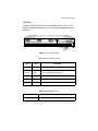
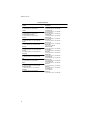
AT-8116 Fast Ethernet Intelligent Switch Installation Guide PN 613-10691-00 Rev A Copyright 1998 Allied Telesyn International Corp. All rights reserved. No part of this publication may be reproduced without prior written permission from Allied Telesyn International Corp. Ethernet is a registered trademark of Xerox Corporation. UNIX is a registered trademark in the United States and other countries licensed exclusively through X/ Open Company Limited. Novell and NetWare are registered trademarks of Novell, Inc. Microsoft and MS-DOS are registered trademarks and LAN Manager and Windows for Workgroups are trademarks of Microsoft Corporation. 3Com is a registered trademark of 3Com. PC-NFS is a trademark of Sun Microsystems, Inc. PC/TCP is a registered trademark of FTP Software, Inc. DECnet is a registered trademark of Digital Equipment Corporation. All other product names, company names, logos or other designations mentioned herein are trademarks or registered trademarks of their respectives owners. Allied Telesyn International Corp. reserves the right to make changes in specifications and other information contained in this document without prior written notice. The information provided herein is subject to change without notice. In no event shall Allied Telesyn International Corp. be liable for any incidental, special, indirect, or consequential damages whatsoever, including but not limited to lost profits, arising out of or related to this manual or the information contained herein, even if Allied Telesyn International Corp. has been advised of, known, or should have known, the possibility of such damages. Electrical Safety and Installation Requirements U.S. Federal Communications Commission RADIATED ENERGY Note: This equipment has been tested and found to comply with the limits for a Class A digital device pursuant to Part 15 of FCC Rules. These limits are designed to provide reasonable protection against harmful interference when the equipment is operated in a commercial environment. This equipment generates, uses, and can radiate radio frequency energy and, if not installed and used in accordance with this instruction manual, may cause harmful interference to radio communications. Operation of this equipment in a residential area is likely to cause harmful interference in which case the user will be required to correct the interference at his own expense. Note: Modifications or changes not expressly approved of by the manufacturer or the FCC, can void your right to operate this equipment. Canadian Department of Communications This Class A digital apparatus meets all requirements of the Canadian InterferenceCausing Equipment Regulations. Cet appareil numérique de la classe A respecte toutes les exigences du Règlement sur le matériel brouilleur du Canada. STANDARDS: This product meets the following standards. RFI Emission EN55022 Class A WARNING: In a domestic environment this product may cause radio interference in which case the user may be required to take adequate measures. Immunity EN50082-1 Electrical Safety EN60950, UL1950 SAFETY ELECTRICAL NOTICES WARNING: ELECTRIC SHOCK HAZARD To prevent ELECTRIC shock, do not remove cover. No user-serviceable parts inside. This unit contains HAZARDOUS VOLTAGES and should only be opened by a trained and qualified technician. To avoid the possibility of ELECTRIC SHOCK disconnect electric power to the product before connecting or disconnecting the LAN cables. iii Electrical Safety and Installation Requirements LIGHTNING DANGER DANGER: DO NOT WORK on equipment or CABLES during periods of LIGHTNING ACTIVITY. INSTALLATION ELECTRICAL—TYPE CLASS 1 EQUIPMENT THIS EQUIPMENT MUST BE EARTHED. Power plug must be connected to a properly wired earth ground socket outlet. An improperly wired socket outlet could place hazardous voltages on accessible metal parts. ELECTRICAL—CORD NOTICE Use power cord, maximum 4.5 meters long, rated 6 amp minimum, 250V, made of HAR cordage molded IEC 320 connector on one end and on the other end a plug approved by the country of end use. CAUTION: Air vents must not be blocked and must have free access to the room ambient air for cooling. FUSE RATING For continued protection against risk of fire replace only with the same type and rating of fuse. OPERATING TEMPERATURE This product is designed for a maximum ambient temperature of 40 degrees C. ALL COUNTRIES: Install product in accordance with local and National Electrical Codes. iv Table of Contents Electrical Safety and Installation Requirements .................................. iii Chapter 1 Introduction .....................................................................................................1 Description...........................................................................................................1 Theory of Operation.............................................................................................2 Features ...............................................................................................................2 Front Panel ..........................................................................................................3 Rear Panel............................................................................................................4 Power Connection ................................................................................................4 Chapter 2 Installation .......................................................................................................5 Verifying Package Contents................................................................................5 Installing the AT-8116 ........................................................................................5 Rack Mounting ....................................................................................................6 Network Connections ..........................................................................................6 Connecting an Ethernet Device to a 10Base-T or 100Base-TX Port .........6 Chapter 3 Applications and Configurations ................................................................9 Applications .........................................................................................................9 Typical Applications ............................................................................................9 Configuring Your Network................................................................................11 Links Between Switches ............................................................................11 Device Configuration.........................................................................................11 Appendix A Technical Specifications .............................................................................13 Appendix B Technical Support Fax Order ....................................................................15 Appendix C Where To Find Us ..........................................................................................17 v Chapter 1 Introduction The AT-8116 is a high-performance 10/100Mbps switch representing the next generation in switching technology. The AT-8116 employs highly-integrated ASIC technology and a Gigabit/sec backplane to significantly boost network performance. Its high density and performance combine with exceptional functionality, such as RMON support, VLAN capabilities and Full Duplex switching, to achieve optimal network switching without expensive changes to the desktop PC or cabling system. The AT-8116 exemplifies the design flexibility which enables deployment as both a departmental and enterprise switch, while enhancing network connectivity. Description The AT-8116 high-density switch features 16 dual-speed 10/100 UTP ports with auto-sensing. Highly-integrated ASIC technology enables a maximum throughput of over 2,000,000pps and 1.6 Gbps. The switch boasts extensive management capabilities, such as the ability to access the learning table and per/port counter statistics, and to set configurations. Built-in RMON support for Groups 1, 2, 3, and 9 allows in-depth analysis of traffic flow, while implementation of the Spanning Tree Algorithm prevents broadcast loops and provides failsafe network redundancy. TERMINAL 8116 RS232C 10BASE-T/100BASE-TX 16 PORT ETHERNET SWITCH with Management POWER 1 2 3 4 5 6 7 8 9 10 11 12 13 14 15 16 100M COLN/FULL DUP LINK ACT Figure 1: AT-8116 Front View 1 Introduction Theory of Operation Ethernet segment switches divide a large local network into smaller segments, insulating each from the other’s local traffic and increasing aggregate bandwidth, while still retaining full connectivity. The AT8116 is designed to be self-configuring and extremely fast, making installation simple and providing an increase in available bandwidth. The switch learns on which port stations are located by remembering the source address of every packet received on every port. When packets are received for stations that the switch has learned, they will be forwarded to only the port on which the station is located. This is in contrast to a hub, which sends every packet to every port. If the switch receives a packet addressed to a station which the switch has not learned, the packet is sent to every port, except the port on which it was received, just as a hub would. This insures that full connectivity is maintained. The high port density of the AT-8116 allows for dedicated high-performance workstation links. Features 2 ❑ Complies with IEEE 802.3 and IEEE 802.3u standards ❑ Sixteen auto-sensing 10/100Mbps UTP ports ❑ All ports operate at wire speed with an aggregate throughput of over 2,000,000pps ❑ Employs highly-integrated ASIC technology; high-speed backplane design; 8 MB of buffer memory ❑ Learning table for up to 8K Mac address entries ❑ Terminal-based Command Line Interface (CLI) management ❑ Spanning tree algorithm prevents broadcast loops and provides fail-safe network redundancy ❑ Port-based VLAN supports broadcast domain VLANs to eliminate network-clogging broadcast storms AT-8116 Installation Guide Front Panel The front panel of the AT-8116 is illustrated below in Figure 2. The following tables describe its various LEDs and components and their functions. TERMINAL 8116 RS232C 10BASE-T/100BASE-TX 16 PORT ETHERNET SWITCH with Management POWER 1 2 3 4 5 6 7 8 9 10 11 12 13 14 15 16 100M COLN/FULL DUP LINK ACT RS232C 100M COLN/Full DUP LINK ACT Power Figure 2: AT-8116 Front Panel Table 1: AT-8116 LEDs and Ports LED Color Description 100M Green ON indicates 100Mbps mode COLN/ FULL DUP Yellow or Green Yellow Blinking for port collision; Green ON when port is configured for Full Duplex LINK Green ON indicates a valid link connection ACT Green Blinking indicates port activity Power Green ON indicates normal operation mode Table 2: RJ45 and RS232 Ports RJ45 16, RJ45 10/100 Mb UTP ports RS232 One, RS232 connection for NMS 3 Introduction Rear Panel The power connection and ON/OFF switch are located on the rear panel of the AT-8116. The two fan holes MUST be kept unobstructed. Power Connection Plug the power cord into an easily accessible outlet and turn on the ON/ OFF switch. 4 Chapter 2 Installation The AT-8116 can operate as a stand-alone unit or in conjunction with any of Allied Telesyn’s other Ethernet and Fast Ethernet offerings. It supports local and SNMP management. Verifying Package Contents ❑ AT-8116 Fast Ethernet Switch ❑ Power cord (for 110V units only) ❑ Rack-mounting brackets ❑ Null modem cable ❑ This installation guide Installing the AT-8116 This section outlines the installation and operation of the AT-8116. The AT-8116 comes as a 19” rack-mounted unit. However, it can be placed in either a rack mount, using the enclosed rack-mount brackets, or on a secure flat surface. Ensure that the unit is within reach of the necessary connections (i.e. power outlet, Ethernet connections, and, if the AT-8116 will be monitored via the serial port, a PC, UNIX workstation, or modem. The unit is powered by a wide-range power supply for either 115 - 240 VAC 50/60Hz, 0.5 A operation. Warning Free air flow must be maintained in order to permit adequate cooling of the unit. FAN holes MUST be unobstructed. 5 Installation Rack Mounting If rack-mounted units are installed in a closed or multi-rack assembly, they may require further evaluation by certification agencies. The following items must be considered: 1. The ambient temperature within the rack may be greater than room ambient temperature. Installation should be such that the amount of air flow required for safe operation is not compromised. The maximum temperature for equipment in this environment is 40°C. Consideration should be given to the maximum rated ambient temperature. 2. Installation should be such that a hazardous stability condition is not inadvertently created due to uneven loading. Network Connections Connecting an Ethernet Device to a 10Base-T or 100Base-TX Port The 10/100Base-TX ports on the AT-8116 are designed to be connected directly to a workstation, using a standard straight-through patch cable. In order to cascade switches or connect a hub to the switch, a crossover cable must be used. The RJ45 ports are defined as MDI-X ports. The cable connections to the 10/100 ports should be UTP Category 5, and cable length is limited to 100 meters on each port. Figure 3 and Figure 4 shows the pin assignments for the RJ45 connector. Note Cables must comply with the ANSI/TIA/EIA specification, commonly referred to as T568A or T568B. 6 AT-8116 Installation Guide Pin # 1 Pin # TD+ 1 2 TD- 2 3 RD+ 3 4 4 5 5 6 RD- 6 7 7 8 8 Figure 3: Straight Cable Connection Between an AT-8116 and a Server/PC 7 Installation Pin # Pin # 1 1 2 2 3 3 4 4 5 5 6 6 7 7 8 8 Figure 4: Crossover Between AT-8116 and Hub or Another Switch 8 Chapter 3 Applications and Configurations Applications A switch boosts network performance by segmenting a single large collision domain into smaller, separate collision domains and providing dedicated connections for intensive networks using work stations and servers. In addition, the Full Duplex capability of Ethernet switches permits connectivity for backbone applications or high throughput for high-performance dedicated servers. The AT-8116 combines 10/ 100Mbps auto-sensing ports with a high-speed backplane design to enable deployment as both a departmental and backbone switch. Typical Applications The AT-8116 seamlessly integrates Fast Ethernet and legacy 10Mbps Ethernet networks, creates a high-performance collapsed Fast Ethernet backbone and drives high bandwidth server farms and power users. Figure 5 illustrates various connection possibilities of the AT-8116. One switch can connect up to sixteen 10/100Mbps UTP ports. Attachments can include 10Mbps and 100Mbps servers, a Fast Ethernet backbone, 10/100Mbps hubs, all functioning in Half or Full Duplex mode. Port connectivity can be over 10Base-T/100Base-TX copper cabling. See Figure 5. 9 Applications and Configurations AT-8116 10/100 Ethernet Switch TERMINAL 8116 RS232C 10BASE-T/100BASE-TX 16 PORT ETHERNET SWITCH with Management POWER 1 2 3 4 5 6 7 8 9 10 11 12 13 14 15 16 100M COLN/FULL DUP LINK ACT To Backbone 100Mbps Local Servers 100Mbps 10/100 Ethernet Switch 100Mbps Stackable Hubs Shared 100Mbps Fast Ethernet Switched 10Mbps Ethernet Figure 5: Various Application Possibilities of the AT-8116 10 AT-8116 Installation Guide Configuring Your Network Links Between Switches An Ethernet to Fast Ethernet switch offers the network administrator a possible upgrade path. At first, the switch can be used simply to segment the existing 10Mbps Ethernet, immediately boosting performance. Next, with the addition of a Fast Ethernet NIC, a file server can be migrated to Fast Ethernet, increasing its availability. As needed, additional file servers or individual users can be moved to Fast Ethernet, while leaving all other parts of the network running 10Mbps as usual. If some of the shared Ethernet segments are still congested, but don’t warrant a full 100Mbps, additional switches can further divide the shared segments, creating a collapsed 100Mbps backbone and small switched 10Mbps segments. Fast Ethernet provides 10 times the bandwidth than regular Ethernet. Software, except for low-level drivers which are always card specific, works with Fast Ethernet without modification. Frames from a device using Fast Ethernet require only physical layer conversion. The AT-8116 combines switched 10/100Mbps technology in a seamless integration of regular Ethernet and the IEEE 802.3u 100Base-TX standard. Device Configuration The AT-8116 provides CLI management. The switch can autosense the speed for each port. However, the switch must be manually configured for the correct duplex mode. For full information on configuring the AT-8116, see the AT-8116 User’s Guide on our website at www.alliedtelesyn.com/ manuals.htm. 11 Appendix A Technical Specifications Table 3 lists the AT-8116 technical specifications. Table 3: AT-8116 Technical Specifications Compatibility IEEE 802.3; IEEE 802.3u (Fast Ethernet Standard) Electrical Rating 115 - 240 VAC, 0.5A Frequency 50 - 60 Hz Power Consumption- 50W Connectors Ethernet Ports RS232 16, RJ45s DB-9 Port LEDs 100M Green ON indicates port is operating at 100Mbps COLN/FULL DUP Yellow/Green Yellow Blinking indicates collision/Green ON indicates Full duplex LINK ACT Green (ON indicates a valid link to software) Green (Blinking indicates port activity) General LED POWER Green ON indicates normal operation Learning Table 8K MAC address Physical 3.5” x 19” x 14.65” (1.5U) 13 Technical Specifications Table 3: AT-8116 Technical Specifications (Continued) Weight 8 lb Environment Operating Temperature 40°C Storage temperature 10°C to 50°C Humidity 85% maximum, non-condensing Standards Compliance UL-1950; EN60500; VCCI; FCC Part 15 Class A 14 Appendix B Technical Support Fax Order Name__________________________________________________________________ Company _______________________________________________________________ Address ________________________________________________________________ City ________________________ State/Province _______________________________ Zip/Postal Code ___________________ Country _______________________________ Phone _______________________________ Fax _______________________________ Incident Summary Model number of Allied Telesyn product I am using _____________________________ Network software products I am using ________________________________________ ______________________________________________________________________ Brief summary of problem _________________________________________________ ______________________________________________________________________ Conditions (List the steps that led up to the problem.) ___________________________ ______________________________________________________________________ ______________________________________________________________________ ______________________________________________________________________ Detailed description (Use separate sheet, if necessary) ______________________________________________________________________ ______________________________________________________________________ ______________________________________________________________________ ______________________________________________________________________ ______________________________________________________________________ ______________________________________________________________________ ______________________________________________________________________ ______________________________________________________________________ When completed, fax this sheet to the appropriate ATI office. Fax numbers can be found on page 17. 15 Appendix C Where To Find Us For Technical Support or Service Location Phone Fax Asia Singapore, Taiwan, Thailand, Malaysia, Indonesia, Korea, Philippines, China, India (+65) 3815-613 (+65) 3833-830 Australia Australia, New Zealand (612) 416-0619 (612) 416-9764 France France, Belgium, Luxembourg, The Netherlands, Middle East, Africa (+33) 1-60-92-15-32 (+33) 1-69-28-37-49 Germany Germany, Switzerland, Austria, Eastern Europe (+49) 30-435-900-126 (+49) 30-435-70-650 Hong Kong (+852) 2-529-4111 (+852) 2 529-7661 Italy Italy, Spain, Portugal, Greece, Turkey, Israel (+39) 2-416047 (+39) 2-419282 Japan (+81) 3-3443-5640 (+81) 3-3443-2443 North America United States, Canada, Mexico, Central America, South America 1 (800) 428-4835 1 (425) 481-3790 United Kingdom United Kingdom, Denmark, Norway, Sweden, Finland, Iceland (+44) 1-235-442560 (+44) 1-235-442490 Techncial Support E-mail Address [email protected] Technical Bulletin Board Service 1 (425) 483-7979 CompuServe Go ALLIED World Wide Web http://www.alliedtelesyn.com For Information Regarding Allied Telesyn International Allied Telesyn International 19015 North Creek Parkway Bothell, WA 98011 Tel: 1 (425) 487-8880 Fax: 1 (425) 489-9191 Allied Telesyn International 950 Kifer Road Sunnyvale, CA 94086 Tel: 1 (800) 424-4284 (USA and Canada) Fax: 1 (408) 736-0100 17 Where To Find Us For Sales Information Australia United States Lindfield, NSW Tel: (612) 416-0619, Fax: (612) 416-9764 Scottsdale, AZ Tel: (602) 423-7087 Fax: (602) 423-7088 Los Angeles, CA Tel: (310) 412-8684, Fax: (310) 412-8685 Mission Viejo, CA Tel: (714) 699-0628, Fax: (714) 699-0276 San Diego, CA Tel: (619) 279-3899, Fax: (619) 279-3897 Santa Ana, CA Tel: (714) 838-0434, Fax: (714) 838-9721 Clearwater, FL Tel: (813) 726-0022, Fax: (813) 726-0234 Norcross, GA Tel: (770) 448-7214, Fax: (770) 448-2600 Reading, MA Tel & Fax: (617) 944-3492 Eden Prairie, MN Tel: (612) 829-7506, Fax: (612) 903-5284 St. Louis, MO Tel: (314) 894-6160, Fax: (314) 894-3773 Dover, NH Tel: (603) 743-3010, Fax: (603) 743-6327 Plaistow, NH Tel: (603) 382-0815, Fax: (603) 382-0818 Portsmouth, NH Tel: (603) 431-6461, Fax: (603) 431-1649 Morrisville, NC Tel: (919) 468-0831, Fax: (919) 468-0829 Lake Oswego, OR Tel: (503) 699-3130, Fax: (503) 636-6575 Austin, TX Tel: (512) 261-6378, Fax: (512) 261-6379 Dallas, TX Tel: (214) 365-9471, Fax: (214) 365-9472 San Antonio, TX Tel: (210) 646-8744 Vienna, VA Tel: (703) 506-0196, Fax: (703) 506-1986 Canada Rexdale, Ontario Tel: (416) 675-6738, Fax: (416) 675-0057 Richmond, British Columbia Tel: (604) 244-0678, Fax: (604) 270-3644 England Abingdon, Oxon Tel: (+44) 1235-442500, Fax: (+44) 1235-442590 France Les Ulis Tel: (+33) 1-60921525, Fax: (+33) 169-28-37-49 Germany Berlin Tel: (+49) 30-435-90-00, Fax: (+49) 30-435-706-50 Freising Tel: (+49) 8161-9906-0, Fax: (+49) 8161-9906-22 Hong Kong Mongkok Tel: (+852) 2-529-4111, Fax: (+852) 2-529-7661 Italy Milano Tel: (+39) 2-416047, Fax: (+39) 2-419282 Japan Machida-shi, Tokyo Tel: (+81) 427-21-8141, Fax: (+81) 427-21-8848 Yodogawa-ku, Osaka Tel: (+81) 6-391-6310, Fax: (+81) 6-391-6325 Singapore Tel: (+65) 383-3832, Fax: (+65) 383-3830 18