1
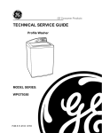
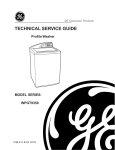
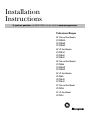
Installation
Instructions
If you have questions, call 800-GE-CARES or visit our website at: www.monogram.com
Professional Ranges
48" Natural Gas Models
ZDP48N4G
ZDP48N6R
ZDP48N6D
48" LP Gas Models
ZDP48L4G
ZDP48L6R
ZDP48L6D
36" Natural Gas Models
ZDP36N6
ZDP36N4R
ZDP36N4D
36" LP Gas Models
ZDP36L6
ZDP36L4R
ZDP36L4D
30" Natural Gas Model
ZDP30N4
30" LP Gas Model
ZDP30L4
Installation Instructions
BEFORE YOU BEGIN
CAUTION:
Read these instructions completely and
carefully.
THESE RANGES SHOULD BE INSTALLED
IN CONJUNCTION WITH A SUITABLE
OVERHEAD VENT HOOD. Due to the high heat capacity
of this unit, particular attention should be paid to the
hood and duct work installation to assure it meets
local building codes.
• IMPORTANT – Save these instructions for
local inspector’s use.
• IMPORTANT – Observe all governing codes
•
•
•
•
•
•
MISE EN GARDE :
and ordinances.
Note to Installer – Be sure to leave these
instructions with the Consumer.
Note to Consumer – Keep these instructions for
future reference.
Skill Level – Installation of this range requires basic
mechanical and electrical skills.
Completion time – 1 to 3 hours.
Proper installation is the responsibility of the installer.
Product failure due to improper installation is not
covered under the Warranty.
CES CUISINIÈRES DOIVENT ÊTRE
MONTÉES CONJOINTEMENT AVEC UNE
HOTTE À ÉVACUATION DE PLAFOND APPROPRIÉE.
Étant donné la grande capacité thermique de cet
appareil, une attention particulière doit être portée
au montage de la hotte et du système de gaines pour
s’assurer qu’il est conforme aux codes du bâtiment
locaux.
Standard countertop and island installations:
A 1200 CFM hood is recommended for 48" ranges.
A 600 CFM hood is recommended for 30" and 36" Ranges.
WARNING:
This appliance must be properly grounded.
See “Electric Supply”, page 7.
Hoods should be 24" min. deep and the same width as
the cooktop.
AVERTISSEMENT :
Check local building codes for the proper method of
gas range installation. Local codes vary. Installation,
electrical connections and grounding must comply
with applicable codes. In the absence of local codes,
the gas range should be installed in accordance with
the National Fuel Gas Code ANSI 223.1, latest
edition and National Electrical Code ANSI/NFPA 70,
latest edition.
Cet appareil doit être mis à la terre
adéquatement. Voir la section « Alimentation
électrique » à la page 7.
For Monogram local service in your area,
1.800.444.1845.
For Monogram Service in Canada, call
1.888.880.3030.
For Monogram Parts and Accessories, call
1.800.626.2002.
CAUTION:
These ranges weigh up to 600 pounds.
Some disassembly will reduce the weight
considerably. Due to the weight and size of the range
and to reduce the risk of personal injury or damage
to the product, TWO PEOPLE ARE REQUIRED FOR
PROPER INSTALLATION.
If you received a damaged range, you should contact
your dealer.
In the Commonwealth of Massachusetts:
• This product must be installed by a licensed plumber
or gas fitter.
• When using ball type gas shut off valves, they shall
be T-handle type.
• A flexible gas connector, when used, must not
exceed 3 feet.
MISE EN GARDE :
Ces cuisinières pèsent jusqu’à
272 kg (600 lb). Tout démontage réduira
considérablement leur poids. En raison du poids et
de la taille de la cuisinière, dont la manipulation risque
d’entraîner des lésions corporelles ou des dommages
au produit, DEUX PERSONNES SONT NÉCESSAIRES
POUR PROCÉDER À UN MONTAGE ADÉQUAT.
2
Design Information
Installation Instructions
Step 1, Remove Packaging ..............................................8
Step 2, Level the Range ....................................................9
Step 3, Install Anti-Tip Device ..................................9, 10
Step 4, Connect Range to Gas ......................................11
Step 5, Connect Electrical ..............................................12
Step 6, Slide Range into Position ................................12
Step 7, Replace Oven Doors ..........................................12
Step 8, Assemble and Adjust Burners ........................13
Finalize Installation..........................................................13
Installation Checklist ......................................................14
Install Backsplash Accessory ......................................15
CONTENTS
Design Information
Models Available ..............................................................3
Accessory Requirements ................................................3
Product Dimensions and Clearances ........................4, 5
Advance Planning ............................................................6
Tools and Materials Required ...................................... 6
Installation Preparation
Power Supply Locations ..................................................7
MODELS AVAILABLE
36" Natural Gas Models:
These ranges are factory set for either natural
gas or liquid propane gas. Order the model for your
installation situation.
ZDP36N6 – 6 gas burners
ZDP36N4R – 4 gas burners and grill
ZDP36N4D – 4 gas burners and griddle
48" Natural Gas Models:
36" Liquid Propane Gas Models:
ZDP48N4G – 4 gas burners, grill and griddle
ZDP48N6R – 6 gas burners and grill
ZDP48N6D – 6 gas burners and griddle
ZDP36L6 – 6 gas burners
ZDP36L4R – 4 gas burners and grill
ZDP36L4D – 4 gas burners and griddle
48" Liquid Propane Gas Models:
30" Natural Gas Model:
ZDP48L4G – 4 gas burners, grill and griddle
ZDP48L6R – 6 gas burners and grill
ZDP48L6D – 6 gas burners and griddle
ZDP30N4
30" Liquid Propane Gas Model:
ZDP30L4
BACKSPLASH ACCESSORIES
Backsplash for 30" Models:
ZX9B30HSS – 9" high backsplash
ZX22B30HSS – 22" high backsplash with warming shelf
(2 piece)
All models require 12" min. clearance to a vertical
combustible surface at the rear. A backsplash
accessory is available for installations with less
than 12" clearance to the back wall. Order a 12" high
backsplash or 22" high backsplash with warming shelf.
Backsplash for 48" Models:
22" High Backsplash With
Warming Shelf
ZX12B48HSS – 12" high backsplash
ZX22B48HSS – 22" high backsplash with warming shelf
(2 piece)
Backsplash for 36" Models:
ZX12B36HSS – 12" high backsplash
ZX22B36HSS – 22" high backsplash with warming shelf
(2 piece)
12" High Backsplash
(9" High for 30" Models)
INSTALLATION NOTE:
A custom backspash may be constructed of non-combustible back wall materials such as ceramic tile, brick, marble
or other stone.
3
Design Information
PRODUCT DIMENSIONS AND CLEARANCES
36" Wide Range Models
48" Wide Range Models
22"
Optiona
sh
l Backspla
22"
Backs
Optional
12"
plash
1-1/2"
12"
1-1/2"
35-1/4"-36-3/4"
35-1/4"-36-3/4"
47-7/8"
28-1/4"
28-1/4"
35-7/8"
48" and 36" Range Models
29-1/16"
12" Min. to Combustibles or
0" Min. to Combustibles
with 12" or 22" Backsplash
36" Min.
to
Combustibles
9-1/2"
3/4"
22" High
Backsplash
with Shelf
22"
36" Min.
to Combustibles
12"
Backguard
12" High Backsplash
0" Clearance
0" Clearance
26"
NOTE: 12" Min. to Combustibles or
0" Min to Combustibles with any
backsplash accessory or custom
non-combustible back wall.
28-1/4"
31-1/2"
45-5/8"
4
Design Information
PRODUCT DIMENSIONS AND CLEARANCES
30" Wide Range Models
22"
Ba
Optional
cksplash
27-3/8"
9-1/2"
3/4"
22" High
Backsplash
with Shelf
9"
22"
36" Min.
to Combustibles
1-1/2"
9"
9" High Backsplash
35-1/4"-36-3/4"
0" Clearance
26-3/4"
29-7/8"
26-3/4"
29-1/4"
43-7/8"
NOTE: Refer
to Vent Hood
Installation
Instructions
for hood height
above the range.
30" Wide Range Hood
Or
36" Wide Range Hood
Or
48" Wide Range Hood
18" Min.
30"/36" Wide Models 4"
48" Wide Models 8"
30" Wide Models 8"
36" Wide Models 12"
48" Wide Models 16"
30" Wide Models 4"
36" Wide Models 4"
48" Wide Models 8"
12"
13"
Max.
12" Min. to
Combustible
Material
Each Side
Cooking Surface
4"
1-1/2"
Electrical Supply
Gas Supply
35-3/8" Max. for Counter Level
36-3/4" Max. with Range Leveling Legs Fully Extended
5
36" Min. to
Combustible
Material From
Cooking Surface
Design Information
ADVANCE PLANNING
TOOLS REQUIRED
Refer to “Dimensions and Clearances” for appropriate
placement and necessary clearances when planning
the installation.
• Saw
• Measuring tape
• Carpenter’s square
• Pipe wrench
• Large flat-blade screwdriver
• Safety glasses
• Drill and appropriate bits
• Cabinetry can not be installed directly above the
range.
• We recommend the installation of a vent hood above
the surface.
– The vent hood must be at least 24" deep.
– The vent hood must be at least the same width as
the range.
– For 48" models, we recommend the vent hood
blower be 1200 CFM.
MATERIALS REQUIRED
(not supplied)
– For 30" and 36" models, we recommend the vent
hood blower be 600 CFM.
• Pipe and fittings as required
• Manual gas line shut-off valve
• Gas pressure regulator (supplied)
• Gas-resistant pipe joint sealant
• 5 foot, 5/8" AGA-certified flexible metal gas supply line
– If required by local codes, use solid pipe fittings.
• Working areas adjacent to the range should have
18" minimum clearance between countertop and
cabinet bottom.
• Clearance between range and side wall or
combustible material must be at least 12" on
each side.
NOTE: Purchase new flexible line. DO NOT USE OLD,
PREVIOUSLY USED FLEXIBLE LINE.
• Allow 12" min. clearance at the back to combustible
materials.
• Allow 36" min. above the cooking surface to
combustible materials.
• Installation must conform with local codes. In the
absence of local codes, the range must comply with
the National Fuel Gas Code, ANSI Z223.1/NFPA.54,
latest edition. In Canada, installation must conform
with the current Natural Gas Installation Code,
CAN/CGA-B149.1 or the current Propane Installation
Code, CAN/CGA-B149.2, and with local codes where
applicable. This range has been design-certified by
CSA International according to ANSI Z21.1, latest
edition and Canadian Gas Association according
to CAN/CGA-1.1 latest edition.
6
Installation Preparation
POWER SUPPLY LOCATIONS
If the electrical service provided does not meet the
above specifications, it is recommended that a
licensed electrician install an approved outlet.
Gas Supply:
• The natural gas models are designed to operate at 5"
water column pressure. A regulator is required at the
natural gas source to provide a maximum of 7" water
pressure to the cooktop regulator.
• Locate the electric supply as illustrated.
WARNING:
The range is
equipped for use with an electrical supply
which uses a separate grounding conductor
(4 wire system).
• The liquid propane models are designed to operate at
10" water column pressure. A regulator is required at
the LP source to provide a maximum of 14" water
pressure to the cooktop regulator.
If this range must be connected to an electrical
system which utilizes a single conductor for ground
and neutral (3 wire system), the grounding jumper at
the terminal block must be connected. The grounding
jumper is located behind the front kick panel.
• These gas ranges are supplied with 1/2" NPT female
gas connection located at the left rear corner.
• A minimum 5/8" dia. metal flexible line is required.
AVERTISSEMENT :
• Locate pipe stub on the back wall as illustrated.
Étant donné sa conception, la cuisinière
exige que l’alimentation électrique soit
dotée d’un conducteur de terre distinct (système à
4 fils).
– Use 5-foot, 5/8" long flexible gas supply line.
• Install a manual shut-off valve in the gas line, in an
easily accessible location.
Si cette cuisinière doit être connectée à un système
électrique qui utilise un conducteur simple pour la
mise à la terre et le conducteur neutre (système à
3 fils), il faut alors connecter le cavalier de terre sur
la plaque à bornes. Le cavalier de terre est situé
derrière le panneau de protection frontal.
4″ for 30″/36″ Models
8″ for 48″ Models
12″
2″ Maximum
Protrusion From
Wall For Gas Supply
Flex Line
to Range
8″ for 30″ Models
12″ for 36″ Models
16″ for 48″ Models
Gas Supply
4″ for 30″/36″
Models
8″ for 48″
Models
Green
Electrical
Supply
Red
White
4″
NEMA 14-50R
Receptacle
Connect Here
1-1/2″
Terminal Block
Electric Supply:
To connect grounding jumper:
These ranges must be supplied with 208/240 volt, 60 Hz.,
and connected to an individual, properly grounded
branch circuit protected by a circuit breaker or time
delay fuse (50 amp for 48" ranges, 30 amp for 36" ranges
and 25 amps for 30" ranges). The receptacle must be
a NEMA 14-50R device to accept the 4-prong plug
supplied with the range.
• Disconnect restraining clip holding jumper.
• Connect green jumper to open terminal on
neutral (white) portion of the terminal block.
7
Black
Installation
STEP 1 REMOVE PACKAGING
Slot
Before moving the range indoors:
• Remove outer carton and packing material from the
shipping base.
Hinge lock
Pull the hinge locks
down to unlock.
Remove oven doors:
• Fully open the door.
• Each hinge has a hinge lock. Close the hinge latch
down against the door frame.
• Firmly grasp the door at the top sides.
Kick Panel
• Close the door to the near-vertical position.
• Remove the kick panel by removing 2 screws at the top
and pulling forward.
• Lift the door up and pull straight out.
Range Must
be Uniformly
Supported
on Braces
Left Rear Shipping
Screws
22"
Leveling Legs
Due to the weight of these ranges, use a dolly with
soft wheels to move this range.
The range is secured to the skid with 2 bolts in the front
and 2 “L” brackets on the bottom flange of the range
back. Remove bolts and “L” brackets.
• Lift the range onto the dolly and move indoors.
• Remove the panel from the rear of the shipping pack.
Lay the panel on the floor directly in front of the
installation location. The range should be placed
on this panel to prevent damage to the floor.
To simplify handling and to reduce the weight of
the range:
• Remove the grates and the drawers below the knobs
(on grille and griddle models).
• Remove the two strips from the oven interior. Place
the strips on the floor at the left and right sides of the
installation location. These strips provide a surface
for sliding the range into the final position and will
prevent damage to the floor. The leveling legs must
rest permanently on these runner strips.
• Remove grill and griddle covers. DO NOT ATTEMPT
TO REMOVE A GRILL OR GRIDDLE ASSEMBLY.
• Remove the broiler pans/literature package from
inside oven(s).
Range
Opening
Runners
To Support
Leveling Legs
Panel
8
Installation
STEP 2 LEVEL THE RANGE
NOTE: Rear range leveling legs are not accessible after
installation.
• Adjust the height of the range to countertop height
or higher.
• Check to be sure the adjoining cabinets/countertops
are level, front to back and left to right across the
opening of the range.
IMPORTANT: The range should always be installed
at countertop height or higher. DO NOT INSTALL THE
RANGE LOWER THAN ADJACENT COUNTERTOP
HEIGHT.
• Measure the distance from the floor to the top of the
countertop in the left and right rear corners.
The anti-tip bracket is designed to be installed on
top of the slide (runners) provided with the range.
Any other type of construction may require special
installation techniques to insure adequate fastening
of the anti-tip bracket to the floor or wall.
STEP 3 INSTALL ANTI-TIP DEVICE
WARNING:
• The bracket must be properly installed to prevent
tipping of the range.
• All Ranges Can Tip
• Injury Could Result
• Read the AHAM Anti-Tip Safety brochure packed
with the product.
• Install Anti-Tip Bracket
Provided
All Ranges must have an anti-tip device correctly
installed according to these instructions.
• See Instructions
• If the range is pulled out from the wall for any
reason, make sure that the device is properly
engaged when pushed back against the wall or
installation position.
AVERTISSEMENT:
• If the anti-tip device is not engaged, there is a
possible risk that the range can tip over and
cause injury if you or a child stand, sit or lean on
an open door.
• Toutes les cuisinières peuvent
basculer
[4] #10 x 2" wood
screws
• Des blessures peuvent en
résulter
• Montez le support
antibasculement fourni
Anti-Tip Bracket
• Consultez les instructions
AHAM Anti-Tip
Safety Brochure
9
Installation
STEP 3 INSTALL ANTI-TIP DEVICE
(CONTINUED)
Small Hole For Wood (2) Wood Screws into
Installations (2 Total) Back Wall
(All Installations)
(2) Large Holes For
Concrete Installations
Back
Wall
Small Holes For Wood
Installations (2 Total)
Wood
Slide
Strip
f
ide O
iR ght S nge
o r Ra
Wall
Dimension A
A=
Models
1/2"
5/8"
1/4"
ZDP48
ZDP36
ZDP30
Dimension A
Wood Construction:
Concrete or Cement Construction:
• Place the bracket against the back wall, into the right
rear corner of the installation location.
Hardware Required (not supplied):
[2] sleeve anchors, lag bolts and washers.
• See Dimension A, position the bracket the correct
distance from the right side. Mark the 2 small screw
holes for fastening the bracket to the floor and remove
the bracket.
• Place the bracket against the back wall, into the
right rear corner of the installation location.
• See Dimension A, position the bracket the correct
distance from the right side. Mark the 2 large holes
for fastening the bracket to the floor and remove
the bracket.
• Drill two, 1/8" diameter pilot holes.
• Fasten the bracket securely to the floor and wall using
all 4 screws provided.
• Drill recommended size holes for the hardware.
• Install the sleeve anchors into the holes and then
install the lag bolts through the bracket. The bolts
must be properly tightened as recommended for
the hardware.
• Fasten the bracket securely to the floor.
• Drive wood screws into the back wall.
10
Installation
STEP 4 CONNECT RANGE TO GAS
Assure that gas supply is turned off at the shut-off
valve:
CAUTION:
• Connect flexible metal connector to incoming gas line
pipe stub located on the left side on the bottom back
of the range.
MISE EN GARDE :
Do not use a flame to check for gas leaks.
Il ne faut pas utiliser de flamme pour
vérifier s'il y a des fruites.
• Turn on gas and check for leaks:
– Use a liquid leak detector at all joints and
connections in the system.
NOTE: This range is equipped with a gas shut-off valve
located behind the kick plate. This valve is to be used
in the event that service is required in the future.
Pipe Stub
11
Installation
STEP 5 CONNECT ELECTRICAL
STEP 7 REPLACE OVEN DOOR(S)
Plug power cord into properly grounded receptacle.
IMPORTANT: Do not lift the door by the handle.
To replace the oven doors:
• Firmly grasp the door at the top sides. This is critical.
• Approach the range with the door angled in a vertical
position.
• Guide the hinges into the slots.
• Push the door in firmly while opening.
• Once in position, open the door completely. Push the
hinge locks back in and towards the front frame.
STEP 6 SLIDE RANGE INTO
POSITION
• Carefully, slide the range into position.
– Be careful not to entangle power cord and gas
flexible tubing.
• Be sure the right rear leg is engaged in the slot of the
installed anti-tip bracket.
• Check for proper installation by grasping the range
at the top front edge and carefully attempt to tilt the
range forward.
• Check to be sure the front of the range is level.
Adjust front leveling legs accordingly.
• Replace the front kick panel by reversing the
procedure described in Step 1.
CAUTION:
Take care when replacing the oven doors.
If the hinge latch is not securely locked,
the hinge may snap back and separate. If the hinge
separates, you must apply pressure (possibly with
your foot) to press it back together and then engage
the hinge latch.
MISE EN GARDE :
Soyez prudent lorsque vous remettez en
place les portes du four. Si le loquet de
charnière n’est pas verrouillé correctement, la
charnière peut se dégager brusquement et se séparer.
Si c’est le cas, vous devez exercer une pression
(par exemple avec le pied) pour la remettre en place,
puis enclencher le loquet.
12
Installation
STEP 8 ASSEMBLE AND ADJUST BURNERS
Assemble burners as shown. Check to be sure that
burner heads and caps are securely seated. Pin(s) must
completely engage holes to ensure proper assembly.
Burner Cap
Burner Head
(Brass)
• Check for proper ignition:
– Push in one control knob and turn 90° to LITE
position.
– The igniter will spark and the burner will light; the
igniter will cease sparking when the burner is lit.
– First test may require some time, while air is flushed
out of the gas line.
– Turn knob to OFF.
– Repeat the procedure for each burner.
Locator Pins
Burner Ring
(Aluminum)
IMPORTANT: If the ignitor electrodes continue to
spark after the burners are lit, check that each burner
component is assembled and seated properly by
observing constant gaps between each layer.
Disassemble and reassemble as required.
To aid reassembly, each brass burner
head is marked with a clock face.
Replace the burner head with the
arrow pointing to the rear of the
cooktop (12 o’clock position).
• Burner flames should be blue and stable with no
yellow or yellow tips, excessive noise or lifting of the
flame from the burner. If any of these conditions exist,
check that the burner ports are not blocked. If one of
these conditions continues, call for service.
13
Installation
FINALIZE INSTALLATION
Place the burner grates over the burners. Press corner
of the grate to the cooktop. The grates should be seated
and should not rock.
The grill and griddle are secured with screws at the
front. They are designed to be stationary and should not
be removed.
The griddle has two leveling screws beneath the rear
flue cover that can be used to adjust to the desired slope.
The center screw is for shipping purposes only and can
be removed.
INSTALLATION CHECKLIST
❑ Double check to make sure everything in this manual
has been completed. Rechecking steps will ensure
safe use of the range.
❑ When ordering parts, always include the serial
number, model number and a code letter to ensure
proper replacement parts.
❑ Make sure all controls are left in the OFF position.
❑ Recheck Steps:
Double check to make sure everything in this manual
has been completed. Rechecking steps will ensure
safe use of the range.
❑ Make sure the flow of combustion and ventilation air
to the range is unobstructed.
❑ The serial plate is located beneath the ledge trim on
the left side, just above the left knob. In addition to the
model and serial numbers, it tells you the ratings
of the burners and the type of fuel and pressure the
range was adjusted for when it left the factory.
14
Installation
INSTALL 9” or 12” HIGH BACKSPLASH
• Install and level the range or cooktop according to the
installation instructions.
• Remove the backsplash packaging. Select the back, wall
mount panel with mounting screw slots.
• Mark a horizontal line on the wall, 1/8" above the
range/cooktop backguard.
• Use wood screws or fasteners (not supplied) to secure
the back section to the wall. Slide the panel up or down
to provide the 1/8" gap between the top of the
range/cooktop and the bottom of the backsplash.
This 1/8" gap allows the appearance or front section
to overlap the mounted rear panel.
• Secure the appearance panel to the mounted back
section with the # 8 self-tapping screws provided. Install
3 screws on each side and 5 across the top.
Slots for Vertical
Adjustment
Back section
1/8"
Backguard
Supplied
#8 Screws
Front section
Back
section
INSTALL 22” HIGH BACKSPLASH
• Install and level the range or cooktop according to the
installation instructions.
• Remove the backsplash packaging. Select the back, wall
mount panel with mounting screw slots.
• Mark a horizontal line on the wall, 1/8" above the
range/cooktop backguard.
• Use wood screws or fasteners (not supplied) to secure
the back section to the wall. Slide the panel up or down
to provide the 1/8" gap between the top of the
range/cooktop and the bottom of the backsplash.
This 1/8" gap allows the appearance or front section
to overlap the mounted rear panel.
• Attach the shelf to the front section of the backsplash
using screws and nuts supplied.
• Secure the appearance panel to the mounted back
section with the # 8 self-tapping screws provided. Install
3 screws on each side and 5 across the top.
Supplied
#8 Screws
Slots for
Vertical
Adjustment
Back
section
1/8"
Backguard
Holes
Nut
Screw
WARNING:
Front section
Back
section
The back section must be securely fastened to
the wall. Failure to do so could cause damage or
personal injury. Maximum shelf weight capability
is 10 lbs.
AVERTISSEMENT :
Supplied
#8 Screws
La section arrière doit être fixée solidement
sur le mur. Le défaut de procéder ainsi peut
causer des dommages matériels ou des lésions
corporelles. La capacité de charge maximale
de l’étagère est de 4,5 kg (10 lbs ).
15
NOTE: While performing installations described in this book,
safety glasses or goggles should be worn.
For Monogram ® local service in your area, call
1.800.444.1845.
NOTE: Product improvement is a continuing endeavor at
General Electric. Therefore, materials, appearance and
specifications are subject to change without notice.
Pub. No. 49-80222-1
Part No. 164D4290P374
17681 Rev. B
12-04 JR