1
GE Monogram
Installation
Instructions
Professional
Ranges
48" Natural
Gas Models
ZDP48N4G
ZDP48N6R
ZDP48N6D
48" LP Gas Models
ZDP48L4G
ZDP48L6R
ZDP48L6D
36" Natural
Gas Models
ZDP36N6
ZDP36N4R
ZDP36N4D
36" LP Gas Models
ZDP36L6
ZDP36L4R
ZDP36L4D
30" Natural
Gas Modal
ZDP3ON4
30" LP Gas Modal
ZDP30L4
®
Before you begin--Read
these instructions completely and carefully.
IMPORTANT: Save these instructions for local inspector's use.
IMPORTANT: OBSERVE ALL GOVERNING CODES AND ORDINANCES.
NOTE TO INSTALLER: Be sure to leave these instructions with the Consumer.
NOTE TO CONSUMER: Keep these instructions
reference.
F!l,,,t:s,,u_,:_l This appliance
must
be properly
grounded.
See "Electric
For Monogram local service in your area,
1-800-444-1845.
For Monogram Service in Canada,
Call 1-888-880-3030.
For Monogram Parts and Accessories,
1-800-626-2002.
If you received a damaged
contact your dealer:
CAUTION:
THESE RANGES SHOULD
call
range, you should
BE INSTALLED
IN CONJUNCTION
WITH A SUITABLE
OVERHEAD VENT HOOD. Due to the high
heat capacity of this unit, particular attention
should be paid to the hood and duct work
installation to assure it meets local building
codes.
Standard countertop and island installations:
A 1200 CFM hood is recommended
for 48"
ranges.
A 600 CFM hood is recommended
with your Owner's Manual for future
for 30" and
36" Ranges.
Hoods should be 24" min. deep and the same
width as the cooktop.
Supply",
page 7.
Installation of this range requires basic
electrical, carpentry and mechanical skills.
Proper installation is the responsibility of the
installer. Product failure due to improper
installation is not covered under the GE
Appliance Warranty.
for details.
See the Owner's
Manual
grounding must comply with applicable codes.
In the absence of local codes, the gas range
should be installed in accordance with the
National Fuel Gas Code ANSI 223.1, latest
edition and National Electrical Code ANSI/
NFPA 70, latest edition.
CAUTION:
These ranges weigh up to 600 pounds. Some
disassembly
will reduce the weight considerably. Due to the weight and size of the range
and to reduce the risk of personal
itl,jury or
damage
to the product,
TWO PEOPLE ARE
REQUIRED
FOR PROPER INSTALLATION.
Check local building codes tor the proper
method of gas range installation. Local codes
vary. Installation, electrical connections and
Contents"
Design
Models
Information
Available ..................................................................................................................................
Accessory
Requirements
.....................................................................................................................
Models Dimensions
and Clearances
...............................................................................................
Advance Planning
Tools & Materials
...............................................................................................................................
Required
................................................................................................................
Installation Preparation
Power Supply Locations ......................................................................................................................
3
3
4,5
6
6
7
Installation
Step
Step
Step
Step
Step
Step
Step
1:
2:
3:
4:
5:
6:
7:
Remove Packaging ..................................................................................................................
Level the Range ......................................................................................................................
Install _mti-Tip Device ............................................................................................................
Connect
Range to Gas ..........................................................................................................
Install the Range Backguard
................................................................................................
Connect
Electrical
................................................................................................................
Slide Range Into Position
....................................................................................................
Step 8: Replace Oven Doors .............................................................................................................
Step 9: _ssemble
& Adjust Burners
.................................................................................................
Step 10: Adjustable
Low Burner Settings
........................................................................................
Finalize Installation
...........................................................................................................................
8
9
9
11
11
12
12
12
13
13
13
2
Design
Information
Pr@ssional
Models"
Available
These ranges are factory set fbr either natural
gas or liquid propane
gas. Order the model
for your installation
situation.
36" Natural
ZDP36N6
48" Natural
ZDP36N4R
Gas Models:
ZDP48N4G
grill and griddle
and grill
4 gas burners
6 gas burners
and grill
36" Liquid
ZDP36L6
ZDP48N6D
6 gas burners
48" Liquid
ZDP48L4G
and griddle
Propane
and griddle
Propane
ZDP36L4R
Gas Models:
grill and griddle
and grill
ZDP36L4D
ZDP48L6R
4 gas burners
6 gas burners
Gas Models:
6 gas burners
4 gas burners
4 gas burners,
and grill
and griddle
30" Natural
ZDP48L6D
Gas Model:
ZDP30N4
6 gas burners
Requirements
6 gas burners
ZDP36N4D
ZDP48N6R
A ccesso, 7
Gas Models:
4 gas burners
4 gas burners,
Ranges
and griddle
30" Liquid
ZDP30L4
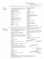
All models require the installation of a backguard. A backguard should be ordered at the
same time as the range. Both must be on site
at the time of installation.
Order one backguard
ZXIB48
1-1/2" high
installations
such
as brick,
ceramic
tile,
Gas Model:
Order one backguard
ZX1B30
1-1/2" high
installations
for 30" Models:
backguard
(required
for island
or installations
where back wall is
non-combustible
marble,
etc.)
for 48" Models:
backguard
(required
for island
or installations
where back wall is
non-combustible
marble,
etc.)
Propane
such
as brick,
ceramic
tile,
ZX12B30
9" high
backguard
ZX22B30
22" high
backguard
with warming
shelf
ZX12B48
12" high
backguard
ZX22B48
22" high backguard
(2 piece)
with warming
Order one backguard
ZXIB36
1-1/2" high
installations
shelf
2 hgB;':gf
00rdW
for 36" Models:
backguard
(required
for island
or installations
where back wall is
non-combustible
marble,
etc.)
such
as brick,
ceramic
tile,
12"High13ackguard
(9" Highfor 30" Models)
ZX12B36
12" high
backguard
_rd
ZX22B36
22" high backguard
(2 piece)
Installation
Note:
with warming
for
shelf
For approved
installations
to non-combustible
back wall materials,
material
representative
to ensure that the material
has appropriate
to staining and/or
discoloration.
IslandInstallatioasonly
consult
resistance
Design
Information
Pr@ssional
Ranges
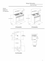
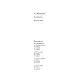
Product
Dimensions
1/4"
& Clearances
ii
Optionalt
35-1/4"-30-3/4"
48" Wide Range Models
36"Wide RangeModels
_29-1/16"
3-1/4" q_i 12"_
_
21-1/4"
High
Shelf
30" Min.
to Combustibles
12" Min to Combustibles
Without BackguardorO"
to Non-CombustibleWall
with 1-1/2" Backguard 36" Min
to
LowBack
--
Combustibles
0" Clearance
All Models
26"
28-1/4'm
31-1/2'm
45-518"
48" and 36" Range Models
Design
Information
Pro/essional
Ranges
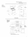
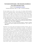
Product
_27-3/8"
Dimensions
& Clearances"
-_
21-1/4"
_High
36" Min.
to Combustibles
Shelf
LowBack
35-I/4"-36-8/4"
--
o" Clearance
i
i
26-8/4"
,
_
9-7/B"
\
r_q
r_q
--26-3/4'm
--29-1/4"
43-7/8"
30" Wide Range Models
Note: Refer to Vent
Hoed Installation
Instructions for
/
Or
36" WideRangeHood
hood height above
the range.
,
48" WideRangeHood
I
\
\
\
30" WideRangeHood
30"/36" Wide Models4'_
48" Wide Models8"
0
i
,' 30"/36"Wide Models12"
48" WideModels 16"
i
18" Min.
•
30/36 WldeModels4
48 Wide Models8
,I
,
i
i
,
i
12%
,
i
i
i
_i
_
i
i
i
i
36" Min. to
Combustible
Material From
CookingSurface
12"Min.to
t Matedal
i EachSide
i
i
i
o
o
8-1/2"
ElectricalSupply
GasSupply
\
"_ 35-3/8"Max.for CounterLevel
36-3/4"Max.with RangeLevelingLegsFullyExtended
Design
Information
Pr@ssional
Advance
Planning
Refer to "Dimensions
and Clearances"
for
appropriate
placement and necessary clearances when planning the installation.
• Cabinetry can not be installed directly above
the range.
• We recommend
the installation of a vent
hood above the surface.
-The vent hood must be at least 24" deep.
-The vent hood must be the same width as
the range.
-For 48" models, we recommend
hood blower be 1200 CFM.
• Allow 36" min. above the cooking surface to
combustible materials.
• For 48" models, we recommend
the vent
hood blower be 1200 CFM.
• For 30" and 36" models, we recommend
the
vent hood be 600 CFM.
• Installation
must conform with local codes.
In the absence of local codes, the range
must comply with the National Fuel Gas
Code, ANSI Z223.1, latest edition.
the vent
-For 30" and 36" models, we recommend
vent hood blower be 600 CFM.
Ranges
the
A.G.A. approved.
• Working areas adjacent to the range should
have 18" minimum clearance between
countertop
and cabinet bottom.
• Clearance between range and side wall or
combustible material must be at least 12" on
each side.
If the range is installed in an island:
• Allow 12" min. clearance at the back to
combustible materials.
7bols &
Materials
.%qui, d:
• Saw
•
•
•
•
•
•
•
•
•
Measuring
tape
Carpenter's
square
Pipe and fittings as required.
Manual gas line shut-off valve.
Gas pressure
regulator
(supplied)
Large flat-blade
screwdriver
Pipe wrench
Drill and appropriate
bits
Safety glasses
• Gas-resistant
pipe joint sealant
• 5 foot, 5/8" AGA-certified
flexible metal gas
supply line.
-If required
by local codes, use solid pipe
fittings.
Note: Purchase
new flexible line. DO NOT
USE OLD,
LINE.
PREVIOUSLY
USED
FLEXIBLE
Installation
Preparation
Pro/essional
Pozogr
Supply
Locations
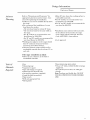
Gas Supply:
• The natural gas models are designed
to
operate
at 6" to 14" water column
pressure.
• The liquid propane
models are designed
to
operate
at 11 to 14" water column
pressure.
A regulator
is required
at the L.R source to
provide a maximum
of 14" water pressure
to
the range regulator.
Ranges
4" For30"/36"Models
8"Models
12_Flex
Supply ///t0
Line
Range
16" For48" Models
Electrical_
• These gas ranges are supplied with
NPT female gas connection
located
left rear cornet:
• A minimum 5/8" dia. metal flexible
required.
• For flexible connection, locate pipe
the back wall as illustrated.
1/2"
at the
line is
__i"
?
2" Maximum
ProtrusionFrom
Wall ForGas
stub on
Supply
""-.
NEMA 14-50R"'-.
-- Use 54hot, 5/8" long flexible gas supply
line.
• For rigid connection,
illustrated.
12" For30'736"Models
3-1/4"
Receptacle _
locate the pipe stub as
"_._.1/2"
• Install a manual shut-off valve in the gas
line, in an easily accessible location.
Electric Supply:
These ranges must be supplied
with 208/240
volt, 60 Hz., and connected
to an individual,
properly
grounded
branch
circuit protected
by a circuit breaker
or time delay fuse (50
amp for 48" ranges,
30 amp for 36" ranges
and 25 amps fbr 30" ranges).
The receptacle
must be a NEMA 14-50R devise to accept the
4-prong
plug supplied
with the range.
The range is equipped
fbr use with an
electrical
supply which uses a separate
grounding
conductor
(4 wire system).
If the electrical
service provided
does not
meet the above specifications,
it is recommended
that a licensed
electrician
install an
approved
• Locate
outlet.
the electric
is located behind
the
as illustrated.
_Greea
/
If this range must be connected to an
electrical system which utilizes a single
conductor for ground and neutral (3 wire
system), the grounding jumper at the
terminal block must be connected. The
grounding jumper
fi-ont kick panel.
supply
_Red
/White
,Black
Connec/t
TerminalBlock
To connect grounding jumper:
• Disconnect
restraining
clip holding jumper.
• Connect
green jumper
to open terminal
on
neutral
(white) portion of the terminal
block.
7
Installation
Pro/essional
Ranges
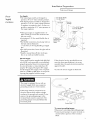
DoorHingeRoller
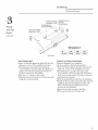
Before moving the range indoors:
• Remove outer carton and packing
from the shipping
base.
material
(Closed}
Remove
_/
• Open
KickPanel
• Remove the kick panel by removing
at the top and pulling forward.
range
To simplify handling
of the range:
• Remove
the grates
knobs.
back.
and to reduce
and drawers
• Remove grill and griddle
ATTEMPT
TO REMOVE
GRIDDLE
Remove
bolts and
fully and hold
down.
and
the
out of" the frame.
RangeMust
beUniformly
Supported
on Braces
left RearShipping
Screws
flange of the range
"L" brackets.
the door
• Close the brass hinge latches to locked
position
on each side.
• Carefully,
lift and pull the door away from
2 screws
The range is secured
m the skid with 2 bolts
the front and 2 "L" brackets
on the bottom
oven doors:
in
Due to the weight of these ranges, use a dolly
with soft wheels to move this range.
• Lift the range onto the dolly and move
indoors.
the weight
below
the
covers. DO NOT
A GRILL OR
ASSEMBLY
• Remove
the broiler pans/literature
from inside oven (s).
package
8
Installation
Pr@ssional
Ranges
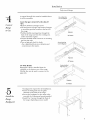
36" and 48" Wide Models:
Pu¢_ilove
Packaging
(continued)
Level the
Range
• Remove the panel from the rear of the
shipping pack. Lay the panel on the floor
directly in front of the installation location.
The range should be placed on this panel to
prevent damage to the floor.
All Models:
• Remove the two strips fi'om the oven
interior: Place the strips on the floor at
lef} and right sides of the installation
location. These strips provide a surface
sliding the range into the final position
will prevent damage to the floor. The
leveling legs must rest permanently on
runner strips.
the
for
and
these
Note: Rear range leveling legs are not accessible af}er installation.
• Acliust the height of the range to countertop
height or higher:
• Check to be sure the aclioining cabinets/
countertops are level, fi'ont to back and lef}
to right across the opening of the range.
• Measure the distance fi'om the floor to the
IMPORTANT:
The range should always be
installed
at countertop
height or highetz DO
NOT INSTALL THE RANGE LOWER THAN
top of the countertop
real- corners.
in the left and right
ADJACENT
COUNTERTOP
HEIGHT.
All Ranges must have an anti-tip device
correctly installed according to these
instructions.
Install
• All RangesCan Tip
Anti-Tip
Device
• Injury CouldResult
• Install Anti-Tip
Bracket Provided
• See Instructions
• If the range is pulled out fi'om the wall for
any reason, make sure that the device is
properly engaged when pushed back against
the wall or installation position.
• If the anti-tip device is not engaged, there is
a possible risk that the range can tip over
and cause injury if you or a child stand, sit or
lean on an open door:
[41#10 x 2" wood screws
The anti-tip bracket is designed to be installed
on top of the slide (runners) provided with
the range. Any other type of construction
may
require special installation techniques to
insure adequate fastening of the anti-tip
bracket to the floor or wall.
• The bracket must be properly installed to
prevent tipping of the range.
• Read the AItAM Anti-Tip Safizty brochure
packed with the product.
Anti-Tip £racket
SafetyBrocMre
AHAMAnti-Tip
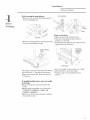
Installation
Pro/essional
Ranges
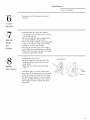
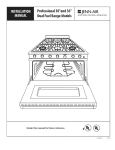
Small HoleForWood (2}Wood Screwsinto
Installations(2Total) BackWall
(All Installations)
(2)LargeHolesFor
\
ConcreteInstallations
Install
Sack
Wall
Small HolesForWood
installations(2 Total)\
Anti-Tip
Device
(continued)
Wood
J
Slide __
Strip
Dimension
A=dels[V'o
112"
ZDP48
A
5/8"
ZDP36
1/4"
ZDP30
\Dimension A
Wood
Construction:
Concrete
• Place the bracket
against the back wall, into the
right rear corner
of the installation
location.
• See Dimension
A, position
the bracket the
correct distance
from the right side. Mark the 2
small screw holes for fastening
the bracket
to
the floor and remove the bracket.
• Drill two, 1/8" diameter
pilot holes.
• Fasten the bracket
securely to the floor
using all 4 screws provided.
and wall
or Cement
Construction:
Hardware
Required
(not supplied):
[2] sleeve anchors, lag bolts and washers.
• Place the bracket against the back wall, into the
right rear corner of the installation
location.
• See Dimension
A, position
the bracket
the
correct
distance from the right side. Mark the 2
large holes for fastening
the bracket
to the floor
and remove the bracket.
• Drill recommended
size holes for the hardware.
• Install the sleeve anchors
into the holes and then
install the lag bolts through
the bracket.
The
bolts must be properly
tightened
as recommended
for the hardware.
• Fasten the bracket
• Drive wood screws
securely
to the floor.
into the back wall.
10
Installation
Pro/essional
A manual shut-offvalve
it will be accessible.
must
be installed
where
Ranges
Flexor RigidGas
gul_
Assure that gas is turned off at the shut-off
valve.
Connect
• Remove all burner/hanger
screws.
• Lift and remove all open top burners/hangers
to reveal the gas inlet location at the back of
the range.
• Pull the flexible metal gas line through the
back of the range and into the cooking area
until it meets the regular.
• Connect flexible metal connector to incoming
gas line pipe stub.
• Turn on gas and check for leaks:
-Use a liquid leak detector at all joints and
connections in the system.
Range
to Gas
\
Regulator
36"Models
Flexor RigidGas
LineToRegulat_
Regulator
48" Models
30" Wide Models:
Rigid pipe is factory installed from the
regulator
to the bottom rear of'the range.
Flexible line may be used to connect
to the
pipe stub.
FactoryInstalled
RigidGasLine
Regulator
30"Models
Install
the
Range
A backguard is required for all installations.
• Insert the backguard into the guide
channels on the back of the range.
• Secure the backguard to the range at the
rear with the 4 sheetmetal screw's provided.
• Install 2 or 3 screws through the front of
the range, depending on your model.
Backguard
11
Installation
Pro/essional
Plug power
receptacle.
cord
into properly
Ranges
grounded
Connect
Electrical
st°
7
Slide the
Range
Into
Position
Replace
• Carefully, slide the range into position.
-Be careful not to entange
power cord and
gas flexible tubing.
• Be sure the right rear leg is engaged
in the
slot of the installed
anti-tip bracket.
• Check for proper
installation
by grasping
the
range at the top fi'ont edge and carefully
attempt
to tilt the range forward.
• Check to be sure the fi'ont of the range is
level. Adjust front leveling legs accordingly.
• Replace the fi'ont kick panel by reversing
the
proceedure
described
in Step 1.
To replace the oven doors:
• Slide the hinges into the openings.
The
hinge should rest in the center of each
hinge roller.
• Open the door fully and unlock hinge
latches.
Oven Door(s)
CAUTION:
Take care when replacing
the
oven doors. If the hinge latch is not securely
locked, the hinge may snap back and separate. If the hinge separates,
you must apply
pressure
(possibly with your foot) to press it
back together
and then engage
the brass
hinge latch.
DoorHingeRoller
-Lock
(Closed)
-Un-Lock
12
Installation
Pr@ssional
9
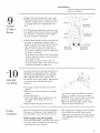
Assemble
& Adjust
Burners
• Replace the burner bowls and burner caps.
• Adjustments should not be required, unless
vibration during transit or variations in local
gas supply make minor adjustments necessary.
Burner-
Ranges
_,__M Igniter
ain Burner
",
CAUTION: Burner adjustments must be made
by a qualified technician at the time of installation. Extreme care should be used if adjustments are made after installation.
• Burner
flames
should
be blue
and stable
IgniterBurner
enturi{rear)
'
'\
SimmerBurner
Ventud{rear)
i_
AirShutter
with
no yellow or yellow tips, excessive noise or
lifting of the flame from the burner.
If any of
these conditions
exist, check
that the air
Main Burner
VentuB{front)
shutter
or burner
ports are not blocked.
If
one of these conditions
continues,
adjust the
air shutter
as required.
-If the flame is too yellow, there is insufficient
air flow, acliust the shutter
counterclockwise
to increase
air inlet.
"SimmerBurner
Venturi{front)
-If the flame is noisy or tends to lift away
from the burner,
there is too much air. Turn
the shutter
clockwise
to reduce air.
Adjustable
Low Setting
The open top burners and grill valves have an
adjustable low setting. Each valve is individually tested and adjusted before it is shipped.
Minor adjustments may be required due to
fluctuations in local gas pressure. Adjustments
to increase or decrease gas flow may be
necessary.
• Turn knob countm_clockwise
to the LITE
position.
• Once lit, turn the know back to the "LOW"
position.
• Remove the knob.
• Insert a thin-blade flat screwdriver into the
valve shaft. (3/32" blade with recommended.)
• Grip the shaft with pliers and turn the
kTnalize
Installation
screwdriver counter-clockwise
to lower the
flame, or clockwise to increase the flame.
CAUTION: Do not turn the flame so low that
it goes out, causing the igniter to spark.
• When the desired setting is made, replace
the knob and turn burner off.
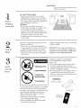
Place the burner grates into operating position.
Press corner of the grate to the cooktop. The
grates should be seated and should not rock.
Models equipped
with grill and griddle:
• The grill and griddle are secured with screws
the front. They are designed
to be stationary
and should not to be removed.
• The griddle has two leveling screws beneath
the rear flue cover which can be used to
adiust to the desired slope. The center screw
is for shipping purposes only and should be
removed.
at
13
Notes
Pro[essional
Ranges
14
Notes
Pro[essional
Ranges
15
NOTE: While perfolming installations describedin this book,
safety glasses or gogglesshould beworn
Q
Monogram:
General Electric Company
Louisville, KY40225
NOTE:
Pioduct
E]ect_i_
The_
_u6}eet
implovement
_t<>] e, mate_
t_ _:hange
without
is a colltlltIlilt,_
_aI_, a}_pearal_:e
no_i,e
endeax
and
ol
at Ge_lel
sl_e_ itleati_
fls aJ e
a]
Pub.No.49_8814-4
]
Dwg.No. 164D3333P058J
(N.D286} 10/01
10658 Rev 6