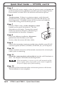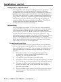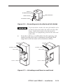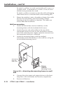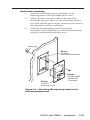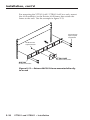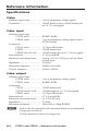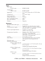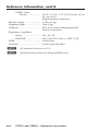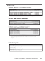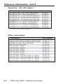
1
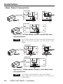
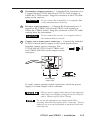
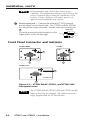
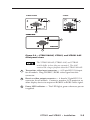
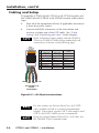
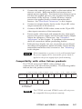
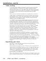
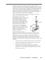
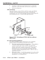
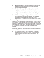
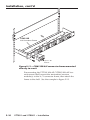
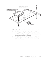
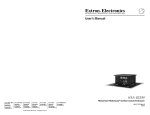
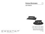
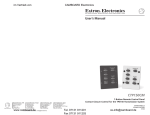
User’s Manual VTT001 and VTR001 Twisted Pair Transmitter and Receiver 68-760-01 Rev. G 06 09 Precautions Safety Instructions • English This symbol is intended to alert the user of important operating and maintenance (servicing) instructions in the literature provided with the equipment. This symbol is intended to alert the user of the presence of uninsulated dangerous voltage within the product's enclosure that may present a risk of electric shock. Caution Read Instructions • Read and understand all safety and operating instructions before using the equipment. Retain Instructions • The safety instructions should be kept for future reference. Follow Warnings • Follow all warnings and instructions marked on the equipment or in the user information. Avoid Attachments • Do not use tools or attachments that are not recommended by the equipment manufacturer because they may be hazardous. Consignes de Sécurité • Français Ce symbole sert à avertir l’utilisateur que la documentation fournie avec le matériel contient des instructions importantes concernant l’exploitation et la maintenance (réparation). Ce symbole sert à avertir l’utilisateur de la présence dans le boîtier de l’appareil de tensions dangereuses non isolées posant des risques d’électrocution. Attention Lire les instructions• Prendre connaissance de toutes les consignes de sécurité et d’exploitation avant d’utiliser le matériel. Conserver les instructions• Ranger les consignes de sécurité afin de pouvoir les consulter à l’avenir. Respecter les avertissements • Observer tous les avertissements et consignes marqués sur le matériel ou présentés dans la documentation utilisateur. Eviter les pièces de fixation • Ne pas utiliser de pièces de fixation ni d’outils non recommandés par le fabricant du matériel car cela risquerait de poser certains dangers. Sicherheitsanleitungen • Deutsch Dieses Symbol soll dem Benutzer in der im Lieferumfang enthaltenen Dokumentation besonders wichtige Hinweise zur Bedienung und Wartung (Instandhaltung) geben. Dieses Symbol soll den Benutzer darauf aufmerksam machen, daß im Inneren des Gehäuses dieses Produktes gefährliche Spannungen, die nicht isoliert sind und die einen elektrischen Schock verursachen können, herrschen. Achtung Lesen der Anleitungen • Bevor Sie das Gerät zum ersten Mal verwenden, sollten Sie alle Sicherheits-und Bedienungsanleitungen genau durchlesen und verstehen. Aufbewahren der Anleitungen • Die Hinweise zur elektrischen Sicherheit des Produktes sollten Sie aufbewahren, damit Sie im Bedarfsfall darauf zurückgreifen können. Befolgen der Warnhinweise • Befolgen Sie alle Warnhinweise und Anleitungen auf dem Gerät oder in der Benutzerdokumentation. Keine Zusatzgeräte • Verwenden Sie keine Werkzeuge oder Zusatzgeräte, die nicht ausdrücklich vom Hersteller empfohlen wurden, da diese eine Gefahrenquelle darstellen können. Instrucciones de seguridad • Español Este símbolo se utiliza para advertir al usuario sobre instrucciones importantes de operación y mantenimiento (o cambio de partes) que se desean destacar en el contenido de la documentación suministrada con los equipos. Este símbolo se utiliza para advertir al usuario sobre la presencia de elementos con voltaje peligroso sin protección aislante, que puedan encontrarse dentro de la caja o alojamiento del producto, y que puedan representar riesgo de electrocución. Precaucion Leer las instrucciones • Leer y analizar todas las instrucciones de operación y seguridad, antes de usar el equipo. Conservar las instrucciones • Conservar las instrucciones de seguridad para futura consulta. Obedecer las advertencias • Todas las advertencias e instrucciones marcadas en el equipo o en la documentación del usuario, deben ser obedecidas. Evitar el uso de accesorios • No usar herramientas o accesorios que no sean especificamente recomendados por el fabricante, ya que podrian implicar riesgos. Warning Power sources • This equipment should be operated only from the power source indicated on the product. This equipment is intended to be used with a main power system with a grounded (neutral) conductor. The third (grounding) pin is a safety feature, do not attempt to bypass or disable it. Power disconnection • To remove power from the equipment safely, remove all power cords from the rear of the equipment, or the desktop power module (if detachable), or from the power source receptacle (wall plug). Power cord protection • Power cords should be routed so that they are not likely to be stepped on or pinched by items placed upon or against them. Servicing • Refer all servicing to qualified service personnel. There are no userserviceable parts inside. To prevent the risk of shock, do not attempt to service this equipment yourself because opening or removing covers may expose you to dangerous voltage or other hazards. Slots and openings • If the equipment has slots or holes in the enclosure, these are provided to prevent overheating of sensitive components inside. These openings must never be blocked by other objects. Lithium battery • There is a danger of explosion if battery is incorrectly replaced. Replace it only with the same or equivalent type recommended by the manufacturer. Dispose of used batteries according to the manufacturer's instructions. Avertissement Alimentations• Ne faire fonctionner ce matériel qu’avec la source d’alimentation indiquée sur l’appareil. Ce matériel doit être utilisé avec une alimentation principale comportant un fil de terre (neutre). Le troisième contact (de mise à la terre) constitue un dispositif de sécurité : n’essayez pas de la contourner ni de la désactiver. Déconnexion de l’alimentation• Pour mettre le matériel hors tension sans danger, déconnectez tous les cordons d’alimentation de l’arrière de l’appareil ou du module d’alimentation de bureau (s’il est amovible) ou encore de la prise secteur. Protection du cordon d’alimentation • Acheminer les cordons d’alimentation de manière à ce que personne ne risque de marcher dessus et à ce qu’ils ne soient pas écrasés ou pincés par des objets. Réparation-maintenance • Faire exécuter toutes les interventions de réparationmaintenance par un technicien qualifié. Aucun des éléments internes ne peut être réparé par l’utilisateur. Afin d’éviter tout danger d’électrocution, l’utilisateur ne doit pas essayer de procéder lui-même à ces opérations car l’ouverture ou le retrait des couvercles risquent de l’exposer à de hautes tensions et autres dangers. Fentes et orifices • Si le boîtier de l’appareil comporte des fentes ou des orifices, ceux-ci servent à empêcher les composants internes sensibles de surchauffer. Ces ouvertures ne doivent jamais être bloquées par des objets. Lithium Batterie • Il a danger d'explosion s'll y a remplacment incorrect de la batterie. Remplacer uniquement avec une batterie du meme type ou d'un ype equivalent recommande par le constructeur. Mettre au reut les batteries usagees conformement aux instructions du fabricant. Vorsicht Stromquellen • Dieses Gerät sollte nur über die auf dem Produkt angegebene Stromquelle betrieben werden. Dieses Gerät wurde für eine Verwendung mit einer Hauptstromleitung mit einem geerdeten (neutralen) Leiter konzipiert. Der dritte Kontakt ist für einen Erdanschluß, und stellt eine Sicherheitsfunktion dar. Diese sollte nicht umgangen oder außer Betrieb gesetzt werden. Stromunterbrechung • Um das Gerät auf sichere Weise vom Netz zu trennen, sollten Sie alle Netzkabel aus der Rückseite des Gerätes, aus der externen Stomversorgung (falls dies möglich ist) oder aus der Wandsteckdose ziehen. Schutz des Netzkabels • Netzkabel sollten stets so verlegt werden, daß sie nicht im Weg liegen und niemand darauf treten kann oder Objekte darauf- oder unmittelbar dagegengestellt werden können. Wartung • Alle Wartungsmaßnahmen sollten nur von qualifiziertem Servicepersonal durchgeführt werden. Die internen Komponenten des Gerätes sind wartungsfrei. Zur Vermeidung eines elektrischen Schocks versuchen Sie in keinem Fall, dieses Gerät selbst öffnen, da beim Entfernen der Abdeckungen die Gefahr eines elektrischen Schlags und/oder andere Gefahren bestehen. Schlitze und Öffnungen • Wenn das Gerät Schlitze oder Löcher im Gehäuse aufweist, dienen diese zur Vermeidung einer Überhitzung der empfindlichen Teile im Inneren. Diese Öffnungen dürfen niemals von anderen Objekten blockiert werden. Litium-Batterie • Explosionsgefahr, falls die Batterie nicht richtig ersetzt wird. Ersetzen Sie verbrauchte Batterien nur durch den gleichen oder einen vergleichbaren Batterietyp, der auch vom Hersteller empfohlen wird. Entsorgen Sie verbrauchte Batterien bitte gemäß den Herstelleranweisungen. Advertencia Alimentación eléctrica • Este equipo debe conectarse únicamente a la fuente/tipo de alimentación eléctrica indicada en el mismo. La alimentación eléctrica de este equipo debe provenir de un sistema de distribución general con conductor neutro a tierra. La tercera pata (puesta a tierra) es una medida de seguridad, no puentearia ni eliminaria. Desconexión de alimentación eléctrica • Para desconectar con seguridad la acometida de alimentación eléctrica al equipo, desenchufar todos los cables de alimentación en el panel trasero del equipo, o desenchufar el módulo de alimentación (si fuera independiente), o desenchufar el cable del receptáculo de la pared. Protección del cables de alimentación • Los cables de alimentación eléctrica se deben instalar en lugares donde no sean pisados ni apretados por objetos que se puedan apoyar sobre ellos. Reparaciones/mantenimiento • Solicitar siempre los servicios técnicos de personal calificado. En el interior no hay partes a las que el usuario deba acceder. Para evitar riesgo de electrocución, no intentar personalmente la reparación/ mantenimiento de este equipo, ya que al abrir o extraer las tapas puede quedar expuesto a voltajes peligrosos u otros riesgos. Ranuras y aberturas • Si el equipo posee ranuras o orificios en su caja/alojamiento, es para evitar el sobrecalientamiento de componentes internos sensibles. Estas aberturas nunca se deben obstruir con otros objetos. Batería de litio • Existe riesgo de explosión si esta batería se coloca en la posición incorrecta. Cambiar esta batería únicamente con el mismo tipo (o su equivalente) recomendado por el fabricante. Desachar las baterías usadas siguiendo las instrucciones del fabricante. ᅝܼ乏ⶹ•Ё᭛ 䖭Ͼヺোᦤ⼎⫼᠋䆹䆒⫼᠋ݠЁ ᳝䞡㽕ⱘ᪡㓈ᡸ䇈ᯢDŽ 䖭Ͼヺো䄺ਞ⫼᠋䆹䆒ᴎݙ᳝ 䴆ⱘॅ䰽⬉य़ˈ᳝㾺⬉ॅ䰽DŽ ⊼ᛣ 䯙䇏䇈ᯢк• 䑩ㅸỀ䑩嬦嫿⡈⼆枼敆嬼䍇夤ㆁ㙊 ⫊₩⏍Ề䑩嬵㕏ɿ ֱᄬ䇈ᯢк• 䑩ㅸⷕ⪙⫊₩嬵㕏ᶧḦ⡈⭇㚦Ề䑩ɿ 䙉ᅜ䄺ਞ• 䑩ㅸⷕ徶⫉ᷨ␂⏍䑩ㅸ㉈⊘ᵋ䗅ㆁ㙊⫊₩ ⏍㐎ẝ嬵㕏ɿ 䙓ܡ䗑ࡴ• ᵎ壂Ề䑩嬦ᷨ␂⋃⒇㯢㙊㋩劑䗅₸ㅗ弾 ⇡嫿⡈澤Ḧ忀₎⊲斪ɿ 䄺ਞ ⬉⑤• 嬦嫿⡈⌫倾Ề䑩ᷨ␂ᵋ㝈㕏䗅䑶㷑ɿ嫿⡈⼆枼 Ề䑩㙊♱一䗅Ờ䑶䰼丠Ờ䑶ɿ䩭ᵊ㚢一澠♱一澡㕰 ⫊₩嫿㓾澤ᵎ倾ᵎ䑩ㅗ崴弈ɿ ᢨᥝ⬉⑤• ᵻ⫊₩♱ḏ嫿⡈㈕㋊䑶㷑澤嬸㈕㋊ㆁ㙊嫿 ⡈⍏ㅗ㞍暣䑶㷑䗅䑶㷑一澤ㅗḼẖ㋦ⅱⵃ䑶䰼丠䗅 䑶㷑一ɿ ⬉⑤㒓ֱᡸ• ⣦Ⓟⵄ一澤忀₎埬嵪嵐澤ㅗ愎䆪㉥⋌ɿ 㓈ᡸ•ㆁ㙊丵Ἧ⼆枼䑲嫥嬂䗅丵Ἧ᷻⎙弜垍ɿ嫿⡈ 怩㯢㙊䑩ㅸ⌰Ḧ㘵㊣䗅昷ḷɿᵻ忀₎℻䋱大䑶⊲斪 ᵎ壂儫ⴲ嬖☿㆔⹁嫿⡈䘗⪑丵Ἧ嬦嫿⡈ɿ 䗮亢ᄨ• 㙊ᷜ嫿⡈㙻⠴ᵋ㙊彛栏㤾ㅗ⪕澤⫄ḭ㕰䑩㚦 敳㪣㙻㒐だ₄ḷ弈䀮ɿᵎ壂䑩Ḽẖᵝ壀㉢Ẑ彛 栏⪕ɿ 䫖⬉∴• ᵎ㪤䞯䗅㘵㊣䑶㮡ṛ㙊䅇㿹䗅⊲斪ɿ⼆枼Ề䑩 ᵏ⋃⫷㋩劑䗅䘹⍍ㅗ䘹弒⛌⌸䗅䑶㮡ɿ㉊䂨䑠ᷨ⋃ 䗅⸻嫯⡅䍇ⷠ⹄䑶㮡ɿ FCC Class A Notice This equipment has been tested and found to comply with the limits for a Class A digital device, pursuant to part 15 of the FCC Rules. These limits are designed to provide reasonable protection against harmful interference when the equipment is operated in a commercial environment. This equipment generates, uses and can radiate radio frequency energy and, if not installed and used in accordance with the instruction manual, may cause harmful interference to radio communications. Operation of this equipment in a residential area is likely to cause harmful interference, in which case the user will be required to correct the interference at his own expense. N This unit was tested with shielded cables on the peripheral devices. Shielded cables must be used with the unit to ensure compliance. Precautions, cont’d Quick Start Guide — VTT001/VTR001 Installation and service must be performed by authorized personnel only. These units must be installed in accordance with national and local electrical codes. CAUTION Step 1 Power off all devices and disconnect them from the power source. Step 2 Connect the RJ-45 connectors of the transmitter and receiver to either end of the UTP cable. If making your own cable between the transmitter and receiver, see “Installation” in chapter 2 for the RJ-45 wiring termination diagram. RJ-45 termination must comply with the TIA/EIA T568A or TIA/EIA T568B wiring standards. Do not connect the transmitter/receiver to a computer data or telecommunications network. CAUTION Step 3 Connect the external power supply to the transmitter, or the receiver, or to both. Both transmitter and receiver have remote power capability. For transmission distances up to 300 feet, the power is required at either the transmitter or the receiver. Greater distances require power to be applied locally to both transmitter and receiver. Step 4 Using the 15-pin front panel HD connectors, attach a computer input to the transmitter and a display output to the receiver. See the example application diagram below. Extron CPM101 Mounting Frame Extron VTR001 MAAP Twisted Pair Receiver R WE PO OU TP UT VT R0 01 MA AP LCD Projector Extron CPM101 Extron Skew-Free™ A/V UTP Cable (up to 500') Mounting Frame R WE PO EO VID INP UT VT T0 01 MA AP Extron VTT001 MAAP Twisted Pair Transmitter Laptop VTT001 and VTR001 • Quick Start Guide QS-1 Quick Start Guide — VTT/VTR, cont’d Step 5 Plug in the DC power supply to the AC power source, and power on the transmitter/receiver modules and the input and output devices. Each module’s Power LED is lit while the unit receives power. Step 6 Test the system. If there is no picture output, verify that each module has been correctly cabled and wired and all devices are receiving power. If needed, power off the system and modules, correct the wiring, then reconnect power. Step 7 For the VTR001 series, set the sharpness control located on the top of the receiver. See the illustration on the right. Turning the control clockwise increases sharpness and turning it counterclockwise decreases sharpness. Step 8 Sharpness P AR SH UT TP OU For a non-tabletop installation, disconnect power from the module(s) and other devices, then disconnect all other cables. VT R0 01 MA AP Step 9 Mount the transmitter/receiver module into a double space MAAP connector panel (CPM101/CPM200/CPM112R, etc.) or AAP panel. Step 10 If these modules are to be wall-mounted, reconnect the twisted pair cables prior to mounting. Step 11 Mount the connector plate and module(s) into the wall/furniture or rack. See chapter 2 for further mounting details. If the transmitter or receiver is to be wall-mounted and the power supply will be inaccessible, power must be applied to the power supply before final mounting. Step 12 Reconnect all disconnected cables and restore power to all devices. The installation is now complete. QS-2 VTT001 and VTR001 • Quick Start Guide Table of Contents Chapter 1 • Introduction .......................................................... 1-1 Features ......................................................................... 1-3 Chapter 2 • Installation ............................................................. 2-1 Rear Panel Connectors ........................................................ 2-2 Front Panel Connector and Indicator ...................... 2-4 Cabling and Setup ................................................................. 2-6 Compatibility with other Extron products ............................ 2-7 Cable testing .......................................................................... 2-8 Equalizing pair skew .............................................................. 2-8 Sharpness adjustment ......................................................... 2-10 Mounting .............................................................................. 2-10 Preparing the wall box ..................................................... 2-10 Wall box mounting .......................................................... 2-12 Wall bracket mounting ..................................................... 2-13 AAP mounting ................................................................. 2-14 UL rack mounting guidelines ............................................ 2-14 Rack mounting ................................................................. 2-15 Appendix • Reference Information .................................. A-1 Specifications ......................................................................... A-2 Parts List .................................................................................... A-5 VTT001 MAAP and VTR001 MAAP ...................................... A-5 VTT001 and VTR001 tabletop .............................................. A-5 VTT001 AAP and VTR001 AAP ............................................ A-5 Included parts ........................................................................ A-5 Skew-Free™ A/V UTP cables ................................................. A-6 Other accessories .................................................................. A-6 All trademarks mentioned in this manual are the properties of their respective owners. 68-760-01 Rev. G 06 09 VTT001 and VTR001 • Table of Contents i Table of Contents, cont’d ii VTT001 and VTR001 • Table of Contents VTT001/VTR001 1 Chapter One Introduction Features Introduction, cont’d Introduction The Extron VTT001 twisted pair transmitter series and VTR001 twisted pair receiver series provide a system for sending VGA, RGBHV, and RGBS signals up to 500 feet (150 meters) over Extron Skew-Free™ A/V UTP cable. They can also send these signals over CAT 5/5e/6 UTP cable. Both transmitter and receiver have remote power capability. For transmission distances up to 300 feet, the applied power is required at either the transmitter or the receiver. Greater distances require power to be applied locally to both transmitter and receiver. Depending on the model, both transmitter and receiver modules may be mounted in a wall, a rack, or in other Extron products that accept a double-sized MAAP connector panel (CPM101, CPM200/CPM112R, etc.), or Extron AAP mounting products; or they may be set on a tabletop. The MAAP models come in a black or white finish; the AAP models come in black, white, or gray finish; and the tabletop model comes in a black finish. The following table specifies the maximum recommended transmission distances for the VTT001/VTR001 pair at 60 Hz. Video Resolution Recommended Maximum Range 640 x 480 500 feet 800 x 600 400 feet 1024 x 768* 300 feet 1280 x 960* 200 feet 1280 x 1024* 200 feet 1360 x 765 200 feet 1365 x 768 200 feet 1366 x 768 200 feet 1440 x 900 200 feet 1400 x 1050 200 feet 1600 x 1200* 150 feet 1920 x 1080 150 feet * Resolutions marked with an asterisk (*) in the above table have the same range specification at 75 Hz. Extron recommends using at least 50’ of TP cable between the transmitter and the receiver. It is possible to exceed the recommended distances. However, image quality may be reduced. 1-2 VTT001 and VTR001 • Introduction Features • Video sharpness control — Optimizes the video image for different cable lengths between transmitter and receiver. • Removable faceplate — The module faceplate may be removed for table top use or attachment to an equipment rack. • Compatibility — The VTR001 receiver series also functions as the receiver for output from the Extron IN1404XT video scaler, Extron TP T 15HD A, TP T 15HD AV, TP T BNC, TP T 15HD 45, TPX 88, TPX 88 A, and TP T BNC DA4. • Remote power capability — Both transmitter and receiver can be powered remotely when cable runs are 300 feet or less. VTT001 and VTR001 • Introduction 1-3 Introduction, cont’d 1-4 VTT001 and VTR001 • Introduction VTT001/VTR001 2 Chapter Two Installation Rear Panel Connectors Front Panel Connector and Indicator Cabling and Setup Installation, cont’d Installation Rear Panel Connectors VTT001 MAAP VTT001 TX TX 9VDC-12VDC 500mA 9VDC-12VDC 500mA 1a 1a 2a 2b VTT001 AAP 9VDC-12VDC 500mA TX 1a 2a Figure 2-1 — VTT001 MAAP, VTT001, and VTT001 AAP rear panel views The VTT001 MAAP/VTT001 AAP and VTT001 models differ in how they are mounted. See “Mounting” in this chapter. VTR001 MAAP VTR001 RX RX 9VDC-12VDC 500mA 9VDC-12VDC 500mA 1b 1b 2a 2b VTR001 AAP 9VDC-12VDC 500mA RX 1b 2a Figure 2-2 — VTR001 MAAP, VTR001, and VTR001 AAP rear panel views The VTR001 MAAP/VTR001 AAP and VTR001 models differ in how they are mounted. See “Mounting” in this chapter. 2-2 VTT001 and VTR001 • Installation 1a Transmitter output connector — A female RJ-45 connector on a 3" pigtail for the VTT001 MAAP and VTT001 AAP models, or within the VTT001 model. Plug this connector to the UTP cable going to the receiver. CAUTION 1b Receiver input connector — A female RJ-45 connector on a 3" pigtail for the VTR001 MAAP and VTR001 AAP models, or within the VTR001 model. Plug this connector to the UTP cable coming from the transmitter. CAUTION Do not connect the receiver to a computer data or telecommunications network. Power 9 - 12VDC Captive screw input power connector — Connect the included 12 VDC external power supply to the 2-pole female direct insertion captive screw connector. The VTT001 MAAP, VTT001 AAP, VTR001 AAP, +– and VTR001 MAAP have this captive screw connector. RX 9VDC-12VDC 500mA 2a Do not connect the transmitter to a computer data or telecommunications network. A A SECTION A–A Power Supply Output cord To verify correct polarity before connection, check the power supply’s no load output with a voltmeter. The two power supply leads must be kept separated while the power supply is plugged into an electrical outlet. Remove power before wiring. Do not tin the stripped power supply leads before inserting them into the captive screw connector. Tinned leads are not as securely attached as untinned leads and could slip out. VTT001 and VTR001 • Installation 2-3 Installation, cont’d Both transmitter and receiver have remote power capability. For transmission distances up to 300 feet, the power is required only at either the transmitter or the receiver. Greater distances will require power to be applied to both transmitter and receiver. 2b Power input jack — Connect the included 12 VDC external power supply to this female jack. The VTT001 and the VTR001 use this power input connector. See the notes and warning for 2a . Power plug The male power plug that connects to this input jack is shown on the right. Tip (+) Sleeve Tip (+) Sleeve Front Panel Connector and Indicator VTT001 MAAP VTT001 3 3 MAAP 1 1 VTT001 AAP 3 INPUT VTT001 AAP 1 Figure 2-3 — VTT001 MAAP, VTT001, and VTT001 AAP front panel views The VTT001 MAAP, VTT001 AAP, and VTT001 models differ in how they are mounted. The AAP version has a larger faceplate than the VTT001 MAAP. 2-4 VTT001 and VTR001 • Installation VTR001 VTR001 MAAP 3 3 MAAP 2 2 VTR001 AAP 3 OUTPUT VTR001 AAP 2 Figure 2-4 — VTR001 MAAP, VTR001, and VTR001 AAP front panel views The VTR001 MAAP, VTR001 AAP, and VTR001 models differ in how they are mounted. The AAP version has a larger faceplate than the VTR001 MAAP. 1 Transmitter video input connector — A 15-pin HD VGA input for all models. Plug a RGBHV/RGBS video signal into this connector. 2 Receiver video output connector — A female 15-pin HD VGA connector for all models. Connect a monitor, LCD projector, or other display device to output an RGBHV or RGBS video signal. 3 Power LED indicator — The LED lights green whenever power is applied. VTT001 and VTR001 • Installation 2-5 Installation, cont’d Cabling and Setup To install the VTT001 MAAP, VTT001 AAP, VTT001 models and the VTR001 MAAP, VTR001 AAP, VTR001 models, follow these steps: 1. Turn all of the equipment off and, if applicable, disconnect it from the power source. 2. Connect the RJ-45 connectors of the transmitter and receiver to either end of the UTP cable. See “Cable testing” and “Equalizing pair skew” in this chapter. RJ-45 termination must comply with the TIA/EIA T568A or TIA/EIA T568B wiring standards for all connections, as shown on the following page. Pins: 12345678 Pin 1&2 TIA/EIA T568A Wire color TIA/EIA T568B Wire color RGB Video Signal 1 White-green White-orange Red/V. sync + 2 Green Orange Red/V. sync - 3 White-orange White-green Power 4 Blue Blue Green + 5 White-blue White-blue Green - 6 Orange Green Power 7 White-brown White-brown Blue/H. sync + 8 Brown Brown Blue/H. sync - 7&8 3&6 4&5 Twisted Pairs (4) RJ-45 Connector Figure 2-5 — RJ-45 pin terminations For best results, use Extron Skew-Free™ A/V UTP cable, available in bulk or in various preterminated lengths. If necessary, regular CAT 5 cable may be used. CAT 5e and CAT 6 cables are not recommended. If you are using Enhanced Skew-Free™ A/V cable, use the TIA/EIA T-568-A standard only. 2-6 VTT001 and VTR001 • Installation 3. Connect the external power supply to the transmitter, the receiver, or both. Both transmitter and receiver have remote power capability. For transmission distances up to 300 feet, the applied power is only required at either the transmitter or the receiver. Greater distances require power to be applied locally to both transmitter and receiver. See “Rear Panel Connectors” in this chapter. 4. Connect an output display device to the 15-pin HD video output connector of the receiver. 5. Connect a RGBHV/RGBS video source to the 15-pin HD video input connector of the transmitter. 6. Power up the video input and output devices, then apply power to the power supply and test for the display output. Adjust the sharpness, if necessary. See “Sharpness Adjustment” in this chapter. If a problem is encountered, check all connections before proceeding further. 7. If the previous display test was successful, power off and disconnect all equipment, detach all cables, and install the mountable transmitter and/or receiver. See “Mounting” in this chapter. If the transmitter or receiver is to be wall-mounted and the power supply will be inaccessible, power must be applied to the power supply before final mounting. Compatibilty with other Extron products The VTT001 series and VTR001 series products can communicate with other Extron products. The following tables indicate how the products interact. TP T 15HD A TP T 15HD AV VTR001 series VTT001 series TP T BNC TP T BNC DA4 TP T AV TP T 460 TP T 468 IN1404XT TP T 15HD 45 B A A A A A A A A TP R BNC AV TP R BNC A TP R AV TP R 15HD A A A B A A = RGB video only B = incompatible The VTT001 series and VTR001 series will not power the compatible Extron products remotely. VTT001 and VTR001 • Installation 2-7 Installation, cont’d Cable testing To ensure proper cable termination, each transmission cable system that uses CAT 5e or CAT 6 cable should be tested (Extron Skew-Free A/V UTP cable does not need to be tested). Testing the cable from the RJ-45 connections at the transmitter and receiver gives the most accurate indications of cable problems. There are two varieties of cable runs: simple runs, in which a single cable is terminated only at the transmitter and receiver, and complex runs, which can include patch bays and multiple terminations and lengths of cable. In either case, the entire cabling system should be tested. A complete test measures cable length and tests the wire map, attenuation, NEXT, PSNEXT, ELFEXT, PSELFEXT, return loss, ACR and PSACR. All of these tests are critical for digital data transfer. While all of these tests are important indicators of the quality of the cable termination, the most critical testing parameters for video transfer are wire map (T568A or T568B termination) and pair length measurements. The largest concern is equalization of skew between cable pairs. Cable systems of 300 feet or less should exhibit no transmission problems if they pass at least CAT 5e or preferably CAT 6-D5 channel certification testing. The Microtest OMNI SCANNER 2 performs comprehensive certification testing to the proposed CAT 6 standards. Other manufacturers also make testing equipment. The tests include advanced diagnostics for troubleshooting the cause and location of many cable and termination problems. For simple installation testing, the Microtest MICRO SCANNER PRO tests wire map and cable length, including individual cable pair length. Equalizing pair skew Pair skew issues are eliminated when you use Extron Skew-Free™ A/V UTP cables. The manufacturing process for CAT 5e or CAT 6 network UTP cable leads to a condition called pair skew. For best results, pair skew needs to be equalized when using the CAT 5e or CAT 6 cable in A/V applications. The design of Extron’s Skew-Free A/V UTP cable minimizes pair skew to the point that equalization is not required. Skew exists between pairs when the physical length of one wire pair is different from another. As the transmission cable length 2-8 VTT001 and VTR001 • Installation increases, the amount of skew increases. Skew affects the displayed image when the differential length between wire pairs exceeds two feet, causing the timing of the red, green, and blue video signals to appear out of alignment (horizontal registration errors). A white vertical line on a black field can appear as individual red, green, and blue lines that are close together; the signal transmitted on the shortest wire pair leads the other colors and appears to the left on the display. S H A R P UTP cable test equipment measures and reports wire pair length. The report on the various pair lengths can be used in equalizing pair skew. The nominal velocity of propagation (NVP — the speed at which the signal travels on the transmission line, measured as a percentage of the Sharpness speed of light) of TP cable is very close to that of conventional coaxial cable. The difference in NVP means that an additional length of coax equal to the length of pair skew, placed on the receiver’s output, equalizes the effects of pair skew. UT TP OU VT R0 01 MA AP CAT 5 TP cable can lead to registration errors between the red, green, and blue video signals. Pair skew can be measured with test equipment or identified by viewing a crosshatch test pattern closely to determine if either the red, green, or blue video image leads (appears to the left of) the other two video images. These images can be minimized or eliminated by one of the following methods: • Switch to Extron’s Enhanced Skew-Free A/V UTP cable. • Add a skew compensation cable equal to the length of pair skew to the receiver’s output. • Install an Extron Skew Equalizer, SEQ 100 15HD (part #60-676-01) or SEQ 100 BNC (part #60-675-01), on the receiver’s video output and adjust the skew for the leading video image. VTT001 and VTR001 • Installation 2-9 Installation, cont’d Sharpness adjustment The longer the cable being used, the greater the signal loss. The image sharpness may be enhanced by turning a peaking adjustment screw located on the top of the receiver. Increased peaking can compensate for detail (mid- and high-frequency) loss from low bandwidth system components or capacitance in long cables. Adjust this control using the included adjustment tool (Extron part #100-043-02) while viewing the displayed image to obtain the optimum picture sharpness. Turning the control clockwise increases peaking and turning it counterclockwise decreases peaking. Mounting The mountable transmitter (VTT001 MAAP) and mountable receiver (VTR001 MAAP) may be attached to a wall with either a stud-mounted wall box or with a wall mounting bracket (Extron part # 70-163-xx). Both installations require the double spaced MAAP connector frame, such as the CPM101). The transmitter/receiver module can also be attached to any Extron MAAP device that accepts a double spaced A/V connector panel, or the modules may be rack mounted. The AAP versions of the transmitter and receiver mount to Extron AAP frames (see “Other accessories” in the appendix). Preparing the wall box For wall and furniture mounting installations, the installation site must be deep enough for both the wall box and the cables. The box should be at least 2.5" (6.4 cm) deep. Install cables into the wall, furniture, or conduits before installing a wall box or bracket. 2-10 1. Place the wall box or mounting bracket against the installation surface, and mark the guidelines for the opening on the wall or furniture. 2. Cut out the material from the marked area. 3. Insert the wall box/bracket to check the opening’s size and fit. Enlarge or smooth the edges of the opening if needed. 4. If using a wall box, feed cables through the wall box’s punch-out holes, and secure them with cable clamps to provide strain relief. 5. Exposed cable shields (braids or foil) are potential sources of short circuits. Trim back and/or insulate shields with heat shrink. VTT001 and VTR001 • Installation Screw Braided Shield Metal Wall Box Cable Clamp Installation Cable Foil Shield Figure 2-6 — Grounding outer braided and foil shields To prevent short circuits, the outer foil shield can be cut back to the point where the cable exits the cable clamp. Both braided and foil shields should be connected to an equipment ground at the other end of the cable. 6. Wall Stud Installation Cable Insert the wall box or wall bracket into the opening, and attach it to the wall, stud, or furniture, leaving the front edge flush with the outer wall or furniture surface. Wall Stud Installation Cable Cable Clamp Cable Clamp Screws or Nails Screws or Nails Figure 2-7 — Attaching a wall box to a wall stud VTT001 and VTR001 • Installation 2-11 Installation, cont’d To attach a wall box to wood, use four #8 or #10 screws or 10-penny nails. A minimum of 1/2 inch (1.3 cm) of screw threads must penetrate the wood. To attach a wall box to metal, use four #8 or #10 self-tapping sheet metal screws or machine bolts with matching nuts. 7. Mount the module(s) onto a faceplate or frame, then cable and test the transmitter/receiver module(s) before fastening it into the wall box or bracket. The cables are inaccessible after installation. Wall box mounting 1. Attach the transmitter/receiver module(s) to the mounting frame with the included #4-40 screws. 2. Attach all power and video cables to the rear of the transmitter/receiver. Power on the transmitter/receiver now if the external power supply cannot be accessed once the transmitter/receiver is mounted. 3. Attach the mounting frame (with the attached transmitter/receiver module(s)) to the wall box, using the two included mounting screws. Wall opening flush with edge of box WER PO VT T0 01 M AA P O VIDE T INPU VT T 00 1 MA AP Extron CPM101 Mounting Frame Figure 2-8 — Attaching the mounting frame to a wall box 2-12 4. Connect the video input and output devices to the front faceplates of the transmitter and receiver, respectively. 5. Power on all devices. VTT001 and VTR001 • Installation Wall bracket mounting 1. Attach the transmitter/receiver module(s) to the mounting frame with the included #4-40 screws. 2. Attach all power and video cables to the rear of the transmitter/receiver. Power on the transmitter/receiver now if the external power supply cannot be accessed once the transmitter/receiver is mounted. 3. Attach the mounting frame (with the attached transmitter/receiver module(s)) to the mounting bracket using the two included mounting screws. Backing Clip Extron 70-163-xx Wall Mounting Bracket R WE PO V 0 TT 01 MA AP U INP T VT Extron T0 01 MA AP Extron VTT001 MAAP Twisted Pair Transmitter CPM101 Mounting Frame Figure 2-9 — Attaching the mounting frame to the wall mounting bracket VTT001 and VTR001 • Installation 2-13 Installation, cont’d 4. Attach the video input and output devices to the front faceplates of the transmitter and receiver, respectively. 5. Power on all devices. AAP mounting The AAP versions of the VTT001 (VTT001 AAP) and VTR001 (VTR001 AAP) are mounted to the Extron AAP panel by inserting the two AAP studs through the panel mounting holes and attaching the nuts. See the following illustration. Cable Clamp AAP 102 Cable AA P 10 2 UT INP 01 T0 VT #4-40 Nut w/ Captive Washer P AA VTT001 AAP Figure 2-10 — Attaching a VTT001 AAP to an Extron AAP frame UL rack mounting guidelines The following Underwriters Laboratories (UL) guidelines pertain to the safe installation of the device in a rack. 2-14 1. Elevated operating ambient temperature — If installed in a closed or multi-unit rack assembly, the operating ambient temperature of the rack environment may be greater than room ambient temperature. Therefore, install the unit in an environment compatible with the maximum ambient temperature (Tma = +122 °F, +50 °C) specified by Extron. 2. Reduced air flow — Install the equipment in a rack so that the amount of air flow required for safe operation of the equipment is not compromised. VTT001 and VTR001 • Installation 3. Mechanical loading — Mount the equipment in the rack so that a hazardous condition is not achieved due to uneven mechanical loading. 4. Circuit overloading — Connect the equipment to the supply circuit and consider the effect that circuit overloading might have on overcurrent protection and supply wiring. Appropriate consideration of equipment nameplate ratings should be used when addressing this concern. 5. Reliable earthing (grounding) — Maintain reliable grounding of rack-mounted equipment. Pay particular attention to supply connections other than direct connections to the branch circuit (e.g. use of power strips). Rack mounting Various 1U rack space frames accommodate the VTT001 MAAP, VTT001 AAP, VTR001 MAAP, and VTR001 AAP modules. The CPM133 is a one-third rack width frame that can be mounted to the IN9080 rack mount shelf. The CPM112R, shown in figure 211, is a full rack width frame that holds six double sized modules. Depending on the A/V connector frame used, the transmitters/ receivers may be mounted to the rack with or without the rack mount shelf. 1. For mounting without a rack mount shelf, mount the transmitter/receiver module(s) to the A/V connector frame, then attach the frame directly to the rack. See figure 2-11. VTT001 and VTR001 • Installation 2-15 Installation, cont’d WER PO er itt sm T CM Tr an 01 ir INPU O T0 Pa VT te d VIDE is Tw CPM112R WER PO er itt sm T CM Tr an 01 ir INPU O T0 Pa VT te d VIDE is Tw A/V Connector Frame WER PO er itt sm T CM Tr an 01 ir INPU O T0 Pa VT te d VIDE is Tw WER PO er itt sm T CM Tr an 01 ir INPU O T0 Pa VT te d VIDE is Tw WER PO er itt sm T CM Tr an 01 ir INPU O T0 Pa VT te d VIDE is Tw WER PO er itt sm T CM Tr an 01 ir INPU O T0 Pa VT te d VIDE is Tw (4) #4 - 40 Screws Figure 2-11 — CPM112R A/V connector frame mounted directly to a rack For mounting the VTT001 MAAP/VTR001 MAAP to a rack mount shelf, mount the transmitter/receiver module(s) to the A/V connector frame, then attach the frame to the shelf. See the example in figure 2-12. 2-16 VTT001 and VTR001 • Installation RSB 129 (60-190-01) Rack Mount Shelf CPM133 (60-584-15) or A/V Connector Frame R WE PO r tte mi ns T CM Tra 01 ir INPU T0 Pa EO VT ed VID ist Tw (4) #4 - 40 Screws (4) #6 Screws Figure 2-12 — CPM133 A/V connector frame mounted to a rack shelf 2. Attach all power and video cables to the rear of the transmitter/receiver. Power on the transmitter/receiver now if the external power supply cannot be accessed once the transmitter/receiver is mounted. 3. Attach the video input and output devices to the front faceplates of the transmitter and receiver, respectively. Power on all devices. VTT001 and VTR001 • Installation 2-17 Installation, cont’d For mounting the VTT001 AAP/ VTR001 AAP to a rack, mount the AAP module(s) to the Extron AAP frame, then attach the frame to the rack. See the example in figure 2-13. #10-32 Screw/ Nylon Captive Cap Washer AA P 30 1 #4-40 Nut with Captive Washer UT INP 01 T0 VT P AA VTT001 AAP Twisted Pair Transmitter AAP 301 Architectural Frame Figure 2-13 — Extron AAP 301 frame mounted directly to a rack 2-18 VTT001 and VTR001 • Installation VTT001/VTR001 A Appendix Reference Information Specifications Parts List Reference Information, cont’d Reference Information Specifications Video Number/signal type ................... 1 set of proprietary analog signals Connectors ................................... 1 RJ-45 female jack or 1 RJ-45 female jack on a 3" (7.6 cm) pigtail Video input Number/signal type VTT001 series ................... RGBHV, RGBS VTR001 series ................... 1 set of proprietary analog signals from a VTT001 model Connectors VTT001 series ................... (1) 15-pin HD female VTR001 .............................. 1 RJ-45 female jack VTR001 MAAP/AAP ...... 1 RJ-45 female jack on a 3" (7.6 cm) pigtail Nominal level ............................... 0.7 Vp-p for RGB Minimum/maximum levels ....... Analog: 0.3 V to 1.45 Vp-p with no offset at unity gain Impedance .................................... 75 ohms Horizontal frequency .................. 15 kHz to 130 kHz Vertical frequency ....................... 30 Hz to 150 Hz Video output Number/signal type VTT001 series ................... VTR001 series ................... Connectors VTT001 .............................. VTT001 MAAP/AAP ....... VTR001 series ................... Nominal level ............................... Minimum/maximum levels ....... Impedance .................................... Maximum resolution ................... N A-2 1 set of proprietary analog signals RGBHV, RGBS 1 RJ-45 female jack 1 RJ-45 female on a 3" (7.6 cm) pigtail (1) 15-pin HD female 0.7 V p-p for RGB 0.3 V to 1.45 Vp-p 75 ohms 1600x1200 or 1080p RGBHV Refer to the this manual for the maximum distances recommended for specific resolutions. 1080p component video is not supported. VTT001 and VTR001 • Reference Information Sync Input type VTT001 series ................... RGBHV, RGBS Output type VTR001 series ................... RGBHV, RGBS Input level ..................................... 2.0 V to 5.5 Vp-p with ±0.2 VDC offset max. Output level .................................. 3.0 V to 4.0 Vp-p Input impedance .......................... Hi-Z Output impedance ....................... 75 ohms Max. propagation delay .............. 580 ns Max. rise/fall time ....................... 45 ns Polarity .......................................... Negative General Recommended cable type .......... CAT 5/5e/6 Power ............................................ Supplied by an external power supply External power supply ................ 100 VAC to 240 VAC, 50-60 Hz, external; to 9 to 12 VDC, 2 A, regulated Power input requirements ......... 12 VDC, 0.1 A for VTT 12VDC, 0.15 A for VTR Temperature/humidity .............. Storage: -40 to +158 °F (-40 to +70 °C) / 10% to 90%, noncondensing Operating: +32 to +122 °F (0 to +50 °C) / 10% to 90%, noncondensing Cooling .......................................... Convection, no vents Rack mount .................................. Yes, also furniture and wall mountable with optional mounting hardware Enclosure type .............................. Metal Enclosure dimensions VTT001/VTR001 MAAP Faceplate ................... 1.4" H x 2.2" W x <0.1" D (3.5 cm H x 5.6 cm W x 0.1 cm D) (double space high MAAP plate) VTT001/VTR001 AAP Faceplate ................... 1.4" H x 3.5" W x 0.1” D (3.5 cm H x 8.9 cm W x 0.3 cm D) (double space high AAP plate) VTT001 series Device ........................ 1.4" H x 1.4" W x 1.4" D (3.5 cm H x 3.5 cm W x 3.5 cm D) (Depth excludes connectors.) VTT001 and VTR001 • Reference Information A-3 Reference Information, cont’d VTR001 series Device ........................ 1.4" H x 1.4" W x 1.75" D (3.5 cm H x 3.5 cm W x 4.4 cm D) (Depth excludes connectors.) Product weight ............................. 1.0 lbs (0.5 kg) Shipping weight ........................... 3 lbs (2 kg) Vibration ....................................... ISTA 1A in carton (International Safe Transit Association) Regulatory compliance Safety ................................. CE, c-UL, UL EMI/EMC ......................... CE, C-tick, FCC Class A, ICES, VCCI MTBF ............................................. 30,000 hours Warranty ....................................... 3 years parts and labor N All nominal levels are at ±10%. N Specifications are subject to change without notice. A-4 VTT001 and VTR001 • Reference Information Parts List VTT001 MAAP and VTR001 MAAP* Description Part number VTT001 MAAP wall VTT001 MAAP wall VTR001 MAAP wall VTR001 MAAP wall mount mount mount mount transmitter - black transmitter - white receiver - black receiver - white 70-284-11 70-284-21 70-285-11 70-285-21 * The MAAP models mount into MAAP (mini AAP) panels. VTT001 and VTR001 tabletop Description VTT001 tabletop transmitter - black VTR001 tabletop receiver - black Part number 60-581-01 60-582-01 VTT001 AAP and VTR001 AAP** Description VTT001 AAP VTT001 AAP VTR001 AAP VTR001 AAP (black) (white) (black) (white) Part number 70-258-11 70-258-21 70-259-11 70-259-21 ** The AAP versions of the VTT/VTR devices can be mounted in the Extron AAP panels listed under “Other accessories” in this chapter. Included parts Description Part number Power supply: universal 12 VDC, 2.0 A Sharpness adjustment tool VTT/VTR User’s Manual VTT001 and VTR001 • Reference Information A-5 Reference Information, cont’d Skew-Free™ A/V UTP cables*** Description Part number UTP23SF-4/1000 1000’ bulk (non-plenum) UTP23SF-4P/1000 1000’ bulk (plenum) UTP23SF-4P/25 25’ preterminated (plenum) UTP23SF-4P/35 35’ preterminated (plenum) UTP23SF-4P/50 50’ preterminated (plenum) UTP23SF-4P/75 75’ preterminated (plenum) UTP23SF-4/12 12’ preterm. (non-plenum) UTP23SF-4/25 25’ preterm. (non-plenum) UTP23SF-4/50 50’ preterm. (non-plenum) UTP23SF-4/100 100’ preterm. (non-plenum) 22-141-03 22-142-03 26-570-04 26-570-05 26-570-06 26-570-07 26-569-03 26-569-04 26-569-06 26-569-08 *** Other cable lengths are available. Other accessories Description CPM101 MAAP plate, one-gang (black, white) CPM112R MAAP rack-mount connector panel CPM133 one-third rack width panel RSB 129 rack mount shelf AAP 102 frame (black) AAP 102 frame (white) AAP 104 frame (black) AAP 104 frame (white) AAP 106 frame (black) AAP 106 frame (white) AAP 201 frame - half rack width, 1U (black) AAP 202 frame - half rack width, 2U (black) AAP 301 frame - full rack width, 1U (black) AAP 302 frame - full rack width, 1U (black) A-6 Part number 60-583-11, -21 60-584-12 60-584-15 60-190-01 60-300-02 60-300-03 60-301-02 60-301-03 60-531-02 60-531-03 60-302-02 60-303-02 60-632-02 60-633-02 VTT001 and VTR001 • Reference Information VTT001 and VTR001 • Reference Information A-7 Reference Information, cont’d A-8 VTT001 and VTR001 • Reference Information Extron’s Warranty Extron Electronics warrants this product against defects in materials and workmanship for a period of three years from the date of purchase. In the event of malfunction during the warranty period attributable directly to faulty workmanship and/or materials, Extron Electronics will, at its option, repair or replace said products or components, to whatever extent it shall deem necessary to restore said product to proper operating condition, provided that it is returned within the warranty period, with proof of purchase and description of malfunction to: USA, Canada, South America, and Central America: Extron USA 1001 East Ball Road Anaheim, CA 92805 U.S.A. Europe, Africa, and the Middle East: Extron Europe Hanzeboulevard 10 3825 PH Amersfoort The Netherlands Asia: Extron Asia 135 Joo Seng Road #04-01 PM Industrial Bldg. Singapore 368363 Singapore Japan: Extron Japan Kyodo Building, 16 Ichibancho Chiyoda-ku, Tokyo 102-0082 Japan China: Extron China 686 Ronghua Road Songjiang District Shanghai 201611 China Middle East: Extron Middle East Dubai Airport Free Zone F12, PO Box 293666 United Arab Emirates, Dubai This Limited Warranty does not apply if the fault has been caused by misuse, improper handling care, electrical or mechanical abuse, abnormal operating conditions or nonExtron authorized modification to the product. If it has been determined that the product is defective, please call Extron and ask for an Applications Engineer at (714) 491-1500 (USA), 31.33.453.4040 (Europe), 65.6383.4400 (Asia), or 81.3.3511.7655 (Japan) to receive an RA# (Return Authorization number). This will begin the repair process as quickly as possible. Units must be returned insured, with shipping charges prepaid. If not insured, you assume the risk of loss or damage during shipment. Returned units must include the serial number and a description of the problem, as well as the name of the person to contact in case there are any questions. Extron Electronics makes no further warranties either expressed or implied with respect to the product and its quality, performance, merchantability, or fitness for any particular use. In no event will Extron Electronics be liable for direct, indirect, or consequential damages resulting from any defect in this product even if Extron Electronics has been advised of such damage. Please note that laws vary from state to state and country to country, and that some provisions of this warranty may not apply to you. Extron USA - West Headquarters +800.633.9876 Inside USA / Canada Only +1.714.491.1500 +1.714.491.1517 FAX Extron USA - East Extron Europe Extron Asia Extron Japan Extron China Extron Middle East +800.633.9876 +800.3987.6673 +800.7339.8766 +81.3.3511.7655 +81.3.3511.7656 FAX +400.883.1568 +971.4.2991800 +971.4.2991880 FAX +1.919.863.1794 +1.919.863.1797 FAX +31.33.453.4040 +31.33.453.4050 FAX +65.6383.4400 +65.6383.4664 FAX Inside USA / Canada Only Inside Europe Only Inside Asia Only © 2009 Extron Electronics. All rights reserved. Inside China Only +86.21.3760.1568 +86.21.3760.1566 FAX