1
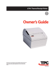
THERMAL PRINTING SOLUTIONS
APOS PREMIUM PRINTER SERIES
USER MANUAL
Reference 3107312 Issue A
August 2004
AXIOHM
1, rue d'Arcueil, BP 820
92542 MONTROUGE CEDEX
FRANCE
Tel : (33) 1 58 07 17 17, Fax : (33) 1 58 07 17 18
www.axiohm.biz
EVOLUTIONS
Date
07/02
06/03
07/03
08/04
Issue
Preliminary 1
Preliminary 2
Z
A
Modifications
Creation
Added USB connection and easy font command
APOS Premium Printer Series User Manual
Page 1 /136
Reference: FDE 3107312 Issue A
CONTENTS
1
GENERAL DESCRIPTION ................................................................. 5
2
SPECIFICATIONS................................................................................ 6
2.1
Physical specification .............................................................................. 6
2.1.1
Dimensions ............................................................................... 6
2.2
Print head specification .......................................................................... 6
2.2.1
Power supply ............................................................................ 6
2.3
Environmental specifications ................................................................. 7
2.3.1
Environmental conditions......................................................... 7
2.3.2
EMI and Safety standards applied ............................................ 7
2.4
Operational performance ....................................................................... 8
2.4.1
Paper specification.................................................................... 8
2.4.2
Speed ........................................................................................ 8
2.4.3
Lifetime .................................................................................... 8
2.5
Characters ............................................................................................... 9
2.5.1
Print Modes............................................................................... 9
2.5.2
Size ........................................................................................... 9
2.5.3
Print zone................................................................................ 10
2.5.4
Resident font dimensions........................................................ 11
2.5.5
Print density and density of receipt print lines ....................... 12
2.5.6
Printing duty cycle (printing solid blocks) ............................. 12
2.5.7
Character sets.......................................................................... 13
2.5.7.1 Code Page 437......................................................................................13
2.5.7.2 Code Page 850......................................................................................14
2.5.7.3 Code Page 852......................................................................................15
2.5.7.4 Code Page 858......................................................................................16
2.5.7.5 Code Page 860......................................................................................17
2.5.7.6 Code Page 862......................................................................................18
2.5.7.7 Code Page 863......................................................................................19
2.5.7.8 Code Page 865......................................................................................20
2.5.7.9 Code Page 866......................................................................................21
2.5.7.10 Code Page 1252..................................................................................22
3
WARRANTY ........................................................................................ 23
4
YOUR PRINTER ................................................................................. 24
4.1
Getting ready to use the printer........................................................... 24
4.1.1
Unpacking the printer ............................................................. 24
4.1.2
Description of printer parts..................................................... 24
4.1.3
Buttons.................................................................................... 24
4.1.4
LED Indicator ......................................................................... 24
4.1.5
Cutter ...................................................................................... 25
4.1.6
Connectors .............................................................................. 25
4.1.7
Cable traps .............................................................................. 25
4.1.8
Mounting holes ....................................................................... 25
4.1.9
Sensors.................................................................................... 25
APOS Premium Printer Series User Manual
Page 2 /136
Reference: FDE 3107312 Issue A
4.2
Choosing the proper location for your printer................................... 26
4.3
Loading paper ....................................................................................... 26
4.4
Light indicator....................................................................................... 26
4.5
Connectors & cables ............................................................................. 26
4.5.1
Power connector ..................................................................... 27
4.5.2
Communications interface connectors.................................... 27
4.5.2.1 RS232 Connector..................................................................................27
4.5.2.2 USB Connector.....................................................................................28
4.5.2.3 Drawer kick-out connector ...................................................................28
4.6
Communication Interface Control ...................................................... 29
4.6.1
RS232 ..................................................................................... 29
4.6.1.1 XON/XOFF Protocol............................................................................29
4.6.1.2 DTR/DSR Protocol...............................................................................29
4.6.2
USB PARAMETERS ............................................................. 30
4.6.2.1
4.6.2.2
4.6.2.3
4.6.2.4
Capabilities ..........................................................................................30
Connector.............................................................................................30
Interface ...............................................................................................30
Other information ................................................................................30
4.7
Self test description ............................................................................... 31
4.8
Configuration menu.............................................................................. 33
4.8.1
How to enter ........................................................................... 33
4.8.2
How to adjust parameters ....................................................... 33
4.8.3
How to quit ............................................................................. 33
4.8.4
List of parameters that can be changed................................... 34
5
LIST OF CONTROL CODES ............................................................ 35
6
COMMAND DESCRIPTION ............................................................. 39
6.1
Command Conventions ........................................................................ 39
6.2
Reset commands.................................................................................... 40
6.3
Paper Cut commands............................................................................ 41
6.4
Sensor commands.................................................................................. 43
6.5
Vertical Positioning and Print Commands ......................................... 44
6.6
Horizontal Positioning Commands...................................................... 49
6.7
Printer configuration ............................................................................ 54
6.8
Print Characteristics Commands ........................................................ 55
6.9
Font commands ..................................................................................... 63
6.10 Graphics Commands ............................................................................ 69
6.11 Logo commands .................................................................................... 73
6.12 Printer Status Commands .................................................................... 77
6.13 Real Time Commands .......................................................................... 91
6.14 Bar Code Commands............................................................................ 97
6.15 Page Mode Commands ....................................................................... 100
6.16 Macro Commands............................................................................... 107
6.17 Drawer kick-out & internal buzzer Commands............................... 108
APOS Premium Printer Series User Manual
Page 3 /136
Reference: FDE 3107312 Issue A
6.18 Flash Firmware Download Commands ............................................ 109
6.19 Boot Download .................................................................................... 114
6.20 User Flash Memory Commands ........................................................ 115
6.21 User Data Storage Commands........................................................... 117
6.22 Peripheral control commands............................................................ 117
6.23 Transaction Monitoring Commands ................................................. 118
6.24 Easy Font Support .............................................................................. 120
6.25 Configuration commands ................................................................... 125
7
TROUBLESHOOTING..................................................................... 133
7.1
Light indicator..................................................................................... 133
7.2
Problems & Solutions ......................................................................... 133
7.2.1
Printer Problems ................................................................... 133
7.2.2
LED Problems ...................................................................... 133
7.2.3
Printing Problems ................................................................. 134
8
CLEANING YOUR PRINTER......................................................... 135
9
SPARES ............................................................................................ 136
APOS Premium Printer Series User Manual
Page 4 /136
Reference: FDE 3107312 Issue A
1
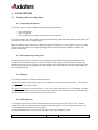
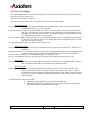
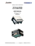
GENERAL DESCRIPTION
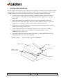
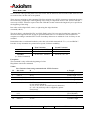
This set-up guide describes how to set up and operate the high-speed, thermal, point-of-sale (POS) printer
manufactured by Axiohm SAS. The printer has many features, which give advantages to retailers, and is
versatile enough to be used in other applications such as for printing out tickets and coupons.
Axiohm’s unique and patented paper-loading mechanism makes this printer the easiest-touse POS printer on the market. The fixed-head thermal printer engine gives a very high
quality print.
An untrained operator can change the roll of paper quickly and reliably, minimizing
downtimes and avoiding paper jams. There are no messy ribbons to change, so good print
quality can be ‘designed-in’ without operator skills or regular maintenance.
The printer uses thick-film technology to achieve the longest-life cutter with the optional
patented semi-rotating ceramic cutter.
As part of the total ‘easy-to-use’ philosophy, the printer uses a super-set of industrystandard software to allow for easy installation. The existing software needs no
modification and is ready to use.
The APOS printer will accurately print many barcodes, it allows custom characters to be
downloaded and it can execute macro functions.
Interfaces offered:
RS232 & USB for greatest compatibility
Opening cover
On / Off
Paper feed
Finger recess
to open cover
Paper exit
APOS Premium Printer Series User Manual
Page 5 /136
Reference: FDE 3107312 Issue A
2
SPECIFICATIONS
2.1 Physical specification
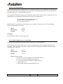
2.1.1 Dimensions
115mm
170mm
205mm
1390 g
Height
Width
Depth
Weight (with cutter)
2.2 Print head specification
The APOS printer uses a fixed-head thermal print head, using thick-film techniques to ensure the highest
performance.
Print head type
Printing width:
Number of dots across width:
Resolution (dot-density):
Thermal line
72 mm
576
8 dots / mm
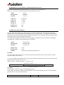
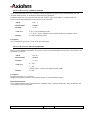
2.2.1 Power supply
The printer requires a power supply of 24V at 2,2A minimum.
Other voltages, which are required internally for the micro controller and the communications ports, are
generated internally from the 24V supply.
Specification:
Output voltage:
Output current:
24 VDC (no load)
2.20 A mean continuously
14 A peak during 500 µs max (pulse cycle = 1ms)
The power supply should be a “SELV” type in order to meet safety standards.
APOS Premium Printer Series User Manual
Page 6 /136
Reference: FDE 3107312 Issue A
2.3 Environmental specifications
2.3.1 Environmental conditions
Operating temperature:
Storage temperature:
Maximum humidity:
+0°C - +50°C
-40°C - +85°C
90% RH (non-condensing)
2.3.2 EMI and Safety standards applied
The printer is designed to meet the following requirements:
Europe
CE Marking:
Safety Standards:
EN 60950
North America
EMI: FCC Part 15 class A
Safety standard UL60950, CAN/CSA C22.2 60950
Conditions of acceptability
EMI is measured using Axiohm power supply adapter ref. 3107329
The printer is to be powered by a SELV circuit only
The communication connectors must be of SELV type only
Safety recommendations
The power supply should be installed so it can be accessed to enable power disconnection.
APOS Premium Printer Series User Manual
Page 7 /136
Reference: FDE 3107312 Issue A
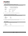
2.4 Operational performance
2.4.1
Paper specification
Paper width
Maximum paper roll diameter
(Maximum paper roll length)
Recommended papers
Emulsion (sensitive) side
80mm
83mm
82m (using 60gsm paper)
AXIOHM ref 3101123
KANZAKI P350
On outside of roll
* You must contact Axiohm if you wish to use an alternative type of paper; otherwise your warranty might
not be valid and you could cause damage to your printer.
2.4.2
Speed
The printer is capable of printing at a maximum speed of 130mm/s with 20% of the dots on, provided that
sufficient power supply current is available (See section 2.1.3 about power supply requirements).
The actual speed can also be affected by the data rate at which information is sent to the printer over the
communication link. Sending large amounts of graphic data could reduce the actual speed.
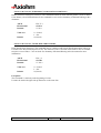
2.4.3
Lifetime
The printer lifetime depends on the actual operating conditions and is defined by the MTBF of the
electronics and the wear characteristics of the electromechanical parts. The actual lifetime will therefore be
the minimum of the following three categories, depending on the particular application:
•
•
•
Electronic MTBF of 220,000 hrs of powered use
100km of paper used by the printer (with typically 20% of the dots heated)
Two million cuts from the ceramic cutter mechanism.
APOS Premium Printer Series User Manual
Page 8 /136
Reference: FDE 3107312 Issue A
2.5 Characters
2.5.1 Print Modes
♦
♦
♦
♦
♦
♦
♦
♦
♦
♦
♦
♦
Available print modes:
Standard
Compressed
Double High
Double Wide
Upside Down
Rotated
Underlined
Bold
Reverse
Italic
Scaled
2.5.2 Size
Characters sizes for the Standard and Compressed modes:
Standard
♦
♦
♦
Characters per Inch: 15.6
Characters per Line: 44
Cell Size: 13 x 24 Dots
Compressed
♦
♦
♦
Characters per Inch: 20.3
Characters per Line: 56
Cell Size: 10 x 24 Dots
APOS Premium Printer Series User Manual
Page 9 /136
Reference: FDE 3107312 Issue A
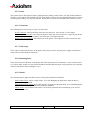
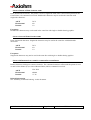
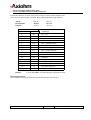
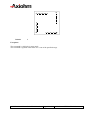
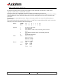
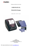
2.5.3 Print zone
576 dots (addressable) @ 8 dots/mm, centered on 80 mm
Standard Mode: minimum margins: 2.5 mm (.098 inches)
Top margin to knife cut: 17.8 mm (0.70 inches)
Paper Width = 80 mm (3.15 in.)
Printable Zone, 576 Dots = 72 mm (2.835 in.)
Nominal Margins, 4 mm (0.157 in.)
Cut Edge
Cut Edge
Top Margin, 17.8 mm (.70 in.) Minimum
44 Standard Columns = 71.5 mm (2.815 in.)
56 Compressed Columns = 70 mm (2.756 in.)
APOS Premium Printer Series User Manual
Page 10 /136
Reference: FDE 3107312 Issue A
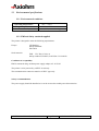
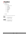
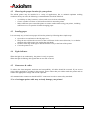
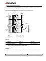
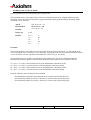
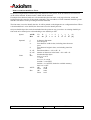
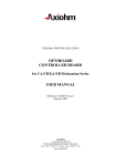
2.5.4 Resident font dimensions
10 x 24 Font
13 x 24 Font
APOS Premium Printer Series User Manual
Page 11 /136
Reference: FDE 3107312 Issue A
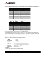
2.5.5 Print density and density of receipt print lines
This function makes it possible to adjust the energy level of the print head to darken the printout. An
adjustment should only be made when necessary. The factory setting is 100%.
Warning:
Choose an energy level no higher than necessary to achieve a dark printout.
Failure to observe this rule may result in a printer service call or voiding of the printer warranty.
Consult your Axiohm technical support specialist if you have any questions.
When printing lines at high dot coverage (text or graphics), the printer automatically slows down to limit
power consumption below power supply setting (60W, 75W, 90W).
To change the Print Density:
a)
Enter the Configuration Menu.
b)
Select “Set Hardware Options” from Main Menu.
“Hardware Options Menu” is printed on the receipt and the question “Set Print Density?” asked.
c)
Answer YES (Long click).
A warning is printed, followed by:
Print Density
80%
90%
100%
110%
120%
1 Click
2 Clicks
3 Clicks
4 Clicks
5 Clicks
Enter code, then hold Button DOWN at least 1 second to validate.
2.5.6 Printing duty cycle (printing solid blocks)
In order to guarantee the lifetime of the printer and meet safety standards, receipt printing should not
exceed a 40 % of the duty cycle (for example 2 sec print, 3 sec pause)
APOS Premium Printer Series User Manual
Page 12 /136
Reference: FDE 3107312 Issue A
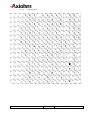
2.5.7 Character sets
2.5.7.1
Code Page 437
APOS Premium Printer Series User Manual
Page 13 /136
Reference: FDE 3107312 Issue A
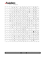
2.5.7.2
Code Page 850
APOS Premium Printer Series User Manual
Page 14 /136
Reference: FDE 3107312 Issue A
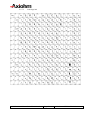
2.5.7.3
Code Page 852
APOS Premium Printer Series User Manual
Page 15 /136
Reference: FDE 3107312 Issue A
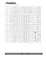
2.5.7.4
Code Page 858
APOS Premium Printer Series User Manual
Page 16 /136
Reference: FDE 3107312 Issue A
2.5.7.5
Code Page 860
APOS Premium Printer Series User Manual
Page 17 /136
Reference: FDE 3107312 Issue A
2.5.7.6
Code Page 862
APOS Premium Printer Series User Manual
Page 18 /136
Reference: FDE 3107312 Issue A
2.5.7.7
Code Page 863
APOS Premium Printer Series User Manual
Page 19 /136
Reference: FDE 3107312 Issue A
2.5.7.8
Code Page 865
APOS Premium Printer Series User Manual
Page 20 /136
Reference: FDE 3107312 Issue A
2.5.7.9
Code Page 866
APOS Premium Printer Series User Manual
Page 21 /136
Reference: FDE 3107312 Issue A
2.5.7.10
Code Page 1252
APOS Premium Printer Series User Manual
Page 22 /136
Reference: FDE 3107312 Issue A
3
WARRANTY
The printers or spare parts are guaranteed for a standard period of one (1) year, beginning at the delivery
date (ex-works).
AXIOHM can set specific warranty terms for any Customer asking for warranty extension or other services
concerning the warranty process.
The printers are guaranteed against defective material and/or workmanship. The warranty covers only, and
at AXIOHM’s choice, the cost of repair or replacement by AXIOHM in its factory, after restitution by the
customer of the printers or spare parts confirmed by AXIOHM to be defective (excluding assembling,
dismounting, shipping and other expenses).
The implementation of the warranty will not extend the warranty period.
Due to the complexity of the electronic and mechanical techniques used in the operation of such a printer,
AXIOHM does not warranty problems resulting from an installation not according to the published
specifications.
This warranty is subject to strict compliance with AXIOHM’s technical instructions for installation, use
and maintenance.
In particular, this warranty will not be valid for any defects due to:
Use of thermal paper other than those recommended by AXIOHM.
Incorrect maintenance.
Defective installation or modification not approved by AXIOHM.
Non-compliance, during any period, with the specified working conditions including the
electrical power supply specifications.
Abnormal wear or mechanical damage, including dot burning due to power overloads.
Transportation in packaging other than the type of carton / foam insert in which the printer was
originally packed.
Any transportation, storage or setting up which does not comply with the technical specifications given to
the customer by AXIOHM, or its official distributor, will invalidate this warranty.
In no event shall AXIOHM assume any liability in excess of that defined above. It is agreed that AXIOHM
will not be liable for any indemnity for accidents to persons, damage to property or for loss of earnings.
APOS Premium Printer Series User Manual
Page 23 /136
Reference: FDE 3107312 Issue A
4
YOUR PRINTER
4.1 Getting ready to use the printer
4.1.1 Unpacking the printer
The printer comes in a plain cardboard carton and separate pockets for:
•
•
•
One APOS printer
One set-up guide
One standard power supply with 24V power lead (optional)
The model number and serial number (including manufacturing week and batch number) of the printer will
be marked on the exterior of the packaging.
Make sure that no parts are missing or damaged. Report any deficiency to your supplier as soon as possible
after receiving the printer. The original packaging material should be kept to transport or return your
printer, if necessary.
4.1.2 Description of printer parts
The APOS printer contains a patented easy-loading printer mechanism designed and manufactured by
Axiohm. This mechanism consists of a main cavity into which a paper roll is dropped for loading. The
thermal print head is in front of this cavity and a rubber roller is attached to the lid of the mechanism. When
the lid is closed, the paper is trapped between the rubber roller and the print head to give close alignment
and consistent pressure.
4.1.3 Buttons
The APOS printer has two buttons on the front panel:
The ON/OFF button is physically connected to the hard reset on the main controller board. Even when it is
OFF, the printer is always powered.
The Paper Feed button’s normal function is to advance paper when the unit is not printing. The button
function may be disabled under software control and it can be used to control the action of a defined macro.
This button also activates a self-test printout (see section 2.7).
4.1.4 LED Indicator
A rectangular green LED is used to indicate the basic status of the printer. The LED is “off” when the
printer is off, and “on” under normal circumstances when the printer is on. It will flash when there is an
“error condition” such as when it is out of paper.
An internal audible buzzer is activated as well when such “error condition” occurs.
APOS Premium Printer Series User Manual
Page 24 /136
Reference: FDE 3107312 Issue A
4.1.5 Cutter
The printer may be fitted with Axiohm’s patented semi-rotating ceramic cutter. It is split with one blade in
the lower cavity and the other fitted to the lid. These blades are also correctly aligned when the lid is closed
to make paper loading very easy and jam-free. Partial cuts or full cuts are possible under software control.
4.1.6 Connectors
The APOS printer can have up to 3 types of connectors:
Power connector: fitted to the base of the unit near the front. (See section 2.5.1 for detail)
Two interfaces connector: one is fitted to the base of the unit closer to the rear; a 9-pin D-type in the
case of serial communication RS232. The other one is an USB connector.
Drawer kick-out connector: fitted at the rear of the printer. These appear as a RJ11 connector. (See
section 2.5.3 for details)
4.1.7 Cable traps
Three clips are fitted into the base of the printer; they may be used to trap the power supply and interface
cables into recessed channels in the base.
4.1.8 Mounting holes
There are two holes in the base of the printer that allow the printer to be attached to a vertical surface such
as a wall or pillar. In this case, the printer should be mounted with the paper exiting from the top so that the
roll does not fall out when opening the cover.
4.1.9 Sensors
The APOS printer is fitted with three sensors, which detect abnormal conditions:
Door-closed sensor: a micro-switch sensor. To avoid damaging the print head, when the door is
open, printing is inhibited.
End-of-paper (EOP) sensor: detects the presence of paper near the print head. To avoid damaging the
print head, when no paper is detected, printing is inhibited.
Cutter sensor: used to detect if the cutter is in its home position before commencing a cut, and on
completion of a cut.
APOS Premium Printer Series User Manual
Page 25 /136
Reference: FDE 3107312 Issue A
4.2 Choosing the proper location for your printer
The APOS printer may be installed in a variety of applications; but, to maintain optimum working
conditions from your unit, the following recommendations should be followed:
•
•
•
Avoid dirty or dusty locations, or those with excessive heat or humidity
Choose a stable level base or solid wall on which to mount the printer
Make sufficient space around the printer to ensure comfort while using your printer, including
sufficient access to open the lid while changing paper.
4.3 Loading paper
It is extremely easy to load a new paper roll into the printer by following these simple steps:
Open the cover and remove the old paper core;
Drop the new roll into the reservoir so that it will rotate in the correct direction (i.e. so that the
emulsion side of the paper rests against the print head)
Hold the front edge of the paper outside the main cavity at the front of the printer
Close the printer cover
4.4 Light indicator
When the light is on continuously, the printer is ready to operate.
When the light is flashing, this signals that an error has occurred.
4.5 Connectors & cables
To reduce the electromagnetic emissions and susceptibility, all cables should be screened. If you are not
using cables supplied by Axiohm for this purpose, please ensure that your cables match the printer and are
rated at the appropriate voltage and current capacities.
All communication connectors should be SELV connectors in order to meet safety standards.
*Use of an inappropriate cable may seriously damage your printer!
APOS Premium Printer Series User Manual
Page 26 /136
Reference: FDE 3107312 Issue A
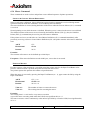
4.5.1 Power connector
The connector is a shielded 6-pin female mini-Din plug.
6
5
4
3
2
Pins 1, 3 &5:
Pins 2, 4 & 6:
Shield:
GND
24V
EARTH
1
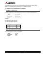
4.5.2 Communications interface connectors
The RS232 interface uses 9-pin D-type male connectors.
4.5.2.1
RS232 Connector
Cable for DTR/DSR protocol
CONNECTOR VIEW
1
2
6
3
7
4
8
male DB9 connector
5
9
N/C
RXD
TXD
DTR
GND
DSR
RTS
CTS
N/C
1:
2:
3:
4:
5:
6:
7:
8:
9:
male DB9 connector
:1
:2
:3
:4
:5
:6
:7
:8
:9
N/C
RXD
TXD
DTR
GND
DSR
RTS
CTS
N/C
Note: RTS/CTS should be tied together if using DOS print commands on a PC station.
APOS Premium Printer Series User Manual
Page 27 /136
Reference: FDE 3107312 Issue A
4.5.2.2
USB Connector
USB
Connector
TYPE B
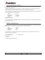
4.5.2.3
Drawer kick-out connector
The connector used to open a cash drawer and monitor, whether the drawer is opened or closed, is a 6-pin
modular RJ11 connector.
CONNECTOR VIEW
PINOUT
1 2 3 4 5 6
1:
2:
3:
4:
5:
6:
PRINTER
Frame ground
Solenoid 1 (-ve)
Switch (+ve)
Solenoid Common (+ve)
Solenoid 2 (-ve)
Switch (-ve)
CASH DRAWER
24V
(1A max)
4
S2
5
S1
2
S2
S1
Drawer-release
solenoids
5V
10k
3
Drawer open /
closed switch
SW
6
1
APOS Premium Printer Series User Manual
Page 28 /136
Reference: FDE 3107312 Issue A
4.6 Communication Interface Control
4.6.1 RS232
The RS-232C interface uses either XON/XOFF (software) or DTR/DSR (hardware) protocol to control the
flow of information between the computer and the printer.
In XON/XOFF mode, a particular character is sent back and forth between the host and the printer to
regulate the communication.
In DTR/DSR mode, changes in the DTR/DSR signal on the RS-232C interface controls the information
flow.
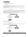
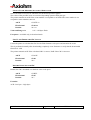
4.6.1.1
XON/XOFF Protocol
The XON/XOFF characters controls the information transfer between the printer and the host computer.
The printer sends an XON character when it is ready to receive data and it sends an XOFF character when
it cannot accept any more data. The software on the host computer must monitor the communication link as
shown in the following flowchart in order to send data at the appropriate times.
If XON/XOFF has been selected, the printer also toggles the DTR signal, as described in the next section,
but it does not look at the DSR signal to transmit data.
Was an XON or
XOFF character
last received ?
XOFF
13 HEX
Wait for XON
character
XON
11 HEX
Send Data
XON character = hexadecimal 11.
XOFF character = hexadecimal 13.
4.6.1.2
DTR/DSR Protocol
The DTR signal is used to control data transmission to the printer. It is driven low when the printer is ready
to receive data and driven high when it cannot accept any more data.
Is DTR
HIGH or LOW
HIGH
Wait for DTR
To go LOW
LOW
Send Data
APOS Premium Printer Series User Manual
Page 29 /136
Reference: FDE 3107312 Issue A
4.6.2 USB PARAMETERS
Axiohm’s implementation of USB complies with “Universal Serial Bus Specification” rev 1.1
4.6.2.1
Capabilities
Apos Premium is a device only, and doesn’t provide hub capabilities.
Full speed communication (12Mbits/sec) is supported.
4.6.2.2
Connector
The connector is located at the rear of the printer, and is specified as B-type
Refer to USB specification rev 1.1 chapter 6 for more information.
4.6.2.3
Interface
The datas are exchanged between host and printer via five endpoints:
Endpoint 0x00 : CONTROL
Default endpoint
Endpoint 0x02 : BULK OUT
For transmission of all printable datas and commands except real time commands, from host to printer
Endpoint 0x83 : BULK IN
For return of all synchronous datas , status or other types of information except unsolicited status mode
messages, from printer to host
Endpoint 0x81 : INTERRUPT IN
For return of asynchronous datas, typically unsolicited status mode messages, from printer to host
Endpoint 0x04 : INTERRUPT OUT
For transmission of real time commands, from host to printer.
4.6.2.4
Other information
- USB V1.1
- Full Speed communication 12 Mbits/sec
- Single USB Connector (Peripheral mode)
Vendor ID:
Axiohm USB Vendor Id = 0x05D9
APOS Premium Printer Series User Manual
Product Id:
APOS PREMIUM product Id = 0xA000
Page 30 /136
Reference: FDE 3107312 Issue A
4.7 Self test description
The self-test ticket can be printed by pressing both Reset and Paper feed button and releasing the Reset
button.
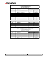
Here is the description of all the lines that you can read when you print a self-test.
Model Number:
This is an 8 digit number fixed by Axiohm.
Serial Number:
This is a 10 digit number fixed by Axiohm.*
*Serial number will be encoded as follows:
First letter:
Next two digits:
Next two digits:
Next 5 digits:
C or D
year of production
week of production
incremental number that is reset every Monday morning.
Example: C or D030906623
=> Board manufactured week 9 of the year 2003, 6623rd product manufactured that week.
Boot Firmware:
Revision
CRC
4 digit revision number fixed by Axiohm.
Boot code CRC.
Flash Firmware:
Revision
CRC
4 digit revision number fixed by Axiohm.
Flash Main code CRC.
Hardware:
Flash Memory Size
Flash Logos/Fonts
Flash User Storage
SRAM Size
CPU Clock Freq.
Max Power
Total size of the flash memory.
Flash memory allocated for logos or user defined fonts.
Flash memory allocated for user data storage (ex: electronic journal).
Total size of the RAM Memory
Microprocessor Clock frequency.
Maximum average power drawn from power supply
Mechanism:
Paper Type
Paper Width
Print Density
Pre-Heating
Max Speed
Knife
Partial Cut
Indicates the reference of the paper used matching with the mechanism.
Indicated the paper width used.
Percentage of the nominal heating time value for specified paper.
This mode is used to maintain print head temperature above 35°c when
enabled.
Printer's top speed.
Enable Knife Operation.
Indicate the number of steps done to perform a partial cut.
APOS Premium Printer Series User Manual
Page 31 /136
Reference: FDE 3107312 Issue A
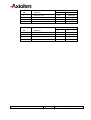
Communication Interface:
RX Buffer Size
Interface Type
Parameters (RS232 only)
Baud Rate
Data Bits
Stop Bit(s)
Parity
Flow Control
Reception Errors
Print Options:
Diagnostics
Default LPI
Carriage Return
Logo(s) defined
User Char(s) defined
This indicates the size of the Receive buffer.
RS232 or USB interface.
Baud rate Value.
Number of data bits
Number of stop bit(s)
Type of parity to control frame validity
Hardware or software handshaking.
Indicates which action is to be done when a wrong data is received.
This line indicates in which mode the board is:
- Off corresponds to normal operation
- Data Scope is used to print data all datas received from the host in
ASCII and HEX format.
Default inter-lines spacing.
Select how to process a 0DH character received from the host.
current status = YES if at least one logo is defined
current status = YES if at least one character is defined
Revision Number:
This is a 10 digit number that can be user defined
Codes Pages:
Default
Resident
Indicates default internal code page selected upon reset.
List of internal codes pages.
User Tallies:
Receipt Lines
Knife Cuts
Hours ON
Flash cycles
Knife Jams
Cover Openings
Max temp reached
Head damaged
Indicates the number of text lines printed.
Indicates the number of cuts performed.
Indicates the number of hours the board has been turned ON.
Indicates the number of flash memory download cycles.
Indicates the number of times that a cutter jam appeared.
Indicates the number of cover opening/closing cycles.
Indicates the maximum temperature (in C degrees) reached by the
print head.
Indicates if the print head is damaged or not.
Note: Tallies are updated every 1 hour or 1000 lines printed, whichever comes first.
APOS Premium Printer Series User Manual
Page 32 /136
Reference: FDE 3107312 Issue A
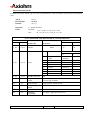
4.8 Configuration menu
Printers are generally shipped with all the functions and parameters pre-set at the factory. It is possible to
change settings for various printer functions and to run certain tests using the configuration menu. Selecting
functions or changing settings is done through the scrolling configuration menu feature. This feature prints
instructions on the receipt for selecting and changing any of the functions and parameters.
Caution:
Be extremely careful changing any of the printer settings to avoid inadvertently changing other
settings that might affect the performance of the printer.
4.8.1 How to enter
-
Push paper feed button
Reset the printer and hold paper feed button.
4.8.2 How to adjust parameters
-
After a self-test, the printer will enter in configuration menu.
Follow all the instructions on the scrolling menu.
Press the Paper Feed Button to make the selections.
The instructions indicate whether to select something with a short click, a long click, or a series
of short clicks. Indicate Yes with a long click, No with a short click.
Press and hold the Paper Feed Button for at least one second for a long click. Press the Paper
Feed Button quickly for a short click.
4.8.3 How to quit
At the end of your configuration, the printer asks for a reset and your configuration will be saved in
the EEPROM.
- Reset the printer
APOS Premium Printer Series User Manual
Page 33 /136
Reference: FDE 3107312 Issue A
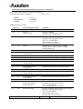
4.8.4 List of parameters that can be changed
-
Hardware Options
Diagnostics Modes
Communication Options
Print Options
Set Hardware Options
Print density
80%
90%
100%
110%
120%
Maximum Power
60 W
75 W
90 W
Pre-Heating
Enabled
Disabled
Max Speed
100 mm/sec
130 mm/sec
Knife Option
Enabled
Disabled
Partial cut Distance
125 Steps
130 Steps
135 Steps
140 Steps
145 Steps
Set Communication Options
Interface Type
RS232
USB
Baud Rate
115200
57600
38400
19200
9600
4800
2400
1200
Data Bits
8
7
Stop Bit(s)
1
2
Parity
No Parity
Even Parity
Odd Parity
Flow Control
DTR/DSR
XON/XOFF
Reception Errors
Print '?'
Ignore Errors
APOS Premium Printer Series User Manual
Page 34 /136
Set Diagnostics Mode
Off
Datascope
Receipt Test
Set Print Options
Default LPI
6 LPI
7.52 LPI
CR Usage
Ignore CR
Print CMD
Queue Ticket Mode
Disabled
Header First
Footer First
Default Font
User Defined
Resident
Default Code Page
437
850
852
858
860
862
863
865
866
1252
Katakana
Reference: FDE 3107312 Issue A
5
LIST OF CONTROL CODES
Control codes are non-printable characters or sequences of characters, which affect the subsequent
operation of the printer. For your convenience, they are grouped in logical sets of commands, which can be
used in the same context.
Code (Hexadecimal)
09
0A
0C
0D
10
10 04 n
10 05 n
11 n1...nl
12
13
14 n
15 n
16 n
17
18
19
1A
1B “BMP file”
1B 07
1B 0C
1B 12
1B 14 n
1B 16 n
1B 20 n
1B 21 n
1B 24 n1 n2
1B 25 n
1B 26 s c1 c2 n1 d1...nn dn
1B 27 m a2 a1 a0 d1 … dn
1B 2A m n1 n2 d1...dn
1B 2D n
1B 2E m n rL rH d1 … dn
1B 32
1B 33 n
1B 34 m a2 a1 a0
1B 3A 30 30 30
1B 3F n
1B 40
Command
Horizontal Tab
Print and Feed One Line
Print and Return to Standard Mode
Activate Carriage Return
Clear Printer
Real Time Status Transmission
Real Time Recovery From Fault
Print Raster Graphics
Select Double-Wide Characters
Select Single-Wide Characters
Feed n Print Lines
Feed n Dot Rows
Add n Extra Dot Rows
Print
Cancel Print Data in Page Mode
Perform Full Knife Cut
Perform Partial Knife Cut
Download BMP Logo
Activate Internal Printer Buzzer
Print Data in Page Mode
Select 90 Degree Counter-Clockwise Rotated Print
Set Column
Select Pitch (Column Width)
Set Right-Side Character Spacing
Select Print Mode
Set Absolute Starting Position
Select Character Set
Define User-Defined Character Set
Write to User Data Storage
Select Bit Image Mode
Select or Cancel Underline Mode
Print Advanced Raster Graphics
Set Line Spacing to 1/6 Inch
Set Line Spacing
Read from User Data Storage
Copy Character Set from ROM to RAM
Cancel User-Defined Character
Initialize Printer
APOS Premium Printer Series User Manual
Page 35 /136
Page
49
44
100
44
40
96
92
69
56
56
44
45
45
46
100
41
41
75
108
101
56
46
63
49
55
50
66
64
117
70
57
69
46
47
117
68
66
40
Reference: FDE 3107312 Issue A
Code (Hexadecimal)
1B 44 [n]...k NUL
1B 45 n
1B 47 n
1B 49 n
1B 4A n
1B 4B n1 n2 d1...dn
1B 4C
1B 52 n
1B 53
1B 54 n
1B 56 n
1B 57 n1 n2...n8
1B 59 n1 n2 d1...dn
1B 5B 7D
1B 5C n1 n2
1B 61 n
1B 63 34 n
1B 63 35 n
1B 64 n
1B 69
1B 6D
1B 70 m n1 n2
1B 74 n
1B 75 00
1B 76
1B 7B n
1C 44 f8 t w h sL sH nL nH {d}
1C 45 f8
1C 46 t
1C 47 w h {d}
1C 48
1C 4C f8 t w h {d}
1D 01
1D 02 nn
1D 03 n
1D 04 n
1D 05
1D 06
1D 07
1D 08
1D 09
1D 0E
1D 0F
1D 10 n
Command
Set Horizontal Tab Positions
Select or Cancel Emphasized Mode
Select or Cancel Double Strike
Select or Cancel Italic Print
Print and Feed Paper
Select Single-Density Graphics
Select Page Mode
Select International Character Set
Select Standard Mode
Select Print Direction in Page Mode
Select or Cancel 90 Degree Clockwise Rotated Print
Set Print Area in Page Mode
Select Double-Density Graphics
Switch to Flash Download Mode
Set Relative Print Position
Select Justification
Select Sensors to Stop Printing
Enable or Disable Panel Button
Print and Feed n Lines
Perform Full Knife Cut
Perform Partial Knife Cut
Generate Solenoid Pulse
Select International Character Set
Transmit cash drawer status
Transmit Paper Sensor Status
Select or Cancel Upside-down Print Mode
Download Double Byte Font
Download Double Byte Font Complete
Read font information and checksum
Download and print one character
Check EasyFont compatibility
Download Single Byte Font
Return Flash Memory Size
Select Flash Memory Sector to Download
Real Time Recovery From Fault
Real Time Status Transmission
Real Time Printer Status Transmission
Get Flash Firmware CRC Status
Return Boot Sector CRC
Return SRAM Size
Return CPU Frequency
Erase All Flash Contents Except Boot Sector
Return Main Program Flash CRC
Erase Selected Flash Sector
APOS Premium Printer Series User Manual
Page 36 /136
Page
50
57
58
58
47
72
101
67
102
102
59
104
72
110
51
52
43
117
48
41
41
108
67
77
78
59
122
123
123
124
124
121
110
111
92
94
94
111
111
89
89
112
112
112
Reference: FDE 3107312 Issue A
Code (Hexadecimal)
1D 11 al ah cl ch d1...dn
1D 21 n
1D 22 n
1D 22 55 n1 n2
1D 23 n
1D 24 nL nH
1D 2A n1 n2 d1...dn
1D 2F m
1D 3A
1D 40 n
1D 42 n
1D 48 n
1D 49 n
1D 49 40 n
1D 4C nL nH
1D 50 x y
1D 56 m
1D 56 m n
1D 57 nL nH
1D 5C nL nH
1D 5E r t m
1D 61 n
1D 66 n
1D 68 n
1D 6B m d1...dk NUL
1D 6B m n d1...dk
1D 72 n
1D 73 m n
1D 75 d0 d1 d2 d3 d4 d5 d6 d7
1D 77 n
1D 78
1D FF
1F 01 d1 ……dn
1F 02 n1 n2 n3 n4 n5 n6
1F 03 00 n
1F 03 02 n
1F 03 04 n
1F 03 0A n
1F 03 0B n
1F 03 0F n
1F 03 80 n
1F 03 A0 n
1F 05 n
1F 06 n
Command
Download to Active Flash Sector
Select Character Size
Select Memory Type (SRAM/Flash)
Flash Memory User Sectors Allocation
Select the Current Logo
Set Absolute Vertical Print Position in Page Mode
Define Downloaded Bit Image
Print Downloaded Bit Image
Select or Cancel Macro Definition
Erase User Flash Sector
Select or Cancel White/Black Reverse Print Mode
Select Printing Position of HRI Characters
Transmit Printer ID
Transmit Printer ID, Remote Diagnostics Extension
Set Left Margin
Set Horizontal and Vertical Minimum Motion Units
Select Cut Mode and Cut Paper
Select Cut Mode and Cut Paper
Set Printing Area Width
Set Relative Vertical Print Position in Page Mode
Execute Macro
Select or Cancel Unsolicited Status Mode (USM)
Select Pitch of HRI Characters
Select Bar Code Height
Print Bar Code
Print Bar Code
Transmit Status
Store selected sensor threshold in flash
Store 10 characters user revision number in flash
Select Bar Code Width
Transmit 10 character user revision number
Reset Firmware
Erase Boot Sector + download new boot code
Set Communication Interface Parameters
Set Diagnostics Mode
Set Knife Option
Set Max Power Consumption
Set Partial Cut Distance
Set Preheating Option
Set Default Font
Set Default Code Page
Set Queue Ticket Mode
Select Superscript or Subscript Modes
Set New Boot Code Parameters
APOS Premium Printer Series User Manual
Page 37 /136
Page
113
60
115
115
73
105
74
75
107
116
61
97
81
82
52
53
42
42
53
106
107
85
97
99
98
98
88
89
54
99
54
40
114
129
130
127
125
127
126
128
131
128
61
114
Reference: FDE 3107312 Issue A
Code (Hexadecimal)
1F 0A n
1F 0B 4E 52 4A n
1F 0C 53 50 46 nL nH
1F 0D 43 4C 45 n
1F 26 H cn cm ln [dn1…dnk] lm
1F 56
1F 61 n
1F 62
1F 63 n
1F 64
1F 65 n
1F 69 n
1F 74
1F 76 n
1F 77n
Command
Voltage and Temperature Monitoring
Set Print Density
Max Speed
Reset EEPROM
Define user-Define Character Set With Variable Height
Send Printer Software Version
Process Ticket Counter
Request Ticket Counter
Set Cut Tag
Request Cut Tag
Return Logo Checksum
Active user defined font selection
Print Test Form
Buffered status transmission
Return User Flash Memory Allocation Status
APOS Premium Printer Series User Manual
Page 38 /136
Page
90
126
125
132
65
90
118
118
119
119
76
65
54
78
116
Reference: FDE 3107312 Issue A
6
COMMAND DESCRIPTION
6.1 Command Conventions
The following information describes how each command is organized:
Command Name
A designation (not the ASCII code) used to identify the command.
Description
A brief summary of the command, followed by detailed information, if necessary.
ASCII
Hexadecimal
Decimal
Value or Values
Range
Default
Formulas
the ASCII control code
the Hexadecimal control code
the Decimal control code
a description of the command operand values
the upper and lower limits of the command operand
the command operand default after printer reset
any formula used for this command.
Exceptions
Describes any exceptions to this command, for example, other commands that the command cannot be used
with.
Related Information
This section describes any related information for this command and provides references to other sections
for additional information.
APOS Premium Printer Series User Manual
Page 39 /136
Reference: FDE 3107312 Issue A
6.2 Reset commands
CLEAR PRINTER
Clears the print line buffer without printing and sets the printer to the following condition:
DLE
10
16
ASCII
Hexadecimal
Decimal
Exceptions
None
INITIALIZE PRINTER
Clears the print line buffer and resets the printer to the default settings for the startup configuration (refer to
Default settings below).
Single Wide, Single-High, Non-Rotated, and Left-Aligned characters are set and User-defined characters or
logo graphics are cleared.
ESC @
1B 40
27 64
ASCII
Hexadecimal
Decimal
Default
Character Pitch
Column Width
Extra Dot Rows
Character Set
Printing Position
15.6 CPI
44 characters
3
Default
Column One
Exceptions
None.
RESET FIRMWARE
Reboots the printer.
ASCII
Hexadecimal
Decimal
GS (SPACE)
1D FF
29 255
APOS Premium Printer Series User Manual
Page 40 /136
Reference: FDE 3107312 Issue A
6.3 Paper Cut commands
PERFORM FULL KNIFE CUT
Cuts the receipt. Use either Hex 19 or Hex 1B 69.
There are two codes for this command. Both codes perform the same function.
ASCII
Hexadecimal
Decimal
EM
19
25
ESC i
1B 69
27 105
PERFORM PARTIAL KNIFE CUT
Partially cuts the receipt. The length of the cut can be changed through the configuration menu. The default
setting leaves 0.20 inches (5 mm) of paper on the left edge. See Setting Partial Cut Distance in Diagnostics.
There are two codes for this command. Both codes perform the same function.
ASCII
Hexadecimal
Decimal
SUB
1A
26
ESC m
1B 6D
27 109
Formulas
The cut edge is 144 dot rows or 0.71 inch (18 mm) above the print station.
Exceptions
The command is valid only at the beginning of a line.
APOS Premium Printer Series User Manual
Page 41 /136
Reference: FDE 3107312 Issue A
SELECT CUT MODE AND CUT PAPER
Selects a mode for cutting paper and cuts the paper. There are two formats for this command: one requiring
one parameter m; the other requiring two parameters, m and n; the format is indicated by the parameter m.
ASCII
Hexadecima
l
Decimal
GS V m
1D 56 m
GS V m n
1D 56 m n
29 86 m
29 86 m n
Selects the mode as shown in the table
Determines the cutting position
Value of m
Value of n
Operand:
Limit:
m = cut mode
n = additional distance to feed prior to cut beyond the cut position
OPTION 1:
Decimal:
0 ≤ m ≤ 1 48 ≤ m ≤ 49
65 ≤ m ≤ 66
0 ≤ n ≤ 255
Hex:
00 ≤ m ≤ 01 30 ≤ m ≤ 31
41 ≤ m ≤ 42
00 ≤ n ≤ FF
OPTION 2:
“GS V” OPERAND DEFINITION
M
Decimal
Hex
Cut mode
0, 48
1, 49
65
00, 30
01, 31
41
66
42
Full cut
Partial cut
Feeds paper n x vertical motion units beyond the cut
position, then executes a full cut
Feeds paper n x vertical motion units beyond the cut
position, then executes a partial cut
APOS Premium Printer Series User Manual
Page 42 /136
Reference: FDE 3107312 Issue A
6.4 Sensor commands
SELECT SENSORS TO STOP PRINTING
Selects the paper sensor used to detect out-of-paper. The printer finishes printing the current line and feeds
the paper before stopping.
ESC c 4 n
1B 63 34 n
27 99 52 n
ASCII
Hexadecimal
Decimal
Value of n
Bit
0-1
Sensor status
Sensor
Receipt Paper Near-End
Logical combination of bit1, bit 0
00
01 or 10 or 11
Disabled for paper
Enabled for paper
out detection
out detection
Bits 2- 7 are unused
Default
0
APOS Premium Printer Series User Manual
Page 43 /136
Reference: FDE 3107312 Issue A
6.5 Vertical Positioning and Print Commands
The vertical positioning and print commands control the vertical print positions of characters on the receipt.
PRINT AND FEED ONE LINE
Prints one line from the buffer and feeds paper one line.
ASCII
Hexadecimal
Decimal
LF
0A
10
ACTIVATE CARRIAGE RETURN
Prints one line from the buffer and feeds paper one line. The printer can be set through the configuration
menu to ignore or use this command. Some applications expect the command to be ignored, while others
use it as print command.
ASCII
Hexadecimal
Decimal
CR
0D
13
Related Information
See Ignoring/Using the Carriage Return in Diagnostics for more information.
FEED N PRINT LINES
Feeds the paper n lines at the current line height without printing.
ASCII
Hexadecimal
Decimal
DC4 n
14 n
20 n
Value of n
The number of lines to feed at current line height setting.
Range of n
0-255
APOS Premium Printer Series User Manual
Page 44 /136
Reference: FDE 3107312 Issue A
FEED N DOT ROWS
Feeds the paper n dot rows (n/203 inch, n/8 mm), without printing.
ASCII
Hexadecimal
Decimal
NAK n
15 n
21 n
Value of n
n/203
inch
0-255
Range of n
ADD N EXTRA DOT ROWS
Adds n extra dot rows (n/203 inch, n/8 mm) to the character height to increase space between print lines or
decrease the number of lines per inch.
SYN n
16 n
22 n
ASCII
Hexadecimal
Decimal
Value of n
Number of extra dot rows
Range of n
0-16
Default
3 extra dot rows
Formulas
The following table shows the relationship between the number of lines per inch and each extra dot row
added:
Extra
Lines
Dot
Extra
Lines
Dot
Per Inch
Per Inch
Rows
Rows
Rows
Rows
0
8.5
24
9
6.1
33
1
8.1
25
10
6.0
34
2
7.8
26
11
5.8
35
3
7.5
27
12
5.6
36
4
7.2
28
13
5.5
37
5
7.0
29
14
5.3
38
6
6.8
30
15
5.2
39
7
6.5
31
16
5.1
40
8
6.3
32
APOS Premium Printer Series User Manual
Page 45 /136
Reference: FDE 3107312 Issue A
PRINT
Prints one line from the buffer and feeds paper one line.
ETB
17
23
ASCII
Hexadecimal
Decimal
SET COLUMN
Prints the first character of the next print line in column n, which must be sent for each line not printed at
column one. The value of n is set to one after each line.
ESC DC4 n
1B 14 n
27 20 n
ASCII
Hexadecimal
Decimal
Value of
n
1-44= Standard pitch
1-56= Compressed pitch
Default of n
1
Exceptions
This command cannot be used with Single or Double-Density graphics.
SET LINE SPACING TO 1/6 INCH
Sets the default line spacing to 1/6 of an inch (4,23 mm).
ASCII
Hexadecimal
Decimal
ESC 2
1B 32
27 50
APOS Premium Printer Series User Manual
Page 46 /136
Reference: FDE 3107312 Issue A
SET LINE SPACING
Sets the line spacing to [n x horizontal or vertical motion units] .
The minimum line spacing is 8.5 lines per inch. The line spacing equals the character height when n is too
small.
If the Set Horizontal and Vertical Minimum Motion Units command (1D 50) is used to change the
horizontal and vertical minimum motion unit, the parameters of this command (SetLine Spacing) will be
interpreted accordingly.
ASCII
Hexadecimal
Decimal
ESC 3 n
1B 33 n
27 51 n
Value of n
Range of n
N x vertical motion unit
0-255
Default
0.16 inch (4.23 mm)
Related Information
For more information, see the description of the Set Horizontal and Vertical Minimum Motion Units
command in this document.
PRINT AND FEED PAPER
Prints one line from the buffer and feeds the paper [n x horizontal or vertical motion units]. The line height
equals the character height when n is too small.
If the Set Horizontal and Vertical Minimum Motion Units command (1D 50) is used to change the
horizontal and vertical minimum motion units, the parameters of this command (Print and Feed Paper) will
be interpreted accordingly.
ASCII
Hexadecimal
Decimal
Value of n
ESC J n
1B 4A n
27 74 n
n x horizontal
or vertical
motion units
0-255
Range of n
Related Information
For more information, see the description of the Set Horizontal and Vertical Minimum Motion Units
command in this document.
APOS Premium Printer Series User Manual
Page 47 /136
Reference: FDE 3107312 Issue A
PRINT AND FEED N LINES
Prints one line from the buffer and feeds paper n lines at the current line height.
ASCII
Hexadecimal
Decimal
Range of n
ESC d n
1B 64 n
27 100 n
1-255 (0 is interpreted as 1)
APOS Premium Printer Series User Manual
Page 48 /136
Reference: FDE 3107312 Issue A
6.6 Horizontal Positioning Commands
The horizontal positioning commands control the horizontal print positions of characters on the receipt.
HORIZONTAL TAB
Moves the print position to the next tab position set by the Set Horizontal Tab Positions (1B 44 n1 n2 ...
00) command. The print position is reset to column one after each line.
Tab treats the left margin as column one; therefore changes to the left margin will move the tab positions.
When no tabs are defined to the right of the current position, or if the next tab is past the right margin, Line
Feed is executed. HT has no effect in Page Mode.
Print initialization sets 32 tabs at column 9, 17, 25,
ASCII
Hexadecimal
Decimal
HT
09
9
SET RIGHT-SIDE CHARACTER SPACING
Sets the right side character spacing to [n x horizontal or vertical motion units]. Values for this command
are set independently in standard and page mode.
The units of horizontal and vertical motion are specified by the Set Horizontal and Vertical Minimum
Motion Units (GS P) command. Changes in the horizontal or vertical units do not affect the current rightside character spacing. When the horizontal or vertical motion unit is changed by the Set Horizontal and
Vertical Minimum Motion Units (GS P) command the value must be in even units and not less than the
minimum amount of horizontal movement.
In standard mode the horizontal motion unit is used.
In page mode the horizontal or vertical motion unit differs and depends on the starting position of the
printable area. When the starting printing position is the upper left or lower right of the printable area (set
by Select Print Direction in Page Mode, ESC T) the horizontal motion unit (x) is used. When the starting
printing position is the upper right or lower left of the printable area (set by Select Print Direction in Page
Mode, ESC T) the vertical motion unit (y) is used.
ASCII
Hexadecimal
Decimal
Range of n
Default
ESC SP n
1B 20 n
27 32 n
0 – 32
0
APOS Premium Printer Series User Manual
Page 49 /136
Reference: FDE 3107312 Issue A
SET ABSOLUTE STARTING POSITION
Sets the print starting position to the specified number of dots (up to the right margin) from the beginning
of the line. The print starting position is reset to the first column after each line.
If the Set Horizontal and Vertical Minimum Motion Units command (1D 50) is used to change the
horizontal and vertical minimum motion unit, the parameters of this command (Set Absolute Print Position)
will be interpreted accordingly.
ASCII
Hexadecimal
Decimal
ESC $ n1 n2
1B 24 n1 n2
27 36 n1 n2
[n x horizontal or vertical motion units] = Number of dots to be moved
from the beginning of the line
n1 = Remainder after dividing n by 256
n2 = Integer after dividing n by 256
Value of n
The values for n1 and n2 are two bytes in low byte, high byte word orientation.
Formulas:
The example shows how to calculate 280 dots as the absolute starting position.
280/256 = 1, remainder of 24
n1 = 24
n2 = 1
Related Information
This command is also used in graphics mode. See Graphics Commands in this document for more
information.
For more information, see the description of the Set Horizontal and Vertical Minimum Motion Units
command (1D 50) in this document.
SET HORIZONTAL TAB POSITIONS
Sets up to 32 horizontal tab-position n columns from column one, but does not move the print position. See
the Horizontal Tab command (09).
The tab positions remain unchanged if the character widths are changed after the tabs are set. The command
ends with hexadecimal 00; hexadecimal 1B 44 00 clears all tabs.
ASCII
Hexadecimal
Decimal
ESC D [n]…k NUL
1B 44 [n]…k NUL
27 68 [n]…k 0
Column number for tab minus one
(n is always less than or equal to the current selected column width)
0-32
Value of k
Every 8 characters from column. 1 (9, 17, 25, etc.) for normal print
Default
Formulas:
Set the tab positions in ascending order and put Hex 00 at the end.
Hex 1B 44 00 (number of tabs not specified) clears all tab positions.
Value of n
Exceptions:
The tabs cannot be set higher than the column width of the current pitch:
1-44= Standard pitch
1-56= Compressed pitch
APOS Premium Printer Series User Manual
Page 50 /136
Reference: FDE 3107312 Issue A
SET RELATIVE PRINT POSITION
Moves the print-starting position the specified number of dots times horizontal motion unit either right (up
to the right margin) or left (up to the left margin) of the current position. The print starting position is reset
to the first column after each line.
ASCII
Hexadecimal
Decimal
ESC \ n1 n2
1B 5C n1 n2
27 92 n1 n2
Value of n
To Move the Relative Starting Position Right of the Current Position:
[n x horizontal or vertical motion units] = Number of dots to be moved right of the current position
n1 = Remainder after dividing n by 256
n2 = Integer after dividing n by 256
The values for n1 and n2 are two bytes in low byte, high byte word orientation.
To Move the Relative Starting-Position Left of the Current Position:
[n x horizontal or vertical motion units] = Number of dots to be moved left of the current position
n1 = Remainder after dividing (65,536-n) by 256
n2 = Integer after dividing (65,536-n) by 256
The values for n1 and n2 are two bytes in low byte, high byte word orientation.
Formulas
To move to the left:
The example shows how to set the relative position 20 dots to the left of the current position.
65,536-20 = 65516
65,516/256 = 255, remainder of 236
n1 = 236, n2 = 255
To move to the right:
The example shows how to set the relative position 20 dots to the right of the current position.
20/256 = 0, remainder of 20
n1 = 20, n2 = 0
Related Information
If the Set Horizontal and Vertical Minimum Motion Units command (1D 50) is used to change the
horizontal and vertical minimum motion unit, the parameters of this command (Set Relative Print Position)
will be interpreted accordingly. For more information, see the description of the Set Horizontal and
Vertical Minimum Motion Units command (1D 50) in this document.
APOS Premium Printer Series User Manual
Page 51 /136
Reference: FDE 3107312 Issue A
SELECT JUSTIFICATION
Specifies the alignment of characters, graphics, logos, and bar codes (see the value of n table).
ESC a n
1B 61 n
27 97 n
ASCII
Hexadecimal
Decimal
Range of n
0, 48 = Left aligned
1, 49 = Center aligned
2, 50 = Right aligned
0-2, 48-50
Default
0 (Left aligned)
Value of n
Exceptions :
The command is valid only at the beginning of a line.
SET LEFT MARGIN
Sets the left margin of the printing area. The left margin is set to (((nH X 256) + nL) times horizontal
motion unit) inches. The Set Horizontal and Vertical Minimum Motion Units command (1D 50) sets the
horizontal motion units. This command is described below.
The Set Printing Area Width command (1D 57), which follows this command, sets the width of the printing
area. See the Set Printing Area Width command (1D 57) in this document for a description of that
command.
If the setting exceeds the printable area, the maximum value of the printable area is used. The maximum
printable area is 576 dots. See the illustration.
ASCII
Hexadecimal
Decimal
GS L nL nH
1D 4C nL nH
29 76 nL nH
0-255
Range of nL
0-255
Range of nH
576 dots (the maximum printable area).
Default
Formulas
To set the left margin to one inch at the horizontal motion unit of 1/203 inches, send the four-byte string:
GS L 203 0
Or, to set the left margin to two inches at the horizontal motion unit of 1/203 units per inch, send the fourbyte string: GS L 150 1
Where 2 inches = 406/203, and 406 = (1 X 256) + 150.
←
Printable area 576 dots →
←Left margin→
←Printing area width→
APOS Premium Printer Series User Manual
Page 52 /136
Reference: FDE 3107312 Issue A
SET HORIZONTAL AND VERTICAL MINIMUM MOTION UNITS
Sets the horizontal and vertical motion units to 1/x inch and 1/y inch respectively.
When x or y is set to 0, the default setting for that motion unit is used.
GS P x y
1D 50 x y
29 80 x y
ASCII
Hexadecimal
Decimal
Value of x
Value of y
Range of x
Range of y
Default of x:
Default of y:
Horizontal
Vertical
0 – 255
0 - 255
180
360
SET PRINTING AREA WIDTH
Sets the width of the printing area. If the setting exceeds the printable area, the maximum value of the
printable area is used. The width of the printing area is set to (((nH X 256) + nL) times horizontal motion
unit) inches. The Set Horizontal and Vertical Minimum Motion Units command (1D 50), described earlier
in this document, sets the horizontal motion units.
The width of the printing area follows the Set Left Margin command (1D 4C). See the Set Left Margin
command (GS L) earlier in this document for a description.
GS W nL nH
1D 57 nL nH
29 87 nL nH
ASCII
Hexadecimal
Decimal
Range of nL
Range of nH
Default
0-255
0-255
576 dots (the maximum printable area).
Formulas
To set the width of the printing area to one inch at the horizontal motion unit of 1/203 inches, send the
four-byte string: GS W 203 0
Or, to set the width of the printing area to two inches at the horizontal motion unit of 1/203 units per inch,
send the four-byte string: GS W 150 1
Where 2 inches = 406/203, and 406 = (1 X 256) + 150.
←
Printable area 576 dots →
←Left margin→ ←Printing area width→
Exceptions
This command is effective only at the beginning of a line.
If the setting exceeds the printable area, the maximum value of the printable area is used. The maximum
printable area is 576 dots (see illustration).
APOS Premium Printer Series User Manual
Page 53 /136
Reference: FDE 3107312 Issue A
6.7 Printer configuration
STORE 10 CHARACTERS USER REVISION NUMBER IN FLASH
This command will store a 10-character user defined revision number downloaded to the printer.
ASCII
Hexadecimal
Decimal
Operand:
Limit:
GS u d0 d1 d2 d3 d4 d5 d6 d7 d8 d9
1D 75 d0 d1 d2 d3 d4 d5 d6 d7 d8 d9
29 117 d0 d1 d2 d3 d4 d5 d6 d7 d8 d9
dn = downloaded revision number
Decimal:
32 ≤ dn ≤ 126
Hex:
Default:
Note:
Decimal:
Hex:
20 ≤ dn ≤ 7E
dn = 47
dn = 30
The user defined revision number is printed on the configuration menu.
TRANSMIT 10 CHARACTERS USER REVISION NUMBER
This command will transmit the 10-character printable ASCII user defined revision number.
ASCII
Hexadecimal
Decimal
GS x
1D 78
29 120
Note: The returned revision number may contain a bit pattern that is valid for returned status. Care should
be taken not to confuse this returned data with any other returned data.
PRINT TEST FORM
This command will print the configuration setting ticket repeatedly.
ASCII
Hexadecimal
Decimal
US t
1F 74
31 116
Note: This command will assert busy and will ignore all input data until all tickets have been printed.
APOS Premium Printer Series User Manual
Page 54 /136
Reference: FDE 3107312 Issue A
6.8 Print Characteristics Commands
These commands control what the printed information looks like, selection of character sets, definition of
custom-defined characters, and setting of margins. The commands are described in order of their
hexadecimal codes.
SELECT PRINT MODE
Selects the print mode: standard, compressed, emphasized, underlined, double high or doublewide.
ESC ! n
1B 21 n
27 33 n
ASCII
Hexadecimal
Decimal
Value of n
See table
Value of n
Bit1
Bit 0
Function
Pitch
(See chart below)
Bit 3
Emphasized Mode
Bit 4
Double High
Bit 5
Double Wide
Bit 7
Underlined Mode
1 Bits 1, 2 and 6 are not used
Default
0
Standard Pitch
1
Compressed Pitch
Canceled
Canceled
Canceled
Canceled
Set
Set
Set
Set (bar thickness = 2)
0 (for bits 0, 3, 4, 5, 7)
This command and select pitch (column width) command (1B 16-n) affect pitch selection.
Pitch
Standard
Compressed
Columns
44
56
CPI
15.6
20.3
Selects the print mode: Standard, compressed, emphasized, underlined, double high or doublewide.
Exceptions
Refer to the above table for exceptions.
Related Information
See the Print Specifications Guide for a description of standard and compressed character pitches.
APOS Premium Printer Series User Manual
Page 55 /136
Reference: FDE 3107312 Issue A
SELECT DOUBLE-WIDE CHARACTERS
Prints doublewide characters. The printer is reset to singlewide mode after a line has been printed or the
Clear Printer (10) command is received. Doublewide characters may be used in the same line with
singlewide characters.
ASCII
Hexadecimal
Decimal
DC2
12
18
Exceptions
Doublewide characters may not be used in the same line with single or double-density graphics.
SELECT SINGLE-WIDE CHARACTERS
Prints singlewide characters. Singlewide characters may be used in the same line with doublewide
characters.
ASCII
Hexadecimal
Decimal
DC3
13
19
Exceptions
Singlewide characters may not be used in the same line with single or double-density graphics.
SELECT 90 DEGREE COUNTER-CLOCKWISE ROTATED PRINT
Rotates characters 90 degrees counter-clockwise. The command remains in effect until the printer is reset
or until a Clear Printer (10) or Cancel Rotated Print (1B 56) command is received.
ASCII
Hexadecimal
Decimal
ESC DC2
1B 12
27 18
Related Information
See “Summary of Rotated Printing” in this document.
APOS Premium Printer Series User Manual
Page 56 /136
Reference: FDE 3107312 Issue A
SELECT OR CANCEL UNDERLINE MODE
Turns underline mode on or off. Underlines cannot be printed for spaces set by the Horizontal Tab, Set
Absolute Start Position, or Set Relative Print Position commands.
Underline mode may also be turned ON and OFF with the Select Print Mode(s) command (1B 21).
However with that command the bar thickness is not selectable.
ASCII
Hexadecimal
Decimal
Value of n
Default
ESC - n
1B 2D n
27 45 n
0, 48 = Cancel underline mode
1- 7,49-55 = Select underline mode and bar thickness in number of dots
0 (Cancel underline mode)
Exceptions
This command is ignored if n is out of the specified range.
SELECT OR CANCEL EMPHASIZED MODE
Starts or stops emphasized printing. The printer is reset to the standard print mode after a Clear Printer (10)
command is received.
ASCII
Hexadecimal
Decimal
ESC E n
1B 45 n
27 69 n
Value of n
0 = Off
Default
1 = On
(When 0 and 1 are the Least Significant Bit, LSB)
0 (Off)
Exceptions
Only the lowest bit of n is effective.
Emphasized printing cannot be used with bit-images or downloaded bit-images.
Related Information
This command and the Select Print Mode(s) command (1B 21) function identically. They should have the
same setting when used together.
APOS Premium Printer Series User Manual
Page 57 /136
Reference: FDE 3107312 Issue A
SELECT OR CANCEL DOUBLE STRIKE
Turns double strike mode on or off. (identical to Emphasized mode). The printer is reset to the standard
print mode after a Clear Printer (10) command is received.
ESC G n
1B 47 n
27 71 n
ASCII
Hexadecimal
Decimal
Value of n
0 = Off
Default
1 = On
(When 0 and 1 are the Least Significant Bit, LSB)
0 (Off)
Exceptions
Only the lowest bit of n is effective.
Double-strike printing cannot be used with bit-images or downloaded bit-images.
SELECT OR CANCEL ITALIC PRINT
Turns Italic print mode on or off. The printer is reset to the standard print mode after a Clear Printer (10)
command is received.
ESC I n
1B 49 n
27 73 n
ASCII
Hexadecimal
Decimal
Value of n
Default
0 = Off
1 = On
(When 0 and 1 are the Least Significant Bit, LSB)
0 (Off)
Exceptions
Only the lowest bit of n is valid.
APOS Premium Printer Series User Manual
Page 58 /136
Reference: FDE 3107312 Issue A
SELECT OR CANCEL 90 DEGREE CLOCKWISE ROTATED PRINT
Rotates characters 90 degrees clockwise. The command remains in effect until the printer is reset or until a
Clear Printer (10) or Rotated Print (1B 12) command is received. See Summary of Rotated Printing in this
document.
ASCII
Hexadecimal
Decimal
Value of n
Default
ESC V n
1B 56 n
27 86 n
0 = Cancel
1 = Set
0 (Cancel)
SELECT OR CANCEL UPSIDE DOWN PRINT MODE
Prints upside-down characters. The command may be combined with Clock Wise Rotated print (1B 56) or
Counter Clock Wise Rotated print (1B 12). The character order is inverted in the buffer so text is readable.
Only bit 0 is used. Bits 1-7 are not used. See Summary of Rotated Printing in this document for more
information.
ASCII
Hexadecimal
Decimal
Value of n
Default
ESC { n
1B 7B n
27 123 n
0 = Cancel
1 = Set
0 (Cancel)
Exceptions
The command is valid only at the beginning of a line.
It cannot be used with right side up characters on the same line.
APOS Premium Printer Series User Manual
Page 59 /136
Reference: FDE 3107312 Issue A
SELECT CHARACTER SIZE
Selects the character height using bits 0 to 2 and selects the character width using bits 4 to 6, as follows:
Character Width Selection
Hex
Decimal
00
0
10
16
20
32
30
48
40
64
50
80
60
96
70
112
Width
1 (normal)
2 (two times width)
3 (three times width)
4 (four times width)
5 (five times width)
6 (six times width)
7 (seven times width)
8 (eight times width)
Character Height Selection
Hex
Decimal
00
0
01
1
02
2
03
3
04
4
05
5
06
6
07
7
Height
1 (normal)
2 (two times height)
3 (three times height
4 (four times height)
5 (five times height)
6 (six times height)
7 (seven times height)
8 (eight times height)
This command is effective for all characters (except for HRI characters).
In standard mode (non-page mode), the vertical direction is the paper feed direction, and the horizontal
direction is perpendicular to the paper feed direction. However, when character orientation changes in 90degree clockwise-rotation mode, the relationship between vertical and horizontal directions is reversed.
In page mode, vertical and horizontal direction are based on the character orientation. When characters are
enlarged with different sizes on one line, all the characters on the line are aligned at the baseline.
The Select Print Mode (ESC !) command can also select or cancel double-width and double-height modes.
However, the setting of the last received command is effective.
ASCII
Hexadecimal
Decimal
Value of n
GS ! n
1D 21 n
29 33 n
1-8 = vertical number of times normal font
1-8 = horizontal number of times normal font
00-07, 10-17, …, 70-77
00 hexadecimal
Range of n
Default of n
Exceptions
If n is out of the defined range, this command is ignored.
APOS Premium Printer Series User Manual
Page 60 /136
Reference: FDE 3107312 Issue A
SELECT OR CANCEL WHITE/BLACK REVERSE PRINT MODE
Turns on White/Black reverse printing mode. In White/Black reverse printing mode, print dots and nonprint dots are reversed, which means that white characters are printed on a black background. When the
White/Black reverse printing mode is selected it is also applied to character spacing which is set by RightSide Character Spacing (ESC SP).
This command can be used with built-in characters and user-defined characters, but does not affect the
space between lines.
White/Black Reverse Print Mode does not affect bit image, downloaded bit image, bar code, HRI
characters, and spacing skipped by Horizontal Tab (HT), Set Absolute Starting Position (ESC $), and Set
Relative Print Position (ESC \).
GS B n
1D 42 n
29 66 n
ASCII
Hexadecimal
Decimal
Value of n
0 = Off
Default
1 = On
(When 0 and 1 are the Least Significant Bit, LSB)
0 (Off)
Exceptions
Only the lowest bit of n is valid.
SELECT SUPERSCRIPT OR SUBSCRIPT MODES
Turns superscript or subscript modes on or off. This attribute may be combined with other characters size
settings commands (12, 13, 1B 21 n, 1D 21 n)
ASCII
Hexadecimal
Decimal
Value of n
Default
US ENQ n
1F 05 n
31 05 n
0 = Normal character size
1 = Select subscript size
2 = Select superscript size
0 (normal size)
Exceptions
This command is ignored if n is out of the specified range.
APOS Premium Printer Series User Manual
Page 61 /136
Reference: FDE 3107312 Issue A
SUMMARY OF ROTATED PRINTING
The table shows the combinations of upside-down print, 90 degree clockwise rotated print, and 90-degree
counterclockwise rotated print.
90-degree clockwise rotated and 90-degree counterclockwise-rotated print commands are mutually
exclusive:
The setting of the last received command is effective.
The samples of the print show only the normal size characters. Doublewide and double-high characters are
printed in the same orientation.
They may also be mixed on the same line.
Upside Down
1B 7B n
Rotated CW
1B 56 n
Rotated CCW
1B 12
Resulting Output
Canceled
Canceled
Canceled
1 (See Below)
Canceled
Set
Canceled
2 (See Below)
Set
Canceled
Canceled
3 (See Below)
Set
Set
Canceled
4 (See Below)
Canceled
Canceled
Set
5 (See Below)
Set
Canceled
Set
6 (See Below)
Note: Right-side up and upside down print modes cannot be mixed on the same line.
APOS Premium Printer Series User Manual
Page 62 /136
Reference: FDE 3107312 Issue A
6.9 Font commands
SELECT PITCH (COLUMN WIDTH)
Selects the character pitch for a print line
ASCII
Hexadecimal
Decimal
ESC SYN n
1B 16 n
27 22 n
Value of n
0 = Standard pitch
1 = Compressed pitch
Default
0 (Standard pitch)
Formulas
The following table provides the print characteristics for both pitches on the receipt station.
Pitch
Standard
Compressed
Columns
44
56
CPI
15.6
20.3
Related Information
See Print Specifications for a description of both pitches.
APOS Premium Printer Series User Manual
Page 63 /136
Reference: FDE 3107312 Issue A
DEFINE USER-DEFINED CHARACTER SET
Defines and enters downloaded characters into RAM. The command may be used to overwrite single
characters. User-defined characters are available until power is turned off or the Initialize Printer command
(1B 40) is received.
Any invalid byte (s, c1, c2, n1, n2) aborts the command.
ASCII
Hexadecimal
Decimal
ESC & s c1 c2 n1 d1 ... nn dn
1B 26 s c1 c2 n1 d1 ... nn dn
27 38 s c1 c2 n1 d1 ... nn dn
Values and Ranges
s
c
n
d
= 3 (fixed value), the number of bytes (vertically) in the character cell
= the ASCII codes of the first (c1) and last (c2) characters respectively
c1 = Hex 20-FF (20 is always printed as a space)
c2 = Hex 20-FF (20 is always printed as a space)
To define only one character, use the same code for both c1 and c2
= the number of dot columns for the nth character as specified by n1 ... nn
n = 1-16
= the column data for the nth character as specified by d1 ... dn
The number of bytes for a character cell is s x n1
The bytes are printed down and across each cell
See the illustration:
Top of Character
d1 d4
MSB
d2 d5
dn
d3
dn
LSB
Related information
See 1D 22 n ( Select memory type ) to save User Defined characters.
APOS Premium Printer Series User Manual
Page 64 /136
Reference: FDE 3107312 Issue A
DEFINE USER-DEFINED CHARACTER SET WITH VARIABLE HEIGHT
Command format is similar to existing command 1B 26. The only difference resides in the height encoding
H indicates the height in number of dots instead of number of byte (1B 26) to provide better resolution.
Data are still encoded vertically.
max dimensions : Hmax = 64, Wmax = 48
ASCII
Hexadecimal
Decimal
US & H cn cm ln [dn1…dnk] lm [dm1…dmk]
1F 26 H cn cm ln [dn1…dnk] lm [dm1…dmk
31 38 H cn cm ln [dn1…dnk] lm [dm1…dmk]
Values and Ranges
Parameter H indicates character height in number of dots, and does not have to be dividable by 8.
From 1 to 8 dots high => 1 data byte per column
From 9 to 16 dots high => 2 data bytes per column
From 17 to 24 dots high => 3 data bytes per column
Etc…
Top of Character
d1 d4
MSB
d2 d5
dn
d3
dn
LSB
ACTIVE USER-DEFINED FONT SELECTION
ASCII
Hexadecimal
Decimal
US i n
1F 69 n
31 105 n
n = 0, 1, 2, 3
default = 0
Selects the active user defined font used by commands 1B 26, 1F 26, 1B 25, 1B 3A, 1B 3F.
Setting remains unchanged until printer reboots, or command 1B 40 resets active user defined font to
default.
APOS Premium Printer Series User Manual
Page 65 /136
Reference: FDE 3107312 Issue A
CANCEL USER-DEFINED CHARACTER
Cancels the pattern defined for the character code specified by n. After the user-defined character is
canceled, the corresponding pattern from current active ROM Code Page is printed.
ASCII
Hexadecimal
Decimal
Range of n
ESC ? n
1B 3F n
27 63 n
32-255
Exceptions
This command is ignored if n is out of range or if the user-defined character is not defined.
SELECT CHARACTER SET
Selects the character set. When an undefined RAM character is selected, current active ROM Code Page
character is used. See the Printing Specification Guide for the character sets.
ASCII
Hexadecimal
Decimal
Value of n
Range of n
Default
ESC % n
1B 25 n
27 37 n
0 = Code Page 437
1 = User Defined (RAM)
2 = Code Page 850
0-2
0 (Code Page 437)
APOS Premium Printer Series User Manual
Page 66 /136
Reference: FDE 3107312 Issue A
SELECT CHARACTER CODE TABLE
SELECT INTERNATIONAL CHARACTER SET
Selects the character set to be used. See Print Specifications for the character sets.
There are two codes for this command. Both codes perform the same function.
ESC R n
1B 52 n
27 82 n
ASCII:
Hexadecimal:
Decimal:
Default
ESC t n
1B 74 n
27 116 n
n
Decimal
Hex
Code Page
0
1
2
3
4
5
6
7
8
9
10
48
49
50
51
52
00
01
02
03
04
05
06
07
08
09
0A
30
31
32
33
34
437 : US
850 : Multilingual
852 : Latin 2, Slavic
860 : Portuguese
863 : Canadian French
865 : Nordic
858 : Multilingual with Euro
866 : Cyrillic, Russian
1252 : Windows, Latin 1
862 : Hebrew
Katakana
Easy Font single n°0
Easy Font single n°1
Easy Font single n°2
Easy Font single n°3
Easy Font double
6 (Code Page 858), selectable through configuration menu
Related Information
This command may also be known as Select International Character Set.
APOS Premium Printer Series User Manual
Page 67 /136
Reference: FDE 3107312 Issue A
COPY CHARACTER SET FROM ROM TO RAM
Copies characters in the active ROM set to RAM. Use this command to re-initialize the User-Defined
Character Set.
ASCII
Hexadecimal
Decimal
Default
ESC : 0 0 0
1B 3A 30 30 30
27 58 0 0 0
current active ROM Code Page
Related Information
To modify characters in one of the character set variations, such as Rotated Print, Select one of the Rotated
Print commands, copy to RAM, then use the Define User-Defined Character Set command (1B 26).
APOS Premium Printer Series User Manual
Page 68 /136
Reference: FDE 3107312 Issue A
6.10 Graphics Commands
These commands are used to enter and print graphics data and are described in order of their hexadecimal
codes.
PRINT RASTER GRAPHICS
Prints one row of data. n1 . .. nl: bytes describing the line to print.
ASCII
Hexadecimal
Decimal
Value of n
Range
DC1 n1 ...nl
11 n1 ...nl
17 n1 ...nl
n1…n72 = Data bytes
0-255
Exceptions
Raster graphics is not available in Page Mode.
PRINT ADVANCED RASTER GRAPHICS
Prints a horizontal raster of graphics data one or multiple times. Horizontal offset and number of data bytes
are variable and specified by parameters.
ASCII
Hexadecimal
Decimal
Value of m :
Value of n :
Value of r :
d1 … dn :
ESC . m n rL rH d1 ... dn
1B 2E m n rL rH d1 ... dn
27 46 m n rL rH d1 ... dn
horizontal offset from left margin = 8 x m dots
number of data bytes that compose the raster
number of times the raster has to be printed = 256 x rH + rL
Data bytes
Range
0 ≤ m ≤ 72
0 ≤ n ≤ 72
0 ≤ r ≤ 65535
0 ≤ d1…dn ≤ 255
Exceptions
Advanced Raster graphics is not available in Page Mode.
APOS Premium Printer Series User Manual
Page 69 /136
Reference: FDE 3107312 Issue A
SELECT BIT IMAGE MODE
Sets the print resolution and enters one line of graphics data into the print buffer. Excess data is accepted
but ignored. Any print command is required to print the data, after which the printer returns to normal
processing mode. See the illustration for graphic representations of the bit image.
ASCII
Hexadecimal
Decimal
ESC * m n1 n2 d1 ... dn
1B 2A m n1 n2 d1 ... dn
27 42 m n1 n2 d1 ... dn
Value of m
Value
of m
0
1
32
33
Mode
8 Dot Single Density
8 Dot Double Density
24 Dot Single Density
24 Dot Double Density
No. of Dots
(Vertical)
8 (68 DPI)
8 (68 DPI)
24 (203 DPI)
24 (203 DPI)
No. of Dots
(Horizontal)
0-288 (101 DPI)
0-576 (203 DPI)
0-288 (101 DPI)
0-576 (203 DPI)
No. of
Dots/Line
8 x 288
8 x 576
24 x 288
24 x 576
Value of n
Value of n (8-Dot
Single Density Mode)
n1 + (256 x n2)
Value of n (24-Dot Single
Density Mode)
3 x [n1 + (256 x n2)]
APOS Premium Printer Series User Manual
Page 70 /136
Value
of d
Number of Bytes of Data
(Printed Down, Then Across)
Reference: FDE 3107312 Issue A
Related Information
8-Dot Single-Density Mode
Receipt
MSB
Top of Bit Image
d1 d2 d3 d4
dn
dn
LSB
24-Dot Single-Density Mode
Top of Bit Image
d1 d4 d7
MSB
d2 d5
dn
d3 d6
dn
LSB
APOS Premium Printer Series User Manual
Page 71 /136
Reference: FDE 3107312 Issue A
SELECT SINGLE-DENSITY GRAPHICS
Enters one line of 8-dot single-density graphics into the print buffer. Any print command is required to
print the line, after which the printer returns to normal processing mode. Single-density mode allows 0-288
dot columns for 80-mm paper. The number of bytes sent is represented by the formulas in table.
Each bit corresponds to two horizontal dots. Compare to Set Bit Image Mode (1B 2A, m=0) earlier in this
document.
ASCII
Hexadecimal
Decimal
ESC K n1 n2 d1 ... dn
1B 4B n1 n2 d1 ... dn
27 75 n1 n2 d1 ... dn
Value of n
Value of n (8-Dot
Single Density
Mode)
n1 + (256 x n2)
Value of n (24-Dot
Single Density
Mode)
3 x [n1 + (256 x n2)]
Value of d
Number of Bytes of
Data (Printed Down,
Then Across)
Formulas
See the above table.
SELECT DOUBLE-DENSITY GRAPHICS
Enters one line of 8-dot double-density graphics into the print buffer. Any print command is required to
print the line, after which the printer returns to normal processing mode. Double-density mode allows 0576 dot.
The number of bytes sent is represented by the formulas in the table.
Each bit corresponds to one horizontal dot. Compare to Set Bit Image Mode (1B 2A, m=1) earlier in this
document.
ASCII
Hexadecimal
Decimal
ESC Y n1 n2 d1 ... dn
1B 59 n1 n2 d1 ... dn
27 89 n1 n2 d1 ... dn
Value of n
Value of n (8-Dot
Single Density
Mode)
n1 + (256 x n2)
Value of n (24-Dot
Single Density
Mode)
3 x [n1 + (256 x
n2)]
Value of d
Number of Bytes of Data
(Printed Down, Then
Across)
Formulas
See the above table.
APOS Premium Printer Series User Manual
Page 72 /136
Reference: FDE 3107312 Issue A
6.11 Logo commands
SELECT THE CURRENT LOGO
Selects a logo to be defined or printed. The active logo n remains in use until this command is sent again
with a different logo n.
When this command precedes a logo definition, that definition is stored in flash or RAM memory as logo n.
If the logo is saved to flash (see command 1D 22 n), and if there is already a different definition in flash
memory for logo n, the first is inactivated and the new definition is used. The inactive definition is not
erased from flash and continues to take up space in flash memory.
When this command precedes a logo print command and n is different from the previously active logo
selected, the printer retrieves the logo definition for n from memory and prints it. If there is no definition
for logo n, then no logo is printed.
In the case of a previously existing application that expects only one possible logo, the printer will not
receive the Select Current Logo (1D 23-n) command. In this case, the printer assigns 0 as the active logo
identifier. It automatically stores any new logo definition in memory as logo 0, inactivating any previous
logo 0 definition. If the flash memory space available for logos fills up with inactive logo 0 definitions, the
firmware erases the old definitions at the next power cycle. This is the only case in which the printer erases
flash memory without an application command.
In the case of a new application using multiple logos, the Select Current Logo (1D 23 n) command is used.
After that, the printer no longer automatically erases the logo definition flash memory page when it fills
with multiple definitions. A new application using multiple logos, writing a user-defined character set into
flash memory, or both, is responsible for erasing the logo and user-defined character set flash memory page
when the logo area is full or before a new character set is defined.
ASCII
Hexadecimal
Decimal
Range of n
GS # n
1D 23 n
29 35 n
0 – 255
APOS Premium Printer Series User Manual
Page 73 /136
Reference: FDE 3107312 Issue A
DEFINE DOWNLOADED BIT IMAGE
Enters a downloaded bit image (such as a logo) into RAM or Flash with the number of dots specified by n1
and n2. The downloaded bit image is available until power is turned off, another bit image is defined, or
either Initialize Printer (1B 40), command is received.
See the illustration below for a graphic representation of the downloaded bit image.
Column
Top of Graphic
One
Column
72 x 8 Max.
Row
One d1 d
65
d2
MSB
dn
Row 64 d
Max. 64
dn
LSB
ASCII
Hexadecimal
Decimal
GS * n1 n2 d1 ... dn
1D 2A n1 n2 d1 ... dn
29 42 n1 n2 d1 ... dn
Value of n
Value of n1
Value of n2
1-72 (8 x n1 = Number of
1-64 (Number of Vertical
Horizontal Dot Columns)
Bytes)1
1
The number of bytes sent is represented by the following formula:
n = 8 x n1 x n2 (n1 x n2 must be less than or equal to 4608).
Value of d
Bytes of Data (Printed
Down, Then Across)
Exceptions
See the illustration for the Print Downloaded Bit Image command (1D 2F) for a representation of the bit
image.
APOS Premium Printer Series User Manual
Page 74 /136
Reference: FDE 3107312 Issue A
DOWNLOAD BMP LOGO
Enters a downloaded BMP logo into RAM or Flash.
The downloaded BMP logo can be printed by using the Print Downloaded Image
(1D 2F n) command.
To download a BMP file to save it as a logo, send the ESC (1Bh) character followed by the whole BMP
file.
The printer decodes the BMP file header and will save the image data after checking important parameters,
such as :
- Width
- Height
- Number of colors ( only monochrome images are accepted)
ESC
1B
27
ASCII
Hexadecimal
Decimal
“BMP file”
“BMP file"
“BMP file”
Maximum width = 576
Maximum height = 512
Value
Exceptions
BMP file images that are not monochrome are ignored.
Related Information
Microsoft BMP bitmap file format.
See command “Return Logo Checksum” (1F 65 n)
PRINT DOWNLOADED BIT IMAGE
Prints the downloaded bit image in RAM or Flash at a density specified by m. It is ignored if any data is in
the print buffer, if the downloaded bit image is undefined.
See the illustration on the previous page for a representation of the bit image.
ASCII
Hexadecimal
Decimal
GS / m
1D 2F m
29 47 m
Value and Range of m
Value of m
Print Mode
0
Normal
1
Double Wide
2
Double High
3
Quadruple
1
Dot density measured in dots per inch
APOS Premium Printer Series User Manual
Vertical DPI1
203
203
101
101
Page 75 /136
Horizontal DPI*
203
101
203
101
Reference: FDE 3107312 Issue A
RETURN LOGO CHECKSUM
Returns the checksum of a logo downloaded using “download BMP logo” or with “Define Downloaded Bit
Image”.
ASCII
Hexadecimal
Decimal
US e n
1F 65 n
31 101 n
Returns 4 Bytes:
Command ID + Flag + checksum of the logo specified by n.
Byte 1
Byte 2
= 65h
= 01 - if logo n exists
- if logo n doesn’t exist.
Byte 3 = Checksum (LSB) or 00h if logo n doesn’t exist.
Byte 4 = Checksum (MSB) or 00h if logo n doesn’t exist.
Checksum is two’s complement of sum of all bytes in the download sequence.
Ex:
Checksum = -(0x1B + 0x42 + 0x4D + … )
for BMP logos
Checksum = -(0x1D + 0x2A + … )
for the “Defined Downloaded Bit Image” command.
APOS Premium Printer Series User Manual
Page 76 /136
Reference: FDE 3107312 Issue A
6.12 Printer Status Commands
These commands enable the printer to communicate with the host computer. They are stored in the printer's
data buffer as they are received, and are handled by the firmware in the order in which they were received.
When a fault occurs, the printer will go busy at the communication interface and not respond to either of
the Printer Status commands. If the fault causing the busy condition can be cleared, such as by loading
paper, or letting the thermal print head cool down, the printer will resume processing the data in its receive
buffer.
Real Time commands allow the printer to function when it is busy at the communication interface. See the
following section, Real Time Commands, for details about these commands.
TRANSMIT CASH DRAWER STATUS
This command returns the cash drawer sensor status.
ASCII
Hexadecimal
Decimal
ESC u n
1B 75 00
27 117 0
Value and Range of n
Value of n
00
Function
CDKO
APOS Premium Printer Series User Manual
Description
00 = CDKO is open
01 = CDKO is closed
Page 77 /136
Reference: FDE 3107312 Issue A
TRANSMIT PAPER SENSOR STATUS
Sends status data to the host computer. The printer sends one byte to the host computer when it is not busy
or in a fault condition. See the following table.
ASCII
Hexadecimal
Decimal
ESC v
1B 76
27 118
Values
Status Byte
Bit
Function
0 Signifies
1 Signifies
0
Undefined
1
Receipt Cover
Closed
Open
2
Receipt Paper
Present
Out
3
Knife Position
Home Position
Not Home Position
4
5
Not Used
Temperature
Fixed to Zero
In valid range
Fixed to Zero
Too hot or too cold
6
Voltage
In valid range
Too high or too low
7
Not Used
Fixed to Zero
Fixed to Zero
Related Information
See Busy Line and Fault Conditions in the Real Time Commands section of this document for details about
fault condition reporting.
BUFFERED STATUS TRANSMISSION
Returns the selected status when this command is processed as normal printer data.
ASCII
Hexadecimal
Decimal
Operand:
Limit:
US v n
1F 76 n
31 118 n
n = status select
Decimal: n = 5 or n = 7
Hex: n = 05 or n= 07
APOS Premium Printer Series User Manual
Page 78 /136
Reference: FDE 3107312 Issue A
“US v” RETURNED STATUS DEFINITION
n = 5: PRINTHEAD STATUS
Two bytes are returned.
1st byte
Bit
0
1
2
3
4
5
6
7
Function
Value
0
1
Status for dots 0-63
Status for dots 64-127
Status for dots 128-191
Status for dots 192-255
Status for dots 256-319
Status for dots 320-383
Status for dots 384-447
Status for dots 448-511
OK
OK
OK
OK
OK
OK
OK
OK
Damaged
Damaged
Damaged
Damaged
Damaged
Damaged
Damaged
Damaged
2nd byte
Bit
Function
Value
0
1
0
1
2 to 7
Status for dots 512-575
Status for dots 576-639
Unused
OK
OK
Fixed to zero
Damaged
Damaged
“US v” RETURNED STATUS DEFINITION
n = 7: PRINTHEAD STATUS
80 bytes are returned.
1st byte
Bit
0
1
…
7
Function
Value
0
1
Status for dot 0
Status for dot 1
…
Status for dot 7
OK
OK
…
OK
Damaged
Damaged
…
Damaged
APOS Premium Printer Series User Manual
Page 79 /136
Reference: FDE 3107312 Issue A
2nd byte
Bit
0
1
…
7
Function
Value
0
1
Status for dot 8
Status for dot 9
…
Status for dot 15
OK
OK
…
OK
Damaged
Damaged
…
Damaged
80th byte
Bit
Function
Value
0
1
0
1
…
7
Status for dot 632
Status for dot 633
…
Status for dot 639
OK
OK
…
OK
Damaged
Damaged
…
Damaged
APOS Premium Printer Series User Manual
Page 80 /136
Reference: FDE 3107312 Issue A
TRANSMIT PRINTER ID
Transmits the printer model, type of version as defined below. This command is processed as normal printer
data.
GS I n
1D 49 n
29 73 n
ASCII
Hexadecimal
Decimal
n = printer ID select
Decimal: 1 ≤ n ≤ 4; 49 ≤ n ≤ 52; 65 ≤ n ≤ 68
Operand:
Limit:
Hex:
01 ≤ n ≤ 02; 31 ≤ n ≤ 32; 41 ≤ n ≤ 44
“GS I” OPERAND AND RETURNED STATUS DEFINITION
n
Value
Decimal
Hex
Printer ID
1, 49
01, 31
Model
Function
APOS
Bit
0
2, 50
02, 32
Type
1
2
3
4
5
6
7
Decimal
Hex
52
34
Function
Value
2-byte character
code
Knife
undefined
Undefined
Fixed
Undefined
Undefined
Fixed
0
Not
installed
No knife
1
Installed
Always 0
-
Always 0
-
3, 51
03, 33
ROM version ID
00
4, 52
04,34
Logo definition
status
00 no logo in RAM
01 One logo in RAM
65
41
Soft Version
Boot version \ Flash version
66
42
Manufacturer
name
AXIOHM
67
43
Model Number
APOS PREMIUM
68
44
SERIAL_
NUMBER
10 digits . depends on actual S/N
APOS Premium Printer Series User Manual
Page 81 /136
Installed
Reference: FDE 3107312 Issue A
TRANSMIT PRINTER ID, REMOTE DIAGNOSTICS EXTENSION
Performs the remote diagnostic functions specified by n.
Each returned message is defined as:
n + data + <CR>
GS I @ n
1D 49 40 n
29 73 64 n
ASCII
Hexadecimal
Decimal
Values of n (Refer to table)
Value of n
Hex
Dec
20
32
Remote diagnostic item
Function
Serial #,
10 digit ASCII
Write to NVRAM
Example, send 14 bytes to printer:
GS I @ 0x20 1234567890
Write to NVRAM, and print on receipt to verify
Example, send 14 bytes to printer:
GS I @ ! 1234567890
This will print on receipt:
Serial # written: 1234567890
Return Serial #, preceded by n to identify
Printer returns 12 bytes in above example:
#1234567890<CR>
21
33
Serial #
23
35
Serial #
24
36
Write to NVRAM
25
27
37
39
Class/model #,
15 digit ASCII
Class/model #
Class/model #
2B
43
Boot firmware part #,
12 digit ASCII
Return Boot firmware part #, returns 14 bytes
2F
47
Boot firmware CRC,
4 digit ASCII
Return Boot firmware CRC, returns 6 bytes
33
51
Flash firmware part #,
12 digit ASCII
Return Flash firmware part #, returns 14 bytes
37
55
Flash firmware CRC,
4 digit ASCII
Return Flash firmware CRC, returns 6 bytes
80
128
Receipt lines tally,
8 digit ASCII numeric,
max 99,999,999
81
129
Receipt lines tally
Write to NVRAM
Example, send 12 bytes to printer:
GS I @ Ç00010000
To set receipt lines tally to 10,000
Write to NVRAM, and print on receipt to verify
Example, send 12 bytes to printer:
GS I @ ü00010000
This will print on receipt:
Receipt tally written: 10,000
APOS Premium Printer Series User Manual
Write to NVRAM, and print on receipt to verify
Return Class/model #, returns 17 bytes
Page 82 /136
Reference: FDE 3107312 Issue A
Value of n
Hex
Dec
82
130
83
131
84
132
85
86
87
133
134
135
90
144
91
92
93
Remote diagnostic item
Function
Receipt lines tally
Receipt lines tally
Clear receipt lines tally to 0
Return receipt lines tally, preceded by n to identify
Printer returns 10 bytes in above example:
â00010000<CR>
Knife cut tally,
8 digit ASCII numeric,
max 99,999,999
Knife cut tally
Knife cut tally
Knife cut tally
Write to NVRAM
Write to NVRAM, and print on receipt to verify
Clear knife cut tally to 0
Return knife cut tally, returns 10 bytes
145
146
147
Hours on tally,
8 digit ASCII numeric,
max 99,999,999
Hours on tally
Hours on tally
Hours on tally
Write to NVRAM, and print on receipt to verify
Clear Hours on tally to 0
Return Hours on tally, returns 10 bytes
97
151
Boot firmware version
Return Boot firmware version, returns 6 bytes
A3
163
Flash firmware version
Return Flash firmware version, returns 6 bytes
A4
164
Write to NVRAM
A5
A6
A7
165
166
167
Flash cycles tally,
8 digit ASCII numeric,
max 99,999,999
Flash cycles tally
Flash cycles tally
Flash cycles tally
A8
168
Write to NVRAM
A9
AA
AB
169
170
171
Knife jams tally,
8 digit ASCII numeric,
max 99,999,999
Knife jams tally
Knife jams tally
Knife jams tally
AC
172
Write to NVRAM
AD
AE
AF
173
174
175
Cover openings tally,
8 digit ASCII numeric,
max 99,999,999
Cover openings tally
Cover openings tally
Cover openings tally
Write to NVRAM, and print on receipt to verify
Clear Cover openings tally to 0
Return Cover openings tally, returns 10 bytes
B2
B3
178
179
MAX Temperature tally
MAX Temperature tally
Set MAX temp tally to -273
Return Temperature tally
APOS Premium Printer Series User Manual
Write to NVRAM
Write to NVRAM, and print on receipt to verify
Clear Flash cycles cut tally to 0
Return Flash cycles cut tally, returns 10 bytes
Write to NVRAM, and print on receipt to verify
Clear Knife jams tally to 0
Return Knife jams tally, returns 10 bytes
Page 83 /136
Reference: FDE 3107312 Issue A
APOS Premium Printer Series User Manual
Page 84 /136
Reference: FDE 3107312 Issue A
SELECT OR CANCEL UNSOLICITED STATUS MODE (USM)
Selects whether the printer is to automatically return a 4 bytes status string whenever the status changes.
GS a n
1D 61 n
29 97 n
ASCII
Hexadecimal
Decimal
0 turns mode off
Any non-zero value turns mode on
n = 0 (USM disabled)
Value of n
Default
Byte 1
Byte 2
Byte 3
Byte 4
=
=
=
=
Printer information
Error information
Paper information
Paper information
This command uses the same sequence as older ASB (Auto Status Back) but has the following differences:
•
•
The parameter n is an on/off switch. It does not select trigger subset
There is no immediate return when this mode is turned on
Any change in any of the following conditions will trigger the USM response
•
•
•
•
•
•
•
•
Receipt Cover
Knife Error
Out of range Print head Temperature
Out of range Voltage
Paper exhaust Status
Flow Control
Paper Feed Button Status
CDKO Status
APOS Premium Printer Series User Manual
Page 85 /136
Reference: FDE 3107312 Issue A
“GS a” RETURNED STATUS DEFINITION
BYTE 1: PRINTER STATUS
Bit
Function
Value
0
0
1
2
3
4
5
6
7
fixed
fixed
CDKO
Printer Busy
fixed
Cover Position
Feed Switch
fixed
Always 0
Always 0
Open
Not Busy
Closed
No Media Feed
Always 0
1
Close
Busy
Always 1
Open
Media Feeding
-
“GS a” RETURNED STATUS DEFINITION
BYTE 2: ERROR STATUS
Bit
Function
0
1
2
3
4
5
6
undefined
undefined
undefined
Cutter Error Status
fixed
undefined
Recoverable Error
Status
fixed
7
Value
0
1
OK
Always 0
Failure
-
OK
Failure
Always 0
-
“GS a” RETURNED STATUS DEFINITION
BYTE 3: MEDIA SENSOR STATUS
Bit
Function
0
1
2
3
4
5
6
7
undefined
undefined
Media Out
Media Out
fixed
undefined
undefined
fixed
APOS Premium Printer Series User Manual
Value
0
1
Present
Present
Always 0
Out
Out
-
Always 0
-
Page 86 /136
Reference: FDE 3107312 Issue A
“GS a” RETURNED STATUS DEFINITION
BYTE 4: MEDIA SENSOR STATUS
Bit
Function
0
1
2
3
4
5
6
7
undefined
undefined
undefined
undefined
fixed
undefined
undefined
fixed
Value
0
1
Always 0
-
Always 0
-
Notes:
•
All four bytes of status are always transmitted.
•
Recoverable errors include cover open, paper out, temperature or voltage is out of range.
•
This command is processed as normal printer data.
•
When the printer is disabled by the Select Peripheral Device command (ESC =), this command is
disabled. If this command was previously enabled, status will still be returned.
APOS Premium Printer Series User Manual
Page 87 /136
Reference: FDE 3107312 Issue A
TRANSMIT STATUS
Transmits the status specified by n. This is a batch mode command which transmits the response after all
prior data in the receive buffer has been processed. There may be a time lag between the printer receiving
this command and transmitting the response, depending on the receive buffer status.
GS r n
1D 72 n
29 114 n
ASCII
Hexadecimal
Decimal
Value of n
1, 49
2, 50
4, 52
=
=
=
printer status
Reserved
Flash memory User Sector status
The status bytes to be transmitted are described in the following two tables.
Printer Status (n = 1 or n = 49)
Bit
Off/On
Hex
Decimal
0
Off
00
0
On
01
1
1
Off
00
0
On
02
2
2
Off
00
0
On
04
4
3
4
Off
00
0
5
6
7
Off
00
0
Status for Transmit Status
Paper present.
Paper exhausted.
Cover closed.
Cover open.
Paper present.
Paper exhausted.
Undefined
Not used. Fixed to off.
Undefined
Undefined
Not used. Fixed to off.
Flash memory User Sector Status (n = 4 or n = 52)
Bit
Off/On
Hex
Decimal
Status for Transmit Status
0&
Off
00
0
CDKO Open.
1
CDKO Close.
On
03
3
2
Off
00
0
Not Used. Fixed to off
3
Off
00
0
Flash Logo area adequate, definition stored
On
08
8
Flash logo area not adequate
4
Off
00
0
Not used. Fixed to off.
5
Off
00
00
No user-defined characters written to Flash
On
20
32
User-defined characters written to Flash
6
Off
00
0
Not used. Fixed to off.
7
Undefined.
Exceptions
When n is out of the specified range, the command is ignored.
APOS Premium Printer Series User Manual
Page 88 /136
Reference: FDE 3107312 Issue A
STORE SELECTED SENSOR THRESHOLD IN FLASH
This command will set the threshold value of the selected sensor. If the sensor A/D reading is below this
threshold, the sensor status returned in the “US v” command will be zero. If the sensor A/D reading is at or
above this threshold, the sensor status returned in the “US v” command will be one.
“GS s” OPERAND DEFINITION
m
Decimal
Hex
Sensor
Sensor
0
00
Paper Out
GS s m n
1D 73 m n
29 115 m n
ASCII
Hexadecimal
Decimal
Decimal:
m = sensor select
n = threshold value
m=0
Hex:
0 ≤ n ≤ 255
M = 00
Decimal:
Hex:
00 ≤ n ≤ FF
n = 128
n = 80
Operand:
Limit:
Default:
Note: This command will be ignored if the current printer configuration is set to use the selected sensor for
printer operation.
RETURN SRAM SIZE
Returns the size of SRAM on board
ASCII
Hexadecimal
Decimal
GS BS
1D 08
29 08
The size in Kbytes is returned as a zero terminated ASCII string.
RETURN CPU FREQUENCY
Returns the CPU frequency in MHz
GS HT
ASCII
Hexadecimal
1D 09
29 09
Decimal
The frequency is returned as a zero terminated ASCII string.
APOS Premium Printer Series User Manual
Page 89 /136
Reference: FDE 3107312 Issue A
VOLTAGE AND TEMPERATURE MONITORING
Returns the results of latest voltage and temperature measurements.
US LF n
1F 0A n
31 10 n
ASCII
Hexadecimal
Decimal
Limit:
Decimal:
132 ≤ n ≤ 133
Hex:
84 ≤ n ≤ 85
Always returns 7 Bytes :
Command ID + zero terminated ASCII string.
Byte
0
1-5
6
RETURNED STATUS DEFINITION
n = 0x84: Read Voltage (in Volt)
Function
Value
Command Id
0x84
ASCII string
End of String
0x00
RETURNED STATUS DEFINITION
n = 0x85: Read Print head Temperature (in °C)
Byte
Function
Value
0
Command Id
0x85
1-5
ASCII string
6
End of String
0x00
SEND PRINTER SOFTWARE VERSION
The printer returns 8 bytes containing the boot and flash software version.
The first 4 bytes returned are an ASCII string for the boot version.
The second 4 bytes are an ASCII string for the flash version.
Example: the printer returns 1.071.15
This means the boot version is 1.07 and the flash version is 1.15
ASCII
Hexadecimal
Decimal
US V
1F 56
31 86
APOS Premium Printer Series User Manual
Page 90 /136
Reference: FDE 3107312 Issue A
6.13 Real Time Commands
The Real Time commands provide an application interface to the printer even when the printer is not
handling other commands.
♦ Real Time Request to Printer: GS (Hex 1D) Sequence and DLE (Hex 10) Sequence
♦ Real Time Status Transmission: GS (Hex 1D) Sequence and DLE (Hex 10) Sequence
♦ Real Time Printer Status Transmission
The original Printer Status commands, Transmit Printer Status (Hex 1B 76, ASCII ESC v) are placed in
the printer’s data buffer as they are received and handled by the firmware in the order in which they were
received.
If the paper exhausts while printing data that was in the buffer ahead of the status command, the printer
goes busy at the communication interface and suspends processing the data in the buffer until paper is
reloaded.
This is true for all error conditions: knife home error, thermal print head overheating, etc. In addition, there
is no way to restart the printer after a paper jam or other error.
The Real Time commands are provided to overcome these restrictions.
RULES FOR USING REAL TIME COMMANDS
Three situations must be understood when using real time commands:
1) The printer executes the Real Time command upon receiving it and will transmit status regardless of the
condition of the host being ready to receive or not.
2) The printer transmits status whenever it recognizes a Real Time Status Transmission command
sequence, even if that sequence happens to occur naturally within the data of another command, such as
graphics data.
In this case the sequence will be processed both ways: as a real time command and as the graphics data it is
intended to be when the graphics command is executed from the buffer. The result is that the host might
receive status messages it has not requested.
3) If the printer is in error condition, meaning that the communication interface is likely to be busy, the host
must be able to send the real time commands regardless of this busy state at the interface. Otherwise those
commands wouldn’t be received and processed.
These three situations generally preclude use of standard DOS drivers for the serial communication ports
when using real time commands.
APOS Premium Printer Series User Manual
Page 91 /136
Reference: FDE 3107312 Issue A
MOVING DATA THROUGH THE BUFFER
Applications should not let the buffer fill up with Real Time commands when the printer is busy at the
communication interface. A busy condition can be determined by bit 3 of the response to GS ENQ or GS
EOT 1 or DLE EOT 1. Other responses to GS EOT n or DLE EOT n can determine the reason for a
particular busy condition.
Although the printer responds to Real Time commands when it is busy, it will place them into the buffer
behind any other data there, and flush them out in the order in which they were received.
When the printer is busy due simply to buffer full (that is, it can’t print data as fast as it can receive it), then
data continues to be processed out of the buffer at approximately print speed and the Real Time commands
will eventually get flushed out.
When the printer is busy due to an error condition, then data stops being processed of the buffer until the
condition clears one way or another. In either case, but more quickly in the case of an error condition, the
buffer can fill with Real Time commands.
When the DLE sequences are being used, the last byte stored when the buffer fills up could be the DLE
code, with no room for the subsequent EOT or ENQ. When this lone DLE byte is finally processed out of
the buffer it will be interpreted as a Clear Printer command.
Similarly, when the GS sequences are being used, the last byte stored when the buffer fills up could be the
GS code, with no room for the subsequent EOT or ETX or ENQ. When this lone GS byte is finally
processed out of the buffer it will use the next byte, whatever it is, as the second byte in its GS sequence.
To guard against this situation, the application must determine the cause of a busy condition and take
appropriate action or pace the Real Time commands to avoid filling the buffer. There is a minimum of 256
bytes available in the printer’s buffer when it goes busy.
BUSY LINE AND FAULT CONDITIONS
If the printer is in error condition (cover is open, paper is exhausted…), the printer will still accept data,
respond to the batch mode status commands (ESC v and ESC u) and not go busy until it actually tries to
execute a print command. Then it will stay busy and stop processing data out of the receive buffer until the
condition clears. It will respond to the Real Time commands as described below.
REAL TIME RECOVERY FROM FAULT
This command will select the recovery mode when the printer detects a fault condition. Any fault condition
that prevents the printer from any printing function requires one of these commands to allow printing to
resume.
DLE Sequence
DLE ENQ n
ASCII
Hexadecimal
10 05 n
16 5 n
Decimal
n = recovery mode
Operand
Decimal:
Limit
1≤n≤2
Hex:
01 ≤ n ≤ 02
“DLE ENQ” OPERAND DEFINITION
APOS Premium Printer Series User Manual
Page 92 /136
Reference: FDE 3107312 Issue A
n
Decimal
Hex
Fault recovery mode
1
01
2
02
Restarts printing from the beginning of the line where a fault occurred,
after recovering from the fault.
Print settings that are normally preserved from line to line, such as
character height and width, are still preserved with this operand.
Recovers from a fault after clearing the receive and print buffers. Print
settings that are normally preserved from line to line, such as character
height and width, are still preserved with this operand.
Notes:
• This command is equivalent to the ‘GS ETX’ command.
• This command will attempt recovery from any fault that prevents printing including jams and paper
out.
• Recovering from a print head over temperature condition is only accomplished by waiting until the
print head has returned to its operating temperature range.
• This command will be ignored until manual intervention has occurred to clear the fault condition. The
indication of manual intervention for clearing paper out, paper jams and cutter fault consists of opening
and closing the clamshell.
This command will select the recovery mode when the printer detects a fault condition. Any fault condition
that prevents the printer from any printing function requires one of these commands to allow printing to
resume. See the equivalent ‘DLE ENQ’ command for the operand definition.
GS Sequence
GS ETX n
1D 03 n
29 3 n
ASCII
Hexadecimal
Decimal
Operand:
Limit:
n = recovery mode
Decimal:
1≤n≤2
Hex:
01 ≤ n ≤ 02
Notes:
• This command will attempt recovery from any fault that prevents printing including jams and paper out
• Recovering from a print head over temperature condition is only accomplished by waiting until the print
head has returned to its operating temperature range.
•
This command will be ignored until manual intervention has occurred to clear the fault condition. The
indication of manual intervention for clearing paper out, paper jams and cutter fault consists of opening
and closing the clamshell.
APOS Premium Printer Series User Manual
Page 93 /136
Reference: FDE 3107312 Issue A
REAL TIME STATUS TRANSMISSION
Transmits the selected one byte printer status specified by n in Real Time according to the following
parameters. This command includes two sequences: GS and DLE.
GS Sequence
GS EOT n
1D 04 n
29 4 n
ASCII
Hexadecimal
Decimal
Value
of n
DLE Sequence
DLE EOT n
10 04 n
16 4 n
GS Sequence
1 = Transmit printer status
2 = Transmit communication
interface busy status
3 = Transmit error status
4 = Transmit receipt paper status
DLE Sequence
1 = Transmit printer status
2 = Transmit communication interface
busy status
3 = Transmit error status
4 = Transmit receipt paper status
Exceptions
The command is ignored if n is out of range.
Related Information
1 = Transmit Printer Status
Bit
0
1
2
3
4
5
6
7
Status
Off
On
Off
On
Off
On
On
Hex
00
02
00
04
00
08
10
Decimal
0
2
0
4
0
8
16
Off
00
0
APOS Premium Printer Series User Manual
Function
Fixed to Off.
Fixed to On.
CDKO Open.
CDKO Close.
Not busy at the communication interface.
Printer is Busy at the communication interface.
Fixed to On.
Undefined.
Undefined.
Fixed to Off.
Page 94 /136
Reference: FDE 3107312 Issue A
2 = Transmit communication interface Busy Status
Bit
0
1
2
3
4
5
6
7
Status
Off
On
Off
On
Off
On
On
Off
On
Off
On
Off
Hex
00
02
00
04
00
08
10
00
20
00
40
00
Decimal
0
2
0
4
0
8
16
0
32
0
64
0
Function
Fixed to Off.
Fixed to On.
Cover closed.
Cover open.
Paper feed button is not pressed.
Paper feed button is pressed.
Fixed to On.
Printing not stopped due to paper condition.
Printing stopped due to paper condition.
No error condition.
Error condition exists in the printer.
Fixed to Off.
Function
Fixed to Off.
Fixed to On.
Fixed to Off.
3 = Transmit Error Status
Bit
0
1
2
Status
Off
On
Off
Hex
00
02
00
Decimal
0
2
0
3
Off
On
On
Off
On
Off
00
08
10
00
20
00
0
8
16
0
32
0
On
40
64
Off
00
0
4
5
6
7
No knife error.
Knife error occurred.
Fixed to On.
No unrecoverable error.
Unrecoverable error occurred.
Thermal print head temp. and power supply
voltage are in range.
Thermal print head temp. or power supply
voltage are out of range.
Fixed to Off
4 = Transmit Receipt Paper Status
Bit
0
1
2
3
4
5
6
7
Status
Off
On
Off
Off
On
Off
On
Off
On
Off
Hex
00
02
00
00
10
00
20
00
40
00
Decimal
0
2
0
0
16
0
32
0
64
0
APOS Premium Printer Series User Manual
Function
Fixed to Off
Fixed to On
Undefined
Undefined
Fixed to On
Paper present
Paper exhausted
Paper present
Paper exhausted
Fixed to Off
Page 95 /136
Reference: FDE 3107312 Issue A
REAL TIME PRINTER STATUS TRANSMISSION
Transmits one byte status of the printer in real time.
GS ENQ
1D 05
29 5
ASCII
Hexadecimal
Decimal
Value of Byte
Bit
0
1
2
3
4
5
6
7
Status
Off
Off
Off
On
Off
On
Off
On
Off
Off
On
On
Hex
00
00
00
04
00
08
00
10
00
00
40
80
Decimal
0
0
0
4
0
8
0
16
0
0
64
128
APOS Premium Printer Series User Manual
Function
Undefined
Undefined
Cover closed.
Cover open.
Not busy at the communication interface.
Printer is busy at the communication interface.
CDKO Open.
CDKO Close.
Fixed to Off.
No error condition.
Error condition exists in the printer.
Fixed to On.
Page 96 /136
Reference: FDE 3107312 Issue A
6.14 Bar Code Commands
These commands format and print bar codes are described in order of their hexadecimal codes.
SELECT PRINTING POSITION OF HRI CHARACTERS
Prints HRI (Human Readable Interface) characters above or below the bar code.
ASCII
Hexadecimal
Decimal
GS H n
1D 48 n
29 72 n
Value of n Printing position
0 = Not printed
1 = Above the bar code
2 = Below the bar code
3 = Both above and below the bar code
Default
0 (Not printed)
SELECT PITCH OF HRI CHARACTERS
Select font used to print HRI characters.
ASCII
Hexadecimal
Decimal
GS f n
1D 66 n
29 102 n
Value of n
0 = Standard Pitch at 15 CPI
1 = Compressed Pitch at 20 CPI
Default
0 (Standard Pitch at 15 CPI)
SELECT BAR CODE HEIGHT
Sets the bar code height to n dots or n/203 inch (n/8 mm).
ASCII
Hexadecimal
Decimal
GS h n
1D 68 n
29 104 n
Value of n Number of dots
1-255
Range of n
216
Default
APOS Premium Printer Series User Manual
Page 97 /136
Reference: FDE 3107312 Issue A
PRINT BAR CODE
Selects the bar code type and prints a bar code for the ASCII characters entered. If the width of the bar code
exceeds one line, the bar code is not printed.
There are two variations to this command. The first variation uses a NULL character to terminate the string;
the second uses a length byte at the beginning of the string to compensate for the Code 128 bar code that
can accept a NULL character as part of the data. With the second variation the length of byte is specified at
the beginning of the string.
Bar codes can be aligned left, center, or right using the Align Positions
command (1B 61).
The check digit is calculated for UPC and JAN (EAN) codes if it is not sent from the host computer. Sixcharacter zero-suppressed UPC-E tags are generated from full 11 or 12 characters sent from the host
computer according to standard UPC-E rules. Start/Stop characters are added for Code 39 if they are not
included.
Rotated barcodes set with small modules (select bar code width command 1D 77 n , n=2 and PDF417
barcodes in any orientation are printed at low speed, for better readability.
ASCII
Hexadecimal
Decimal
(0 = End of command)
First Variation
GS k m d1…dk NUL
1D 6B m d1…dk NUL
29 107 m d1 dk NUL
Second Variation
GS k m n d1…dn
1D 6B m n d1…dn
29 107 m n d1…dn
Exceptions
The command is only valid at the beginning of a line.
Illegal data cancels the command.
Values
M
First Variation: Data string terminated with NULL Character
Bar Code
D
n, Length
0
UPC-A
48- 57 (ASCII numerals)
Fixed Length: 11, 12
1
UPC-E
48- 57
Fixed Length: 11, 12
2
JAN13 (EAN)
48- 57
Fixed Length: 12, 13
3
JAN8 (EAN)
48- 57
Fixed Length: 7,8
4
Code 39
Variable Length
5
6
Interleaved 2
of 5
Codabar
48- 57,
65- 90 (ASCII alphabet),
32, 36, 37, 43, 45, 46, 47 (ASCII special characters)
d1 = dk = 42 (start/stop code is supplied by printer
if necessary)
48- 57
10
PDF 417
65- 68, start code,48- 57, 36, 43, 45, 46, 47, 58
Variable Length
(Even Number)
Variable Length
32-255
Variable Length
APOS Premium Printer Series User Manual
Page 98 /136
Reference: FDE 3107312 Issue A
Second Variation Length of Byte Specified at Beginning of String
The value of m selects the bar code system as described in the table.
The variable d indicates the character code to be encoded into the specified bar code system. See the table.
If character code d cannot be encoded, the printer prints the bar code data processed so far, and the
following data is treated as normal data.
m
65
Bar Code
UPC-A
66
UPC-E
48- 57
67
JAN13 (EAN)
48- 57
68
69
JAN8 (EAN)
CODE39
70
Interleaved 2
of 5 (ITF)
CODABAR
(NW-7)
48- 57
48- 57,
65- 90 (ASCII alphabet),
32, 36, 37, 43, 45, 46, 47 (ASCII special characters)
d1 = dk = 42 (start/stop code is supplied by printer if
necessary)
48- 57
71
72
73
Code 93
Code 128
75
PDF 417
D
48- 57 (ASCII numerals)
65- 68, start code
48- 57,
36, 43, 45, 46, 47, 58
0-127
0-105
d1 = 103-105 (must be a Start code)
d2 = 0-102 (data bytes)
(Stop code is provided by the printer)
0-255
n, Length
Fixed Length: 11,
12
Fixed Length: 11,
12
Fixed Length: 12,
13
Fixed Length: 7, 8
Variable
Variable (Even
Number)
Variable
Variable
Variable
Variable Length
SELECT BAR CODE WIDTH
Sets the bar code module to n/203 inch (n/8 mm).
ASCII
Hexadecimal
Decimal
GS w n
1D 77 n
29 119 n
Value of n
2, 3, 4, 5,6
Default
n=3
Formulas
n/203 inch (n/8 mm)
APOS Premium Printer Series User Manual
Page 99 /136
Reference: FDE 3107312 Issue A
6.15 Page Mode Commands
Page mode is one of two modes that the APOS PREMIUM controller uses to operate.
Standard mode is typical of how most printers operate by printing data as it is received and feeding paper
as the various paper feed commands are received.
Page mode is different in that it processes or prepares the data as a “page” in memory before it prints it.
Think of this as a virtual page. The page can be any area within certain parameters that you define.
The page is printed using either the FF (0C) or the ESC FF (1B 0C) command.
The Select Page Mode command (1B 4C) puts the printer into page mode.
Any commands that are received are interpreted as page mode commands. Several commands react
differently when in standard mode and page mode.
The descriptions of these individual commands in this chapter indicate the differences in how they operate
in the two modes.
PRINT AND RETURN TO STANDARD MODE
When printing is completed, values for Select Print Direction in Page Mode (ESC T) and Set Print Area in
Page Mode (ESC W) and the position for buffering character data are set. Buffered data is not deleted from
the printer.
The processed data is printed and the printer returns to standard mode. The developed data is deleted after
being printed. For more information, see Page Mode in this document.
ASCII
Hexadecimal
Decimal
FF
0C
12
Exceptions
This command is enabled only in page mode.
CANCEL PRINT DATA IN PAGE MODE
Deletes all the data to be printed in the “page” area. Any data from the previously selected “page” area that
is also part of the current data to be printed is deleted.
ASCII
Hexadecimal
Decimal
CAN
18
24
Exceptions
This command is only used in page mode.
APOS Premium Printer Series User Manual
Page 100 /136
Reference: FDE 3107312 Issue A
PRINT DATA IN PAGE MODE
Collectively prints all buffered data in the printing area.
After printing, the printer does not clear the buffered data and sets values for Select Print Direction in Page
Mode (ESC T) and Set Print Area in Page Mode (ESC W), and sets the position for buffering character
data.
ESC FF
1B 0C
27 12
ASCII
Hexadecimal
Decimal
Exceptions
This command is enabled only in page mode.
SELECT PAGE MODE
Switches from standard mode to page mode. After the Print and Return to Standard Mode (FF) command
or Select Standard Mode (ESC S) have completed printing, the printer returns to standard mode. The
developed data is deleted after being printed.
This command sets the position where data is buffered to the position specified by Select Print Direction in
Page Mode (ESC T) within the printing area defined by Set Print Area in Page Mode (ESC W).
This command switches the settings for the following commands (which values can be set independently in
standard mode and page mode) to those for page mode.
Set Right-Side Character Spacing (ESC SP)
Select 1/6-Inch Line Spacing (ESC 2)
Set Line Spacing (ESC 3)
It is possible only to set values for the following commands in page mode. These commands are not
executed.
Select or Cancel 90 Degree Clockwise Rotation (ESC V)
Set Counter Clockwise Rotation (ESC DC2)
Select Justification (ESC a)
Select or Cancel Upside-Down Printing (1B 7B).
Set Left Margin (GS L)
Set Print Area Width (GS W)
ASCII
Hexadecimal
Decimal
ESC L
1B 4C
27 76
Exceptions
The command is enabled only when input at the beginning of a line
The command has no effect if page mode has previously been selected.
APOS Premium Printer Series User Manual
Page 101 /136
Reference: FDE 3107312 Issue A
SELECT STANDARD MODE
Switches from page mode to standard mode. In switching from page mode to standard mode, data buffered
in page mode are cleared, the printing area set by Set Print Area in Page Mode (ESC W) is initialized and
the print position is set to the beginning of the line.
This command switches the settings for the following commands (the values for these commands can be set
independently in standard mode and page mode) to those for standard mode:
Set Right-Side Character Spacing (ESC SP)
Select 1/6 Inch Line Spacing (ESC 2)
Set Line Spacing (ESC 3)
Standard mode is automatically selected when power is turned on, the printer is reset, or the Initialize
Printer command (ESC @) is used.
ASCII
Hexadecimal
Decimal
ESC S
1B 53
27 83
Exceptions
This command is effective only in page mode.
SELECT PRINT DIRECTION IN PAGE MODE
Selects the printing direction and start position in page mode. See the illustration.
The command can be sent multiple times so that several different print areas, aligned in different print
directions, can be developed in the printer’s page buffer before being printed using the Print Page Mode
commands (FF or ESC FF).
ASCII
Hexadecimal
Decimal
ESC T n
1B 54 n
27 84 n
Value of n Start position
0 = Upper left corner proceeding across page to the right (A)
1 = Lower left corner proceeding up the page (B)
2 = Lower right corner proceeding across page to the left
(upside down) (C)
3 = Upper right corner proceeding down page (D)
APOS Premium Printer Series User Manual
Page 102 /136
Reference: FDE 3107312 Issue A
B
D
A
Default
0
Exceptions
The command is valid only in page mode.
The command is ignored if the value of n is out of the specified range.
APOS Premium Printer Series User Manual
Page 103 /136
Reference: FDE 3107312 Issue A
SET PRINT AREA IN PAGE MODE
Sets the position and size of the printing area in page mode.
The command can be sent multiple times so that several different print areas, aligned in different print
directions, can be developed in the printer’s page buffer before being printed using the Print Page Mode
commands (FF or ESC FF).
ASCII
Hexadecimal
Decimal
Range of n
Default
ESC W n1, n2 ...n8
1B 57 n1, n2 ...n8
27 87 n1,n2 ...n8
0-255
n1-4 =
n5 =
n6 =
n7 =
n8 =
0
64
2
64
2
Formulas
The starting position of the print area is the upper left of the area to be printed (x0, y0). The length of the
area to be printed in the y direction is set to dy inches. The length of the area to be printed in the x direction
is set to dx inches. Use the equations to determine the Value of x0, y0, dx, and dy.
See the illustration for a graphic representation of the printing area. For more information about the
fundamental calculation pitch, see the Set Horizontal and Vertical Motion Units command (1D 50).
x0 = [(n1 + n2 x 256) x (horizontal direction of the fundamental calculation pitch)]
y0 = [(n3 + n4 x 256) x (vertical direction of the fundamental calculation pitch)]
dx = [(n5 + n6 x 256) x (horizontal direction of the fundamental calculation pitch)]
dy = [(n7 + n8 x 256) x (vertical direction of the fundamental calculation pitch)]
Keep the following notes in mind for this command:
-
The fundamental calculation pitch depends on the vertical or horizontal direction.
The maximum printable area in the x direction is 576/203 inches for 80-mm paper.
The maximum printable area in the y direction is 576/203 inches for 80-mm paper.
APOS Premium Printer Series User Manual
Page 104 /136
Reference: FDE 3107312 Issue A
SET ABSOLUTE VERTICAL PRINT POSITION IN PAGE MODE
Sets the absolute vertical print starting position for buffer character data in page mode.
The absolute print position is set to [(nL + nH X 256) x (vertical or horizontal motion unit)] inches.
The vertical or horizontal motion unit for the paper roll is used and the horizontal starting buffer position
does not move.
The reference starting position is set by the Select Print Direction in Page Mode (ESC T), and operates
setting the absolute position in the vertical direction, when the starting position is set to the upper left or
lower right; and sets the absolute position in the horizontal, when the starting position is set to the upper
rights or lower left.
The horizontal and vertical motion units are specified by the Set Horizontal and Vertical Minimum Motion
Units (GS P) command.
The Set Horizontal and Vertical Minimum Motion Units (GS P) command can be used to change the
horizontal and vertical motion unit.
However, the value cannot be less than the minimum horizontal movement amount, and it must be in even
units of the minimum horizontal movement amount.
ASCII
Hexadecimal
Decimal
Formulas
GS $ nL nH
1D 24 nL nH
29 36 nL nH
[(nL + nH X 256) x (vertical or horizontal motion unit)] inches.
Exceptions
This command is effective only in page mode.
If the [(nL + nH X 256) x (vertical or horizontal motion unit)] exceeds the specified printing area, this
command is ignored.
APOS Premium Printer Series User Manual
Page 105 /136
Reference: FDE 3107312 Issue A
SET RELATIVE VERTICAL PRINT POSITION IN PAGE MODE
Sets the relative vertical print starting position from the current position.
This command can also change the horizontal and vertical motion unit.
The unit of horizontal and vertical motion is specified by this command.
This command functions as follows, depending on the print starting position set by Select Print Direction in
Page Mode (ESC T):
1. When the starting position is set to the upper left or lower right of the printing area, the vertical motion unit (y) is
used.
2. When the starting position is set to the upper right or lower left of the printing area, the horizontal motion unit
(x) is used.
ASCII
Hexadecimal
Decimal
GS \ nL nH
1D 5C nL nH
29 92 nL nH
Value
The value for the horizontal and vertical movement cannot be less than the minimum horizontal movement
amount, and, must be in even units of the minimum horizontal movement amount.
Formulas
The distance from the current position is set to [(nL + nH x 256) x vertical or horizontal motion unit]
inches.
For downward movement, pitch n is specified as:
For upward movement, (nL + nH x 256) is
negative and pitch n is specified as:
n = nL + nH x 256
n = 65536 – (nL + nH x 256)
Exceptions
This command is used only in page mode, otherwise it is ignored.
Any setting that exceeds the specified printing area is ignored.
APOS Premium Printer Series User Manual
Page 106 /136
Reference: FDE 3107312 Issue A
6.16 Macro Commands
These commands are used to select and perform a user-defined sequence of printer operations.
SELECT OR CANCEL MACRO DEFINITION
Starts or ends macro definition. Macro definition begins when this command is received during normal
operation and ends when this command is received during macro definition.
The macro definition is cleared, during definition of the macro when the Execute Macro (GS ^) command
is received.
Normal printing occurs while the macro is defined. When the power is turned on the macro is not defined.
The defined contents of the macro are not cleared by the Initialize Printer (ESC @), thus, the Initialize
Printer (ESC @) command may be used as part of the macro definition.
If the printer receives a second Select or Cancel Macro Definition (GS :) command immediately after
previously receiving a Select or Cancel Macro Definition (GS :) the printer remains in the macro undefined
state.
ASCII
Hexadecimal
Decimal
GS :
1D 3A
29 58
Formulas
The contents of the macro can be defined up to 2048 bytes.
Exceptions : If the macro definition exceeds 2048 bytes, excess data is not stored.
EXECUTE MACRO
Executes a macro. After waiting for a specified period the printer waits for the Paper Feed Button to be
pressed. After the button is pressed, the printer executes the macro once.
The printer repeats this operation the number of specified times.
When the macro is executed by pressing the Paper Feed Button (m = 1), paper cannot be fed by using the
Paper Feed Button.
ASCII
Hexadecimal
Decimal
Value of r
Value of t
GS ^ r t m
1D 5E r t m
29 94 r t m
The number of times to execute the macro.
The waiting time for executing the macro.
Formulas
The waiting time is t x 100 ms for every macro execution.
m specifies macro executing mode when the LSB (Least significant bit) m = 0
The macro executes r times continuously at the interval specified by t when the LSB (Least significant bit)
of m = 1.
APOS Premium Printer Series User Manual
Page 107 /136
Reference: FDE 3107312 Issue A
Exceptions :
If this command is received while a macro is being defined, the macro definition is aborted and the
definition is cleared. If the macro is not defined or if r is 0, nothing is executed.
6.17 Drawer kick-out & internal buzzer Commands
GENERATE SOLENOID PULSE
Generates a pulse on pin “m” of the drawer kick-out connector in accordance with the table below.
ASCII
Hexadecimal
Decimal
ESC p m n1 n2
1B 70 m n1 n2
27 112 m n1 n2
Formulas
n1 x 2 ms is the On time of the pulse.
n2 x 2 ms is the Off time of the pulse.
0<= n1 <= n2 <= 255
m
0
1
Connector
1
1
Pin
2
5
ACTIVATE INTERNAL PRINTER BUZZER
This command generates one pulse on internal buzzer.
ASCII
Hexadecimal
Decimal
ESC Bel
1B 07
25 07
APOS Premium Printer Series User Manual
Page 108 /136
Reference: FDE 3107312 Issue A
6.18 Flash Firmware Download Commands
These commands are used to load firmware into the printer.
There are two ways to enter the download mode.
1.
2.
While the printer is running normally, send the command, “Switch to Flash Download Mode (1B 5B 7D)” to
leave normal operation and enter the download mode.
If the Flash if found corrupted during Level 0 diagnostics the download mode is automatically entered after the
printer has reset.
The printer never goes directly from the download mode to normal printer operation.
To return to normal printer operation either the operator must turn the power off and then on to reboot or
the application must send a command to cancel download mode and reboot.
When each flash download command is received, the printer returns either ACK or NAK to the host
computer when each command is received:
ACK (hexadecimal 06)
Sent when the printer has received a host transmission and has completed the request successfully.
NAK (hexadecimal 15)
Sent when a request is unsuccessful.
The commands are listed in numerical order according to their hexadecimal codes. Each command is
described and the hexadecimal, decimal, and ASCII codes are listed.
Communicates to the printer information downloaded from applications. Data is downloaded to flash
memory to query the state of the firmware, calculate the firmware CRC and other functions.
Firmware Download Sequence
By providing a set of low-level commands, great freedom of implementation is given to customer
application to customize the sequence to match its specific requirements.
Following is the description of a typical Firmware download sequence.
Only the main steps are mentioned. Error checking and error recovery is not described.
1) Switch to Flash Download Mode
2) Check Flash Memory Size
3) Erase all Flash Memory sectors, except Boot Sector
4) Download Code to Active Flash Sector
4.1) Select Flash memory sector #n (each sector contains 64kbytes)
4.1.1) Program segment of N bytes
4.1.2) if more segments, loop back to 4.1.1)
4.2) if more sectors to program, loop back to 4.1)
5) Check Flash CRC
6) Reboot Printer
APOS Premium Printer Series User Manual
Page 109 /136
Reference: FDE 3107312 Issue A
SWITCH TO FLASH DOWNLOAD MODE
Puts the printer in flash download mode in preparation to receive commands controlling the downloading
of objects into flash memory.
When this command is received, the printer leaves normal operation and can no longer print transactions
until the Reboot the Printer command (1D FF) is received or the printer is rebooted.
This command does not affect the current communication parameters. Once the printer is in flash download
mode, this command is no longer available.
ASCII
Hexadecimal
Decimal
ESC [ }
1B 5B 7D
27 91 125
Related Information
See Entering Flash Download Mode elsewhere in this book to put the printer in flash download mode using
the Configuration Menu.
RETURN FLASH MEMORY SIZE
Returns the size of the flash used. There are 16 sectors (64K each) in flash memory. This command assures
that the firmware to be downloaded is the appropriate size for flash memory.
ASCII
Hexadecimal
Decimal
GS SOH
1D 01
29 1
The returned value corresponds to the highest sector number that can be accepted by the Select Sector to
Download (1D 02 nn) command.:
Value and Range of n
15 = 1 Mbytes Flash
Exceptions
Available only in download mode.
APOS Premium Printer Series User Manual
Page 110 /136
Reference: FDE 3107312 Issue A
SELECT FLASH MEMORY SECTOR TO DOWNLOAD
Selects the flash sector (nn) for which the next download operation applies.
The values of the possible sector are restricted, depending upon the flash part type.
The printer transmits an ACK if the sector number is acceptable or an NAK if the sector number is not
acceptable. Sector numbers start at 0
ASCII
Hexadecimal
Decimal
Value and Range of n
GS STX nn
1D 02 nn
29 2 nn
0-15 = 1M bytes Flash
Exceptions : Available only in download mode.
GET FLASH FIRMWARE CRC STATUS
Causes the printer to calculate the CRC for the Flash firmware code space and transmits the result.
This is performed normally after downloading completely a new firmware to verify that the downloaded
firmware is valid
The printer transmits ACK if the calculated CRC is correct; NAK if the CRC is incorrect
ASCII
Hexadecimal
Decimal
GS ACK
1D 06
29 6
RETURN BOOT SECTOR CRC
Returns the CRC calculated over the boot sector code space.
ASCII
Hexadecimal
Decimal
GS BEL
1D 07
29 7
Formulas
ACK <low byte> <high byte>
APOS Premium Printer Series User Manual
Page 111 /136
Reference: FDE 3107312 Issue A
ERASE ALL FLASH CONTENTS EXCEPT BOOT SECTOR
Causes the entire flash memory to be erased.
The printer returns ACK if the command is successful; NAK if it is unsuccessful.
ASCII
Hexadecimal
Decimal
GS SO
1D 0E
29 14
Exceptions:
Available only in download mode.
RETURN MAIN PROGRAM FLASH CRC
Returns the CRC calculated over the flash firmware code space. The format of the response is ACK <low
byte> <high byte>.
ASCII
Hexadecimal
Decimal
GS SI
1D 0F
29 15
ERASE SELECTED FLASH SECTOR
Erases the previously selected sector. The printer transmits ACK when the sector has been erased. If the
previous sector is not successfully erased, or if no sector was selected, the printer transmits NAK.
ASCII
Hexadecimal
Decimal
Value and Range of n
GS DLE n
1D 10 n
29 16 n
0-15 = 1M bytes Flash
Exceptions
Available only in download mode.
APOS Premium Printer Series User Manual
Page 112 /136
Reference: FDE 3107312 Issue A
DOWNLOAD TO ACTIVE FLASH SECTOR
Contains a start address (ah x 256 + al) and count (ch x 256 + cl) of binary bytes to load into the selected
sector, followed by that many bytes.
The start address is relative to the start of the sector. Addresses run from 0 to 64K.
The printer may return one of several responses. ACK means that the data was written correctly and the
host should transmit the next block. NAK means that, for some reason, the data was not written correctly.
This could mean that communications failed or that the write to flash failed.
The alternatives seem to be to retry the block or halt loading and assume a hardware failure.
GS DC1 al ah cl ch d1…dn
1D 11 al ah cl ch d1…dn
29 17 al ah cl ch d1…dn
ASCII
Hexadecimal
Decimal
Value of al
Value of ah
Value of cl
Value of ch
Value of d
=
=
=
=
=
low byte of the address (it is sent before the high byte) must be even
high byte of the address (it is sent after the low byte)
low byte of the count (it is sent before the high byte) must be even
high byte of the count (it is sent after the low byte)
data bytes, from 2 to n
Value of n
(for number of data bytes)
((ch * 256) + cl)
Range of Address (al ah)
Range of Count (cl ch)
0000-FFFE (hexadecimal)
0002-FFFE (hexadecimal)
Range Addresses run from 0 to 64K.
Related Information
Available only in download mode.
APOS Premium Printer Series User Manual
Page 113 /136
Reference: FDE 3107312 Issue A
6.19 Boot Download
SET NEW BOOT CODE PARAMETERS
Set the size for next boot code to be downloaded.
ASCII
Hexadecimal
Decimal
US ACK n
1F 06 n
31 06 n
Value and Range of n 0-2
0 = 16 Kbytes
1 = 32 Kbytes
2 = 24 Kbytes
Default
2 (24 Kbytes)
Exceptions
Available only in download mode.
ERASE BOOT SECTOR + DOWNLOAD NEW BOOT CODE
Wait for new boot code to be downloaded, then if CRC on this new boot code is valid, boot code sector is
erased and reprogrammed with new code.
Printer automatically reboot after program sequence is complete.
ASCII
Hexadecimal
Decimal
US SOH d1 .. dn
1F 01 d1 .. dn
31 01 d1 .. dn
Value and Range of n Size of boot code set with command 1F 06 n
Exceptions
Available only in download mode.
Note:
During erase and download sequence, power supply must be maintained at all times and no reset sequence
should be performed
APOS Premium Printer Series User Manual
Page 114 /136
Reference: FDE 3107312 Issue A
6.20 User Flash Memory Commands
SELECT MEMORY TYPE (SRAM/FLASH) WHERE TO SAVE LOGOS OR USER-DEFINED
FONTS
Specifies whether to load the logos or user-defined characters to flash memory or to RAM (volatile
memory). The selection remains in effect until it is changed via this command or until the power cycles.
ASCII
Hexadecimal
Decimal
Value of n
GS " n
1D 22 n
29 34 n
48-51
n = 48 (ASCII n = 0)
Loads active logo to RAM only. This is used to print a special logo but not have it take up flash memory.
A logo defined following this command is not preserved over a power cycle.
n = 49 (ASCII n = 1)
Loads active logo to flash memory. This is the default condition for logo flash storage. A logo defined
following this command is stored in flash memory.
n = 50 (ASCII n = 2)
Loads user-defined characters to RAM only. This is the default condition for user-defined character
storage. Any user-defined characters defined following this command are not preserved over a power cycle.
n = 51 (ASCII n = 3)
Loads user-defined characters to flash memory. An application must use this command to store userdefined characters in flash memory. Any user-defined characters defined following this command are
stored in flash memory. A user-defined character cannot be redefined in flash memory. The flash memory
page must be erased by an application before redefining user-defined characters. For more information, see
the Erase User Flash Sector (1D 40 n) Command earlier in this section.
FLASH MEMORY USER SECTORS ALLOCATION
This command sets the allocation of flash sectors between user data storage and logos/user defined
characters. This allocation is saved in the EEPROM of the printer and is therefore saved across power
cycles.
ASCII
Hexadecimal
Decimal
GS " U n1 n2
1D 22 55 n1 n2
29 34 85 n1 n2
1
(see below)
Default value of n1
1
(see below)
Default value of n2
n1 is the number of 64K sectors used for logos and user defined characters.
n2 is the number of 64K sectors used for user data storage.
n1 + n2 ≤ 11 (1M flash memory)
If (n1 + n2) is greater than the maximum number of sectors available, the command is ignored.
Issuing this command with parameters different from current parameters will erase all sectors.
APOS Premium Printer Series User Manual
Page 115 /136
Reference: FDE 3107312 Issue A
RETURN USER FLASH MEMORY ALLOCATION STATUS
Returns the amount of Flash memory available in user section.
US w n
1F 77 n
31 119 n
ASCII
Hexadecimal
Decimal
Value of n
49
Returns the number of bytes available as a zero terminated ASCII string.
ERASE USER FLASH SECTOR
Erases a section of user flash memory and sends a carriage return when the operation is complete.
ASCII
GS @ n
Hexadecimal 1D 40 n
Decimal
29 64 n
Value of n
49-51
n = 49 (ASCII n = 1)
This command erases all 64K Flash memory sectors allocated to user-defined characters and logos storage.
Those sectors should be erased in two situations: when the logo definition areas is full and an application is
attempting to define new logos, and when an application wants to replace one user-defined character set
with another. In both cases, all logos and character set definitions are erased and must be redefined.
n = 50 (ASCII n = 2)
This command erases all 64K Flash memory sectors allocated to user data storage.
n = 51 (ASCII n = 3)
This command erases all 64K Flash memory sectors allocated to EasyFont storage.
Related Information
See command “Flash Memory User Sectors Allocation “1D 22 55 n1 n2”.
Important While erasing flash memory, all communication is disabled. To provide feedback to the
application, the printer responds to the application when the erase is complete. After
sending the Erase User Flash Sector (1D 40 n) command, an application should wait for
the response from the printer before sending data. Otherwise, data will be lost. If an
application is unable to receive data, it should wait a minimum of five seconds after
sending the Erase User Flash Sector (1D 40 n) command before sending data.
APOS Premium Printer Series User Manual
Page 116 /136
Reference: FDE 3107312 Issue A
6.21 User Data Storage Commands
WRITE TO USER DATA STORAGE
Writes m bytes of data to the user data storage flash-page at the address specified. The printer waits for m
bytes of data following the 3-bytes address, addr.
ASCII
Hexadecimal
Decimal
Value of m
Addr
ESC ‘ m a2 a1 a0 d1…dm
1B 27 m a2 a1 a0 d1…dm
27 39 m a2 a1 a0 d1…dm
0 – 255
(65536 x a2) + (256 x a1) + a0
If any of the memory locations addressed by this command are not currently erased, the command is not
executed.
READ FROM USER DATA STORAGE
Reads m bytes of data to the user data storage flash-page at the address specified.
ASCII
Hexadecimal
Decimal
Value of m
Addr
ESC 4 m a2 a1 a0
1B 34 m a2 a1 a0
27 52 m a2 a1 a0
0 – 255
(65536 x a2) + (256 x a1) + a0
6.22 Peripheral control commands
ENABLE OR DISABLE PANEL BUTTON
Enables or disables the paper feed button by toggling the paper feed button on and off. Only the lowest bit
is used to toggle the paper feed button. If the last bit is 0, the paper feed button is enabled. If the last bit is
1, the paper feed button is disabled.
ASCII
Hexadecimal
Decimal
Value of n
ESC c 5 n
1B 63 35 n
27 99 53 n
0 = Enable
1 = Disable
0 (Enable)
Default
Exceptions
Functions that require the panel button cannot be used when it has been disabled with this command.
APOS Premium Printer Series User Manual
Page 117 /136
Reference: FDE 3107312 Issue A
6.23 Transaction Monitoring Commands
The following commands are provided as tools to monitor actual transaction completion, by providing
synchronization mechanisms with cut commands.
PROCESS TICKET COUNTER
The ticket counter is a 16-bit counter in memory that gets incremented
or cleared by sending a corresponding command to the printer.
US a n
1F 61 n
31 97 n
ASCII
Hexadecimal
Decimal
Value of n
01
02
Clear Ticket Counter
Increment Ticket Counter
Note that this command may be used to monitor actual transaction completion, as it is synchronized with
cut commands.
This means that if this command is sent immediately after a cut command, it won’t be processed until the
cut cycle is complete.
REQUEST TICKET COUNTER
Returns the contents of 16-bit Ticket Counter.
US b
1F 62
31 98
ASCII
Hexadecimal
Decimal
Returns 3 bytes: Command ID followed by the contents of Ticket Counter
Byte 1
Byte 2
Byte 3
Range:
=
=
=
62h
Ticket Counter ( LSB )
Ticket Counter ( MSB)
Decimal:
0
≤ Ticket Counter ≤ 65535
Hex:
0000
≤ Ticket Counter ≤ FFFF
APOS Premium Printer Series User Manual
Page 118 /136
Reference: FDE 3107312 Issue A
SET CUT TAG
The cut tag is a flag stored in memory, used to monitor the ticket transactions completion.
Send this command prior to a cut command, and then monitor the result with command Request Cut Tag
(1F 64)
Sets the cut tag to the value specified by n
US c n
1F 63 n
31 99 n
ASCII
Hexadecimal
Decimal
Value of n
Cut tag value
Range of n
0-255
REQUEST CUT TAG
Returns Cut Tag status.
ASCII
Hexadecimal
Decimal
US d
1F 64
31 100
Returns 2 bytes: Command ID followed by Cut Tag Status
Byte 1
Byte 2
=
=
64h
Cut Tag Status
Once the Cut tag is set with command Set Cut Tag (1F 63 n), the Cut Tag Status returned depends on the
next cut cycle:
CUT TAG STATUS
situation
cut cycle is not complete
cut cycle is complete
APOS Premium Printer Series User Manual
Returned value
0
Value set with command 1F 63
n
Page 119 /136
Reference: FDE 3107312 Issue A
6.24 Easy Font Support
The downloadable fonts are stored in Flash memory in a dedicated area, separate from the code and usual
logos and user fonts storage areas.
The area size is multiple of 64kbytes.
Fonts may be downloaded at any given time, but cannot be deleted individually.
Single Byte Fonts
Single byte fonts (code pages) are downloaded differently from double byte fonts. Single byte fonts may be
downloaded with the new 1C 4C command.
Up to four single byte fonts can be downloaded to the printer at any given time, with each font identified as a
code page. 224 characters, with an address range of 20h to FFh, are downloaded for each
code page. One of the operands of the 1C 4C command designates the operand for the 1B
74 n command that will select that code page.
If a font is downloaded with the same name as an existing font, the current one is invalidated and replaced by
the new one. Note that the old one is not erased, but just not accessible anymore, so it still
takes up some space in memory.
To restore this amount of memory, all fonts have to be erased.
Double Byte Fonts
One double byte font (typically Asian) may be downloaded at any given time with the new 1C 44 and 1C 45
commands.
If a double byte font is to be downloaded into a printer with an existing double byte font, the existing font first
needs to be deleted with 1D 40 33 command before the new font can be downloaded.
One of the operands of the 1C 44 command designates the operand for the
1B 74 n command that will select that code page. This operand is fixed and must be equal to 34h.
Font Names
A font name is downloaded with each font, which is printed on the diagnostic or configuration form, allows a
user to determine which fonts are downloaded in a particular printer.
Printer Response
When a font is downloaded to the printer, the printer will respond with an ‘ACK’ (06h) or ‘NAK’ (15h)
character once the download is complete. The host must wait for the ‘ACK’ or ‘NAK’ to
be returned before transmitting any additional information to the printer. If the download is
successful, an ‘ACK’ is automatically returned. If the download is unsuccessful, a ‘NAK’
will be returned.
A font download is unsuccessful when:
• Insufficient printer memory exists for the downloaded data
• Attempting to download a double byte font in a printer with an existing double
byte font without first deleting the existing font
APOS Premium Printer Series User Manual
Page 120 /136
Reference: FDE 3107312 Issue A
DOWNLOAD SINGLE BYTE FONT
Download a single byte font code page to the printer. If the download is successful, an ACK will be
returned. If unsuccessful, a NAK will be returned.
A font must always be downloaded completely, which corresponds to 224 characters.
The font name is used to identify the font. It will be printed on the diagnostics or configuration form. When
a downloaded font is to be deleted, the font name is used to identify the font. Two fonts cannot have the
same name.
Each character is downloaded as rasters, from top to bottom, and for each raster, from leftmost byte to
righmost byte.
The storage Id provides the operand for the ‘ESC t n’ (1Bh 74h n) command that will be used to select this
code page. Two fonts cannot have the same storage Id.
h
h
{d}
{d}
FS
1C
Operand
f:
t:
w:
8 character font name
font storage Id
font character width in dots, including inter-character
space
font character height in dots, not including inter-line
space
downloaded data bytes
0x20 ≤ f ≤ 0x7F
0x30 ≤ t ≤ 0x33
0x01 ≤ w ≤ 0x30
0x01 ≤ h ≤ 0x40
0x00 ≤ d ≤ 0xFF
OK:
ACK
Fault:
NAK
OK:
0x06
Fault:
0x15
Limit
d:
Hex:
Returns
ASCII:
Hex:
APOS Premium Printer Series User Manual
f8
f8
w
w
ASCII:
Hex:
h:
L
4C
t
t
Syntax
Page 121 /136
Reference: FDE 3107312 Issue A
DOWNLOAD DOUBLE BYTE FONT
Download a single band of a double byte font characters to the printer. If the download is successful, an
ACK will be returned. If unsuccessful, a NAK will be returned.
If multiple font character bands are to be downloaded, the font name, code page selection, width, and
height must be the same for all download commands. The start address of each command should be greater
than the start address of the preceding download command.
The font name is used to identify the font. It will be printed on the diagnostics or configuration form. When
a downloaded font is to be deleted, the font name is used to identify the font.
Only one double byte font can be downloaded into the printer at any given time. An existing double byte
font needs to be deleted prior to downloading a new double byte font.
h
h
sL
sL
sH
sH
nL
nL
nH {d}
nH {d}
FS
1C
Operand
f:
t:
w:
8 character font name
font storage Id
font character width in dots, including inter-character
space
font character height in dots, not including inter-line
space
band Start address = 256 x sH + sL
number of characters in the band = 256 x nH + nL
downloaded data bytes
0x20 ≤ f ≤ 0x7F
t = 0x34
0x11 ≤ w, h ≤ 0x20
0x2000 ≤ s ≤ 0xFFFF
0x0001 ≤ n ≤ 0xFFFF, limited to available memory
0x00 ≤ d ≤ 0xFF
OK:
ACK
Fault:
NAK
OK:
0x06
Fault:
0x15
Limit
sL, sH:
nL, nH:
d:
Hex:
Returns
ASCII:
Hex:
APOS Premium Printer Series User Manual
f8
f8
w
w
ASCII:
Hex:
h:
D
44
t
t
Syntax
Page 122 /136
Reference: FDE 3107312 Issue A
DOWNLOAD DOUBLE BYTE FONT COMPLETE
Tells the printers that all bands for selected font are downloaded. If the download is successful, an ACK
will be returned. If unsuccessful, a NAK will be returned.
Syntax
ASCII:
Hex:
FS
1C
Operand
Limit
Returns
f:
Hex:
ASCII:
8 character font name
0x20 ≤ f ≤ 0x7F
OK:
ACK
Fault:
NAK
OK:
0x06
Fault:
0x15
Hex:
E
45
f8
f8
READ FONT INFORMATION AND CHECKSUM
If selected font exists, this command returns ACK followed by font information.
Else it returns NAK.
Syntax
ASCII:
Hex:
FS
1C
Operand
Limit
Returns
t:
Hex:
ASCII:
Font storage Id
0x30 ≤ t ≤ 0x34
OK:
ACK followed by
font name = 8 bytes ASCII string
font width = 1 byte
font height = 1 byte
number of characters = 2 bytes (little endian)
16 bit checksum = 2 bytes (little endian)
Fault: NAK
APOS Premium Printer Series User Manual
F
46
t
t
Page 123 /136
Reference: FDE 3107312 Issue A
DELETE FONTS
To delete the Easyfont storage area, use command “Erase User Flash Sector “ 1D 40 n
DOWNLOAD AND PRINT ONE CHARACTER
Temporary download to printer SRAM and print character in normal, rotated and double high/ double wide
modes. If download and print successful, an ACK will be returned. If unsuccessful, a NAK will be
returned.
Syntax
ASCII:
Hex:
FS
1C
Operand
w:
font character width in dots, including inter-character
space
font character height in dots, not including inter-line
space
downloaded data bytes
0x01 ≤ w ≤ 0x30
0x01 ≤ h ≤ 0x40
0x00 ≤ d ≤ 0xFF
OK:
ACK
Fault:
NAK
OK:
0x06
Fault:
0x15
h:
Limit
d:
Hex:
Returns
ASCII:
Hex:
G
47
w
w
h
h
{d}
{d}
CHECK EASYFONT COMPATIBILITY
The printer returns whether it supports or not Easyfont. If it does, it also returns the list of available font Ids
(single byte, double byte) that can be used to download a font.
Syntax
ASCII:
Hex:
FS
1C
Returns
ASCII:
OK: ACK + list of available font Ids + 00
Fault: NAK
OK: 06 + list of available font Ids + 00
Fault: 15
Hex:
APOS Premium Printer Series User Manual
H
48
Page 124 /136
Reference: FDE 3107312 Issue A
6.25 Configuration commands
SET MAX POWER CONSUMPTION
Synopsis:
Set Maximum Power parameter
Syntax:
ASCII:
Decimal:
Hex:
Operand:
Limit:
n = mode selection
See table below
US
31
1F
ETX
3
03
EOT
4
04
n
n
n
Description: This command will store the maximum power setting in non-volatile memory.
Note:
SELECT MAXIMUM POWER
CONSUMPTION OPERAND DEFINITION
N
Decimal
Hex
Mode
60
75
90
3C
4B
5A
60 Watt
75 Watt
90 Watt
MAX SPEED
Synopsis:
Syntax:
Setting Printer max speed
ASCII:
US
FF
Decimal:
31
12
Hex:
1F
0C
S
83
53
P
80
50
F
70
46
nL
nL
nL
nH
nH
nH
Description: Sets the maximum printer peak speed.
This maximum speed is typically reached at low dot coverage.
Actual print speed decreases when dot coverage increases.
Max Speed = 256 x nH + nL
APOS Premium Printer Series User Manual
Page 125 /136
Reference: FDE 3107312 Issue A
SET PRINT DENSITY
Synopsis:
Syntax:
Limit:
Setting Print density
ASCII:
US
Decimal:
31
Hex:
1F
VT
11
0B
Decimal:
70 ≤ n ≤ 120
Hex:
46 ≤ n ≤ 78
N
83
4E
R
80
52
J
69
4A
n
n
n
Description: Set the print density ( energy applied to paper ) in percent relative to nominal energy.
WARNINGS!!
Choose a print density setting no higher than necessary to achieve acceptable print density
Failure to observe this rule may result in a printer service call
Failure to observe this rule may void the printer warranty
Consult your Axiohm technical support specialist if you have questions
SET PREHEATING OPTION
Synopsis:
Syntax:
Set Print head pre-heating mode
ASCII:
US
ETX
Decimal:
31
3
Hex:
1F
03
Operand:
Limit:
n = mode selection
Decimal:
0≤n≤1
Hex:
VT
11
0B
n
n
n
00 ≤ n ≤ 01
Description: This command will store the print head pre-heating option in non-volatile memory.
Note: When this mode is enabled, the controller monitors the print head temperature and keeps it above
35°C
PRE-HEATING OPTION OPERAND
DEFINITION
N
Decimal
Hex
Mode
0
1
00
01
Disabled
Enabled
APOS Premium Printer Series User Manual
Page 126 /136
Reference: FDE 3107312 Issue A
SET KNIFE OPTION
Synopsis:
Syntax:
Set Knife Option
ASCII:
US
Decimal:
31
Hex:
1F
Operand:
Limit:
n = mode selection
Decimal:
0≤n≤1
Hex:
ETX
3
03
STX
2
02
n
n
n
00 ≤ n ≤ 01
Description: This command will store the knife option in non-volatile memory.
Note:
KNIFE OPTION OPERAND DEFINITION
Decimal
Hex
Mode
0
1
00
01
Disabled
Enabled
SET PARTIAL CUT DISTANCE
Synopsis:
Syntax:
Set Partial Cut distance parameter
ASCII:
US
ETX
Decimal:
31
3
Hex:
1F
03
Operand:
Limit:
n = width selection
Decimal:
0≤n≤4
Hex:
LF
10
0A
n
n
n
00 ≤ n ≤ 04
Description: This command will store the partial cut distance parameter in non-volatile memory.
Note: This setting must be set to match the mechanism connected to the board, in order to get partial cut
position matching the knife notch.
This setting is used to compensate for mechanical tolerances on parts involved in knife operation.
PARTIAL CUT DISTANCE OPERAND DEFINITION
Decimal
Hex
Mode
0
1
2
3
4
00
01
02
03
04
125 knife motor steps
130 knife motor steps
135 knife motor steps
140 knife motor steps
145 knife motor steps
APOS Premium Printer Series User Manual
Page 127 /136
Reference: FDE 3107312 Issue A
SET QUEUE TICKET MODE
Synopsis:
Syntax:
Queue Ticket Mode
ASCII:
US
Decimal:
31
Hex:
1F
Operand:
Limit:
n = mode selection
Decimal:
0≤n≤2
Hex:
ETX
3
03
LF
160
A0
n
n
n
00 ≤ n ≤ 02
Description: This command will store the Set Queue Ticket Mode in non-volatile memory.
Note:
QUEUE TICKET MODE OPERAND
DEFINITION
N
Decimal
Hex
Mode
0
1
00
01
Disabled
Header First
2
02
Footer First
SET DEFAULT FONT
Synopsis:
Syntax:
Set Default Font
ASCII:
US
Decimal:
31
Hex:
1F
Operand:
Limit:
n = mode selection
Decimal:
0≤n≤1
Hex:
ETX
3
03
SI
15
0F
n
n
n
00 ≤ n ≤ 01
Description: This command will store the default font option in non-volatile memory.
Note:
DEFAULT FONT OPERAND DEFINITION
N
Decimal
Hex
Mode
0
1
00
01
Resident Font
User Defined Font
APOS Premium Printer Series User Manual
Page 128 /136
Reference: FDE 3107312 Issue A
SET COMMUNICATION INTERFACE PARAMETERS
Synopsis:
Syntax:
Description:
Setting communication parameters
ASCII:
US
STX
n1
Decimal:
31
2
n1
Hex:
1F
02
n1
n2
n2
n2
n1
00h
03h
Interface
RS232
USB
n2, bit [0..2]
00h
01h
02h
03h
04h
05h
06h
07h
RS232 Baudrate
1200
2400
4800
9600
19200
38400
57600
115200
n2, bit 4
0
1
RS232 Number of stop bits
1
2
n2, bit 5
0
1
RS232 Number of data bits
8
7
n3
0x00
0x01
RS232 Parity
Odd parity
Even parity
n4
0x00
0x01
RS232 Parity mode
No parity
Enabled and set using parameter described above
n5
0x00
0x01
RS232 Handshaking
Xon/Xoff
DTR/DSR
n6
0x00
0x01
RS232 Parity Error Processing
Ignore
Print '?'
n3
n3
n3
n4
n4
n4
n5
n5
n5
n6
n6
n6
Notes:
1) This command is processed only in boot mode (see section 3.6.2).
If the printer is running in normal mode, send first command “switch to Boot Mode” (1B 5B 7D).
2) This command must be followed by “Printer Reset” command (1D FF).
APOS Premium Printer Series User Manual
Page 129 /136
Reference: FDE 3107312 Issue A
SET DIAGNOSTICS MODE
Synopsis:
Syntax:
Set diagnostics mode
ASCII:
US
Decimal:
31
Hex:
1F
Operand:
Limit:
n = mode selection
Decimal:
0≤n≤2
Hex:
ETX
3
03
NUL
0
00
n
n
n
00 ≤ n ≤ 02
Description: This command will store the printer diagnostics mode in non-volatile memory.
Note: This mode is used to select a test mode
DIAGNOSTICS MODE OPERAND DEFINITION
N
Decimal
0
1
2
APOS Premium Printer Series User Manual
Hex
00
01
02
MODE
Normal operation
Data scope mode
Receipt print test
Page 130 /136
Reference: FDE 3107312 Issue A
SET DEFAULT CODE PAGE
Synopsis:
Syntax:
Set default code page
ASCII:
US
Decimal:
31
Hex:
1F
Operand:
Limit:
n = code page selection
See table below
ETX
3
03
Ç
128
80
n
n
n
Description: This command will store the default code page in non-volatile memory.
Note: The default code page selects which code page will be initially used by the printer until it is changed
using the “ESC R” or “ESC t” commands.
CODE PAGE OPERAND DEFINITION
n
Decimal
Hex
Code Page
0
1
2
3
4
5
6
7
8
9
10
00
01
02
03
04
05
06
07
08
09
0A
437 : US
850 : Multilingual
852 : Slavic
860 : Portuguese
863 : Canadian – French
865 : Nordic
858
866
1252
862
Katakana
APOS Premium Printer Series User Manual
Page 131 /136
Reference: FDE 3107312 Issue A
RESET EEPROM
Synopsis:
Syntax:
Reset EEPROM
ASCII:
US
Decimal:
31
Hex:
1F
Operand:
Limit:
n = security byte
n=0
CR
13
0D
C
67
43
L
76
4C
E
69
45
n
n
n
Description: This command will reset the non-volatile memory configuration items to their default values.
Notes: This command must be sent while the printer is in its normal operating mode.
Once the configuration parameters are downloaded to the printer using this command, the printer must be
reset before they take effect.
This command is processed in boot mode only if the printer is running in normal mode, send first
command “Switch to Download Mode” 1B 5B 7D.
RESET EEPROM OPERAND DEFINITION
n
Decimal
Hex
Reset
0
00
Reset EEPROM
APOS Premium Printer Series User Manual
Page 132 /136
Reference: FDE 3107312 Issue A
7
TROUBLESHOOTING
Axiohm printers are simple and generally trouble-free, but from time to time minor problems may occur.
Follow these procedures to determine the cause and resolution of any problems the printer may be having.
If the procedures in this section do not correct the problem, contact a service representative.
7.1 Light indicator
When light is on continuously, the printer is ready to operate.
When light is flashing, an error occurs.
7.2 Problems & Solutions
7.2.1 Printer Problems
Problem
What to Do
Printer does not function
when turned on.
Check that printer cables are properly connected on both ends.
Check that the host or power supply is getting power.
Receipt cover may not be fully closed. Close and latch the
receipt cover.
Check the power-supply and cables connections.
Check to see if the interface cable is well connected.
Light is off
Light is continuously on
but printer does not
operate
Light is flashing
Check that cover is well closed, if not close it.
Open the cover and make sure there is paper left in the printer,
if not: remove the paper roll core, place a new paper roll as
indicated in the chapter "Loading paper".
Open the cover and check there is no paper jam, if there is
some: unwind the paper until no wrinkle appears, close the
cover with wrinkled part out and cut it with the tear bar.
7.2.2 LED Problems
Problem
LED, slow continuous
flashing
Possible Causes
Paper out.
Cover off.
Knife unable to home.
What to Do
Put in a new paper roll.
Put the cover on.
Contact your authorized
service representative.
Print head too hot
Voltages out of range
APOS Premium Printer Series User Manual
Page 133 /136
Reference: FDE 3107312 Issue A
7.2.3 Printing Problems
Problem
Printing quality is
deteriorating
Colored stripe on the
receipt.
Receipt does not come out
all the way.
Possible Causes
Print head may be
getting dirty.
Paper is low.
What to Do
See next chapter ”Cleaning
your printer”.
Change the paper.
Paper is jammed.
Printer starts to print, but
stops while the receipt is
being printed.
Receipt is not cut.
Paper is jammed.
Open the receipt cover, inspect
the knife, and clear any
jammed paper.
Open the receipt cover, inspect
the knife, and clear any
jammed paper.
Open the receipt cover, inspect
the knife, and clear any
jammed paper.
Contact your authorized
service representative.
Check that the paper is loaded
properly.
Use recommended thermal
receipt paper.
Increase print density in “Set
Hardware Options” of printer
Configuration Menu as
needed.
Contact your authorized
service representative.
Print is light or spotty.
Vertical column of print is
missing.
One side of receipt is
missing.
Paper is jammed.
The printer is not
configured for a knife.
Paper roll loaded
incorrectly.
Thermal print head is
dirty.
Variations in paper.
This indicates a serious
problem with the printer
electronics.
This indicates a serious
problem with the printer
electronics.
APOS Premium Printer Series User Manual
Page 134 /136
Contact your authorized
service representative.
Reference: FDE 3107312 Issue A
8
CLEANING YOUR PRINTER
Depending on the environment in which the printer is used, it can accumulate dust. Therefore it is
necessary to clean it periodically to maintain a good print quality. The cleaning period depends on the
environment and the usage of the printer, but the print head should be cleaned at least once a year or up to
one month in heavy duty applications.
Cleaning Instructions:
Unplug the printer. Never clean the head immediately after printing, the head may be hot.
Open the cover, clean the heating dots line of the head with a cotton stick containing a solvent
alcohol (ethanol, methanol, or IPA) but do not touch the print head with your fingers!
Allow the solvent to dry and close the cover.
N.B AXIOHM can provide cleaning kits Ref : CK80000A
APOS Premium Printer Series User Manual
Page 135 /136
Reference: FDE 3107312 Issue A
9
SPARES
All spare parts kits are supplied as individually packaged loose parts. It is possible to obtain different
groups of spare parts kits. AXIHOM customer service will provide the list later.
Reference
Designation
Contents
Lot of:
European cables (x12)
A3107615
POWER SUPPLY CABLE APOS EU (12 items/kit)
For Products:
APOSxx-xx-xxx
A3107616
POWER SUPPLY CABLE APOS US (12 items/kit)
For Products:
APOSxx-xx-xxx
A3107617
POWER SUPPLY CABLE APOS GB (12 items/kit)
For Products:
APOSxx-xx-xxx
A3107618
POWER SUPPLY CABLE APOS AUS (12
items/kit)
Lot of:
For Products:
APOSxx-xx-xxx
Australian cables (x12)
K3107630
COVER KIT APOS PREMIUM
For Products:
APOS 2100-xxx
K3108076
COVER KIT APOS PREMIUM
For Products:
APOS 2101-xxx
Lot of:
Light grey equiped cover (x1)
Lot of:
Black equiped cover (x1)
K3107631
PLATEN ROLLER KIT APOS PREMIUM
For Products:
APOSxx-xx-xxx
K3107632
PROGRAMMED CONTROLLER BOARD KIT
APOS PREMIUM
Lot of:
For Products:
APOS 21xx-xxx
Equiped controller board (x1)
K3107633
PRINT HEAD KIT APOS PREMIUM
For Products:
APOSxx-xx-xxx
Lot of:
Print head (x1)
K3107634
MECHANICAL PARTS KIT APOS PREMIUM
For Products:
APOSxx-xx-xxx
APOS Premium Printer Series User Manual
Page 136 /136
Lot of:
US cables (x12)
Lot of:
Great Britain cables (x12)
Lot of:
Equiped platen roller (x1)
Lot of:
Mechanical kit (x1)
Reference: FDE 3107312 Issue A
K3107635
TOP & BOTTOM CASTING KIT APOS
PREMIUM
Lot of:
For Products:
APOS 2100-xxx (light grey)
K3108077
TOP & BOTTOM CASTING KIT APOS
PREMIUM
Top casting (x1)
Bottom casting (x1)
Lot of:
For Products:
APOS 2101-xxx (black)
Top casting (x1)
Bottom casting (x1)
CK60000A
CLEANING KIT 60MM AXIOHM (10 items/kit)
For Products:
APOSxx-xx-xxx
Lot of:
Cleaning kits 60mm (x10)
* Screws, washers, rivets and any other small hardware not mentioned in the contents list are supplied with
the kits when needed.
APOS Premium Printer Series User Manual
Page 137 /136
Reference: FDE 3107312 Issue A