1
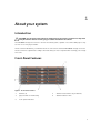
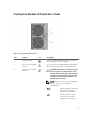
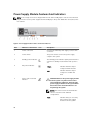
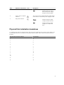
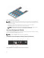
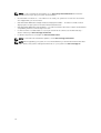
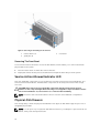
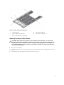
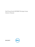
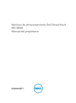
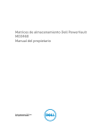
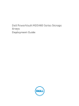
Dell PowerVault MD3060e Storage Enclosure
Owner's Manual
Regulatory Model: E08J Series
Regulatory Type: E08J001
Notes, Cautions, and Warnings
NOTE: A NOTE indicates important information that helps you make better use of your computer.
CAUTION: A CAUTION indicates either potential damage to hardware or loss of data and tells you
how to avoid the problem.
WARNING: A WARNING indicates a potential for property damage, personal injury, or death.
Copyright © 2014 Dell Inc. All rights reserved. This product is protected by U.S. and international copyright and
intellectual property laws. Dell™ and the Dell logo are trademarks of Dell Inc. in the United States and/or other
jurisdictions. All other marks and names mentioned herein may be trademarks of their respective companies.
2014 - 11
Rev. A01
Contents
1 About your system................................................................................................ 5
Introduction........................................................................................................................................... 5
Front-Panel Features ............................................................................................................................ 5
Front-Panel Indicators ......................................................................................................................... 6
Back-Panel Features..............................................................................................................................8
Cooling Fan Module LED Indicator Codes...........................................................................................9
Power Supply Module Features And Indicators ................................................................................ 10
Physical Disk Installation Guidelines................................................................................................... 11
Enclosure Management Module.........................................................................................................12
MD3060e Enclosure Management Module Features And Indicators......................................... 12
Storage Enclosure Thermal Shutdown......................................................................................... 13
Related Documentation...................................................................................................................... 13
2 Installing and removing system components............................................... 15
Recommended Tools.......................................................................................................................... 15
Removing And Installing The Front Bezel...........................................................................................15
Installing The Front Bezel.............................................................................................................. 15
Removing The Front Bezel............................................................................................................16
Service Action Allowed Indicator LED................................................................................................ 16
Physical-Disk Drawers.........................................................................................................................16
Opening The Physical-Disk Drawer.............................................................................................. 17
Closing The Physical-Disk Drawer................................................................................................18
Removing The Physical-Disk Drawer........................................................................................... 19
Installing The Physical-Disk Drawer............................................................................................. 20
Physical Disks.......................................................................................................................................21
Removing A Physical Disk From A Physical-Disk Carrier............................................................. 21
Installing A Physical Disk In A Physical-Disk Carrier.................................................................... 23
Removing A Physical Disk From A Physical-Disk Drawer............................................................24
Installing A Physical Disk In A Physical-Disk Drawer....................................................................25
SAS Chain Cables................................................................................................................................ 25
Removing The SAS Chain Cable(s)............................................................................................... 26
Installing The SAS Chain Cable(s)................................................................................................. 27
Enclosure Management Modules.......................................................................................................28
Removing An Enclosure Management Module........................................................................... 28
Installing An Enclosure Management Module............................................................................. 29
Power Supplies....................................................................................................................................29
Removing A Power Supply Module.............................................................................................. 30
Installing A Power Supply Module.................................................................................................31
Cooling Fan Modules.......................................................................................................................... 32
Removing A Cooling Fan Module.................................................................................................32
Installing A Cooling Fan Module...................................................................................................33
3 Troubleshooting your system.......................................................................... 34
Safety first—for you and your system.................................................................................................34
Troubleshooting External Connections............................................................................................. 34
Troubleshooting Power Supply Modules...........................................................................................34
Troubleshooting Enclosure Cooling Problems................................................................................. 35
Troubleshooting Physical Disks..........................................................................................................35
Troubleshooting A Wet Storage Enclosure........................................................................................36
4 Technical Specifications....................................................................................37
5 Getting help.........................................................................................................40
Locating your system service tag.......................................................................................................40
Contacting Dell................................................................................................................................... 40
Documentation feedback...................................................................................................................40
1
About your system
Introduction
CAUTION: See the Safety, Environmental, and Regulatory Information document for important
safety information before following any procedures listed in this document.
The MD3060e storage enclosure is a 4U rack-mounted system, capable of accommodating up to sixty
3.5 inch or 2.5 inch physical disks.
This document familiarizes you with the functions of the Dell PowerVault MD3060e storage enclosure.
The document is organized according to the tasks that you must complete after receiving your storage
enclosure.
Front-Panel Features
Figure 1. Front-Panel Features
1.
drawers (5)
2.
drawer release latches (2 per drawer)
3.
physical disk slot numbering
4.
drawer indicator LEDs
5.
front-panel indicators
5
Front-Panel Indicators
Figure 2. Front-Bezel Indicators
Figure 3. Front-Panel Indicators
6
Item
Indicator
Icon
Description
1
Power-on indicator
The power-on indicator lights green when at least
one power supply module is supplying power to
the storage enclosure.
2
Standby power indicator
The standby power indicator lights green when the
system is in standby mode and the main power is
off.
3
System identification
indicator
The system identification indicator lights white and
helps locate a particular enclosure within a rack.
4
Over temperature
indicator
The over temperature indicator lights amber when
the temperature of the system has reached an
unsafe condition.
5
Service action required
indicator (system)
The Service action required indicator lights amber
when there is a fault in one of the components in
the system.
6
Service action allowed
indicator (system)
CAUTION: Remove the physical disk drawer
from the system only if the Service action
allowed indicator lights blue. Removing the
physical disk drawer from the system when
the Service action allowed indicator is off
may damage the system.
NOTE: The Service action allowed indicator
LED is not used in server attached
configurations.
7
Service action required
indicator (drawer)
Blue
Indicates that you can safely
remove the physical disk
drawer from the system.
Off
Indicates that you cannot
remove the physical disk
drawer from the system.
Amber
Indicates that the cable is
attached and at least one
lane has a link up status, but
at least one lane has a link
down status.
Off
Indicates that:
•
•
•
No cable is attached.
A cable is attached, and
all lanes have a link up
status.
A cable is attached, and
all lanes have a link down
status.
7
Item
Indicator
8
Drive activity indicator
Icon
Description
NOTE: The associated physical disk is
indicated by a number (0 to 11) that is
displayed above the drive activity indicator.
For example, for physical disk 2 on the
physical disk drawer, the drive activity
indicator has 2 displayed above the drive
activity indicator.
Green
Indicates that power is on
and the physical disk is
operating normally.
Blinks green
Indicates I/O activity for that
physical disk.
Off
Indicates that there is no
power reaching the drive or
a drive is not installed.
Back-Panel Features
Figure 4. Back-Panel Features
1.
cooling fan modules (2)
3.
power supply modules (2)
8
2.
enclosure management modules (2)
Cooling Fan Module LED Indicator Codes
Figure 5. Cooling Fan Module Indicators
Item
Indicator
Icon
Description
1
Power indicator
The power indicator lights green when power to
the cooling fan module is available.
2
Service action required
indicator
The Service action required indicator lights amber
when there is a fault in the cooling fan module.
3
Service action allowed
indicator
CAUTION: Remove the cooling fan module
from the system only if the Service action
allowed indicator lights blue. Removing the
cooling fan module from the system when
the Service action allowed indicator is off
may damage the system.
NOTE: The Service action allowed indicator
LED is not used in server attached
configurations.
Blue
Indicates that you can safely
remove the cooling fan
module from the system.
Off
Indicates that you cannot
remove the cooling fan
module from the system.
9
Power Supply Module Features And Indicators
NOTE: Your storage enclosure is shipped with two IEC C19 to C20 jumper cords. Connect the C19
plug to the enclosure’s power supplies and the C20 plug to the power distribution unit (PDU) in the
rack cabinet.
Figure 6. Power Supply Module Features and Status Indicators
Item
Indicator or Connector
1
Power connector
Connect the external power supply source to this
connector.
2
Power switch
The power switch controls the power supply
output to the system.
3
Standby power indicator
The standby power indicator lights green when the
system is in standby mode and the main power is
off.
4
DC power indicator
5
Icon
Description
Green
Indicates that DC output
voltage is within the limit.
Off
Indicates that DC output
voltage is not within the
limit.
Service action allowed
indicator
CAUTION: Remove the power supply module
from the system only if the Service action
allowed indicator lights blue. Removing the
power supply module from the system when
the Service action allowed indicator is off
may damage the system.
NOTE: The Service action allowed indicator
LED is not used in server attached
configurations.
Blue
10
Indicates that you can safely
remove the power supply
module from the system.
Item
Indicator or Connector
Icon
Description
Off
6
Service action required
indicator
7
AC power indicator
Indicates that you cannot
remove the power supply
module from the system.
The service action required indicator lights amber
when there is a fault in the power supply module.
Green
Indicates that AC output
voltage is within the limit.
Off
Indicates that AC output
voltage is not within the
limit.
Physical Disk Installation Guidelines
To maintain proper airflow, install physicals disks from left to right and front to back in each drawer. The
following table lists the slot numbers of the physical disks and the order in which the disks need to be
installed.
Physical Disk Installation Order
Slot Number
1
0
2
3
3
6
4
9
5
1
6
4
7
7
8
10
9
2
10
5
11
8
12
11
11
Figure 7. Slot Numbering on the Disk Drawer
NOTE: If you need to install less than 12 physical disks, you must follow the recommended physical
disk installation order. For example if you have to install only 7 disks, the order of installation should
be 0, 3, 6, 9, 1, 4, and 7.
•
A minimum of four disks must be installed in the front slots 0, 3, 6, and 9 of each drawer.
•
The MD3060e storage enclosure supports mixing of physical disk types.
NOTE: 3.5" 10k and 15k RPM SAS drives are not supported. For the latest drive support, refer to
Dell PowerVault MD3060e Support Matrix at: dell.com/powervaultmanuals.
Enclosure Management Module
Use the enclosure management modules to expand the storage capacity, by daisy-chaining your storage
enclosure with additional MD3060e storage enclosures.
NOTE: Hot-plug of MD3060e storage enclosure is not supported.
MD3060e Enclosure Management Module Features And Indicators
Figure 8. MD3060e Enclosure Management Module Features and Indicators
12
Item
Indicator, Button, or
Connector
Icon
Description
1
SAS IN port 0
For SAS connection of the storage enclosure to a server,
RAID controller, or another storage enclosure.
2
SAS IN port 1
For SAS connection of the storage enclosure to a server,
RAID controller, or another storage enclosure.
3
Serial debug port
Dell support only.
4
Telnet port
Dell support only.
5
SAS OUT port
For connection to additional storage enclosures.
6
Diagnostic LED
The numeric display consists of two seven-segment LEDs
that provide information about enclosure identification
and diagnostics.
7
Module power indicator
The module power indicator lights green when module
power is on.
8
Service action required
indicator (system)
The Service action required indicator lights amber when
there is a fault in one of the components in the system.
9
Service action allowed
indicator
CAUTION: Remove the expansion module from the
system only if the Service action allowed indicator
lights blue. Removing the expansion module from
the system when the Service action allowed
indicator is off may damage the system.
NOTE: The Service action allowed indicator LED is
not used in server attached configurations.
Blue
Indicates that you can safely
remove the expansion module
from the system.
Off
Indicates that you cannot remove
the expansion module from the
system.
Storage Enclosure Thermal Shutdown
The system automatically shuts down when system temperature exceeds the safe threshold.
Temperature threshold values determine the temperature at which shutdown occurs. These thresholds
cannot be changed. The system will attempt to auto-restart after returning to normal temperatures.
Related Documentation
WARNING: See the safety and regulatory information that shipped with your system. Warranty
information may be included within this document or as a separate document.
13
NOTE: For all PowerVault documentation, go to dell.com/powervaultmanuals and enter the
system Service Tag to get your system documentation.
•
Rack Installation Instructions — Describes how to install your system into a rack. This document is
also shipped with your rack solution.
•
Dell PowerVault MD3060e Storage Enclosure Deployment Guide — Provides information about
deploying the storage system in the direct attached architecture.
•
Dell PowerVault MD3060e Support Matrix — Provides information about the software and hardware
compatibility matrices for the storage enclosure.
•
For the full name of an abbreviation or acronym used in this document, see the Dell Glossary –
Version 2 Glossary at dell.com/support/manuals.
•
For Online Help Resource, navigate to dell.com/PVResources.
NOTE: For the latest documentation updates, check dell.com/support/manuals.
NOTE: When upgrading your system, it is recommended that you download and install the latest
BIOS, drivers, and systems management firmware on your system from dell.com/support.
14
Installing and removing system
components
2
Recommended Tools
You may need the following items to perform the procedures in this section:
•
#2 Phillips screwdriver
•
T8 and T15 Torx screwdrivers
•
Wrist grounding strap connected to ground
Removing And Installing The Front Bezel
Installing The Front Bezel
You must install the front bezel on the system to secure the disk drawers against accidental removal.
1.
Align the slots on the back of the bezel with the guide pins on the front of the chassis.
2.
Push the bezel toward the chassis until the bezel is seated properly and the release latches snap into
place.
15
Figure 9. Removing and Installing the Front Bezel
1.
release latches (2)
3.
guide pins (4)
2.
front bezel
Removing The Front Bezel
You must remove the front bezel to access the disk drawers, which enables you to remove and install
physical disks in the system.
1.
Press the release latch on either side of the front bezel.
2.
Keeping the release latches pressed, hold the bezel and pull the bezel away from the system.
Service Action Allowed Indicator LED
Each hot-swappable component on your storage enclosure has a Service action allowed indicator. The
Service action allowed indicator, indicates that a component can be safely removed from the storage
enclosure.
CAUTION: Never remove any hot-swappable component until the Service action allowed
indicator on the component lights blue. Removing a hot-swappable component with the Service
action allowed indicator off, can result in a loss of data and data availability.
NOTE: The Service action allowed indicator LED is not used in server attached configurations.
Physical-Disk Drawers
Each storage array contains five physical-disk drawers. Each physical-disk drawer supports up to 12 hotswappable physical disks.
NOTE: You can open only one physical-disk drawer at a time. If you attempt to open more than one
drawer, it may cause unexpected results.
16
Figure 10. Inside the Physical-Disk Drawer
1.
release latch (2)
2.
physical-disk bay (12)
3.
physical-disk connector (12)
4.
SAS cable connection (2)
5.
physical-disk drawer release tab (2)
Opening The Physical-Disk Drawer
CAUTION: Many repairs may only be done by a certified service technician. You should only
perform troubleshooting and simple repairs as authorized in your product documentation, or as
directed by the online or telephone service and support team. Damage due to servicing that is
not authorized by Dell is not covered by your warranty. Read and follow the safety instructions
that came with the product.
1.
Remove the front bezel.
2.
Hold and rotate the release latches away from the system until the physical-disk drawer is free from
its slot.
3.
Hold the physical-disk drawer and pull it away from the chassis.
17
Figure 11. Opening and Closing the Physical-Disk Drawer
1.
physical-disk drawer
2.
release latches (2)
Closing The Physical-Disk Drawer
CAUTION: Many repairs may only be done by a certified service technician. You should only
perform troubleshooting and simple repairs as authorized in your product documentation, or as
directed by the online or telephone service and support team. Damage due to servicing that is
not authorized by Dell is not covered by your warranty. Read and follow the safety instructions
that came with the product.
1.
Hold the physical-disk drawer and push it into the chassis until it is seated properly.
2.
Hold and rotate the release latches toward the system until the release latches lock into place.
3.
Install the front bezel.
18
Removing The Physical-Disk Drawer
CAUTION: Many repairs may only be done by a certified service technician. You should only
perform troubleshooting and simple repairs as authorized in your product documentation, or as
directed by the online or telephone service and support team. Damage due to servicing that is
not authorized by Dell is not covered by your warranty. Read and follow the safety instructions
that came with the product.
1.
Prepare the physical-disk drawer for removal by stopping all input and output to the storage
enclosure.
2.
Remove the front bezel.
3.
Remove both the SAS cable chains from the back of the chassis.
4.
Open the physical-disk drawer.
CAUTION: Do not try to remove more than one drawer at a time. Ensure that you insert the
drawer that is out completely before pulling out another drawer.
NOTE: Note and save the location of the physical disks before removing the physical disks from
the physical-disk drawer.
NOTE: The physical-disk drawers are not hot-swappable. Replacing a physical-disk drawer
causes all of the physical disks in the replaced drawer to be unavailable to the Enclosure
Management Modules (EMM) in the storage subsystem.
5.
Remove all the physical disks from the disk drawer.
6.
Slide the physical-disk drawer out until the release tab on each side of the disk drawer is visible.
7.
Pull the release tab toward the front of the system to release the physical-disk drawer from the
chassis and pull the physical-disk drawer out of the chassis.
19
Figure 12. Removing and Installing the Physical-Disk Drawer
1.
physical-disk drawer
2.
release tabs (2)
Installing The Physical-Disk Drawer
CAUTION: Many repairs may only be done by a certified service technician. You should only
perform troubleshooting and simple repairs as authorized in your product documentation, or as
directed by the online or telephone service and support team. Damage due to servicing that is
not authorized by Dell is not covered by your warranty. Read and follow the safety instructions
that came with the product.
1.
Align the physical-disk drawer with the slot on the chassis.
2.
Slide the physical-disk drawer into the chassis until it is seated properly and the release tabs snap into
place.
3.
Install the physical disks row wise into the physical-disk drawer.
NOTE: Using the note that you saved while removing the physical-disk drawer, install the
physical disks to the same location in the physical-disk drawer that they were in.
4.
Close the physical-disk drawer.
5.
Install the SAS chain cables.
NOTE: Make sure all the SAS chain cables are firmly connected to all the drawers.
20
6.
Install the front bezel.
Physical Disks
Your system supports up to sixty 2.5 inch or 3.5 inch SAS and nearline SAS physical disks and up to 25 2.5
inch SAS SSDs per enclosure.
NOTE: For more details on the latest supported physical disks, physical disk types, and supported
quantities, refer to the MD3060e Storage Enclosure Support Matrix.
Removing A Physical Disk From A Physical-Disk Carrier
CAUTION: Many repairs may only be done by a certified service technician. You should only
perform troubleshooting and simple repairs as authorized in your product documentation, or as
directed by the online or telephone service and support team. Damage due to servicing that is
not authorized by Dell is not covered by your warranty. Read and follow the safety instructions
that came with the product.
1.
Pull the edge of the physical-disk carrier away from the physical disk until the pins on the physicaldisk carrier disengage from the slots on one side of the physical-disk.
2.
Hold the physical disk and angle the physical disk out of the physical-disk carrier.
21
Figure 13. Removing and Installing the 2.5 Inch Physical Disk in a 2.5 Inch Physical-Disk Carrier
22
1.
2.5 inch physical drive cage
2.
guide pins (4)
3.
release handle
4.
holes on physical disk (4)
5.
carrier for 2.5 inch physical disk
6.
2.5 inch physical disk
Figure 14. Removing and Installing the 3.5 Inch Physical Disk in a 3.5 Inch Physical-Disk Carrier
1.
3.5 inch physical disk
2.
release handle
3.
slots on physical disk (4)
4.
side guide pin (4)
5.
carrier for 3.5 inch physical disk
6.
bottom guide pins (2). Removed from
newer carriers
Installing A Physical Disk In A Physical-Disk Carrier
CAUTION: Many repairs may only be done by a certified service technician. You should only
perform troubleshooting and simple repairs as authorized in your product documentation, or as
directed by the online or telephone service and support team. Damage due to servicing that is
not authorized by Dell is not covered by your warranty. Read and follow the safety instructions
that came with the product.
1.
Angle the physical disk into the physical-disk carrier.
2.
Align the holes on one side (and if applicable, on the bottom) of the physical disk with the pins on the
corresponding side of the physical-disk carrier.
3.
Push out the edges on the other side of the physical-disk carrier, so that the holes on the other side
of the physical disk align with the pins on the physical-disk carrier and snap the physical-disk carrier
on to the physical disk.
23
Removing A Physical Disk From A Physical-Disk Drawer
CAUTION: Many repairs may only be done by a certified service technician. You should only
perform troubleshooting and simple repairs as authorized in your product documentation, or as
directed by the online or telephone service and support team. Damage due to servicing that is
not authorized by Dell is not covered by your warranty. Read and follow the safety instructions
that came with the product.
1.
Remove the front bezel.
2.
Identify the physical-disk drawer in which the faulty physical disk is installed.
3.
Open the physical-disk drawer.
4.
Identify and locate the faulty physical disk in the physical-disk drawer.
5.
Press the release tab to disengage the physical-disk carrier handle.
6.
Rotate the physical-disk carrier handle upward to disengage the physical disk from its connector.
7.
Hold the physical-disk carrier handle and lift the physical disk away from the system.
Figure 15. Removing and Installing the Physical Disk in the Physical-Disk Drawer
24
1.
physical disk
2.
physical-disk carrier handle
3.
physical-disk connector
4.
notches (2)
5.
raised buttons (2)
6.
physical-disk carrier
7.
release tabs (12)
Installing A Physical Disk In A Physical-Disk Drawer
CAUTION: Many repairs may only be done by a certified service technician. You should only
perform troubleshooting and simple repairs as authorized in your product documentation, or as
directed by the online or telephone service and support team. Damage due to servicing that is
not authorized by Dell is not covered by your warranty. Read and follow the safety instructions
that came with the product.
1.
Rotate the physical-disk carrier handle upward to the vertical position.
2.
Align the two raised buttons with the notches on the physical-disk drawer, lower the physical disk
into the slot in the physical-disk drawer.
NOTE: Ensure that you install the physical disk from left to right and from front to back.
3.
Rotate the handle downward until the physical disk is properly seated in the connector and the
physical-disk carrier handle snaps into place.
4.
Close the physical-disk drawer.
5.
Install the front bezel.
SAS Chain Cables
There are two SAS cable chains on each side of the physical-disk drawer that connects the physical disks
installed in the physical-disk drawer to the midplane.
•
The connector on each SAS chain cable that connects to the physical-disk drawer is oriented
horizontally.
•
The connector on each SAS chain cable that connects to the midplane is oriented vertically.
Figure 16. SAS Chain Cable Features
1.
SAS cable connector on the physical-disk
drawer (oriented horizontally)
3.
SAS chain cable (two per physical-disk drawer)
2.
SAS cable connector to the midplane
(oriented vertically)
25
Removing The SAS Chain Cable(s)
CAUTION: Many repairs may only be done by a certified service technician. You should only
perform troubleshooting and simple repairs as authorized in your product documentation, or as
directed by the online or telephone service and support team. Damage due to servicing that is
not authorized by Dell is not covered by your warranty. Read and follow the safety instructions
that came with the product.
1.
Remove the cooling fan module from one side on the back of the chassis.
CAUTION: If you are hot swapping the SAS cable chains, ensure that you complete the
procedure on one side within ten minutes to avoid over heating of the storage enclosure.
CAUTION: Ensure that you are removing the SAS cable chain for the failed physical-disk
drawer. Removing the SAS cable chain for the incorrect physical-disk drawer causes loss of
data access and causes virtual disks to appear degraded in the MD Storage Manager.
2.
Locate and identify the SAS chain cables for the failed physical-disk drawer.
3.
To remove the chain cable mounting bracket from the midplane, insert your finger into the release
tab (oriented vertically), and pull the mounting bracket completely out of the storage enclosure.
4.
To remove the chain cable mounting bracket from the physical disk drawer, insert your finger into
the release tab (oriented horizontally), and pull the mounting bracket completely out of the storage
enclosure.
5.
Install the cooling fan module.
6.
Repeat the above mentioned steps for the SAS cable chain on the other side.
26
Figure 17. Removing and Installing the SAS Chain Cable(s)
1.
left cooling fan module bay
2.
right cooling fan module bay
3.
SAS cable connector on the midplane
(two per physical disk drawer)
4.
SAS cable connector to the midplane
(oriented vertically)
5.
SAS chain cable (two per physical disk
drawer)
6.
release tab (oriented horizontally)
7.
SAS cable connector to the physical-disk
drawer (oriented horizontally)
8.
SAS cable connector on the physicaldisk drawer (oriented horizontally)
Installing The SAS Chain Cable(s)
CAUTION: Many repairs may only be done by a certified service technician. You should only
perform troubleshooting and simple repairs as authorized in your product documentation, or as
directed by the online or telephone service and support team. Damage due to servicing that is
not authorized by Dell is not covered by your warranty. Read and follow the safety instructions
that came with the product.
1.
Remove the cooling fan module from one side on the back of the chassis.
27
CAUTION: If you are hot swapping the SAS cable chains, ensure that you complete the
procedure on one side within ten minutes to avoid over heating of the storage enclosure.
2.
Locate and identify the SAS chain cables for the new physical-disk drawer.
3.
Connect the chain cable mounting bracket (oriented horizontally) to the physical-disk drawer.
4.
Connect the chain cable mounting bracket (oriented vertically) to the midplane.
5.
Install the cooling fan module.
6.
Repeat the above mentioned steps for the SAS cable chain on the other side.
Enclosure Management Modules
Removing An Enclosure Management Module
CAUTION: Many repairs may only be done by a certified service technician. You should only
perform troubleshooting and simple repairs as authorized in your product documentation, or as
directed by the online or telephone service and support team. Damage due to servicing that is
not authorized by Dell is not covered by your warranty. Read and follow the safety instructions
that came with the product.
CAUTION: To avoid damage to the sensitive EMI contacts on the module, do not stack the
modules.
1.
Identify and locate the enclosure management module that you want to replace.
2.
Disconnect the cables connected to the RAID controller module, enclosure management module, or
server.
3.
Push down on the release tab and pull the release lever away from the chassis.
4.
Hold the release lever and pull the module away from the chassis.
28
Figure 18. Removing and Installing an Enclosure Management Module
1.
enclosure management module
3.
release tab
2.
release lever
Installing An Enclosure Management Module
CAUTION: Many repairs may only be done by a certified service technician. You should only
perform troubleshooting and simple repairs as authorized in your product documentation, or as
directed by the online or telephone service and support team. Damage due to servicing that is
not authorized by Dell is not covered by your warranty. Read and follow the safety instructions
that came with the product.
1.
Insert the enclosure management module into the bay until it seats into place.
2.
Push the release lever toward the chassis until it clicks into place.
3.
Connect all the cables to the enclosure management module.
Power Supplies
Your system supports two hot-swappable 1755 W power supply modules.
29
When two identical power supplies are installed, the power supply configuration is redundant. In
redundant mode, power is supplied to the system equally from both power supplies to maximize
efficiency.
When one power supply module is removed or has failed, the power supply configuration is nonredundant. Power is supplied to the system only by a single power supply module.
CAUTION: Do not plug the enclosure into a standard power outlet. Your storage enclosure is
shipped with two IEC C19 to C20 jumper cables. Connect the C19 plug to the enclosure’s power
supplies and the C20 plug to the power distribution unit (PDU) in the rack cabinet. For power
redundancy, split the power connections from each enclosure into separate PDUs and connect
the PDUs to external power receptacles on different circuits. The enclosure supports only 200 V
to 240 V input sources.
Removing A Power Supply Module
CAUTION: Many repairs may only be done by a certified service technician. You should only
perform troubleshooting and simple repairs as authorized in your product documentation, or as
directed by the online or telephone service and support team. Damage due to servicing that is
not authorized by Dell is not covered by your warranty. Read and follow the safety instructions
that came with the product.
CAUTION: The system requires one power supply module for normal operation. Remove and
replace only one power supply at a time in a system that is powered on.
1.
Identify and locate the faulty power supply module.
NOTE: The Service action required indicator lights amber when there is a fault in the power
supply module.
2.
Disconnect the power cable from the power source and the power supply module you intend to
remove and remove the cables from the cable securing strap.
3.
Pull and rotate the two release levers away from the chassis until the power supply module is free
from the slot.
4.
Hold the power supply module and slide the power supply out of the chassis.
30
Figure 19. Removing and Installing the power supply module
1.
power supply
2.
release latch (2)
Installing A Power Supply Module
CAUTION: Many repairs may only be done by a certified service technician. You should only
perform troubleshooting and simple repairs as authorized in your product documentation, or as
directed by the online or telephone service and support team. Damage due to servicing that is
not authorized by Dell is not covered by your warranty. Read and follow the safety instructions
that came with the product.
Ensure that the power switch on the power supply module that you are installing, is in the off position.
1.
Slide the new power supply module into the chassis until the power supply module is fully seated.
2.
Rotate both the release lever toward the chassis until the power supply module locks into place.
3.
Connect the power cable to the power supply module and plug the cable into a power outlet.
CAUTION: When connecting the power cable, secure the cable with the cable securing
bracket.
NOTE: When installing or hot-swapping a new power supply module, allow several seconds for
the system to recognize the power supply module and determine its status. The power-supply
status indicator turns green to signify that the power supply module is functioning properly.
31
Cooling Fan Modules
Your system supports two hot-swappable cooling fan modules.
Removing A Cooling Fan Module
CAUTION: Many repairs may only be done by a certified service technician. You should only
perform troubleshooting and simple repairs as authorized in your product documentation, or as
directed by the online or telephone service and support team. Damage due to servicing that is
not authorized by Dell is not covered by your warranty. Read and follow the safety instructions
that came with the product.
CAUTION: The cooling fans are hot-swappable. To maintain proper cooling while the system is
on, replace only one fan at a time.
NOTE: The procedure for removing each cooling fan module is identical.
Make sure that the Service action allowed indicator lights blue before you remove the cooling fan
module. For more information, see Cooling Fan Module LED Indicator Codes.
NOTE: The Service action allowed indicator LED is not used in server attached configurations.
1.
Identify and locate the failed cooling fan module.
CAUTION: Remove the cooling fan module from the system only if the Service action allowed
indicator lights blue. Removing the cooling fan module from the system when the Service
action allowed indicator is off may damage the system.
NOTE: The Service action allowed indicator LED is not used in server attached configurations.
2.
Press the cooling fan module release latch to release the cooling fan module handle.
3.
Rotate the cooling fan module handle away from the system, until the cooling fan module is released
from the slot.
4.
Holding the cooling fan module release handle, pull the cooling fan module away from the chassis.
32
Figure 20. Removing and Installing the Cooling Fan Module
1.
cooling fan module release latch
3.
cooling fan module
2.
cooling fan module handle
Installing A Cooling Fan Module
CAUTION: Many repairs may only be done by a certified service technician. You should only
perform troubleshooting and simple repairs as authorized in your product documentation, or as
directed by the online or telephone service and support team. Damage due to servicing that is
not authorized by Dell is not covered by your warranty. Read and follow the safety instructions
that came with the product.
1.
Align the cooling fan module with the slot on the back of the chassis.
2.
Slide the cooling fan module into the slot until it is properly seated.
3.
Rotate the cooling fan module handle toward the chassis until the cooling fan module handle locks
in place.
CAUTION: For proper cooling of the storage enclosure, ensure that all the cooling fans are
operational at all times.
33
Troubleshooting your system
3
Safety first—for you and your system
CAUTION: Many repairs may only be done by a certified service technician. You should only
perform troubleshooting and simple repairs as authorized in your product documentation, or as
directed by the online or telephone service and support team. Damage due to servicing that is
not authorized by Dell is not covered by your warranty. Read and follow the safety instructions
that came with the product.
Troubleshooting External Connections
•
Verify that the cables are connected to the correct ports before troubleshooting any external devices.
For the location of the back-panel connectors on your storage enclosure, see Back-Panel Features.
•
Ensure that all the cables are securely attached to the external connectors on your enclosure.
•
For information on cabling, see the Deployment Guide for your storage enclosure at dell.com/
support/manuals.
Troubleshooting Power Supply Modules
CAUTION: Many repairs may only be done by a certified service technician. You should only
perform troubleshooting and simple repairs as authorized in your product documentation, or as
directed by the online or telephone service and support team. Damage due to servicing that is
not authorized by Dell is not covered by your warranty. Read and follow the safety instructions
that came with the product.
CAUTION: It is recommended that you turn off the host server before turning off the enclosure to
prevent loss of data.
1.
Locate the faulty power supply and determine the status of the LEDs.
•
If the AC power LED is not lit, check the power cord and power source into which the power
supply module is plugged.
– Connect another device to the power source to verify if it is working.
– Connect the cable to a different power source.
– Replace the power cable. If the problem is not resolved, see Getting Help.
34
•
If the DC power LED is not lit, verify that the power switch is turned on. If the power switch is
turned on, see step 2.
•
If the power supply module’s fault indicator is lit, see Getting Help.
CAUTION: Power supply modules are hot-swappable. The enclosure can operate on a single
power supply module; however both modules must be installed to ensure proper cooling. A
single power supply module can be removed from a powered-on enclosure for a maximum
period of five minutes. Beyond that time, the enclosure may automatically shut down to
prevent damage.
2.
Reseat the power supply module by removing and reinstalling it.
NOTE: After installing a power supply module, allow several seconds for the enclosure to
recognize the power supply module and to determine if it is working properly.
If the problem is not resolved, see Getting Help.
Troubleshooting Enclosure Cooling Problems
CAUTION: Many repairs may only be done by a certified service technician. You should only
perform troubleshooting and simple repairs as authorized in your product documentation, or as
directed by the online or telephone service and support team. Damage due to servicing that is
not authorized by Dell is not covered by your warranty. Read and follow the safety instructions
that came with the product.
Ensure that none of the following conditions exist:
•
Ambient temperature is too high, as a physical-disk drawer is left open for an extended period.
•
External airflow is obstructed.
•
The cooling fan module is removed or has failed.
If the problem is not resolved, see Getting Help.
Troubleshooting Physical Disks
CAUTION: Many repairs may only be done by a certified service technician. You should only
perform troubleshooting and simple repairs as authorized in your product documentation, or as
directed by the online or telephone service and support team. Damage due to servicing that is
not authorized by Dell is not covered by your warranty. Read and follow the safety instructions
that came with the product.
1.
Check the physical disk to ensure that the most current version of the firmware is installed, if
possible. For more information, see the Dell PowerVault MD3060e Storage Enclosure Administrator's
Guide at dell.com/powervaultmanuals.
2.
Remove the physical disk from the system.
NOTE: You must ensure that you check the physical disk indicators before removing the faulty
physical disk from the system.
3.
Check the physical disks and the midplane to ensure that the connectors are not damaged.
4.
Reinstall the physical disk.
5.
If the problem is not resolved, replace the failed physical disk.
If the problem persists, see Getting Help.
35
Troubleshooting A Wet Storage Enclosure
CAUTION: Many repairs may only be done by a certified service technician. You should only
perform troubleshooting and simple repairs as authorized in your product documentation, or as
directed by the online or telephone service and support team. Damage due to servicing that is
not authorized by Dell is not covered by your warranty. Read and follow the safety instructions
that came with the product.
1.
Turn off the enclosure and disconnect all the cables.
2.
Remove the following components from the enclosure:
•
Physical disks
•
Power supply modules
3.
• Cooling fan modules
Let the system dry thoroughly for at least 24 hours.
4.
Reinstall the components you removed in step 2.
5.
Connect all the cables and turn on the enclosure.
36
Technical Specifications
4
Physical Disks
Physical disks
Up to sixty 3.5 inch or 2.5 inch SAS or nearline SAS
physical disks or 2.5 inch SAS SSDs
NOTE: For more details on the latest supported
physical disks, physical disk types, and
supported quantities, refer to the MD3060e
Storage Enclosure Support Matrix.
Enclosure Management Modules
Dell PowerVault MD3060e storage enclosures
Supports 60 physical disks
Redundant path connectivity provides redundant
data paths to each hard drive
SAS connectors
Two SAS ports (marked IN) to connect to host
server(s) or to expand the MD series storage
dense enclosure
Third SAS port labelled OUT. Port can be used for
further storage enclosure expansion or storage
enclosure fault tolerance.
NOTE: SAS connectors are SFF-80644
compliant.
Serial connector (debug port)
Six pin port
NOTE: For technical support use only.
Power
AC power supply (per power supply)
Wattage
1755 W
Heat dissipation (maximum)
5988 BTU/hr
NOTE: Heat dissipation is calculated
using the power supply wattage rating.
The heat dissipation values are for the
entire system which includes chassis and
two EMMs.
Voltage
220 V AC, autoranging, 50 Hz/60 Hz
37
Power
NOTE: This system is also designed to be
connected to IT power systems with a
phase to phase voltage not exceeding
230 V.
Environmental
NOTE: For additional information about environmental measurements for specific system
configurations, see dell.com/environmental_datasheets.
Temperature
Operating
Continuous operation: 10 °C to 35 °C (50 °F to 95 °F) at
20% to 80% relative humidity (RH), with 26 °C
maximum dew point. De-rate maximum allowable dry
bulb temperature at 1 °C/300 m (1 °F per 550 ft) above
900 m (2952.75 ft).
NOTE: For information on supported expanded
operating temperature range and configurations,
see the Owner's Manual at dell.com/support/
manuals.
Storage
–40 °C to 65 °C (–40 °F to 149 °F) with a maximum
temperature gradation of 20 °C per hour
Relative humidity
Operating
20% to 80% (noncondensing) with maximum humidity
gradation of 10% per hour
Storage
5% to 95% at a maximum wet bulb temperature of 38
°C (100.4 °F)
Maximum vibration
Operating
0.26 Grms at 5 Hz to 350 Hz in operational orientation
Storage
1.88 Grms at 10 Hz to 500 Hz for 15 minutes (all six sides
tested)
Maximum shock
Operating
One shock pulse in the positive z axis of the system at
31 G for 2.6 ms in the operational orientation
Storage
Six consecutively executed shock pulses in the positive
and negative x, y, and z axes (one pulse on each side of
the system) at 71 G for up to 2 ms
Six consecutively executed shock pulses in the positive
and negative x, y, and z axes (one pulse on each side of
the system) of 22 G faired square wave pulse with
velocity change at 200 inches/second (508
centimeters/second)
38
Environmental
Altitude
Operating
Maximum 3000 m (9,842 ft)
Storage
Maximum 12192 m (40,000 ft)
Airborne contaminant level
Class
G1 as defined by ISA-S71.04-1985
39
Getting help
5
Locating your system service tag
Your system is identified by a unique Express Service Code and Service Tag number. The Express Service
Code and Service Tag are found on the front of a physical DR Series system by pulling out the
information tag. This can also be found on the support tab in the GUI. This information is used by Dell to
route support calls to the appropriate personnel.
Contacting Dell
Dell provides several online and telephone-based support and service options. If you do not have an
active Internet connection, you can find contact information on your purchase invoice, packing slip, bill,
or Dell product catalog. Availability varies by country and product, and some services may not be
available in your area. To contact Dell for sales, technical support, or customer-service issues:
1.
Go to dell.com/support.
2.
Select your country from the drop-down menu on the bottom right corner of the page.
3.
For customized support:
a. Enter your system Service Tag in the Enter your Service Tag field.
b. Click Submit.
The support page that lists the various support categories is displayed.
4.
For general support:
a. Select your product category.
b. Select your product segment.
c. Select your product.
The support page that lists the various support categories is displayed.
Documentation feedback
If you have feedback for this document, write to [email protected]. Alternatively, you
can click on the Feedback link in any of the Dell documentation pages, fill out the form, and click Submit
to send your feedback.
40