1
Indiana University Purdue University – Fort Wayne
Department of Engineering
ECE 406
Capstone Senior Design Project
Report #2
Project Title:
HVAC Data Measurement and Acquisition Device
Team Members:
Ross Blauvelt
EE
Yaya Mahamat
EE
Gabriela Mosquera
EE
Christopher Yocum
EE
Faculty Advisors:
Dr. Carlos Pomalaza-Ráez
Date:
May 2, 2014
Table of Contents
ACKNOWLEDGEMENTS ........................................................................................................................ 3
ABSTRACT ............................................................................................................................................ 4
SECTION I: PROBLEM STATEMENT ........................................................................................................ 5
1. PROBLEM STATEMENT ................................................................................................................................ 6
2. REQUIREMENTS & SPECIFICATIONS ............................................................................................................... 6
3. GIVEN PARAMETERS AND ADAPTIONS ........................................................................................................... 7
4. DESIGN VARIABLES ..................................................................................................................................... 7
5. LIMITATIONS & CONSTRAINTS ...................................................................................................................... 7
SECTION II: SUBASSEMBLY DESIGNS ..................................................................................................... 8
1. COMPONENT DESIGN ............................................................................................................................... 10
a. Solid State Relay .............................................................................................................................. 10
b. Bluetooth Shield ............................................................................................................................... 10
c. MAX485 ............................................................................................................................................ 11
d. Arduino Mega ADK Microcontroller ................................................................................................ 12
2. SOFTWARE DEVELOPMENT ........................................................................................................................ 14
a. Establishing Initial Communication ................................................................................................. 14
b. Android - Arduino Flow Chart .......................................................................................................... 15
c. Procedure for Software Development .............................................................................................. 18
SECTION III: TESTING AND EVALUATION............................................................................................. 22
ENCLOSURE ASSEMBLY ................................................................................................................................. 23
COMPONENT INTEGRATION ........................................................................................................................... 23
INTEGRATION AND TEST RESULTS ................................................................................................................... 24
TEST PLAN .................................................................................................................................................. 26
FIELD TESTING ............................................................................................................................................ 33
SECTION IV: COST ANALYSIS/ESTIMATION ......................................................................................... 34
BILL OF MATERIALS ...................................................................................................................................... 35
COST ANALYSIS ........................................................................................................................................... 35
CONCLUSIONS.................................................................................................................................... 36
REFERENCES....................................................................................................................................... 37
APPENDICES....................................................................................................................................... 38
APPENDIX A: DMX2 CONTROL DIAGNOSTICS RS 485 ....................................................................................... 38
APPENDIX B: DMX2 DATA CONNECTOR RS485 (SCHEMATIC) ............................................................................ 43
APPENDIX C: DXM2 PHYSICAL DIMENSION & LAYOUT ...................................................................................... 44
APPENDIX D: PROGRAM LIST ......................................................................................................................... 45
Android Code ....................................................................................................................................... 45
Arduino Code ....................................................................................................................................... 69
2
Acknowledgements
The team would like to extend its sincere gratitude to the IPFW Engineering Department for the
sponsorship of this project, and to ClimateMaster for providing access to their equipment for
experimental purposes.
The team is also appreciative of the guidance received from Dr. Carlos Pomalaza-Ráez to meet with the
team each week to render his technical support, advice, and direction throughout the design process.
Along with Dr. Carlos Pomalaza-Raez the team would like to thank Dennis Harris of ClimateMaster who
has provided great information on acquiring data from the control board. Dennis Harris has many years
of experience in designing the control board DXM and his knowledge of it has become very valuable to
the team.
The team would like to thank the faculty, specifically Dr. Beomjin Kim, of the IPFW Department of
Computer Science for providing constructive criticism and guidance with programming during this
process.
Also, Todd Welch for his instrumental help and countless hours spent with the Java Script and
developing the App. Without his help, we’d still be at square one.
Lastly Donna for let us use her home and HVAC system for testing purposes and Pat from Geothermal
Sales and Services for setting up the meeting with Donna to finalize our project.
Thank you all!
3
Abstract
Currently the startup of commercial and industrial Heating Ventilating and Air Conditioning (HVAC)
systems require the physical presence of a technician to gather various data points required to confirm
the equipment is running correctly. This is accomplished by the use of specialized hardware. Once the
data is collected, the information is recorded using paper and pencil, which can be considered a
rudimentary process. ClimateMaster has HVAC systems that need to be tested to ensure safe, reliable,
and efficient cooling and heating operations. Some measurements must be acquired by hand; however
it is possible for other values to be collected and recorded electronically. Electronic forms of entered
data could be created using a handheld data collection device such as a laptop, smart phone, or tablet.
This project will attempt to eliminate the archaic method of paper and pencil and replace it with a new
digital approach. This will save the technician time and physical resources.
4
Section I: Problem Statement
5
1. Problem Statement
ClimateMaster is the market leader in designing and manufacturing Geothermal Heating Ventilation and
Air Conditioning systems. These systems require measurements, both physical and electrical, that are
recorded to ensure proper mechanical functionality. The various measurements are currently recorded
by hand and noted on a physical form. The HVAC system must be tested before turning over to the
owner to ensure safe, reliable, and efficient operation in cooling and heating mode. The measurement
procedure ensures that the system can properly cool and heat within desired time constraints. A
majority of the measurements are still recorded manually by hand but, with advancements in
technology, the values can now be recorded electronically.
It was proposed to create a method for the electronic submission of the test record which would be a
fast and efficient use of production resources; thus enabling engineering and technical support to easily
and quickly access the values that were recorded. Since the model, serial and part numbers are part of
the submission, defective parts can easily be cataloged and searchable. Such a method would cut down
on the physical time spent at the job site and ensure ease of access to data from each unit.
ClimateMaster would like a device that tests each unit in both heating and cooling mode to ensure
proper mechanical operation and record necessary data to confirm satisfactory operation. This all
should be done with minimal wires or connection to the unit. This new apparatus will be used by the
technician performing the startup of each unit and may be further implemented into each unit
manufactured in the future.
2. Requirements & Specifications
This system must be compatible with the pre-existing ClimateMaster unit and control board that will be
supplied. Requirements must be met to achieve the following goals.
The device should:
• Run the unit to ensure mechanical operation in Test Mode, Cooling Mode, and Heating Mode..
• Record the temperatures and voltages given by the control board.
• Record the M# and S# of each unit.
• Record any data into an electronic form.
• Communicate without wires with an Android based device such as a phone or tablet.
6
3. Given Parameters and Adaptions
The device is to use a technology readily accessible on a phone or tablet in which to interconnect with
wirelessly while maintaining a wired connection using the RS485 protocol that currently exists on the
DXM2 control board.
Originally, WIFI was considered but the necessity of internet independence made it a difficult option.
Also, a router would be needed with a power source further complicating the design (Ad-Hoc mode).
Infrastructure mode was a more viable option but was not possible on the Arduino system.
Phones and tablets have Bluetooth transmitters installed for operation of several devices such as
keyboards and headsets. A Bluetooth module was compatible and available to the Arduino system.
There was more literature on Android to Android devices available so Android to Arduino was more of a
challenge.
4. Design Variables
The final design concept, as well as more minor design details, is largely at the discretion of the design
team. Variables to be considered are the basis in which the device must work within a minimum set
standards.
•
•
•
•
Microcontroller series: Arduino Mega series – 2560 or ADK
Mobile device: Android based phone or tablet
Data Transfer: RS485 as pre-existing standard; Bluetooth adapter to mobile device
Software: Android version minimum – sets lowest standard for mobile device
Some earlier versions of Android are not as adaptable and for earlier devices must have code retroprogramming from newer versions back to the older versions to use certain features. This is the basis in
which a minimum Android version must have a standard as a design variable.
5. Limitations & Constraints
The limitations and constraints of the device were taken into account in order to properly design the
apparatus for ClimateMaster. Limitations and constraints are anything that could be potentially
inhibiting of the system. These were properly accounted for in order to adapt the system correctly.
Listed below are the parameters that are limiting factors.
•
•
•
•
Distance:
o Device must be able to work within 0-20 feet from HVAC unit with line of sight usually
Cost:
o IPFW will be sponsoring this project, therefore final cost of the project must not exceed a
budget of $400. It is important to keep tis in mind and design economically.
Reliability:
o The unit should work reliably as this will be the primary method for testing units and the
technician will most likely not bring alone the old design.
Voltage Range: Depends on the voltage source
o 265V 60Hz single phase
o 208-230V 60Hz single phase
o 208-230V 60Hz 3 phase
o 460V 60Hz 3 phase
7
Section II: Subassembly Designs
8
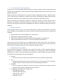
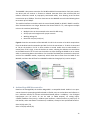
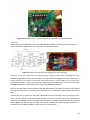
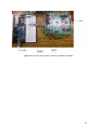
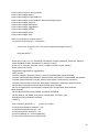
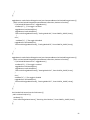
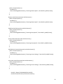
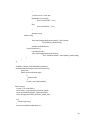
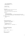
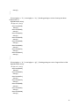
Figure 1: HVAC Design Content to be determined.
The area highlighted is what is to be contained in the device for test verification. The Microcontroller
Unit (1.) and Wireless Adapter (2.) are the physical parts of the device but do not show additional parts
used such as Max485 and solid-state relay modules. This section collects data from the control board via
RS485 and relays. It also accepts commands from the technician and processes them to access the
control board.
The lower set of items are Device & OS (3.), Application/Data Collection (4.) and Data Storage (5.), these
items belong on the technician side and are specifically the following: an Android device with Android
operating system, an application created to control the unit using Eclipse as the Android development
environment, an electronically generated form with Data sent from the DXM2 board to the Arduino,
which later sends it to the Android, which converts this data into PDF, finally a micro SD card that will be
used to store all of the generated PDF forms.
9
1. Component Design
a. Solid State Relay
The project needed a component that could switch the electrical line on and off (Line R
coming from the DXM2). A relay is a device that provides an electrical connection between two
or more points in response to a control signal. In addition, it has full isolation between the
control signal and the control board (DXM2). A solid state relay (SSR) was used for switching
on/off. A SSR is an electric switching device in which a small control signal controls a larger
voltage. It serves the same function as an electromechanical relay, but it is smaller, faster, and
has no moving parts when switching.
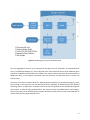
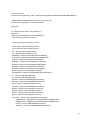
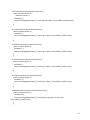
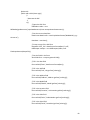
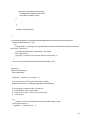
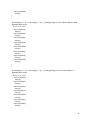
Omron’s G#VM-61A1 is MOS FET relay compact solid state relay with dielectric strength
of 2.5kVAC between I/O using optical isolation (LED). It is rated up to 50mA at 60VAC, so it can
handle the AC voltage that is coming from the DXM2 which is 24VAC. The control signal is rated
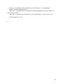
at 5V DC and requires at least 50 mA. Figure 2 shows the relay as well as its schematic. Pins 1
and 2 are the control LED terminals, pin 3 and 4 are the switching connections. Pin 3 is
connected to the load (Fan, Reversing Valve, or Compressor) and pin 4 is connected to the
24VAC (R from the DXM2).
Figure 2: Solid State Relay with schematic.
b. Bluetooth Shield
Next, the project required a change of the WIFI shield to a Bluetooth module due to lack of
point access of internet network in the premises. Therefore, a Bluetooth module became an
excellent choice in order to communicate with the DXM2 board. Hence, for the project the DFBluetooth V3 module was chosen due to its low cost and matched specifications for the
communication.
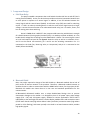
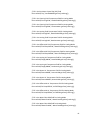
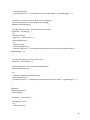
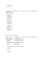
DF-BluetoothV3 Bluetooth module uses a unique double-board design aims to prevent
electrostatic damage to the module. It is designed to have 2 DC power input, wide voltage
supply (3.5V ~ 8V) and 3.3V power supply, suitable for various applications. STATE LINK is
indicated by a clear and bright LED which is used to display module status and connection status
(STATE state: Search state (high 104ms 342ms 2.9Hz cycle flicker) connection status (high 104ms
period 2s 0.5Hz flashing), LINK state: paired). It has built-in on-board antenna which provides
high quality signals.
10
Specifications
•
•
•
•
•
•
•
•
•
•
•
•
•
•
•
•
The Bluetooth chip: CSR BC417143
Bluetooth protocol: Bluetooth Specification v2.0 + EDR
USB Protocol: USB v1.1/2.0
Operating frequency: 2.4 ~ 2.48GHz unlicensed ISM band
Modulation: GFSK (Gaussian Frequency Shift Keying)
Transmit Power: ≤ 4dBm, Class 2
Transmission distance: 20 ~ 30m in free space
Sensitivity: ≤-84dBm at 0.1% BER
Transfer rate: Asynchronous: 2.1Mbps (Max) / 160 kbps; Synchronous:
1Mbps/1Mbps
Safety features: Authentication and encryption
Support profiles: Bluetooth serial port
Serial port baud rate: 4800 ~ 1382400 / N / 8 / 1 default: 9600
LED indicator: STATE: Search state (high 104ms 342ms 2.9Hz cycle flicker)
connection status (high 104ms cycle 2s 0.5Hz flashing), LINK Status: Always after
match
Input Voltage: +3.5 V ~ +8 V DC and 3.3V DC/50mA
Working temperature: -20 ℃ ~ +55 ℃
Module Size: 40 × 20 × 13mm
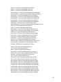
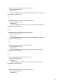
Figure 3: DF-Bluetooth V3 module.
c. MAX485
In order to interface the control board (DXM2) of the HVAC with the Microcontroller unit (MCU)
a MAX485 is necessarily required to achieve a half-duplex communication between the two
boards. Additionally, the DXM2 features a RS485 chip mounted on its board.
11
The MAX485 is low-power transceiver for RS-485 and RS-422 communication. Each part contains
one driver and one receiver. It features a reduced slew-rate driver that minimize EMI and
reduces reflections caused by improperly terminated cables, thus allowing error-free data
transmission up to 250kbps. The driver slew rates on the MAX485 are not limited allowing them
to transmit up to 2.5Mbps.
The module interfaces an Arduino with the control board (DXM2) to RS-485. RS485 is used for
Serial Communications over longer distances than direct RS232 or TTL, and supports multiple
units on the same bus (Multi-Drop).
•
•
•
•
Multiple Units can be connected to the same RS-485 wiring.
All Chip pins are brought out for proper controls
Working voltage: 5V
Board size: 44 (mm) x14 (mm)
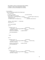
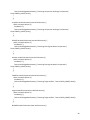
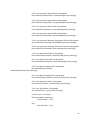
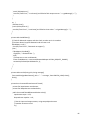
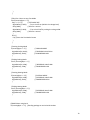
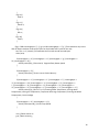
Figure 4 shows the connections of the MAX 485. Pin RO is the receiver or RX which acquire data
from the Arduino board connected to pin RX0. Pin DI is the transmitter or TX which is connected
to TX0 on the Arduino. Pin DE is driver enable or control enable that set what board is a
master/slave. If DE is high, it sets the Arduino as master, allowing the Arduino to transmit data
to the DXM2 board. If DE is low it sets the Arduino as slave allowing the DXM2 to act as master
which is transmitting data to the Arduino. Pins A and B of the DMX2 are connected to the pins A
and B of the MAX485 module, respectively which allow data to flow from the DXM2 to the
MAX485, and then data will flow from MAX485 to Arduino through pin RO, receiver output.
Figure 4: Max485 module.
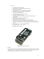
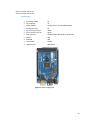
d. Arduino Mega ADK Microcontroller
Based on the Atmega2560, the Arduino Mega ADK is a compatible board. Arduino is an opensource electronics prototyping platform based on flexible, easy-to-use hardware and software. It
has a USB host interface to connect with Android based phones. In addition, it has 54 digital
input/output pins (of which 15 can be used as PWM outputs), 16 analog inputs,
4 UARTs (hardware serial ports), a 16 MHz crystal oscillator, a USB connection, a power jack, an
ICSP header, and a reset button. Furthermore, In addition, some pins have specialized functions:
Serial: 0 (RX) and 1 (TX)
Serial 1: 19 (RX) and 18 (TX)
12
Serial 2: 17 (RX) and 16 (TX)
Serial 3: 15 (RX) and 14 (TX).
Specifications
•
•
•
•
•
•
•
•
•
•
•
Operating voltage
Input voltage
Digital I/O pins
Analog Input Pins
DC current per I/O pin
DC current for 3.3V pin
Flash memory
SRAM
EEPROM
Clock speed
USB host chip
5V
7V
54(of which 15 provide PWM output)
16
40mA
50mA
256KB of which 8KB used by bootloader
8KB
4KB
16MHz
MAX3421E
Figure 5: Arduino Mega ADK.
13
2. Software Development
a. Establishing Initial Communication
Initiating communication between the Android device and the Arduino microcontroller is the most
essential function so it should be done first. Originally, WIFI was the desired concept due to officially
branded WIFI shield by Arduino. The WIFI shield as its support has certain shortcomings that were
undesirable to the needed criteria. There were adaptions but were excessive and costly. As a result,
Bluetooth was used as nearly all current phones and tablets come with Bluetooth for hands free talking
or keyboards (for tablets).
The WIFI technology on Arduino became a short coming in that it does not support WIFI Direct. Android
4+ supports the technology but there is documentation with other Android based devices. WIFI Direct
enables the ability to directly connect through Infrastructure Mode where no access point is needed.
Unfortunately, the Arduino WIFI shield is programmed to be routed through an AP, or access point, such
as a router. Its main function is for internet connectivity. This project is not using the internet for a
variety of reasons including that the facility may not have internet or access points available. Thus the
design would need to facilitate this requirement with adding a router which can become expensive and
complicated.
Two separate attempts were made to make a Bluetooth connection, a selectable device prompt on the
Android device and hardcoding the MAC address.
The device select prompt was based on the Bluetooth Chat Android example which contained several
“.jar” files that interacted. Very little programming notes were available to understand the interaction
between the files and screen “Activities.” The adaptation was successful in finding the Bluetooth module
attached to the Arduino but was unsuccessful in connecting due to permission requirements. The
computer science programmer was unable to assist in a resolution.
The method of using sample code on the internet was more successful. The code was all inside a single
“.jar” file. A demonstration that the communication was successful was performed using several
different color LEDs.
14
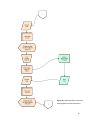
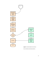
b. Android - Arduino Flow Chart
Figure 6a: Android Arduino Flow Chart.
Initialization and Cooling Mode.
15
Figure 6b: Android Arduino Flow Chart.
Heating Mode and Data Population.
16
Figure 6c: Android Arduino Flow Chart.
Form Verification and Disconnection.
17
c. Procedure for Software Development
The explain the software development it is important to know that this project’s software
implementation was divided into two main sections, the Arduino section and the Android section, as
shown in the two different columns in the Flowcharts from Figures 6a, 6b, and 6c.
Arduino:
In the Arduino code or sketch, there are two important parts that interface with the DXM2 and the
Android application.
Controlling the Board
The first part is to engage in test mode by using Serial1 port (TX1 and RX1) via Bluetooth. By sending a
letter “T” from the Android application via Bluetooth to the Arduino, a command called digitalWrite sets
the pin high in order to turn on the relay for the Fan. Eventually, such operation is repeated for the
other components (Compressor Y1 and the Reversing Valve). This operation is timed in the code in such
a way that it matched the routine done by the technician manually on the job site.
RS485 Communication
The second part is dedicated to request information from the DXM2 through the MAX485. Similarly, the
communication between the Arduino and the DXM2 is done using the Serial port (TX0 and RX0). The
data rate or the baud rate is set to be 9600 bit /s. In the same fashion, a variable is sent from the
Android application to the Arduino via Bluetooth to request a specific data from the DXM2.
Depending on which button has been pressed, a different, unique data packet is sent using the
Serial.write command. If the data packet is valid, the DXM2 will recognize it and respond with another
data packet, which will be read by the Arduino program using the Serial.read command. The Arduino will
read the incoming response packet byte by byte, and will assign different names to the bytes that
contain the important information which will undergo a concatenation process and then will be print
out using the Serial.print command to the Android side which will be explain in more detail next.
Android:
To be able to work with Android it was essential to connect via Bluetooth with the chosen Bluetooth
shield using Android’s official Bluetooth API. There are four major tasks necessary to be able to get
connectivity with Bluetooth: setting up Bluetooth, finding devices that are either paired or available in
the local area, connecting devices, and transferring data between devices. The BluetoothAdapter class
was used in the Android code since it represents the local Bluetooth radio on the phone. It performs
fundamental Bluetooth tasks, such as initiate device discovery, query a list of paired devices, instantiate
a device using a known MAC address, and create a server socket to listen for communications from
other devices. The BluetoothSocket class is used to both initiate an outgoing connection and to manage
the connection. Since the Bluetooth stack uses the Service Discovery Protocol (SDP) to gather
information about the devices and its parameters, the UUID (Universally Unique Identifier) was chosen
for our connection. Once the socket is connected, data can be exchanged with another Bluetooth device
via InputStream and OutputStream objects which read and send data in bytes. This allows the
application to send and receive data serially via the RFCOMM Bluetooth layer.
Once Bluetooth has been established, the Android development process can begin. An example code for
and Android application was found in the research phase of this project and used to start developing
this app. The found code was used to turn on and off an LED through Bluetooth using an Arduino
18
microcontroller (such code was completely adapted for our purposes). Now, the process of developing
our application is divided in three main subsections.
Sending Control Bytes to Arduino
The Android Application was created so that every time a control button has been pressed, a specific
byte is sent over Bluetooth to the Arduino, the Arduino will recognize a valid byte and perform
whichever specific function it is designed to perform. If we continue with the Test Mode example, the
Test Mode switch (once switched ON) will send a ‘T’ byte over Bluetooth to the Arduino, the Arduino
will read this byte through a variable called incomingByte and if it is a ‘T’ it will go through the test mode
procedure which consist on turning on and off the Fan three times and leaving it on.
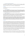
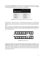
The Android Application that was created consisted on 30 simple buttons (28 for data and 2 for PDF), 2
toggle buttons (cooling and heating mode), 1 switch (test mode), 4 radio buttons (temperature and
pressure), and 23 text fields, these are all illustrated in Figure 7. All of the simple buttons, toggle
buttons, and the switch send control bytes as explained.
Figure 7: Screen shots of the developed application for Android devices.
19
Receiving Data from Arduino
Once the Arduino has collected all the data from the DXM2 board via RS485 protocol, all of the bytes
that contained data are sent to the Android using the Serial.print command in the Arduino code. This
data will be received in the Android and will be assigned to a text field, specifically the text field next to
the button that has been pressed. So if the Leav Water button is pressed, the data for the leaving water
temperature will be sent to the Android, and assigned to the Data textview field next to such button.
The same process applies to every Data button in the application.
Generating PDF
Next is to generate a pdf form where the technician will able to save the data acquired from the test
mode. This procedure is achieved successfully by utilizing the three main classes from the itextpdf which
are itextpdf.text.pdf.AcroFields, itextpdf.text.pdf.PdfReader, and itextpdf.text.pdf.pdfStramper. These
three class are the key to generate a pdf form that will all of the collected data acquired from the DXM2
control board. But, first it was crucial to generate unique fields in the mentioned form using a program
like Adobe Acrobat. Each create field will have a unique name, then the name of each field will be
matched with the name of the data texview field in the android application. This matching will allow for
the data to go to the correct spot in the form. Two other buttons where created to Generate a PDF and
to View a PDF, the second button will only be available if the PDF has been successfully created, and will
stay greyed out if there was a problem that stopped the creation of the PDF.
Once the PDF has been created and the View PDF button pressed, the android device will ask for the
user to pick the program in which they wish to view the PDF. Our team picked Adobe Reader since it is a
free program that can be downloaded in any Android device but also gives extra benefits such as it
allows the user to select any field and edit it as desired within the Adobe Reader application without the
need of going back to the HVAC DMAD application. Figure 8 shows s screenshot of how the PDF will look
in the Android device when is being viewed using Adobe Reader.
20
Figure 8: Screenshot of a ClimateMaster’s Start-Up Log Sheet that has been automatically filled out. The
Blue fields are fields that can be edited within the Adobe Reader application.
21
Section III: Testing and Evaluation
22
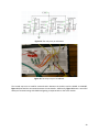
Enclosure Assembly
The enclosure was chosen because the container contained a retained o-ring for waterproof capability.
This is important because, should there be a water or coolant leak in the heat pump at the site, the test
device would not be affected. The box had molded standoffs in it for mounting devices, but were too
close to the wall to be effective. A Dremel rotary tool was used to cut out the pre-existing standoffs and
white standoffs were super-glued into position for mounting the Arduino and Max485. Standard
computer screws (4-32s) were used to fasten the boards into place.
For mounting the Max485, two female headers (4 pin) were soldered through a hole of Plexi-glass to 22
AWG wires. The wires were to be connected to the Arduino board to enable RS485 communication. The
other side has wires that enable the RS485 communication to interface with the DXM2 communication
pins.
The standoffs for the Arduino were set in corresponding locations with the pre-set holes on the Arduino.
Not all holes were capable of having screws installed due to the proximity of the female headers used to
attach wires for the pins.
Four standoffs and three screws secure the Arduino in place. The relay shield sits on top of the Arduino
matching to the pass through pins on the shield. Power is passed from the Arduino to the relay shield in
this way. Jumpers are connected to allow digital communications to the relays and Bluetooth adapter.
Three through holes were drilled into one side of the enclosure. This allowed RS485 and 24VAC wires to
be accessed outside the enclosure. The third hole was for an off and on toggle (STSP) switch to be
installed. Inside the enclosure, a 9 volt battery connector was soldered to one pin of the switch then to a
common male power connector that fits to the female power connector to the Arduino. The other pin
was from the ground side of the male power connector to the other pin on the switch.
The 9 volt battery is capable of sliding under the wires routed from the Arduino to the outside of the
enclosure ensuring physical security and easy access for when the battery needs replaced.
Everything is contained inside the enclosure. The enclosure has enough room for heat dissipation
without the need for active cooling through a fan. Once the wires are set to the desired length, the two
holes containing the 24VAC and RS485 wires can be filled in with a flexible bond and allowed to air cure.
The cure time is dependent on the type of bond used to fill the holes.
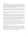
Component Integration
Figure 9 shows the system schematic diagram. The layout of the hardware consists of interfacing the
Arduino with the DXM2 via the SSR relays. There are three relays that are associated with three
components. The Fan (pin G) connected to the control signal pin 13 on the Arduino. The compressor in
stage one (pin Y1) connected to the control signal pin 12 on the Arduino. The reversing valve (pin O)
connected to the control signal pin 11 on the Arduino. The BluetoothV3 is intended for monitoring the
test mode wirelessly by acquiring different data collected by the DXM2 board.
23
Figure 9: Hardware schematic diagram and fully integrated.
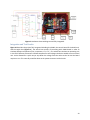
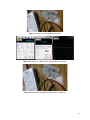
Integration and Test Results
Figure 10 describes the project fully integrated including the DXM2, the control board of the HVAC unit,
and the switch box (Figure 11). The switch box consists of interacting with DXM2 board in order to
simulate different components (Fan, compressor, LT1, LT2…). The switch box simulates an operating unit
in the field. Different resistances simulate temperatures and voltages the device would see on an actual
unit. It also allowed for a quick way to step down the voltage from the outlet to the 24 VAC the board
requires to run. This normally would be down at the power contactor inside the unit.
24
Figure 10: Hardware fully integrated.
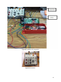
Figure 11: Switch box.
25
Figure 12: Example of G, Y1, O, R and Power IN (R) connections on the DXM2 Board.
Test Plan
The test plan was to interface the relay with DXM2 board for different components with the Arduino
and the shield. The shield has the three relays plus the Bluetooth module.
Figure 13: Relays schematic left: fully integrated on the shield right.
Once this set up was verified to be working correctly using the switch box, interfacing was done
between the Bluetooth and the microcontroller. This step consists of engaging in the test mode which is
cycling on/off the Fan 3 times in succession. Then once the unit is in test mode you can run the Fan,
Compressor in stage 1, and the reversing valve, using the Arduino via Bluetooth. This step was successful
and Figure 17 shows the functionality of the relays using MyDAQ oscilloscope.
With the communication between Arduino and Android complete, the idea of turning on LEDs allowed
the ability for the Arduino to activate a photo diode and turn on a MOSFET via photo-voltaic diode on its
base.
The first part was to connect the relay and understand the built in package. From the schematic of the
relay, it shows a resistor on the photo diode but does not show if it is inside. The resistor was assumed
to be inside the package. The first relay burned. The next relay used had a 1kΩ at the base of the photo
diode. Figures 14, 15, 16, and 17 below show using a MyDAQ for additional data acquisition of
waveforms with voltages at MOSFET cutoff, activation, and saturation.
26
Figure 14: A relay set up using MyDAQ at cutoff.
Figure 15: Frequency on MOSFET with photo diode bias at cutoff.
Figure 16: Photo diode at MOSFET biased. AC now conducting.
27
Figure 17: Photo diode at 1.90V to bias the MOSFET and allows AC signal to pass.
Figure 18: The VDC at 5V to replicate a high from the Arduino.
The relay can now be controlled fully by a digital port from the Arduino allowing the 24VAC from the
control board to turn on the fan, compressor and reversing valve. The schematic for adaption looks like
Figures 19 and 20 below.
28
Figure 19: The relay array on schematic.
Figure 20: The relay array on breadboard.
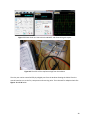
The second step was to establish communication between the Arduino and the DXM2 via MAX485.
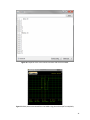
Figure 21 illustrated the connection between the two boards. Additionally, Figure 22 shows a successful
attempt of communicating with DXM2 and getting a response back on the serial monitor.
29
Figure 21: Communication between Arduino and DXM2 via Max485.
30
Figure 22: response of the serial number and fault code from the DXM2.
Figure 23: data packet transmitted from the DXM2 using the oscilloscope from MyDAQ.
31
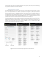
The following image (Figure 24) is a screenshot of part of the application. After the buttons LT1 and LT2
for both Cooling and Heating Mode have been pressed. It is noticeable that the words ‘Data’ from Figure
7 have been replaced with temperatures obtained from the DXM2 board.
Figure 24: screenshot of application after data has been collected.
Data format for all received packets is 1 start bit, 8 data bits, 2 stop bits. Data is transmitted least
significant bit first. Data rate is 9.6 Kpbs. The control shall keep its RS485 bus driver disabled (high
impedance) when not transmitting, and turn off its driver within 1.2mS of completing transmit of a
packet.
The "A+" terminal is non-inverted data and the control provides a weak (12uA nominal) pull-down to
ground when the driver is not enabled. The "B–" terminal is inverted data and the control provides a
weak (12uA nominal) pull-up to +5VDC. The weak pull-up/pull-down guarantees the bus is idle when no
devices are driving the bus.
2
3
4
5
6
7
START
1
1 STOP BIT
0
1 PARITY BIT
B
1 START BIT
A
Figure 25: data packet format.
All data is transmitted in packets to allow orderly control over which device is driving the bus. The
communication consists of a “Master” device sending command packets, and “slave” devices
responding to the packets intended for the slave. Each slave has a unique address, therefore only one
device at a time should be transmitting. The packet shall be considered complete if more than 2870uS
elapses without receiving a complete byte. Packets may be various lengths as needed for each function
code and reply. Packets intended for this control, and sent by this control will not exceed 36 bytes in
length (including CRC value).
32
The slave shall begin reply to queries directed to it 2.5mS after the end of the query packet. If bus
activity is detected within this 2.5mS period, the slave cancels the pending reply. The master shall
timeout if a response has not begun within 7 ms. The communications bus will be considered idle if no
transmissions have occurred for 2.5 seconds. More information about data transmission can be found in
Appendix A.
Field Testing
On Tuesday April 8th the group scheduled a field test of the device at the home of a customer who has a
ClimateMaster Geothermal Heat Pump installed in her house (Donna). This contact was made through
ClimateMaster and the installing contractor Pat from Geothermal Sales and Services.
As the attached video shows, the test was performed flawlessly. First we attached our device in place of
the communicating thermostat (the RS485 terminal). Then we connected to the Load Pins (Y1, G, O, R)
and to the Power In R and Ground C. After these connections were made we put the unit in test mode
(allow us full control over the unit) and subsequently ran the unit in both heating and cooling mode for
10 mins each. While in these modes we were able to measure the temperatures, voltages, and other
pertinent information the DXM2 board supplies using the App that was developed and saved the
corresponding startup sheet to the Tablet. The whole testing process took approximately 1 hr.
33
Section IV: Cost Analysis/Estimation
34
Bill of Materials
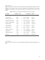
Table 1 describes the cost analysis for the whole design. This table shows different components that are
included into the design in order to meet the requirements and specifications for the project.
Additionally, the table defines the quantities needed for each component and the name for each
supplier.
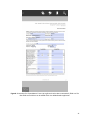
Table 1: Table with information about the different elements of the project
Part Name
Arduino Mega ADK
Price/Unit
Units
Part Number
$69.95
1
$0.39
4
$1.56 SR60-ND
Digi-Key
$21.90
1
$21.90 TEL0026
DFRobot
Arduino Prototype Shield
$9.95
1
$9.95 DEV-07914
SparkFun
Enclosure - Flanged (Red)
$7.95
1
$7.95 PRT-11366
SparkFun
Max485 module
$4.50
1
$4.50 EA-100901
YourDruino
Solid State Relays
$2.57
3
$7.71 Z2100-ND
Digi-Key
Beginner Part Kit
$24.95
1
$24.95 KIT-10003
SparkFun
Header, Female 2-pin
$0.29
9
$2.61 S7000-ND
Digi-Key
Toggle Switch
$3.31
1
$3.31 360-3289-ND
Digi-Key
9V Battery Connector
$2.99
1
$2.99 270-324
Radio Shack
9V Battery
$2.39
1
$2.39 A522BP
Radio Shack
Standoff w/ Hole
DFRobot Bluetooth V3
Total cost
$69.95 782-A000069
Vendor
Mouser Electronics
$159.77
Cost Analysis
The total cost is $159.77 which is less than the $400 budget allocated by the Engineering Department of
IPFW.
35
Conclusions
The designed system was successfully tested and evaluated on the job site. After initially evaluating the
conceptual designs for each area presented previously, it was determined that the service technician
would use the Arduino ADK with Bluetooth, Android Smart Phone Device using external memory to back
up the files.
This design meets in its entirety the requirements set by ClimateMaster and IPFW which include running
the units major components (blower fan, compressor, actuator and reversing valve), collecting and
recording the serial number of the DXM2 board that is being tested as well as several temperatures and
voltages from the same DXM2 board. The created device is 100% compatible the provided DXM2 board
and could also be used in other ClimateMaster boards such as the ECM board but for controlling
purposes only since the last mentioned board does not have the RS485 communication ports or the
sensors that the DXM2 board has.
Along with the requirements there were also limitation and constraints that were met. The final design
was able to work within 0-20 ft. from the unit as this is the standard range the technician stands while
operating the unit. In the future the team will be able to know if the sdesign surpasses the test of time
and works after at least 10 years which is expected taking into consideration normal wear and tear. The
device was able to work with the different voltage ranges on each unit and was safe to use by the
technician. The total time spent performing each startup was shorter than the current time a technician
spends in the startup process using the analog method.
Lastly, the final cost was determined to be $159.77 which falls within the $400 budget provided by
IPFW. Based on the evaluation of the design requirements, limitations, and constraints; it was
determined that this design successfully accommodates the desired solution.
36
References
•
Arduino Mega ADK – Last accessed on 5/1/14
http://arduino.cc/en/Main/ArduinoBoardADK
•
MAX-485 datasheet – Last accessed on 5/1/14
http://yourduino.com/sunshop2/index.php?l=product_detail&p=323
•
S112S01 – Last accessed on 5/1/14
https://www.sparkfun.com/products/10636
•
2N3904 transistor data Sheet – Last accessed on 5/1/14
http://www.findchips.com/ref/2N3904
•
Sample C++ Code – Last accessed on 5/1/14
http://stackoverflow.com/questions/15735264/android-to-arduino-uno-wi-fi-shield-stringcommunication
•
Data transfer between Android and Arduino via Bluetooth – Last accessed on 5/1/14
http://english.cxem.net/arduino/arduino5.php
•
Arduino Language Reference – Last accessed on 5/1/14
http://arduino.cc/en/Reference/HomePage
37
Appendices
Appendix A: DMX2 Control Diagnostics RS 485
1. Introduction
The ClimateMaster DXM2 communicating control uses a Modbus based RS–485 protocol.
2. Physical Communications Interface
All compatible ClimateMaster communicating devices will have appropriate hardware to be
connected to a ClimateMaster Modbus based RS485 network.
2.1. Physical Connections
2.1.1. A+ Connection
The A+ connection will be the positive connection for the RS485 serial communications
network.
2.1.2. B- Connection
The B– connection will be the negative connection for the RS485 serial communications
network.
2.2. Data Structure
Data format is 1 start bit, 8 data bits, 2 stop bits. Data is transmitted least significant bit first.
Data rate is 9.6 Kpbs. The control shall keep its RS485 bus driver disabled (high impedance)
when not transmitting, and turn off its driver within 1.2mS of completing transmit of a packet.
The "A+" terminal is non-inverted data and the control provides a weak (12uA nominal) pulldown to ground when the driver is not enabled. The "B–" terminal is inverted data and the
control provides a weak (12uA nominal) pull-up to +5VDC. The weak pull-up/pull-down
guarantees the bus is idle when no devices are driving the bus.
2
3
4
5
6
7
START
1
1 STOP BIT
0
1 PARITY BIT
B
1 START BIT
A
All data is transmitted in packets to allow orderly control over which device is driving the bus.
The communication consists of a “Master” device sending command packets, and “slave”
devices responding to the packets intended for the slave. Each slave has a unique address,
therefore only one device at a time should be transmitting. The packet shall be considered
complete if more than 2870uS elapses without receiving a complete byte. Packets may be
various lengths as needed for each function code and reply. Packets intended for this control,
and sent by this control will not exceed 36 bytes in length (including CRC value).
The slave shall begin reply to queries directed to it 2.5mS after the end of the query packet. If
bus activity is detected within this 2.5mS period, the slave cancels the pending reply. The
38
master shall timeout if a response has not begun within 7 ms. The communications bus will be
considered idle if no transmissions have occurred for 2.5 seconds.
3. DXM2 Diagnostic Data Packets
The following sections show the required data packets (all values in hexadecimal) to be sent to the
DXM2 with dipswitch SW3-1 in the off position, to retrieve the specified data points.
3.1. Serial Number
To read the last four digits of the unit serial number stored in a DXM2 during manufacturing,
the following data packet should be sent to the DXM2:
30 03 51 1F 00 01 A1 11
The response packet should be similar to the following, with the highlighted hexadecimal
values containing the currently stored 16 bit value:
30 03 02 12 34 C5 80
In this case the response value of 1234 hex is interpreted as 4660
3.2. Fault Codes
To read the current and last five stored fault codes stored in a DXM2, the following data packet
should be sent to the DXM2:
30 03 51 1C 00 03 D0 D0
The response packet should be similar to the following, with the highlighted hexadecimal
values containing the current and stored fault code values:
30 03 06 01 02 03 04 05 06 4B F3
In this case the response value of 01 would be the current fault code, 02 would be the first
stored fault code value, 03 would be the second stored fault code value, 04 would be the third
stored fault code value, 05 would be the fourth stored fault code value, and 06 would be the
fifth stored fault code value.
3.3. LT1 Temperature
To read the LT1 temperature from a DXM2 the following data packet should be sent to the
DXM2:
30 03 51 20 00 01 91 1D
The response packet should be similar to the following, with the highlighted hexadecimal
values containing the current LT1 temperature value:
30 03 02 03 06 45 72
Temperature values are in 1/10 degrees F, so the hexadecimal value above of 0x0306 would be
translated to a decimal value of 774, equivalent to a temperature of 77.4 degrees.
39
3.4. LT2 Temperature
To read the LT2 temperature from a DXM2 the following data packet should be sent to the
DXM2:
30 03 51 21 00 01 C0 DD
The response packet should be similar to the following, with the highlighted hexadecimal
values containing the current LT2 temperature value:
30 03 02 03 06 45 72
Temperature values are in 1/10 degrees F, so the hexadecimal value above of 0x0306 would be
translated to a decimal value of 774, equivalent to a temperature of 77.4 degrees.
3.5. Entering Water Temperature
To read the entering water temperature from a DXM2 the following data packet should be sent
to the DXM2:
30 03 51 23 00 01 61 1D
The response packet should be similar to the following, with the highlighted hexadecimal
values containing the current entering water temperature value:
30 03 02 02 06 45 72
Temperature values are in 1/10 degrees F, so the hexadecimal value above of 0x0206 would be
translated to a decimal value of 518, equivalent to a temperature of 51.8 degrees.
3.6. Leaving Water Temperature
To read the leaving water temperature from a DXM2 the following data packet should be sent
to the DXM2:
30 03 51 24 00 01 D0 DC
The response packet should be similar to the following, with the highlighted hexadecimal
values containing the current leaving water temperature value:
30 03 02 01 E1 45 72
Temperature values are in 1/10 degrees F, so the hexadecimal value above of 0x01E1 would be
translated to a decimal value of 481, equivalent to a temperature of 48.1 degrees.
3.7. Leaving Air Temperature
To read the leaving air temperature from a DXM2 the following data packet should be sent to
the DXM2:
30 03 51 25 00 01 81 1C
The response packet should be similar to the following, with the highlighted hexadecimal
values containing the current leaving air temperature value:
30 03 02 03 16 45 72
40
Temperature values are in 1/10 degrees F, so the hexadecimal value above of 0x0316 would be
translated to a decimal value of 790, equivalent to a temperature of 79.0 degrees.
3.8. Compressor Discharge Temperature
To read the compressor discharge temperature from a DXM2 the following data packet should
be sent to the DXM2:
30 03 51 27 00 01 20 DC
The response packet should be similar to the following, with the highlighted hexadecimal
values containing the current compressor discharge temperature value:
30 03 02 05 2A 45 72
Temperature values are in 1/10 degrees F, so the hexadecimal value above of 0x052A would be
translated to a decimal value of 1322, equivalent to a temperature of 132.2 degrees.
3.9. Entering Hot Water Temperature
To read the entering hot water temperature from a DXM2 the following data packet should be
sent to the DXM2:
30 03 51 26 00 01 71 1C
The response packet should be similar to the following, with the highlighted hexadecimal
values containing the current entering hot water temperature value:
30 03 02 04 83 45 72
Temperature values are in 1/10 degrees F, so the hexadecimal value above of 0x0483 would be
translated to a decimal value of 1155, equivalent to a temperature of 115.5 degrees.
3.10. Target Airflow
To read the target airflow from a DXM2 the following data packet should be sent to the DXM2:
30 03 51 14 00 01 D0 D3
The response packet should be similar to the following, with the highlighted hexadecimal
values containing the current target airflow value:
30 03 02 02 26 45 72
Airflow values are in CFM, so the hexadecimal value above of 0x0226 would be translated to a
decimal value of 550, equivalent to a target airflow of 550 CFM.
3.11. Blower Speed
To read the blower speed from a DXM2 the following data packet should be sent to the DXM2:
30 03 51 28 00 01 10 DF
The response packet should be similar to the following, with the highlighted hexadecimal
values containing the current blower speed value:
30 03 02 01 6F 45 72
41
Blower speed values are in RPM, so the hexadecimal value above of 0x016F would be
translated to a decimal value of 367, equivalent to a blower speed of 367 RPM.
3.12. Pump Speed
To read the target pump speed from a DXM2 the following data packet should be sent to the
DXM2:
30 03 51 15 00 01 81 13
The response packet should be similar to the following, with the highlighted hexadecimal value
containing the current target pump speed value:
30 03 02 00 28 45 72
Pump speed values are in percent, so the hexadecimal value above of 0x28 would be translated
to a decimal value of 40, equivalent to a target pump speed of 40%.
3.13. Control Voltage
To read the control voltage from a DXM2 the following data packet should be sent to the
DXM2:
30 03 51 2A 00 01 B1 1F
The response packet should be similar to the following, with the highlighted hexadecimal
values containing the current control voltage value:
30 03 02 00 EC C4 0D
Temperature values are in 1/10 volts VAC, so the hexadecimal value above of 0x00EC would be
translated to a decimal value of 236, equivalent to a voltage of 23.6
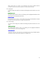
42
Appendix B: DMX2 Data Connector RS485 (schematic)
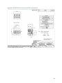
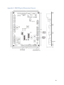
43
Appendix C: DXM2 Physical Dimension & Layout
44
Appendix D: Program List
Android Code
HVACDMAD.Java-Main Activity
package com.example.hvacdmad;
import android.net.Uri;
import android.os.Bundle;
import android.app.Activity;
import android.view.Menu;
import java.io.File;
import java.io.FileOutputStream;
import java.io.IOException;
import java.io.InputStream;
import java.io.OutputStream;
import java.lang.reflect.Method;
import java.text.DateFormat;
import java.text.SimpleDateFormat;
import java.util.Date;
import java.util.UUID;
//import com.itextpdf.text.pdf.AcroFields;
//import com.itextpdf.text.pdf.PdfReader;
//import com.itextpdf.text.pdf.PdfStamper;
import com.example.hvacdmad.R;
import com.itextpdf.text.pdf.AcroFields;
import com.itextpdf.text.pdf.PdfReader;
import com.itextpdf.text.pdf.PdfStamper;
import android.app.Activity;
import android.bluetooth.BluetoothAdapter;
import android.bluetooth.BluetoothDevice;
import android.bluetooth.BluetoothSocket;
import android.content.ActivityNotFoundException;
import android.content.Intent;
import android.os.Build;
import android.os.Bundle;
import android.os.Environment;
import android.os.Handler;
import android.util.Log;
import android.view.View;
45
import android.view.View.OnClickListener;
import android.widget.Button;
import android.widget.CompoundButton;
import android.widget.CompoundButton.OnCheckedChangeListener;
import android.widget.TextView;
import android.widget.RadioButton;
import android.widget.ToggleButton;
import android.widget.EditText;
import android.widget.Switch;
import android.widget.Toast;
public class MainActivity extends Activity {
private static final String TAG = "bluetooth1";
private static String OUT_FILE = Environment.getExternalStorageDirectory()
+ "/";
String Outputfile= "";
Button Serial, Fault, LT1, LT2, ENTWATER, LEAVWATER, LEAVAIR, COMPDIST, ENTHOTW, TARGETA;
Button BLOWERS, PUMPS, CONTROLVOLT, GenPDF, ViewPDF;
Button lt1, lt2, entwater, leavwater, leavair, compdist, enthotw, targeta, blowers;
Button pumps, controlvolt;
ToggleButton toggleButton1, toggleButton2;
Switch switch1;
TextView DataSerial, DataFault, DataLT1, DataLT2, DataENTWATER, DataLEAVWATER;
TextView DataLEAVAIR, DataCOMPDIST, DataENTHOTW, DataTARGETA, DataBLOWERS, DataPUMPS;
TextView DataCONTROLVOLT, Datalt1, Datalt2, Dataentwater, Dataleavwater, Dataleavair;
TextView Datacompdist, Dataenthotw, Datatargeta, Datablowers, Datapumps, Datacontrolvolt;
EditText ReturnAirCM, ReturnAirHM, WaterFlowCM, WaterFlowHM;
EditText CompAmpsCM, CompAmpsHM, CompVoltsCM, CompVoltsHM, MotorAmpsCM,
MotorAmpsHM;
EditText WaterTDiffCM, WaterTDiffHM, AirTDiffCM, AirTDiffHM;
EditText Address, Job, Model, UnitLocation, OrderNumber, Antifreeze, Type;
RadioButton FahrenheitRadio, PSIGradio;
Handler h;
final int RECIEVE_MESSAGE = 1;
// Status for Handler
private BluetoothAdapter btAdapter = null;
private BluetoothSocket btSocket = null;
private OutputStream outStream = null;
private StringBuilder sb = new StringBuilder();
private ConnectedThread mConnectedThread;
46
// SPP UUID service
private static final UUID MY_UUID = UUID.fromString("00001101-0000-1000-8000-00805F9B34FB");
// MAC-address of Bluetooth module (you must edit this line)
private static String address = "20:13:08:28:05:96";
String sent;
/** Called when the activity is first created. */
@Override
public void onCreate(Bundle savedInstanceState) {
super.onCreate(savedInstanceState);
setContentView(R.layout.activity_main2);
Serial = (Button) findViewById(R.id.Serial);
Fault = (Button) findViewById(R.id.Fault);
LT1 = (Button) findViewById(R.id.LT1);
LT2 = (Button) findViewById(R.id.LT2);
ENTWATER = (Button) findViewById(R.id.ENTWATER);
LEAVWATER = (Button) findViewById(R.id.LEAVWATER);
LEAVAIR = (Button) findViewById(R.id.LEAVAIR);
COMPDIST = (Button) findViewById(R.id.COMPDIST);
ENTHOTW = (Button) findViewById(R.id.ENTHOTW);
TARGETA = (Button) findViewById(R.id.TARGETA);
BLOWERS = (Button) findViewById(R.id.BLOWERS);
PUMPS = (Button) findViewById(R.id.PUMPS);
CONTROLVOLT = (Button) findViewById(R.id.CONTROLVOLT);
lt1 = (Button) findViewById(R.id.lt1);
lt2 = (Button) findViewById(R.id.lt2);
entwater = (Button) findViewById(R.id.entwater);
leavwater = (Button) findViewById(R.id.leavwater);
leavair = (Button) findViewById(R.id.leavair);
compdist = (Button) findViewById(R.id.compdist);
enthotw = (Button) findViewById(R.id.enthotw);
targeta = (Button) findViewById(R.id.targeta);
blowers = (Button) findViewById(R.id.blowers);
pumps = (Button) findViewById(R.id.pumps);
controlvolt = (Button) findViewById(R.id.controlvolt);
toggleButton1 = (ToggleButton) findViewById(R.id.toggleButton1);
toggleButton2 = (ToggleButton) findViewById(R.id.toggleButton2);
switch1 = (Switch) findViewById(R.id.switch1);
DataSerial = (TextView) findViewById(R.id.DataSerial);
47
DataFault = (TextView) findViewById(R.id.DataFault);
DataLT1 = (TextView) findViewById(R.id.DataLT1);
DataLT2 = (TextView) findViewById(R.id.DataLT2);
DataENTWATER = (TextView) findViewById(R.id.DataENTWATER);
DataLEAVWATER = (TextView) findViewById(R.id.DataLEAVWATER);
DataLEAVAIR = (TextView) findViewById(R.id.DataLEAVAIR);
DataCOMPDIST = (TextView) findViewById(R.id.DataCOMPDIST);
DataENTHOTW = (TextView) findViewById(R.id.DataENTHOTW);
DataTARGETA = (TextView) findViewById(R.id.DataTARGETA);
DataBLOWERS = (TextView) findViewById(R.id.DataBLOWERS);
DataPUMPS = (TextView) findViewById(R.id.DataPUMPS);
DataCONTROLVOLT = (TextView) findViewById(R.id.DataCONTROLVOLT);
Datalt1 = (TextView) findViewById(R.id.Datalt1);
Datalt2 = (TextView) findViewById(R.id.Datalt2);
Dataentwater = (TextView) findViewById(R.id.Dataentwater);
Dataleavwater = (TextView) findViewById(R.id.Dataleavwater);
Dataleavair = (TextView) findViewById(R.id.Dataleavair);
Datacompdist = (TextView) findViewById(R.id.Datacompdist);
Dataenthotw = (TextView) findViewById(R.id.Dataenthotw);
Datatargeta = (TextView) findViewById(R.id.Datatargeta);
Datablowers = (TextView) findViewById(R.id.Datablowers);
Datapumps = (TextView) findViewById(R.id.Datapumps);
Datacontrolvolt = (TextView) findViewById(R.id.Datacontrolvolt);
FahrenheitRadio = (RadioButton) findViewById(R.id.radio0);
PSIGradio = (RadioButton) findViewById(R.id.radio2);
Address = (EditText) findViewById(R.id.Address);
Job = (EditText) findViewById(R.id.Job);
Model = (EditText) findViewById(R.id.Model);
UnitLocation = (EditText) findViewById(R.id.UnitLocation);
OrderNumber = (EditText) findViewById(R.id.OrderNumber);
Antifreeze = (EditText) findViewById(R.id.Antifreeze);
Type = (EditText) findViewById(R.id.Type);
ReturnAirCM = (EditText) findViewById(R.id.ReturnAirCM);
ReturnAirHM = (EditText) findViewById(R.id.ReturnAirHM);
WaterFlowCM = (EditText) findViewById(R.id.WaterFlowCM);
WaterFlowHM = (EditText) findViewById(R.id.WaterFlowHM);
CompAmpsCM = (EditText) findViewById(R.id.CompAmpsCM);
CompAmpsHM = (EditText) findViewById(R.id.CompAmpsHM);
CompVoltsCM = (EditText) findViewById(R.id.CompVoltsCM);
CompVoltsHM = (EditText) findViewById(R.id.CompVoltsHM);
MotorAmpsCM = (EditText) findViewById(R.id.MotorAmpsCM);
MotorAmpsHM = (EditText) findViewById(R.id.MotorAmpsHM);
WaterTDiffCM = (EditText) findViewById(R.id.WaterTDiffCM);
48
WaterTDiffHM = (EditText) findViewById(R.id.WaterTDiffHM);
AirTDiffCM = (EditText) findViewById(R.id.AirTDiffCM);
AirTDiffHM = (EditText) findViewById(R.id.AirTDiffHM);
h = new Handler() {
public void handleMessage(android.os.Message msg) {
switch (msg.what) {
case RECIEVE_MESSAGE:
// if receive massage
byte[] readBuf = (byte[]) msg.obj;
String strIncom = new String(readBuf, 0, msg.arg1);
// create string from bytes array
sb.append(strIncom);
// append string
int endOfLineIndex = sb.indexOf("\r\n");
// determine the end-of-line
//String s = sent.charAt(0) + " " + sb.toString();
//Log.d("test2", s);
switch (sent.charAt(0)){
case 'S':
if (endOfLineIndex > 0) {
// if end-of-line,
String sbprint = sb.substring(0, endOfLineIndex);
// extract string
sb.delete(0, sb.length());
// and clear
DataSerial.setText(sbprint);
// update TextView
Serial.setEnabled(true);
}
break;
case 'F':
if (endOfLineIndex > 0) {
// if end-of-line,
String sbprint = sb.substring(0, endOfLineIndex);
// extract string
sb.delete(0, sb.length());
// and clear
DataFault.setText(sbprint);
// update TextView
Fault.setEnabled(true);
}
break;
case 'L':
if (endOfLineIndex > 0) {
// if end-of-line,
String sbprint = sb.substring(0, endOfLineIndex);
// extract string
sb.delete(0, sb.length());
// and clear
49
DataLT1.setText(sbprint);
LT1.setEnabled(true);
// update TextView
}
break;
case '1':
if (endOfLineIndex > 0) {
// if end-of-line,
String sbprint = sb.substring(0, endOfLineIndex);
// extract string
sb.delete(0, sb.length());
// and clear
Datalt1.setText(sbprint);
// update TextView
lt1.setEnabled(true);
}
break;
case 'l':
if (endOfLineIndex > 0) {
// if end-of-line,
String sbprint = sb.substring(0, endOfLineIndex);
// extract string
sb.delete(0, sb.length());
// and clear
DataLT2.setText(sbprint);
// update TextView
LT2.setEnabled(true);
}
break;
case '2':
if (endOfLineIndex > 0) {
// if end-of-line,
String sbprint = sb.substring(0, endOfLineIndex);
// extract string
sb.delete(0, sb.length());
// and clear
Datalt2.setText(sbprint);
// update TextView
lt2.setEnabled(true);
}
break;
case 'W':
if (endOfLineIndex > 0) {
// if end-of-line,
String sbprint = sb.substring(0, endOfLineIndex);
// extract string
sb.delete(0, sb.length());
// and clear
DataENTWATER.setText(sbprint);
// update TextView
ENTWATER.setEnabled(true);
}
break;
case 'w':
if (endOfLineIndex > 0) {
// if end-of-line,
String sbprint = sb.substring(0, endOfLineIndex);
// extract string
50
sb.delete(0, sb.length());
Dataentwater.setText(sbprint);
entwater.setEnabled(true);
// and clear
// update TextView
}
break;
case 'R':
if (endOfLineIndex > 0) {
// if end-of-line,
String sbprint = sb.substring(0, endOfLineIndex);
// extract string
sb.delete(0, sb.length());
// and clear
DataLEAVWATER.setText(sbprint);
// update TextView
LEAVWATER.setEnabled(true);
}
break;
case 'r':
if (endOfLineIndex > 0) {
// if end-of-line,
String sbprint = sb.substring(0, endOfLineIndex);
// extract string
sb.delete(0, sb.length());
// and clear
Dataleavwater.setText(sbprint);
// update TextView
leavwater.setEnabled(true);
}
break;
case 'A':
if (endOfLineIndex > 0) {
// if end-of-line,
String sbprint = sb.substring(0, endOfLineIndex);
// extract string
sb.delete(0, sb.length());
// and clear
DataLEAVAIR.setText(sbprint);
// update TextView
LEAVAIR.setEnabled(true);
}
break;
case 'a':
if (endOfLineIndex > 0) {
// if end-of-line,
String sbprint = sb.substring(0, endOfLineIndex);
// extract string
sb.delete(0, sb.length());
// and clear
Dataleavair.setText(sbprint);
// update TextView
leavair.setEnabled(true);
}
break;
case 'D':
if (endOfLineIndex > 0) {
// if end-of-line,
51
String sbprint = sb.substring(0, endOfLineIndex);
// extract string
sb.delete(0, sb.length());
// and clear
DataCOMPDIST.setText(sbprint);
// update TextView
COMPDIST.setEnabled(true);
}
break;
case 'd':
if (endOfLineIndex > 0) {
// if end-of-line,
String sbprint = sb.substring(0, endOfLineIndex);
// extract string
sb.delete(0, sb.length());
// and clear
Datacompdist.setText(sbprint);
// update TextView
compdist.setEnabled(true);
}
break;
case 'E':
if (endOfLineIndex > 0) {
// if end-of-line,
String sbprint = sb.substring(0, endOfLineIndex);
// extract string
sb.delete(0, sb.length());
// and clear
DataENTHOTW.setText(sbprint);
// update TextView
ENTHOTW.setEnabled(true);
}
break;
case 'e':
if (endOfLineIndex > 0) {
// if end-of-line,
String sbprint = sb.substring(0, endOfLineIndex);
// extract string
sb.delete(0, sb.length());
// and clear
Dataenthotw.setText(sbprint);
// update TextView
enthotw.setEnabled(true);
}
break;
case 'G':
if (endOfLineIndex > 0) {
// if end-of-line,
String sbprint = sb.substring(0, endOfLineIndex);
// extract string
sb.delete(0, sb.length());
// and clear
DataTARGETA.setText(sbprint);
// update TextView
TARGETA.setEnabled(true);
}
break;
case 'g':
52
if (endOfLineIndex > 0) {
// if end-of-line,
String sbprint = sb.substring(0, endOfLineIndex);
// extract string
sb.delete(0, sb.length());
// and clear
Datatargeta.setText(sbprint);
// update TextView
targeta.setEnabled(true);
}
break;
case 'B':
if (endOfLineIndex > 0) {
// if end-of-line,
String sbprint = sb.substring(0, endOfLineIndex);
// extract string
sb.delete(0, sb.length());
// and clear
DataBLOWERS.setText(sbprint);
// update TextView
BLOWERS.setEnabled(true);
}
break;
case 'b':
if (endOfLineIndex > 0) {
// if end-of-line,
String sbprint = sb.substring(0, endOfLineIndex);
// extract string
sb.delete(0, sb.length());
// and clear
Datablowers.setText(sbprint);
// update TextView
blowers.setEnabled(true);
}
break;
case 'P':
if (endOfLineIndex > 0) {
// if end-of-line,
String sbprint = sb.substring(0, endOfLineIndex);
// extract string
sb.delete(0, sb.length());
// and clear
DataPUMPS.setText(sbprint);
// update TextView
PUMPS.setEnabled(true);
}
break;
case 'p':
if (endOfLineIndex > 0) {
// if end-of-line,
String sbprint = sb.substring(0, endOfLineIndex);
// extract string
sb.delete(0, sb.length());
// and clear
Datapumps.setText(sbprint);
// update TextView
pumps.setEnabled(true);
}
break;
case 'V':
53
if (endOfLineIndex > 0) {
// if end-of-line,
String sbprint = sb.substring(0, endOfLineIndex);
// extract string
sb.delete(0, sb.length());
// and clear
DataCONTROLVOLT.setText(sbprint);
// update TextView
CONTROLVOLT.setEnabled(true);
}
break;
case 'v':
if (endOfLineIndex > 0) {
// if end-of-line,
String sbprint = sb.substring(0, endOfLineIndex);
// extract string
sb.delete(0, sb.length());
// and clear
Datacontrolvolt.setText(sbprint);
// update TextView
controlvolt.setEnabled(true);
}
break;
}
//Log.d(TAG, "...String:"+ sb.toString() + "Byte:" + msg.arg1 + "...");
break;
}
};
};
btAdapter = BluetoothAdapter.getDefaultAdapter();
checkBTState();
switch1.setOnCheckedChangeListener(new CompoundButton.OnCheckedChangeListener() {
public void onCheckedChanged(CompoundButton buttonView, boolean isChecked) {
if (isChecked){ // Do Something
sendData("T");
} else {
if (buttonView != toggleButton1) {
toggleButton1.setChecked(false);
sendData("c");
}
if (buttonView != toggleButton2) {
toggleButton2.setChecked(false);
sendData("h");
}
sendData("t");
54
}
}
});
toggleButton1.setOnCheckedChangeListener(new CompoundButton.OnCheckedChangeListener() {
public void onCheckedChanged(CompoundButton buttonView, boolean isChecked) {
if (isChecked && buttonView != toggleButton2) {
sendData("C"); // The toggle is enabled
toggleButton2.setChecked(false);
toggleButton2.setEnabled(false);
Toast.makeText(getBaseContext(), "Cooling Mode ON!", Toast.LENGTH_SHORT).show();
}
else {
sendData("c"); // The toggle is disabled
toggleButton2.setEnabled(true);
Toast.makeText(getBaseContext(), "Cooling Mode OFF!", Toast.LENGTH_SHORT).show();
}
}
});
toggleButton2.setOnCheckedChangeListener(new CompoundButton.OnCheckedChangeListener() {
public void onCheckedChanged(CompoundButton buttonView, boolean isChecked) {
if (isChecked && buttonView != toggleButton1) {
sendData("H"); // The toggle is enabled
toggleButton1.setChecked(false);
toggleButton1.setEnabled(false);
Toast.makeText(getBaseContext(), "Heating Mode ON!", Toast.LENGTH_SHORT).show();
}
else {
sendData("h"); // The toggle is disabled
toggleButton1.setEnabled(true);
Toast.makeText(getBaseContext(), "Heating Mode OFF!", Toast.LENGTH_SHORT).show();
}
}
});
Serial.setOnClickListener(new OnClickListener() {
public void onClick(View v) {
sendData("S");
Toast.makeText(getBaseContext(), "Receiving Serial Number", Toast.LENGTH_SHORT).show();
}
});
55
Fault.setOnClickListener(new OnClickListener() {
public void onClick(View v) {
DataFault.setText("");
sendData("F");
Toast.makeText(getBaseContext(), "Receiving Fault Codes", Toast.LENGTH_SHORT).show();
}
});
LT1.setOnClickListener(new OnClickListener() {
public void onClick(View v) {
sendData("L");
Toast.makeText(getBaseContext(), "Receiving LT1 Data", Toast.LENGTH_SHORT).show();
}
});
lt1.setOnClickListener(new OnClickListener() {
public void onClick(View v) {
sendData("1");
Toast.makeText(getBaseContext(), "Receiving LT1 Data", Toast.LENGTH_SHORT).show();
}
});
LT2.setOnClickListener(new OnClickListener() {
public void onClick(View v) {
sendData("l");
Toast.makeText(getBaseContext(), "Receiving LT2 Data", Toast.LENGTH_SHORT).show();
}
});
lt2.setOnClickListener(new OnClickListener() {
public void onClick(View v) {
sendData("2");
Toast.makeText(getBaseContext(), "Receiving LT2 Data", Toast.LENGTH_SHORT).show();
}
});
ENTWATER.setOnClickListener(new OnClickListener() {
public void onClick(View v) {
sendData("W");
Toast.makeText(getBaseContext(), "Receiving Entering Water Temperature",
Toast.LENGTH_SHORT).show();
}
});
56
entwater.setOnClickListener(new OnClickListener() {
public void onClick(View v) {
sendData("w");
Toast.makeText(getBaseContext(), "Receiving Entering Water Temperature",
Toast.LENGTH_SHORT).show();
}
});
LEAVWATER.setOnClickListener(new OnClickListener() {
public void onClick(View v) {
sendData("R");
Toast.makeText(getBaseContext(), "Receiving Leaving Water Temperature",
Toast.LENGTH_SHORT).show();
}
});
leavwater.setOnClickListener(new OnClickListener() {
public void onClick(View v) {
sendData("r");
Toast.makeText(getBaseContext(), "Receiving Leaving Water Temperature",
Toast.LENGTH_SHORT).show();
}
});
LEAVAIR.setOnClickListener(new OnClickListener() {
public void onClick(View v) {
sendData("A");
Toast.makeText(getBaseContext(), "Receiving Leaving Air Temperature",
Toast.LENGTH_SHORT).show();
}
});
leavair.setOnClickListener(new OnClickListener() {
public void onClick(View v) {
sendData("a");
Toast.makeText(getBaseContext(), "Receiving Leaving Air Temperature",
Toast.LENGTH_SHORT).show();
}
});
COMPDIST.setOnClickListener(new OnClickListener() {
public void onClick(View v) {
sendData("D");
57
Toast.makeText(getBaseContext(), "Receiving Compressor Discharge Temperature",
Toast.LENGTH_SHORT).show();
}
});
compdist.setOnClickListener(new OnClickListener() {
public void onClick(View v) {
sendData("d");
Toast.makeText(getBaseContext(), "Receiving Compressor Discharge Temperature",
Toast.LENGTH_SHORT).show();
}
});
ENTHOTW.setOnClickListener(new OnClickListener() {
public void onClick(View v) {
sendData("E");
Toast.makeText(getBaseContext(), "Receiving Entering Hot Water Temperature",
Toast.LENGTH_SHORT).show();
}
});
enthotw.setOnClickListener(new OnClickListener() {
public void onClick(View v) {
sendData("e");
Toast.makeText(getBaseContext(), "Receiving Entering Hot Water Temperature",
Toast.LENGTH_SHORT).show();
}
});
TARGETA.setOnClickListener(new OnClickListener() {
public void onClick(View v) {
sendData("G");
Toast.makeText(getBaseContext(), "Receiving Target Airflow", Toast.LENGTH_SHORT).show();
}
});
targeta.setOnClickListener(new OnClickListener() {
public void onClick(View v) {
sendData("g");
Toast.makeText(getBaseContext(), "Receiving Target Airflow", Toast.LENGTH_SHORT).show();
}
});
BLOWERS.setOnClickListener(new OnClickListener() {
58
public void onClick(View v) {
sendData("B");
Toast.makeText(getBaseContext(), "Receiving Blower Speed", Toast.LENGTH_SHORT).show();
}
});
blowers.setOnClickListener(new OnClickListener() {
public void onClick(View v) {
sendData("b");
Toast.makeText(getBaseContext(), "Receiving Blower Speed", Toast.LENGTH_SHORT).show();
}
});
PUMPS.setOnClickListener(new OnClickListener() {
public void onClick(View v) {
sendData("P");
Toast.makeText(getBaseContext(), "Receiving Pump Speed", Toast.LENGTH_SHORT).show();
}
});
pumps.setOnClickListener(new OnClickListener() {
public void onClick(View v) {
sendData("p");
Toast.makeText(getBaseContext(), "Receiving Pump Speed", Toast.LENGTH_SHORT).show();
}
});
CONTROLVOLT.setOnClickListener(new OnClickListener() {
public void onClick(View v) {
sendData("V");
Toast.makeText(getBaseContext(), "Receiving Control Voltage", Toast.LENGTH_SHORT).show();
}
});
controlvolt.setOnClickListener(new OnClickListener() {
public void onClick(View v) {
sendData("v");
Toast.makeText(getBaseContext(), "Receiving Control Voltage", Toast.LENGTH_SHORT).show();
}
});
GenPDF = (Button) findViewById(R.id.GenPDF);
GenPDF.setOnClickListener(new OnClickListener() {
59
@Override
public void onClick(View arg0) {
/*
* Generate the PDF
*/
try {
// Open the PDF form
PdfReader reader = new
PdfReader(getResources().openRawResource(R.raw.startupsheetclimatemaster));
// Get the current date/time
DateFormat dateFormat = new SimpleDateFormat("MMMM dd, yyyy
HH:mm:ss");
Date date = new Date();
// Create a copy of the PDF form
Outputfile=OUT_FILE + dateFormat.format(date)+".pdf";
PdfStamper stamper = new PdfStamper(reader, new
FileOutputStream(Outputfile));
// Get the fields in the form
AcroFields form = stamper.getAcroFields();
// Fill in the date field
form.setField("Date", dateFormat.format(date));
// Fill in the Job field
form.setField("Job", Job.getText().toString());
// Fill in the Address field
form.setField("Address", Address.getText().toString());
// Fill in the Model field
form.setField("Model", Model.getText().toString());
// Fill in the Location field
form.setField("Location", UnitLocation.getText().toString());
// Fill in the Sales field
form.setField("Sales", OrderNumber.getText().toString());
// Fill in the Serial field
form.setField("Serial", DataSerial.getText().toString());
60
// Fill in the Fan Motor: Speed Tap (PSC) field
form.setField("Tap", DataBLOWERS.getText().toString());
// Fill in the Entering Fluid Temperature field for Cooling Mode
form.setField("EnteringFCM", DataENTWATER.getText().toString());
// Fill in the Entering Fluid Temperature field for Heating Mode
form.setField("EnteringFHM", Dataentwater.getText().toString());
// Fill in the Leaving Fluid Temperature field for Cooling Mode
form.setField("LeavingFCM", DataLEAVWATER.getText().toString());
// Fill in the Leaving Fluid Temperature field for Heating Mode
form.setField("LeavingFHM", Dataleavwater.getText().toString());
// Fill in the Differential Fluid Temperature field for Cooling Mode
form.setField("FluidTempDiffCM", WaterTDiffCM.getText().toString());
// Fill in the Differential Fluid Temperature field for Heating Mode
form.setField("FluidTempDiffHM", WaterTDiffHM.getText().toString());
// Fill in the Leaving Air Temperature field for Cooling Mode
form.setField("SupplyDBCM", DataLEAVAIR.getText().toString());
// Fill in the Leaving Air Temperature field for Cooling Mode
form.setField("SupplyDBHM", Dataleavair.getText().toString());
// Fill in the Return Air Temperature field for Cooling Mode
form.setField("ReturnDBCM", ReturnAirCM.getText().toString());
// Fill in the Return Air Temperature field for Heating Mode
form.setField("ReturnDBHM", ReturnAirHM.getText().toString());
// Fill in the Differential Air Temperature field for Cooling Mode
form.setField("AirTempDiffCM", AirTDiffCM.getText().toString());
// Fill in the Differential Air Temperature field for Heating Mode
form.setField("AirTempDiffHM", AirTDiffHM.getText().toString());
// Fill in the Water Flow GPM field for Cooling Mode
form.setField("WaterFlowCM", WaterFlowCM.getText().toString());
// Fill in the Water Flow GPM field for Heating Mode
form.setField("WaterFlowHM", WaterFlowHM.getText().toString());
61
// Fill in the Compressor Amps field for Cooling Mode
form.setField("CompAmpsCM", CompAmpsCM.getText().toString());
// Fill in the Compressor Amps field for Heating Mode
form.setField("CompAmpsHM", CompAmpsHM.getText().toString());
// Fill in the Compressor Volts field for Cooling Mode
form.setField("CompVoltsCM", CompVoltsCM.getText().toString());
// Fill in the Compressor Volts field for Heating Mode
form.setField("CompVoltsHM", CompVoltsHM.getText().toString());
// Fill in the Compressor Discharge Temperature field for Cooling Mode
form.setField("DLineTempCM", DataCOMPDIST.getText().toString());
// Fill in the Compressor Discharge Temperature field for Heating Mode
form.setField("DLineTempHM", Datacompdist.getText().toString());
// Fill in the Motor Amps field for Cooling Mode
form.setField("MotorAmpsCM", MotorAmpsCM.getText().toString());
// Fill in the Motor Amps field for Heating Mode
form.setField("MotorAmpsHM", MotorAmpsHM.getText().toString());
// Fill in the Motor Voltage field for Cooling Mode
form.setField("MotorVoltsCM",
DataCONTROLVOLT.getText().toString());
// Fill in the Motor Voltage field for Cooling Mode
form.setField("MotorVoltsHM", Datacontrolvolt.getText().toString());
// Fill in the Antifreeze field for Cooling Mode
form.setField("Antifreeze", Antifreeze.getText().toString());
// Fill in the Type field for Cooling Mode
form.setField("Type", Type.getText().toString());
// Check the F or F check box
if(FahrenheitRadio.isChecked()) {
form.setField("F", "Yes");
}
else {
form.setField("C", "Yes");
62
}
// Check the f or c check box
if(PSIGradio.isChecked()) {
form.setField("PSIG", "Yes");
}
else {
form.setField("kPa", "Yes");
}
stamper.close();
reader.close();
Toast.makeText(getApplicationContext(), "PDF Created",
Toast.LENGTH_LONG).show();
ViewPDF.setEnabled(true);
} catch (Exception e) {
e.printStackTrace();
Toast.makeText(getApplicationContext(),
"Error: PDF Not Created", Toast.LENGTH_LONG).show();
}
}
});
ViewPDF = (Button) findViewById(R.id.ViewPDF);
ViewPDF.setOnClickListener(new OnClickListener() {
@Override
public void onClick(View arg0) {
/*
* View the PDF
*/
File file = new File(Outputfile);
if (file.exists()) {
Uri path = Uri.fromFile(file);
Intent intent = new Intent(Intent.ACTION_VIEW);
intent.setDataAndType(path, "application/pdf");
intent.setFlags(Intent.FLAG_ACTIVITY_CLEAR_TOP);
try {
startActivity(intent);
}
catch (ActivityNotFoundException e) {
63
Toast.makeText(getApplicationContext(),
"No Application Available to View PDF",
Toast.LENGTH_SHORT).show();
}
}
}
});
ViewPDF.setEnabled(false);
}
private BluetoothSocket createBluetoothSocket(BluetoothDevice device) throws IOException {
if(Build.VERSION.SDK_INT >= 10){
try {
final Method m = device.getClass().getMethod("createInsecureRfcommSocketToServiceRecord",
new Class[] { UUID.class });
return (BluetoothSocket) m.invoke(device, MY_UUID);
} catch (Exception e) {
Log.e(TAG, "Could not create Insecure RFComm Connection",e);
}
}
return device.createRfcommSocketToServiceRecord(MY_UUID);
}
@Override
public void onResume() {
super.onResume();
Log.d(TAG, "...onResume - try connect...");
// Set up a pointer to the remote node using it's address.
BluetoothDevice device = btAdapter.getRemoteDevice(address);
// Two things are needed to make a connection:
// A MAC address, which we got above.
// A Service ID or UUID. In this case we are using the
// UUID for SPP.
try {
btSocket = device.createRfcommSocketToServiceRecord(MY_UUID);
} catch (IOException e1) {
Log.d(TAG, "...onResume - fail...");
64
e1.printStackTrace();
errorExit("Fatal Error", "In onResume() and socket create failed: " + e1.getMessage() + ".");
}
// Discovery is resource intensive. Make sure it isn't going on
// when you attempt to connect and pass your message.
btAdapter.cancelDiscovery();
// Establish the connection. This will block until it connects.
Log.d(TAG, "...Connecting...");
try {
btSocket.connect();
Log.d(TAG, "...Connection ok...");
} catch (IOException e) {
try {
btSocket.close();
} catch (IOException e2) {
errorExit("Fatal Error", "In onResume() and unable to close socket during connection failure" +
e2.getMessage() + ".");
}
}
// Create a data stream so we can talk to server.
Log.d(TAG, "...Create Socket...");
mConnectedThread = new ConnectedThread(btSocket);
mConnectedThread.start();
try {
outStream = btSocket.getOutputStream();
} catch (IOException e) {
errorExit("Fatal Error", "In onResume() and output stream creation failed:" + e.getMessage() + ".");
}
}
@Override
public void onPause() {
super.onPause();
Log.d(TAG, "...In onPause()...");
if (outStream != null) {
try {
outStream.flush();
65
} catch (IOException e) {
errorExit("Fatal Error", "In onPause() and failed to flush output stream: " + e.getMessage() + ".");
}
}
try {
btSocket.close();
} catch (IOException e2) {
errorExit("Fatal Error", "In onPause() and failed to close socket." + e2.getMessage() + ".");
}
}
private void checkBTState() {
// Check for Bluetooth support and then check to make sure it is turned on
// Emulator doesn't support Bluetooth and will return null
if(btAdapter==null) {
errorExit("Fatal Error", "Bluetooth not support");
} else {
if (btAdapter.isEnabled()) {
Log.d(TAG, "...Bluetooth ON...");
} else {
//Prompt user to turn on Bluetooth
Intent enableBtIntent = new Intent(BluetoothAdapter.ACTION_REQUEST_ENABLE);
startActivityForResult(enableBtIntent, 1);
}
}
}
private void errorExit(String title, String message){
Toast.makeText(getBaseContext(), title + " - " + message, Toast.LENGTH_LONG).show();
finish();
}
private class ConnectedThread extends Thread {
private final InputStream mmInStream;
private final OutputStream mmOutStream;
public ConnectedThread(BluetoothSocket socket) {
InputStream tmpIn = null;
OutputStream tmpOut = null;
// Get the input and output streams, using temp objects because
// member streams are final
try {
66
tmpIn = socket.getInputStream();
tmpOut = socket.getOutputStream();
} catch (IOException e) { }
mmInStream = tmpIn;
mmOutStream = tmpOut;
}
public void run() {
byte[] buffer = new byte[256]; // buffer store for the stream
int bytes; // bytes returned from read()
// Keep listening to the InputStream until an exception occurs
while (true) {
try {
// Read from the InputStream
bytes = mmInStream.read(buffer);
// Get number of bytes and message in "buffer"
h.obtainMessage(RECIEVE_MESSAGE, bytes, -1, buffer).sendToTarget(); // Send to message
queue Handler
} catch (IOException e) {
break;
}
}
}
public void write(String message) {
Log.d(TAG, "...Data to send: " + message + "...");
byte[] msgBuffer = message.getBytes();
try {
mmOutStream.write(msgBuffer);
} catch (IOException e) {
Log.d(TAG, "...Error data send: " + e.getMessage() + "...");
}
}
}
private void sendData(String message) {
byte[] msgBuffer = message.getBytes();
sent=message;
Log.d(TAG, "...Send data: " + message + "...");
try {
outStream.write(msgBuffer);
} catch (IOException e) {
67
String msg = "In onResume() and an exception occurred during write: " + e.getMessage();
if (address.equals("00:00:00:00:00:00"))
msg = msg + ".\n\nUpdate your server address from 00:00:00:00:00:00 to the correct address on
line 35 in the java code";
msg = msg + ".\n\nCheck that the SPP UUID: " + MY_UUID.toString() + " exists on server.\n\n";
errorExit("Fatal Error", msg);
}
}
}
68
Arduino Code
#include <SoftwareSerial.h>
String readString;
char incomingByte; // Incoming Data From bluetooth
int RV = 11;
// O = Reversing Valve
int F = 13;
// G = Fan
int Y = 12;
// Y1 = Compresor Stage 1
int t = 1;
// Timer for Test Mode ON/OFF
int DE = 4;
// RS485 Direction control
int m=0;
// Counter for each sent packet
int g=0;
// Counter for ech received byte
byte c;
// Received byte through RS485
byte first, second, third, fourth, fifth, sixth; // Assigning names to the desired bytes in the packet
word Ser;
// Assigning first and second important byte to a word for displaying purposes
float d;
// Variable to calculate values with one decimal value
void setup() {
Serial.begin(9600); // Initialization Serial (For RS485 use)
Serial1.begin(9600); // Initialization Serial 1 (For Bluetooth use)
pinMode(RV, OUTPUT); // Reversing Valve Pin 11 set as output
pinMode(F, OUTPUT); // Fan Pin 13 set as output
pinMode(Y, OUTPUT); // Compressor Pin 12 set as output
pinMode(DE, OUTPUT); // DE Direction Control Pin (Pin 4) set as output
}
void loop() {
//Control Phase Using Serial 1
if (Serial1.available() > 0) { // if there is any data coming from the bluetooth
incomingByte = Serial1.read(); // read byte
//Blink Fan 3 times to start Test Mode
if(incomingByte == 'T'){
for(t; t < 5; t++) {
// TEST MODE ON
digitalWrite(F, LOW);
// turn the LED off (LOW is the voltage level)
delay(1000);
// wait for a second
digitalWrite(F, HIGH);
// turn the LED on by making the voltage HIGH
delay(1000);
// wait for a second
}
if(t=5){
t=0; //Reset the Test Mode Counter
69
}
}
//Blink Fan 3 times to stop Test Mode
else if(incomingByte == 't'){
for(t; t < 5; t++) {
// TEST MODE OFF
digitalWrite(F, HIGH);
// turn the LED on (HIGH is the voltage level)
delay(1000);
// wait for a second
digitalWrite(F, LOW);
// turn the LED off by making the voltage LOW
delay(1000);
// wait for a second
}
if(t=5){
t=0; //Reset the Test Mode Counter
}
}
//Starting Cooling Mode
if(incomingByte == 'C') {
digitalWrite(RV, HIGH);
digitalWrite(Y, HIGH);
}
//Ending Cooling Mode
else if (incomingByte == 'c'){
digitalWrite(RV, LOW);
digitalWrite(Y, LOW);
}
//Starting Heating Mode
if(incomingByte == 'H') {
digitalWrite(RV, LOW);
digitalWrite(Y, HIGH);
}
//Ending Heating Mode
else if (incomingByte == 'h'){
digitalWrite(RV, LOW);
digitalWrite(Y, LOW);
}
// COOLING MODE
// REVERSING VALVE HIGH
// COMPRESSOR HIGH
// REVERSING VALVE LOW
// COMPRESSOR LOW
// HEATING MODE
// REVERSING VALVE LOW
// COMPRESSOR HIGH
// REVERSING VALVE LOW
// COMPRESSOR LOW
//RS485 Phase using Serial
if(incomingByte == 'S'){ //Sending package to receive Serial Number
70
digitalWrite(DE, HIGH);
for (m; m < 1; m++){
Serial.write(0x30);
delay(2);
Serial.write(0x03);
delay(2);
Serial.write(0x51);
delay(2);
Serial.write(0x1F);
delay(2);
Serial.write(0x00);
delay(2);
Serial.write(0x01);
delay(2);
Serial.write(0xA1);
delay(2);
Serial.write(0x11);
delay(2);
}
}
if(incomingByte == 'F'){ //Sending package to receive current and last 5 stored fault codes
digitalWrite(DE, HIGH);
for (m; m < 1; m++){
Serial.write(0x30);
delay(2);
Serial.write(0x03);
delay(2);
Serial.write(0x51);
delay(2);
Serial.write(0x1C);
delay(2);
Serial.write(0x00);
delay(2);
Serial.write(0x03);
delay(2);
Serial.write(0xD0);
delay(2);
Serial.write(0xD0);
delay(2);
}
}
if(incomingByte == 'L' || incomingByte == '1'){ //Sending package to receive LT1 Temperature in F
71
digitalWrite(DE, HIGH);
for (m; m < 1; m++){
Serial.write(0x30);
delay(2);
Serial.write(0x03);
delay(2);
Serial.write(0x51);
delay(2);
Serial.write(0x20);
delay(2);
Serial.write(0x00);
delay(2);
Serial.write(0x01);
delay(2);
Serial.write(0x91);
delay(2);
Serial.write(0x1D);
delay(2);
}
}
if(incomingByte == 'l' || incomingByte == '2'){ //Sending package to receive LT2 Temperature in F
digitalWrite(DE, HIGH);
for (m; m < 1; m++){
Serial.write(0x30);
delay(2);
Serial.write(0x03);
delay(2);
Serial.write(0x51);
delay(2);
Serial.write(0x21);
delay(2);
Serial.write(0x00);
delay(2);
Serial.write(0x01);
delay(2);
Serial.write(0xC0);
delay(2);
Serial.write(0xDD);
delay(2);
}
}
72
if(incomingByte == 'W' || incomingByte == 'w'){ //Sending package to receive Entering Water
Temperature in F
digitalWrite(DE, HIGH);
for (m; m < 1; m++){
Serial.write(0x30);
delay(2);
Serial.write(0x03);
delay(2);
Serial.write(0x51);
delay(2);
Serial.write(0x23);
delay(2);
Serial.write(0x00);
delay(2);
Serial.write(0x01);
delay(2);
Serial.write(0x61);
delay(2);
Serial.write(0x1D);
delay(2);
}
}
if(incomingByte == 'R' || incomingByte == 'r'){ //Sending package to receive Leaving Water
Temperature in F
digitalWrite(DE, HIGH);
for (m; m < 1; m++){
Serial.write(0x30);
delay(2);
Serial.write(0x03);
delay(2);
Serial.write(0x51);
delay(2);
Serial.write(0x24);
delay(2);
Serial.write(0x00);
delay(2);
Serial.write(0x01);
delay(2);
Serial.write(0xD0);
delay(2);
Serial.write(0xDC);
delay(2);
}
73
}
if(incomingByte == 'A' || incomingByte == 'a'){ //Sending package to receive Leaving Air Temperature
in F
digitalWrite(DE, HIGH);
for (m; m < 1; m++){
Serial.write(0x30);
delay(2);
Serial.write(0x03);
delay(2);
Serial.write(0x51);
delay(2);
Serial.write(0x25);
delay(2);
Serial.write(0x00);
delay(2);
Serial.write(0x01);
delay(2);
Serial.write(0x81);
delay(2);
Serial.write(0x1C);
delay(2);
}
}
if(incomingByte == 'D' || incomingByte == 'd'){ //Sending package to receive Compressor Discharge
Temperature in F
digitalWrite(DE, HIGH);
for (m; m < 1; m++){
Serial.write(0x30);
delay(2);
Serial.write(0x03);
delay(2);
Serial.write(0x51);
delay(2);
Serial.write(0x27);
delay(2);
Serial.write(0x00);
delay(2);
Serial.write(0x01);
delay(2);
Serial.write(0x20);
delay(2);
Serial.write(0xDC);
74
delay(2);
}
}
if(incomingByte == 'E' || incomingByte == 'e'){ //Sending package to receive Entering Hot Water
Temperature in F
digitalWrite(DE, HIGH);
for (m; m < 1; m++){
Serial.write(0x30);
delay(2);
Serial.write(0x03);
delay(2);
Serial.write(0x51);
delay(2);
Serial.write(0x26);
delay(2);
Serial.write(0x00);
delay(2);
Serial.write(0x01);
delay(2);
Serial.write(0x71);
delay(2);
Serial.write(0x1C);
delay(2);
}
}
if(incomingByte == 'G' || incomingByte == 'g'){ //Sending package to receive Target Airflow in CFM
digitalWrite(DE, HIGH);
for (m; m < 1; m++){
Serial.write(0x30);
delay(2);
Serial.write(0x03);
delay(2);
Serial.write(0x51);
delay(2);
Serial.write(0x14);
delay(2);
Serial.write(0x00);
delay(2);
Serial.write(0x01);
delay(2);
Serial.write(0xD0);
delay(2);
75
Serial.write(0xD3);
delay(2);
}
}
if(incomingByte == 'B' || incomingByte == 'b'){ //Sending package to receive Blower Speed in RPM
digitalWrite(DE, HIGH);
for (m; m < 1; m++){
Serial.write(0x30);
delay(2);
Serial.write(0x03);
delay(2);
Serial.write(0x51);
delay(2);
Serial.write(0x28);
delay(2);
Serial.write(0x00);
delay(2);
Serial.write(0x01);
delay(2);
Serial.write(0x10);
delay(2);
Serial.write(0xDF);
delay(2);
}
}
if(incomingByte == 'P' || incomingByte == 'p'){ //Sending package to receive Pump Speed in %
digitalWrite(DE, HIGH);
for (m; m < 1; m++){
Serial.write(0x30);
delay(2);
Serial.write(0x03);
delay(2);
Serial.write(0x51);
delay(2);
Serial.write(0x15);
delay(2);
Serial.write(0x00);
delay(2);
Serial.write(0x01);
delay(2);
Serial.write(0x81);
delay(2);
76
Serial.write(0x13);
delay(2);
}
}
if(incomingByte == 'V' || incomingByte == 'v'){ //Sending package to receive Control Voltage in VAC
digitalWrite(DE, HIGH);
for (m; m < 1; m++){
Serial.write(0x30);
delay(2);
Serial.write(0x03);
delay(2);
Serial.write(0x51);
delay(2);
Serial.write(0x2A);
delay(2);
Serial.write(0x00);
delay(2);
Serial.write(0x01);
delay(2);
Serial.write(0xB1);
delay(2);
Serial.write(0x1F);
delay(2);
}
}
}
//Receiving Data from the DXM2 Board
if (m==1){
// if a packet has been successfully sent & received by the DXM2 Board
digitalWrite(DE,LOW);
// Enable receive
if (Serial.available()>0){
// if packet response available
c=Serial.read();
// read each byte one by one
readString+=c;
// set each value to a string
if(readString.length()>0){ // if readString has a value
readString="";
// empty string
g++;
// increase counter
//Assigning byte variables to the desired bytes only
if(g==4){
first=c;
}
if(g==5){
second=c;
77
}
if(g==6){
third=c;
}
if(g==7){
fourth=c;
}
if(g==8){
fifth=c;
}
if(g==9){
sixth=c;
}
if((g==7 && incomingByte!= 'F') || (g==11 && incomingByte == 'F')){ //This statement only occurs
after all bytes have been received (11 bytes for foult Codes and 7 bytes for the rest)
Ser= first << 8 | second; //Concatenates the first and second received bytes
d=Ser/10.0;
if(incomingByte == 'S'||incomingByte == 'G'||incomingByte == 'g'||incomingByte ==
'B'||incomingByte == 'b'){
Serial1.println(Ser); //Prints Serial, Target Airflow, Blower Speed
}
if(incomingByte == 'F'){
Serial1.println(first); //Prints current Fault Code only
}
if(incomingByte == 'L'||incomingByte == '1'||incomingByte == 'l'||incomingByte ==
'2'||incomingByte == 'W'||incomingByte == 'w'||incomingByte == 'R'||incomingByte ==
'r'||incomingByte == 'A'||incomingByte == 'a'||incomingByte == 'D'||incomingByte ==
'd'||incomingByte == 'E'||incomingByte == 'e'||incomingByte == 'V'||incomingByte == 'v'){
Serial1.println(d,1); //Prints LT1, LT2, Entering Water Temperature, LEaving Water
Temperature, Leaving Air Temperature, Compressor Discharge Temperature, Entering Hot Water
Temperature, Control Voltage
}
if(incomingByte == 'P'||incomingByte == 'p'){
Serial1.println(second); //Prints Pump Speed
}
m=0; //Reset counter m
g=0; //Reset counter g
78
}
}
}
}
}
79