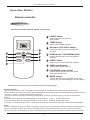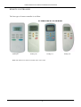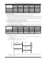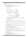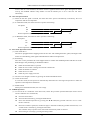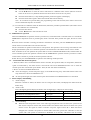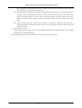
1
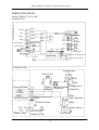
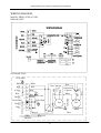
WALL MOUNTED SPLIT-TYPE AIR CONDITIONERS
DRAFT
SERVICE MANUAL
No.TE050616
Models
YKEQ
YKEQ
YKEQ
YKEQ
-
YCNQ
YCNQ
YCNQ
YCNQ
251
331
531
671
GR
GR
GR
GR
With ozone-friendly refrigerant R410A
CONTENTS
1.
2.
3.
4.
IMPORTANT NOTICE
TECHNICAL SPECIFICATION
OPERATION DETAILS
WIRING DIAGRAM
2
3
5
13
YKEQ-YCNQ 251~671 GR Air Conditioners Service Manual
IMPORTANT NOTICE
This service manual is intended for use by individuals possessing adequate
backgrounds of electrical, electronic and mechanical experience. Any
attempt to repair the appliance may result in personal injury and property
damage. The manufacturer or seller cannot be responsible for the
interpretation of this information, nor can it assume any liability in
connection with its use.
The information, specifications and parameter are subject to change due to
technical modification or improvement without any prior notice. The
accurate specifications are presented on the nameplate label.
How to order spare parts
To have your order filled promptly and correctly, please furnish the
following information:
1. Model No. with Indoor or Outdoor
2. No. in the Explosion View
3. Part Name
4. The quantity you ordered
2
YKEQ-YCNQ 251~671 GR Air Conditioners Service Manual
Technical Specifications
Model No.
Type
Control type
Rated cooling capacity
Rated heating capacity
EER for cooling
COP for heating
Moisture removal
Indoor noise level at
cooling
kW
kW
High
Med.
Low
Outdoor noise level
Electrical Data
Power supply
Rated input
V
6.0
Cooling
A
3.9
Heating
A
3.6
5.8
Cooling
W
850
1140
Heating
W
790
1140
Refrigerating System
Refrigerant/Charge
Compressor
34
32
54
YKEQ-YCNQ 331 GR
Heat Pump
Remote
3.35
3.40
2.82
2.93
1.3
38
36
34
55
1-220~240V-50HZ
Voltage Range
Rated current
Liters/h
dB(A)
dB(A)
dB(A)
dB(A)
YKEQ-YCNQ 251 GR
Heat Pump
Remote
2.45
2.82
2.88
3.24
1.0
36
R410A/540g
Rotary
Gram
Type
Model
LRA
A
MFG
Evaporator
Condenser
Expansion device
Defrosting system
Fan System
Indoor air circulation/Hi Cooling
m3/h
Indoor fan type
Cooling
rpm
Indoor fan speed
Heating
rpm
Dry
rpm
H/M/L
Sleep
rpm
Indoor fan motor output
W
Outdoor air circulation
m3/h
Outdoor fan type
Outdoor fan speed
rpm
Outdoor fan motor output
W
Connections
Refrigerant coupling
Gas
Inches
Connecting Pipe
Liquid
Inches
Connecting Wiring
Size x Core number
Drainage Pipe
Others
Suitable area
m2
Net dimensions
Indoor
mm
(W x H x D)
Outdoor mm
Indoor
kg
Net weight
Outdoor kg
Packing dimensions
Indoor
mm
(W x H x D)
Outdoor mm
Indoor
kg
Gross weight
Outdoor kg
Loading Capacity
40’/40’HC
R410A/730g
Rotary
----
----
----
----
-------
----
----
----
----
----
----
Louver fin and grooved tube type ( ϕ 7)
Corrugated fin and grooved tube type ( ϕ 9.52)
Capillary tube
Microcomputer controlled reverse system
430
Cross flow
1150/1050/950
1150/1050/950
950
950
12
2080
Propeller fan
530
Cross flow
1270/1170/1000
1250/1150/1000
950
950
12
2380
Propeller fan
860
31
860
31
Flare type
1/2
1/4
3/8
1/4
O.D 16mm
12~19
718 x 240 x 180
700 x 552 x 256
7
32
805 x 325 x 270
803 x 598 x 380
10
35
111/238/276
3
16~28
770 x 240 x 180
760 x 552 x 256
8
34
863 x 325 x 270
863 x 605 x 376
11
38
106/236/248
YKEQ-YCNQ 251~671 GR Air Conditioners Service Manual
Technical Specifications
Model No.
Type
Control type
Rated cooling capacity
Rated heating capacity
EER for cooling
COP for heating
Moisture removal
Indoor noise level at
cooling
kW
kW
High
Med.
Low
Outdoor noise level
Electrical Data
Power supply
Rated input
V
8.0
10.1
Cooling
A
Heating
A
7.5
10
Cooling
W
1750
2220
Heating
W
1650
2200
R410A/1400g
Rotary
R410A/1900g
Rotary
Refrigerating System
Refrigerant/Charge
Compressor
YKEQ-YCNQ 671 GR
Heat pump
Remote
6.70
7.50
2.73
2.98
2.6
49
47
45
58
1-220~240V-50HZ
Voltage Range
Rated current
Liters/h
dB(A)
dB(A)
dB(A)
dB(A)
YKEQ-YCNQ 531 GR
Heat pump
Remote
5.30
5.70
2.82
3.20
2.0
42
40
38
58
Gram
Type
Model
LRA
----
A
MFG
Evaporator
Condenser
Expansion device
Defrosting system
Fan System
Indoor air circulation/Hi Cooling
m3/h
Indoor fan type
Cooling
rpm
Indoor fan speed
Heating
rpm
H/M/L
Dry
rpm
Sleep
rpm
Indoor fan motor output
W
Outdoor air circulation
m3/h
Outdoor fan type
Outdoor fan speed
rpm
Outdoor fan motor output
W
Connections
Refrigerant coupling
Gas
Inches
Connecting Pipe
Liquid
Inches
Connecting Wiring
Size x Core number
Drainage Pipe
Others
Suitable area
m2
Net dimensions
Indoor
mm
(W x H x D)
Outdoor mm
Indoor
kg
Net weight
Outdoor kg
Packing dimensions
Indoor
mm
(W x H x D)
Outdoor mm
Indoor
kg
Gross weight
Outdoor kg
Loading Capacity
40’/40’HC
-------
Louver fin and grooved tube type ( ϕ 7)
Corrugated fin and grooved tube type ( ϕ 9.52)
Capillary tube
Microcomputer controlled reverse system
800
Cross flow
1060/970/880
1060/970/880
880
880
22
2100
Propeller fan
850
45
1100
Cross flow
1330/1230/1150
1330/1230/1150
1150
1150
35
3100
Propeller fan
850
76
Flare type
1/2
1/4
5/8
3/8
O.D 16mm
30~40
1033 x 313 x 202
863 x 605 x 376
14
42
1103 x 400 x 300
863 x 605 x 376
17
46
90/188/218
4
35~48
1033 x 313 x 202
902 x 650 x 307
14
56
1103 x 400 x 300
1027 x 766 x 433
17
63
63/135/157
Air Conditioner Service Manual
Operation Details
1 Remote controller
Remote controller
The remote controller transmits signals to the system.
1 ON/OFF button
Used to start and stop operation
when pressed.
2
SLEEP TIMER ON TMIER OFF
FEEL
COOL
DRY
FAN
HEAT
AUTO
HIGH
MID
LOW
SWING
3
3
5
SLEEP
FAN
7
2
TIMER
SWING
6
ON/OFF
1
8
MODE
TIMER button
Used to select TIMER operation.
UP button (TOO COOL button)
Used to increase the set room temperature
and time.
4
DOWN button (TOO WARM button)
Used to decrease the set room temperature
and time.
5
SLEEP button
Used to set or cancel sleep mode operation.
4
6
7
VANE control button
Used to adjust airflow direction.
FAN SPEED control button
Used to select the indoor fan motor speed:
Auto, High, Mid and Low.
8
MODE button
Used to select the type of operation mode: Feel,
Cooling, Dry, Fan and Heating(Only for Heat Pump).
Note: Each mode and relevant function will be further specified in following pages.
Remote Control
The remote controller is not presetted as Cooling Only Air Conditioner or Heat Pump by manufacturer.
Each time after the remote controller replace batteries or is energized, the arrowhead will flashes on the front of
Heat or Cool on LCD of the remote controller.
User can preset the remote controller type depending on the air conditioner type you have purchased as
follows:
Press any button when the arrowhead flashes on the front of Cool , Cooling Only is set.
Press any button when the arrowhead flashes on the front of
Heat , Heat Pump is set.
If you don t press any button within 10 seconds, the remote controller is preset as Heat Pump automatically.
Note :
If the air conditioner you purchased is a Cooling Only one, but you preset the remote controller as Heat Pump, it
doesn t bring any matter. But if the air conditioner you purchased is a Heat Pump one, and you preset the
remote controller as Cooling Only, then you CAN NOT preset the Heating operation with the remote controller.
5
YKEQ-YCNQ 251~671 GR Air Conditioners Service Manual
REMOTE CONTROLLER
The four types of remote controller is as follow:
For YKEQ-YCNQ 251~671 GR Models
GYKQ-05
GYKQ-10e
GYKQ-11e
Note: The function of remote controller above is the same.
6
GYKQ-12e
YKEQ-YCNQ 251~671 GR Air Conditioners Service Manual
Electronic Controller
1.
Safety Control
(1) Time Delay Safety Control
3 minutes delay for compressor---The compressor is ceased for 3minutes to balance the pressure in the
refrigeration cycle in order to protect the compressor.
2 minutes delay for 4-way valve---The 4-way valve is ceased for 2 minutes to prevent the
refrigerant-gas abnormal noise when the HEATING operation is OFF or switch to the other operation
mode.
(2) Indoor Pipe Temperature Sensor Frost Prevention Control
When the indoor pipe temperature sensor reads 0℃ or below for 5 minutes, the indoor pipe temperature
sensor frost prevention control starts. The compressor and outdoor fan stop and indoor fan operates at high
speed for 3 minutes. After that, if the indoor pipe temperature sensor reads less than 5℃ this control
prolonged until the indoor pipe temperature sensor reads 5℃ or more.
(3) High Temperature Protection Control
During HEATING operation, the outdoor fan motor and compressor are controlled by the indoor pipe
temperature to prevent the high temperature of compressor.
Outdoor fan OFF: when the indoor pipe temperature is ≥50℃
Outdoor fan ON: when the indoor pipe temperature is ≤48℃
Compressor OFF: when the indoor pipe temperature is ≥62℃
Compressor ON: when the indoor pipe temperature is ≤48℃
2.
“I Feel” Mode Operation
(1) When the “I Feel” mode is selected, the operation mode and initial set temperature are determined by the
initial room temperature at start-up of the operation except to turn off the air conditioner and operates it
again.
(2) If the mode is change to “I Feel” mode from other mode, the “I Feel” mode doesn’t operate until compressor
stop for more than 3 minutes.
Initial room temperature
Initial set temperature
COOLING
26℃ or more
24℃
DRY
20℃ to 25 ℃
18℃
HEATING for Heat Pump Type
Less than 20℃
23℃
Mode
FAN for Cooling Only Type
In the “I Feel” mode , when the controller receives the up or down single of temperature, the set
temperature can adjust by 1℃ upper or lower. The biggest you can adjust by 2℃ upper or lower.
3.
“COOLING” Mode Operation
(1) When the COOLING mode is selected without setting temperature, the system will set the set temperature at
26℃ automatically with the AUTO FAN speed.
(2) When selecting the COOLING mode operation, the system will operate according to the setting by the
remote controller and the operation is as following:
7
YKEQ-YCNQ 251~671 GR Air Conditioners Service Manual
Room Temp.
Set TEMP. +1℃
Set TEMP. -1℃
Time
4.
More than 2 min
More than 2 min
More than 2 min
More than 2 min
More than 2 min
Indoor Fan
Set Speed
Set Speed
Set Speed
Set Speed
Set Speed
Compressor
ON
OFF
ON
OFF
ON
Outdoor Fan
ON
OFF
ON
OFF
ON
“DRY” Mode Operation
(1) The system for DRY operation used the same refrigerant circle as the cooling circle.
(2) When the system operates in DRY mode ,at first it operates in cooling mode at 16℃ or 18℃ for 3 minutes.
And then, the system operates in cooling mode with low speed that regards the temperature of the room
temperature sensor reads decrease 2℃ as the set temperature. During the course of this, the fan speed
set operation is failing but the vane motor can be controlled.
5. “HEATING” Mode Operation (Only available for Heat Pump)
(1) When the HEATING mode is selected without setting temperature, the system will set the temperature at 23
℃ automatically with the AUTO FAN speed.
(2) When selecting the HEATING mode operation, the system will operate according to the setting by the
remote controller and the operation is as following:
Set Temp. +1℃
Set Temp. -1℃
Room Temp.
Time
More than 2 min
More than 2 min
More than 2 min
More than 2 min
More than 2 min
Compressor
ON
OFF
ON
OFF
ON
Outdoor fan
ON
OFF
ON
OFF
ON
(3) In HEATING mode, the indoor fan motor speed is controlled by Cold Air Prevention Control.
(4) Cold Air Prevention Control
The function is intend to prevent cold air from being discharged when the heating operation starts or
when defrosting.
The indoor fan speed will be controlled as following.
The vane angle is at the angle C(100°).
Set Speed
34℃
Low Speed
27℃
Low Speed
Temperature drop
Temperature raise
Set Speed
25℃
Stop the fan
23℃
Stop the fan
During the heating operation, if the compressor stops that it will adjust the indoor fan speed, after 30
seconds to stop the fan.
8
YKEQ-YCNQ 251~671 GR Air Conditioners Service Manual
(5) Defrost
Defrosting of the outdoor heat exchange is controlled by the microprocessor with detection by the indoor
pipe temperature sensor.
Defrost control type is according to the JC on the PCB whether is connected.
When the JC is connect on the PCB
When one of the conditions of A, Band C is satisfy, the defrosting operation stars.
A.
IPT--- indoor pipe temperature
In the condition A, it must satisfy the conditions a), b)and c) then into defrosting operation.
a) IPT1 satisfy IPT1=IPTMAX-△IPT(8℃)
b) t5≥50minutes(the compressor cumulative operation time≥50 minutes, t5 is permitted move
and lower than t1 too).
c) IPT<40℃,and keep 2 minutes.
According to the condition A enter the defrosting operation, the first defrosting operation time is
8minutes; After defrosting operation one cycle, and then judge and regulate the defrosting operation
time.
B. After the compressor cumulative operation time exceeds 120 minutes and the temperature of the IPT
is less then 35℃ for 2 minutes. When the defrosting operation time on this condition exceeds
8minutes, it will terminate.
C. After the compressor operation continuously for 20 minutes and the IPT is less than 23℃ or from
the last time of defrosting operation is 50 minutes or more interval. When the defrosting operation
time on this condition exceeds 10 minutes, it will terminal.
When the JC isn’t connected on the PCB
When the conditions of a) or b) is satisfy, the defrosting operation starts.
a) Under the heating operation, the compressor cumulative operation time exceeds 50 minutes and the
temperature of the outdoor pipe temperature sensor reads lower than -8℃
b) Under the heating operation, the compressor cumulative operation time exceeds 50 minutes, if the
indoor pipe temperature sensor reads lower than 40℃ continuously for 2minutes.
Note: If haven’t the outdoor pipe temperature sensor that use the condition b) to defrost, against
use the condition a).
Defrost terminating conditions
When the condition c) or d) is satisfy, the defrosting operation will terminal.
c) The outdoor defrost sensor reads 20℃ or more.
d) The defrosting time exceeds 10 minutes.
9
YKEQ-YCNQ 251~671 GR Air Conditioners Service Manual
Defrosting time chart
Outdoor Fan
ON
Revering Valve
OFF
ON
Compressor Relay
ON
OFF
OFF
39S
6.
ON
ON
ON
5S
OFF
Defrost Count MAX 12min
19S
15S
ON
t
“FAN” mode operation
The indoor fan motor always turns on at the set speed and the vane motor turns on at the set fettle.
7.
4-way Valve control
HEATING
ON
COOLING/DRY
OFF
The 4-way valve reverses for 5 seconds right before start-up of the compressor as following chart:
COOLING/DRY TO HEATING
HEATING TO COOLING/DRY
Compressor
4-way Valve
5s
2min
Outdoor Fan
8.
“SLEEP” mode
When the SLEEP button is pressed, the SLEEP mode is selected as following:
The indoor fan speed is set at the low speed, the power lamp and the sleep lamp is on, the temperature off
after 5 minutes.
When selecting COOLING/DRY operation with SLEEP mode, the set temperature will be raised by 1℃ 1
hour later and by 2℃ 2 hour later.
When selecting HEATING operation with SLEEP mode, the set temperature will be dropped by 1℃ 1
hour later and 2℃ 2hour later.
After the System operates in SLEEP mode for 8 hours, it will stop automatically.
9.
Fan motor control
(1) Rotational frequency feedback control
The indoor fan motor is equipped with a rotational frequency sensor, and outputs signal to the
microprocessor to feedback the rotational frequency. Comparing the current rotational frequency with the
target rotational frequency, the microprocessor adjusts fan motor electric to make the current rotational
frequency close to the target rotational frequency. With this control, when the fan speed is switched, the
rotational frequency changes smoothly.
(2) When the rotational frequency feedback signal has not output for 5 seconds (or when the microprocessor
can’t detect the signal for 5 seconds), the fan motor is regarded locked-up. Then the electric current to the fan
10
YKEQ-YCNQ 251~671 GR Air Conditioners Service Manual
motor is shut off. 10 seconds later, the electric current is applied to the fan motor again. During the fan motor
lock-up, the POWER indicator lamp flashes on and off 6times/cycle or E6 to show the fan motor
abnormality.
10. Auto Fan Speed Control
(1) When the auto fan speed is selected, the indoor fan motor speed is automatically controlled by the room
temperature and the set temperature.
(2) In COOLING mode, the indoor fan motor operates as following:
Fan Speed
Hi
Me
Lo
Room temperature minus set temperature:
1℃
2℃
4℃
(3) In HEATING mode, the indoor fan motor operates as following;
Fan Speed
Hi
Mi
Lo
Room temperature minus set temperature
1℃
2℃
4℃
11. Auto Vane Operation control
(1) Vane motor drive
The unit is equipped with a stepping motor for the vane. The rotating direction, speed, and angle of the
motor are controlled by pulse signal transmitted from indoor microprocessor.
(2) Positioning
The vane is once pressed to the vane stopper below to confirm the standard position and then set to the
desired angle. The positioning is decided as follows:
When the ON/OFF button is pressed.
When the vane control is change from AUTO to MANUAL.
When the SWING is finished.
When the test run starts.
When the power supply turns ON.
(3) The auto vane changes as follows by pressing the VANE CONTROL button.
(4) VANE AUTO mode
In vane auto mode, the microprocessor automatically determines the vane angle and operation to make the
optimum room-temperature distribution.
(5) SWING mode
When presses the SWING button, the vane swings.
12. TIMER Operation
(1) To activate the air conditioner at the desire time, follow the procedure specified below(the remote control
and air conditioner are switched off):
Press the Timer button.
Select the desired mode by pressing the Mode button.
Select the desired temperature by pressing the ▲ ▼ button(only possible when the ‘cool’ or ‘heat’
mode is selected).
Select the ventilator speed (low, medium or high) or automatic mode(only possible when the feel, Cool
or Heat mode is selected) by pressing the Fan button.
The ventilator always operates in the Auto mode when the Dry mode is selected.
Select Swing or no Swing by pressing the Swing button.
11
YKEQ-YCNQ 251~671 GR Air Conditioners Service Manual
Press the Timer button(‘h’ flashes).
Use the ▲▼ button to select the time at which the air conditioner must activate (between 0 and 10
hours can be set at every half hour-between 10 and 24 hours can be set at every hour).
Press the Timer button (‘h’ stops flashing) and the preset time appears in the display.
Press the Timer button again to delete the selected data from the memory.
Note : If no buttons are pressed during the programming of the timer function, thee remote control will
switch off automatically after 10 seconds.
(2) To switch the air conditioner off at the desired time, follow the procedure specified below (the remote control
and air conditioner are switched off):
Press the timer button.
Use the ▲▼ button to select the time at witch.
13. EMERGENCY Operation
When the EMERGENCY Operation switch is pressed once, COOLING mode is selected and if in 3 seconds the
EMERGENCY Operation switch is pressed again, mode is selected. Then pressed once again, the unit is switch
off.
When the remote controller is missing, has failed or the batteries run down, press the EMERGENCY Operation
switch on the front of the indoor unit. The unit will start.
The first 30 minutes of operation will be the test run operation. The operation is for servicing. The indoor fan runs
at high speed and the system is in continuous operation. The thermostat is ON and the timer is reset to normal.
After 30 minutes of test run operation the system shifts to AUTO COOLING/HEATING mode, and the indoor fan
runs in automatic speed. The operation continues unit the EMERGENCY operation switch is pressed or a button
on the remote controller is pressed, the normal operation will start.
NOTE: Do not press the EMERGEMCY Operation switch during normal operation.
14.
AUTO RESTART Function(Option)
1.When the indoor unit is controlled with the remote controller, the operation mode, set temperature, and the fan
speed are memorized by the indoor electric control PCB. The AUTO RESTART function sets to work the
moment power has restored after power failure. Then, the unit will restart automatically.
2. How to set the AUTO RESTAR function.
Press the emergency switch and power supply to the PCB following, keep 10seconds and the buzzer will
beep three times. The AUTO-RESTAR is set.
Do the operation again, the buzzer will beep four times and the AUTO-RESTAR function is cancelled.
15. Failure Display and Handling
a)
Failure Display
When the controller is failure, the buzzer will voice long for three times, and displays the failure from the
failure lamp.
b)
Failure Code
If have the digital pipe that display the failure code for digital pipe, or display for the run lamp.
c)
Type of failure
The lamp flash
Display of digital pipe
The failure of room temperature sensor
Once/cycle
E1
The failure of indoor pipe temperature sensor
Twice/cycle
E2
The failure of indoor fan motor
6 times/cycle
E6
Failure Handling
When the room temperature sensor or the indoor pipe temperature sensor is failure, the system will be
shut off, the compressor will be OFF, and the outdoor fan and the indoor fan will be OFF. The system
doesn’t receive the signal of remoter controller except the signal of shut off it. When the failure
disappear, the controller can operate in normal mode. before this, presses the “ON/OFF” to start the
system, and it will operate in COOLING or HEATING for 30 minutes, and follows shut off. During
12
YKEQ-YCNQ 251~671 GR Air Conditioners Service Manual
this, it displays the failure and the protection is failing. You must be given the electric again to operate
it. In the failure, you can operate the FAN mode.
When the outdoor protects in the COOLING or DRY, the outdoor unit stops, the indoor fan operates in
set speed ; and in the HEATING, the outdoor unit stops, the indoor fan operates in cold air prevention
control. The system doesn’t receive the signal of remoter controller except the signal of shut off it.
When the system check the voltage is 220V and the delay control is finished, it operates at normal
again.
When the indoor fan motor is failure, the compressor is stopped, the outdoor fan and indoor fan is
stopped and display the failure. The system doesn’t receive the signal of remoter controller except the
signal of shut off it.
d)
Display Of The Control
In the display board the lamp from left is the POWER lamp(Red), the SLEEP lamp(Yellow), the TIMER
lamp(Yellow), the RUN lamp(Green).
g) When gives the control electric, the buzzer voices a long for 0.3 second per cycle.
13
YKEQ-YCNQ 251~671 GR Air Conditioners Service Manual
WIRING DIAGRAM
MODELS: YKEQ-YCNQ 251, 331 GR
INDOOR UNIT:
PCB
P2-1
P5
P4
CN2
Transformer
YLW/GRN
Blue
Yellow
Red
Brown
P2-2
Display PCB
Room Temp. sensor
Pipe Temp. sensor
NO 4
K1
COM 3
CN8
TH1
CN5
CN4
YLW/GRN
Blue
Yellow
Red
Brown
N
3
2
1
Blue
YLW/GRN
Brown
CN6
TH2
N
3
2
1
Power Supply
CN3
Outdoor
Unit
CN1
Evaporator
θ Protecter
M
Vane Motor
M
Fan Motor
Indoor Unit
OUTDOOR UNIT
Compressor
1
2
3
N
White
Black
CM
R(M)
C
S
Red
Blue
θ
Protecter
Blue
Yellow/Green
Orange
Brown(White)
Red
Yellow
Blue
Yellow/Green
Blue
Blue
4-way Vane
M
Indoor Unit
Compressor
Capacitor
Blue
Fan Capaciter
Blue
Yellow/Green
Fan Motor
Outdoor Unit
14
YKEQ-YCNQ 251~671 GR Air Conditioners Service Manual
WIRING DIAGRAM
Brown
Red
Yellow
Blue
Yellow/Green
Yellow/Green
Blue
Brown
White
Red
Yellow
Blue
Yellow/Green
P4
P3
P5
AC(N) P1
P2-1
Relay
To The Outdoor Unit
MODEL:YKEQ-YCNQ 531 GR
INDOOR UNIT:
PCB
CN1
CN8
FM
Fan Motor
CN5-1
SM
CN5-2
CN7 CN6
SM
Brown
Vane Motor
Room Temp. Sensor
Display PCB
To O.P.T
Transformer
CN3
P9-1
P9-2
Yellow/Green
Blue
CN2
Pipe Temp. Sensor
OUTDOOR UNIT:
Compressor
1
2
3
N
White
Black
Blue
Yellow/Green
CN7 JUNCTION
TH3
θ
R(M)
C
S
Red
Blue
Inside/Outside Compressor
Protecter
Capacitor
M
JUNCTION
Indoor Unit
CM
Orange
Brown(White)
Red
Yellow
Blue
Yellow/Green
Blue
Blue
Valve Coil
Blue
Fan Capaciter
Blue
Yellow/Green
Fan Motor
Outdoor Unit
15
YKEQ-YCNQ 251~671 GR Air Conditioners Service Manual
WIRING DIAGRM
MODEL: YKEQ-YCNQ 671 GR
INDOOR UNIT:
FM
SM
SM
OUTDOOR UNIT:
YLW/GRN
Brown
Blue
To Power Supply
YLW/GRN
N Blue
Valve Coil
L Brown
YLW/GRN
FM
L
N
Fan Motor
Blue
Relay
Brown
Junction
O.P.T
16
White
Blue
C2
Blue
Red
Blue
Red
Brown
3
Blue
Fan Capacitor
C1
Compressor
Capacity
YLW/GRN
Blue
2
White
Red
Yellow
1
Yellow
Red
To Indoor Unit
White
CS R
FM
Compressor
Motor