1
YAMAHA
MUSIC SYNTHESIZER
SUPPLEMENTAL MARKING INFORMATION
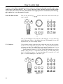
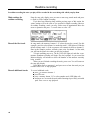
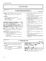
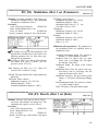
Yamaha Digital Musical Instrument Products will have either a label similar to the graphic shown below or a
molded/stamped facsimile of the graphic on its enclosure. The explanation of these graphics appears on this page.
Please observe all cautions indicated.
The exclamation point within an equilateral triangle is intended to alert the user to
the presence of important operating and
maintenance (servicing) instructions in the
literautre accompanying the product.
CAUTION: TO REDUCE THE RISK OF ELECTRIC SHOCK.
DO NOT REMOVE COVER (OR BACK).
NO USER-SERVICEABLE PARTS INSIDE.
REFER SERVICING TO QUALIFIED SERVICE PERSONNEL.
The lightning flash with arrowhead symbol, within an equilateral triangle, is
intended to alert the user to the presence of
uninsulated "dangerous voltage" within
the product's enclosure that may be of sufficient magnitude to constitute a risk of
electric shock to persons.
This information on safety is provided to comply with U.S.A. laws, but should be observed by users in all countries.
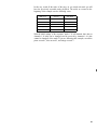
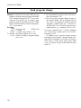
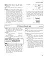
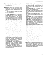
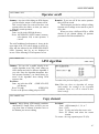
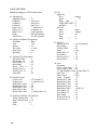
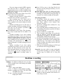
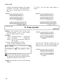
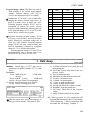
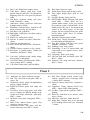
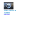
JOB TABLE
YAMAHA
#230
AFM element data
#200
#201
Voice mode
Voice common data
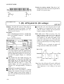
01. AFM algorithm
01. AWM waveform set
#257
Song edit job
#232
02. AWM EG
#258
01. Quantize
#601
01. Copy pattern
#701
Inpt
#233
03. AWM output
#259
02. Modify gate time
#602
02. Get pattern
#702
04. AWM sensitivity
#260
03. Modify velocity
#603
03. Put pattern
#703
#261
04. Crescendo
#604
Data #262
05. Transpose
#605
#263
06. Thin out
#606
01. Receive event
#706
#264
07. Erase event
#607
02. Output channel
#707
01. Element level
#202
#203
03. Element note shift
#204
02. AFM oscillator
04. Element note limit
#205
03. AFM operator EG
05. Element velocity limit
#206
#236
Each
~237
06. Element dynamic pan
#207
#238
#208
08. Random pitch
#209
Graphic #234
#210
10. Effect set
#211
05. AFM sensitivity
#212
06. AFM LFO
Data #213
02 Modulation
effect 1 set
Parm #214
Modulation
Data #215
effect 2 set
Parm #216
Reverb
Data #217
effect 1 set
Parm #218
Reverb
Data #219
effect 2 set
Parm #220
11. Micro tuning set
#221
03
04
05
01 Micro tuning edit
#222
02 Micro tuning data
#223
03 Micro tuning name
#224
12. Controller set
13. Voice name
All
02
Cutoff scaling
03
Cutoff EG
06. AWM pitch EG
EG
07. AWM filter
01
Cutoff frequency
02
Cutoff scaling
03
Cutoff EG
#608
03. MIDI control
#708
09. Move clock
#609
04. Accent level
#709
Flt2
#267
10. Copy measure
#610
05. Clock/beat
Flt1
#268
~269
11. Erase measure
#611
12. Delete measure
Clear pattern (One)
#612 Clear pattern (All)
#270
13. Create measure
#613
Sw
#246
EG
#247
15. Initialize AWM element
—
#248
16. Recall voice
—
Flt2
#251
Flt1
#252
~253
Flt2
#254
~255
15. Initialize AFM element
—
16. Recall voice
—
Flt2
Drum set data
~271
#272
Song setup
02. Output channel
#619
03. MIDI control
#620
04. Accent level
#621
05. Clock/beat
#622
#211
03. Effect set
(see Voice Common Data) #212
~220
04. Controller set
#275
05. Voice name
#229
08. Recall voice
—
Pan
#227
Othr
#228
Song name
01 Voice select
02. Voice volume
03. Voice tuning
1 ~ 8 #402
06. Voice output
1 ~ 8 #410
9~16 #403
group select
9 ~ 1 6 #411
1 ~ 8 #404
1 ~ 8 #406
9~16 #407
02
Effect mode select
Modulation
effect 1 set
04
05
Reverb
effect 1 set
Reverb
effect 2 set
#412
07. Effect set
01
Modulation
effect 2 set
1 ~ 8 #408
9 ~ 1 6 #409
#401
9~16 #405
04. Voice note shift
05. Voice static pan
#413
Data #414
Parm #415
#623
System utility
08. Multi name
Data #416
Parm #417
Data #418
Parm #419
Data #420
Parm #421
#422
#710
#711
#712
#800
01. Master tuning
#801
02. Velocity set
#802
03. Controllers
#803
04. Edit confirm
#804
05. Greeting message
MIDI utility
#805
#806
01. Channel set
#807
02. Program change
#808
03. Bulk dump
Card utility
03
#400
#617
#274
#226
—
#616
02. Wave data set
Mod
16. Recall voice
16. Clear song
#618
—
—
#615
01. Receive event
07. Initialize voice
15. Initialize voice
#614
#273
#225
#229
14. Mix track
15. Erase track
01. Voice volume
PB
Multi data
#704
#705
08. Note shift
#245
#250
04. Put chain pattern
Pattern setup
#700
#266
Sub
Flt1
Pattern edit job
#265
244
#249
#601
Flt1
Main
08. AFM filter
Cutoff frequency
05. AWM LFO
#242
#243
07. AFM pitch EG
01
~240
Each #241
output
09. Portamento
01 Effect mode select
#235
All
04. AFM operator
#256
Extn
Form #231
02. Element detune
07. Output group select
AWM element data
#809
#812
01. Save to card
#813
02. Load from card
#814
03. Format card
Disk utility
01. Save to disk
#815
#816
—
02. Load from disk
#817
03. Format disk
#818
04. Backup disk
#819
05. Rename file
—
15. Initialize multi
—
06. Delete file
—
16. Recall multi
—
07. Disk status
—
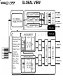
YAMAHA
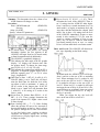
GLOBAL VIEW
Element Level
Element Detune
Note Shift
Velocity Limit
Element Pan
Output Select
Random
Portamento
Effect Select
Micro Tune
Controller
Voice Name
Init
Recall
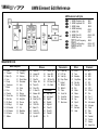
YAMAHA
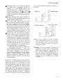
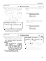
AWM Element Edit Reference
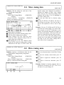
AWM element edit jobs
1.
2.
3.
4.
5.
6.
7.
AWM
AWM
AWM
AWM
AWM
AWM
AWM
Waveform Set
Amplitude EG
Output
Sensitivity
LFO
Pitch EG
Filter set
Cutoff frequency
Cutoff scaling
Cutoff EG
#257
#258
#259
#260
#261
#262...263
#264
#265
#266...267
#268...271
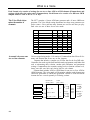
Waveform list
Multi-sampled
1
2
3
4
5
6
7
8
9
10
11
12
13
14
15
16
17
Piano
Trumpet
Mute Tp
Horn
Fluqel
Trombone
Brass
Flute
Clarinet
Tenor Sax
Alto Sax
Gtr Steel
EG Sngl
EG Humbk
EG Harmo
EG mute
E.Bass
18
19
20
21
22
23
24
24
25
26
28
29
30
31
32
33
Thumping
Popping
Fretless
Wood Bass
Shamisen
Koto
Violin
Pizz
Strings
Anlg Bass
Anlg Brs
Chorus
ltopia
Vib
Marimba
Tubular
Waves
34
35
36
37
38
39
40
41
42
43
44
45
46
47
48
49
50
Cele WV
Harpsi WV
E.P. WV
Pipe WV
Organ W V
Tuba WV
Picco WV
S. Sax WV
Basson WV
Reco WV
Mute Tp WV
Gut WV
12Str WV
Bass WY
Cello WV
Contra WV
Xylo WV
Transients
51
52
53
54
55
56
Gloch WV
Harp WV
Sitar WV
Stl Drm WV
Mt Reed WV
Oh Attack
Oscillator
57
58
59
60
61
62
63
64
65
Anlg Saw1
Anlg Saw2
Digital1
Digital2
Digital3
Pulse10
Pulse25
Pulse50
Tri
66
67
68
69
70
71
72
73
74
75
76
77
Piano Np
E.P. Np
Vibe Np
Dmp Piano
Bottle 1
Bottle 2
Bottle 3
Tube
Vocal Ga
Vocal Ba
Sax trans
Bow trans
Other
78
79
80
81
82
83
84
85
86
87
88
89
90
91
92
Bulb
Tear
Bamboo
Cup Echo
Digi Atk
Temp Ra
Giri
Water
Steam
Narrow
Airy
Styroll
Noise
Bell mix
Haaa
Drumset
93
94
95
96
97
98
99
100
101
102
103
104
105
106
107
108
109
110
111
112
BD1
BD2
BD3
BD4
SD1
SD2
SD3
SD roll
Rim
Tom 1
Tom 2
HH closed
HH open
Crash
Ride
Claps
Cowbell
Tambrn
Shaker
Analg Perc
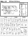
YAMAHA
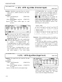
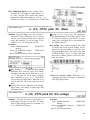
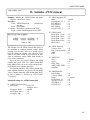
AFM Element Edit Reference
AFM element edit jobs
1. Algorithm
(Form)
(Extr)
(Inpt)
2. Oscillator
3. AFM EG
4. AFM operator output
5. AFM sensitivity
6. AFM LFO
(Main)
(Sub)
7. AFM pitch EG
8. AFM filter
Cutoff frequency
Cutoff scaling
Cutoff EG
#231
#232
#233
#235
#236...239
#241...242
#243
#244
#245
#246...247
#248
#249
#250...251
#253...255
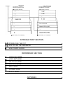
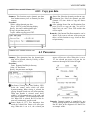
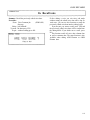
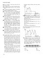
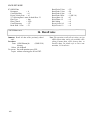
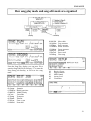
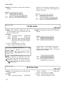
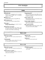
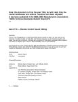
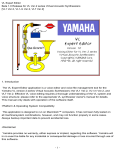
* Keyboard *
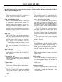
SEQUENCER
The sequencer is always in
either Song or Pattern mode.
TONE GENERATOR
The tone generator is always in
either Multi or Voice mode.
Song mode (16 tracks)
Multi mode (16 voices)
Voice mode (1,2 or 4 elements)
Voice mode (1,2 or 4 elements)
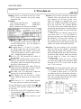
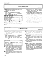
INTRODUCTORY SECTION
INTRODUCING THE SY77
n
HOW TO USE THE SEQUENCER
n
HOW TO EDIT A VOICE
n
REFERENCE SECTION
VOICE PLAY MODE
n
VOICE EDIT MODE
n
MULTI PLAY MODE
n
MULTI EDIT MODE
n
SONG MODE
n
PATTERN MODE
n
UTILITY MODE
n
APPENDIX
n
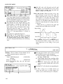
Thank you for purchasing the Yamaha SY77 digital synthesizer. The SY77 is the first of a new generation of
Yamaha synthesizers featuring the new Realtime Convolution and Modulation (RCM) hybrid tone generation
system, which uses Advanced FM (AFM) tone generation and Advanced Wave Memory (AWM) tone generation in conjunction with realtime digital filtering.
The SY77 can function as up to 16 independent synthesizers with dynamically allocated voices, and includes
an on-board 16-track 99-pattern sequencer.
To take full advantage of the SY77 and enjoy long and trouble-free use, please read this manual carefully.
How to use this manual
This manual is divided into three sections; an introductory section, a reference
section, and an appendix.
Introductory section: This section contains the information you need to start
using your SY77 right away.
l Introducing the SY77: Please be sure to read this section. It will tell you
how to play the sounds, about the main features of the SY77, and about
basic operation.
l How to use the sequencer: This explains how to use the built-in
sequencer to record your own song of up to 16 parts, with the SY77 functioning as up to sixteen independent instruments.
l How to edit a Voice: Read this when you want to modify a voice or create
a completely new voice.
Reference section: This section contains a full explanation of all the SY77’s
functions. Once you have worked through the introductory section and are
comfortable with basic operation, glance through this section to get an idea
of the SY77’s capabilities. Refer to the details when necessary.
Appendix: This section contains technical information that may be of interest to
advanced users or programmers.
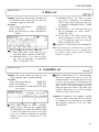
Conventions in this manual
In order to present information as clearly as possible, the following conventions
are used in this manual.
l The names of front panel buttons and controls are set in small capital type;
e.g., press the EDIT button.
l Italics are used mainly when referring to a section in this manual; e.g., for
details refer to AFM element job 5. AFM sensitivity.
l Most of the LCDs in the SY77 have a unique Page Jump number to which you
can jump by pressing JUMP and entering the number. These numbers will be
prefixed by a “#” sign; e.g, JUMP #312.
l Function names will be capitalized when they first occur or when necessary
for emphasis, but will be uncapitalized in subsequent occurrences; e.g., adjust
the LFO Speed ... after adjusting the LFO speed, ...
l The beginning of each two-page subsection in the introductory section contains a short abstract or summary of the entire subsection, printed in bold
type.
l Three periods between two numbers are used to indicate that a parameter
can be set to any value in this range; e.g., Velocity Sensitivity (-7...+7).
Since some parameters can be set to negative values, this avoids the possibility of confusing a dash with a minus sign.
CONTENTS
INTRODUCTORY SECTION
INTRODUCING THE SY77
How to setup and play
How to load and play the disk demo songs
How to record a song
About the SY77: RCM hybrid synthesis
About the SY77: AFM and AWM voices
About the SY77: filter, pan, and effects
About the SY77: multi-timbral sequencing
Front panel: left side
Front panel: right side
Rear panel
How to move around: job directories
How to move around: the jump function
How to enter data
How to use the numeric key pad
3
4
6
8
10
12
14
16
18
20
22
24
26
28
30
HOW TO USE THE SEQUENCER
How the sequencer controls the tone
generator
Set up a multi
Create rhythm patterns
33
34
36
38
Place the patterns in the pattern track
Realtime recording
Punch-in recording
Song editing
Using a song edit job
Saving your sequence to disk
40
42
44
46
48
50
HOW TO EDIT A VOICE
What is a voice
What is an AWM element
The basics of FM synthesis
What is an AFM element
The process of voice editing
How voice edit mode is organized
Simple editing: reverb (Effect)
Simple editing: tone (Filter)
Simple editing: vibrato (LFO)
Simple editing: using a controller
Simple editing: attack (EG)
How to name and store your new voice
How to edit a drum voice
53
54
56
58
60
62
64
66
68
70
72
74
76
78
REFERENCE SECTION
VOICE PLAY MODE
Voice select
Voice directory
Copy voice
Controller view
Send program change
83
84
84
85
85
86
VOICE EDIT MODE
Compare
Store voice
Element on/off
Element select
Voice mode select
Common data
Common data job directory
1. Element level
87
89
89
90
90
91
92
92
92
i
2. Element detune
3. Note shift
4. Note limit
5. Velocity limit
6. Element dynamic pan
6.0 Dynamic pan edit
6.0.1 Copy pan data
6.1 Pan source
6.2 Pan EG
6.3 Pan name
7. Output group select
8. Random pitch
9. Portamento
10. Effect set
10.1 Effect mode select
10.1.1 Copy voice effect
93
93
94
95
95
96
97
97
98
99
99
99
100
100
101
102
10.2 (Fl) Modulation effect 1 set (Data)
10.2 (F2) Modulation effect 1 set
(Parameters)
10.4 (Fl) Reverb effect 1 set (Data)
10.4 (F2) Reverb effect 1 set
(Parameters)
11. Micro tuning
11.0 Micro tuning edit
11.0.1 Copy micro tuning
11.1 Micro tuning data
11.2 Micro tuning name
12. (Fl) Controllers set (Pitch bend)
12. (F2) Controllers set (Modulation)
12. (F3) Controllers set (Pan)
12. (F4) Controllers set (Other)
13. Voice name
15. Initialize voice
16. Recall voice
AFM element data
AFM element job directory
Operator on/off
AFM algorithm
Copy element
Copy operator
1. (F1) AFM algorithm (Form)
1. (F2) AFM algorithm (External input)
1. (F3) AFM algorithm (Input level)
2. AFM oscillator
3. (Fl) AFM operator
EG (Each operator)
3. (F2) AFM operator EG
(All operators)
4. (Fl) Operator output (Each)
4. (F2) AFM operator output (All)
5. AFM sensitivity
6. (Fl) AFM LFO (Main)
6. (F2) AFM LFO (Sub)
7. (Fl) AFM pitch EG (Switch)
7. (F2) AFM pitch EG (EG settings)
8. AFM filter
8.0 Copy filter
8.1 Cutoff frequency
8.2 Cutoff scaling
8.3 Cutoff EG
15. Initialize AFM element
16. Recall voice
AWM element data
AWM element job directory
Copy element
1. AWM waveform set
2. AWM EG
3. AWM output
4. AWM sensitivity
102
103
103
104
106
108
108
109
109
110
110
111
112
113
113
115
116
116
117
117
117
118
118
120
120
121
123
125
125
126
127
127
128
129
130
131
131
131
133
134
135
137
138
138
138
139
141
142
143
5. AWM LFO
6. (Fl) AWM pitch EG (Data)
6. (F2) AWM pitch EG (EG settings)
7 . AWM filter
15. Initialize AWM element
16. Recall voice
Drum set data
Drum set job directory
1. Voice volume
2. Wave data set
3. Effect set
4. Controller set
5. Voice name
7. Initialize voice
8. Recall voice
144
145
145
146
147
148
149
149
149
150
151
151
152
152
153
MULTI PLAY MODE
Multi select
Multi directory
Copy multi
Send program change
155
157
157
158
158
MULTI EDIT MODE
Compare
Store multi
Multi edit job directory
1. Voice select
2. Voice volume
3. Voice tuning
4. Voice note shift
5. Voice static pan
6. Voice output group select
7. Effect set
8. Multi name
15. Initialize multi
16. Recall Multi
159
161
161
161
162
163
163
164
164
165
165
166
166
167
SONG MODE
How song play mode and song edit
mode are organized
Song play
Song record
Realtime recording
Punch-in recording
Step recording
Song edit
Song edit (graph)
Song edit (data change)
Song edit (data insert)
Chain pattern
Song edit jobs
1. Quantize
2. Modify gate time
169
171
172
174
175
176
177
179
179
180
181
182
185
186
186
ii
3. Modify velocity
4. Crescendo
5. Transpose
6. Thin out
7. Erase event
8. Note shift
9. Move clock
10. Copy measure
11. Erase measure
12. Delete measure
13. Create measure
14. Mix track
15. Erase track
16. Clear song
Song setup jobs
1. Receive event
2. Output channel
3. MIDI control
4. Accent level
5. Clock/Beat
Song name
PATTERN MODE
How pattern play mode and pattern edit
mode are organized
Pattern play
Pattern record
Pattern realtime record
Pattern step record
Pattern edit
Pattern edit jobs
187
188
189
189
190
190
191
191
192
193
193
194
194
195
196
196
197
197
197
198
199
201
203
204
205
206
207
209
210
1. Copy pattern
2. Get pattern
3. Put pattern
4. Put chain pattern
Pattern setup jobs
Clear pattern
UTILITY MODE
System utility
1. Master tuning
2. Velocity set
3. Controllers
4. Edit confirm
5. Greeting message
MIDI utility
1. Channel set
2. Program change
3. Bulk dump
Card utility
1. Save to card
2. Load from card
3. Format card
Disk utility
1. Save to disk
1.1 Save To Disk filename
2. Load from disk
3. Format disk
4. Backup disk
5. Rename file
6. Delete file
7. Disk status
210
211
211
212
213
214
215
217
217
217
219
220
220
221
221
222
223
225
225
226
226
227
227
228
229
230
231
231
232
232
APPENDIX
Explanation of the preset voices
Preset 1
Preset 2
Using RCM hybrid synthesis
Suggestions for using AWM + AFM
(Voice modes 9 & 10)
Error messages
MIDI
Data card
iii
238
238
239
242
242
244
244
244
Wave card
Disk
Sequencer and display
Battery
Other
Multi data blank chart
Specifications
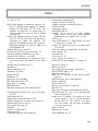
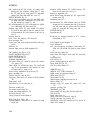
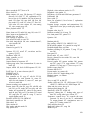
Index
244
245
245
245
246
247
248
249
iv
1
2
INTRODUCING THE SY77
This section will tell you how to play the sounds, introduce you to the main features of the
SY77, and explain basic operation.
Contents of this section
How to setup and play
How to load and play the disk demo songs
How to record a song
About the SY77: RCM hybrid synthesis
About the SY77: AFM and AWM voices
About the SY77: filter, pan, and effects
About the SY77: multi-timbral sequencing
Front panel: left side
Front panel: right side
Rear panel
How to move around: job directories
How to move around: the jump function
How to enter data
How to use the numeric key pad
Page
4
6
8
10
12
14
16
18
20
22
24
26
28
30
3
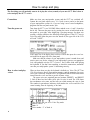
How to setup and play
The first thing you will probably want to do is play the voices (sounds) of your new SY77. Here’s how to
select and play the SY77’s voices.
Connections
Make sure that your amp/speaker system and the SY77 are switched off.
Connect the rear panel output OUTPUT 1/1+2 jacks (L/MONO and R) to the inputs
of your amp/speaker system. Or, if you are using a set of stereo headphones,
plug them into the rear panel PHONES jack.
Turn the power on
Turn down the SY77’s two VOLUME sliders marked OUTPUT 1 and 2, located at
the far left. Then turn the power on by pressing the POWER switch located on the
rear panel to your right. After displaying a greeting message for about two
seconds, a display similar to the following should appear. If the SY77 was in
Voice Play mode when the power was last turned off, the upper left of the LCD
will read “VOICE”.
If the upper line of the display does not show VOICE then press the VOICE button located at the upper left of the front panel.
Make sure that the volume of your amp/speaker system is turned down, and
turn its power on. Set the volume of your amp/speaker system to an appropriate
level, and gradually raise the SY77’s OUTPUT 1 and 2 sliders slider while playing
the keyboard. If you don’t hear anything, re-check the connections, and make
sure that your amp/speaker system is functioning correctly.
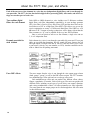
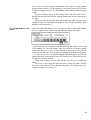
How to select and play
voices
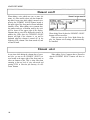
What you hear when you play the keyboard is defined as a Voice. The SY77 has
128 voices that are preset in permanent memory, and 64 memories for you to
store your own newly created voices. An optional RAM or ROM card can be
inserted into the VOICE card slot to provide 64 more voices.
The preset voices are organized into two locations; PRESET 1 and PRESET
2. Each of these has four banks (A-D) with 16 voices in each. The LCD shows
the ten-character voice name, and also tells you which memory the voice is from
The number in parentheses indicates what number the voice would be if we
started counting from the beginning of the bank.
This indicates that you are in Voice Play mode.
Memory PRESET 1.
Bank A.
Voice number “1” of bank A.
4
If we count from the beginning of the bank, this is Voice number 1.
The voice name is “GrandPiano”.
You will learn about the other parts of the display later. For now, here’s how to
select voices.
1. Select the voice memory; INTERNAL, CARD (only if a card is inserted into the
DATA slot), PRESET 1, or PRESET 2. The selected LED will light.
2. Select a bank A, B, C, or D. The selected LED will light.
3. Select a voice 1-16. The selected LED will light, and the LCD display will
show the newly selected voice name.
Notice that the voice does not actually change until you specify the number 1-16.
If you want to play a different voice in the same bank, simply specify a different
number 1-16. There’s no need to re-select the voice memory and the bank each
time.
Go ahead and try out each of the preset voices. When you are ready to learn
more about the SY77, continue reading.
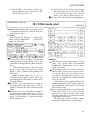
PRESET 2 (64 voices)
PRESET 1 (64 voices)
#
Bank A
Bank B
Bank C
Bank D
#
Bank A
Bank B
Bank C
Bank D
1
GrandPiano
Dyna Grand
Mute Trmpt
Tutti Orch
1
SaxSection
Violin
Shamisen
Brass Orch
2
Arianne
MW2Grand
FlugelHorn
Trad E.Pno
2
Folk 2 Gtr
Pizzicato
Koto
Millenium!
3
Dyno E.Pno
8ba Piano
Big Band
Full E.Pno
3
Humbucker
Contrabass
Sitar
Catharsis
4
Alto Sax
Rock Pno
Brass1 Sct
Bop Organ
4
Singlecoil
Air Cello
Steel Drum
MethylMist
5
BrasChoral
Chorus Pno
1980 Brass
Warm Organ
5
12stGuitar
SilkString
Harp
Voyager
6
Folk 1 Gtr
BigChordEP
Star Brass
Deep Organ
6
Guit Guitar
Obie Strgs
Accordion
Inferno
7
Triton
Ice Piano
Anna Brass
Pan Flute
7
Mute E.Gtr
SizIeStrgs
Harmonica
Valkyrie
8
FrenchHorn
Dark E.Pno
BrashBrass MW2Feedbck
8
JazzGuitar
Ah Choir
Harpomatic
Syren Song
9
MW2TackPno
Wet Clavi
Soft Brass
9
Pick Bass
Spirits
Ravi Clavi
Anna Sweep
10
Wood Bass
TightClavi
DigiSwpBrs Thumb Bass
10
Fretless B
Chor Meist
Forest
SyncanSyn
11
ChamberStr
Celesta
Brass2 Sct
Sync Bass
11
FingerBass
Vibes
Satin Bell
AnnaPad
12
Jazz Organ
Harpsichrd
Soft Sax
FullString
12
Syn Bass
Marimba
Mr.Lucky
Gosh!
13
Nasty Saw
Full Organ
Tenor Sax
WideString
13
Plastic Bs
Pluck Echo
Mini Lead!
Debonair
14
Metamonics
Pipe Organ
Flute
ConvoStrgs
14
Mini Bass
Bah Mallet
Keytar
HiddenRing
15
16
ltopia
Wild Sing
Distort5th
Solo Trmpt
Clarinet
Oh Choir
15
Boppa Bass
Oz Hammer
SoloFlight
Drum 1
DualTrmpt
Reed Piper
Orchestra
16
BreathBass
Ice Chime
Wayfarer
Drum 2
5
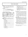
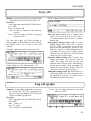
How to load and play the disk demo songs
The disk included with the SY77 contains demo songs which take advantage of its capabilities. Here’s how
to load and play the songs.
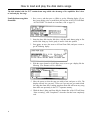
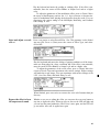
Load the demo song data
from disk
1. Press UTILITY, and then press F4 (Disk) to get the following display. (If you
have been editing voice or multi data, the top line of the LCD will blink
“AUTO-STORE”. For details on Auto-Store, refer to page 63.)
2. Insert the demo disk into the disk drive, with the metal shutter going in first
and the label facing up. Push it gently in until it clicks into position.
3. Press once to move the cursor to 02:Load From Disk, and press
get the following display.
4. With the cursor located at 01:All Data, press
following. (The filenames will be different.)
ENTER
ENTER
to
to get a display like the
5. Move the cursor to select the song you wish to hear, and press F8 (Go). The
display will ask “Are you sure”. Press YES if you are sure you want to load
the song data from disk. Loading song data from disk will erase any song
data which was previously in the SY77 sequencer memory.
6. While the data is being read from disk, the bottom line of the LCD will show
“Now executing”, and “Completed!” when the data has been completely
read.
6
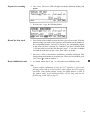
Enter song play mode and
playback the song
7. Press SONG to make the SONG LED light red. A display like the following will
appear. (The song name and other details will depend on the song you have
selected.)
8. Press PLAY and the playback will begin. When the song ends you automatically return to measure 1.
9. To stop playback during the song press STOP. To resume playback from
where you stopped, press START. Or, use and
to move to another measure before pressing START. To return to the beginning of the song press
How to load another song
To load another song from disk, repeat the procedure from step 1. Or, press
and then ENTER to jump directly to step 3.
JUMP, 8, 1, 7
How to load other demo
disks
The demo disk included with the SY77 contains both synthesizer and sequencer
data, and must be loaded by selecting 01:All Data in step 4. If you have other
demo disks, refer to the package to see what type of data the disk contains, and
select the appropriate type in step 4.
7
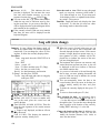
How to record a song
The SY77 can function as 16 independent synthesizers, and also contains a built-in 16 track sequencer.
This allows you to create sixteen-part compositions without using any other equipment. This section will
explain the simplest way to record a multi-part song.
Clear the sequencer
memory
Select a Multi
1. Turn the SY77 power off, and all data in the sequencer memory will be
cleared.
In multi mode the SY77 can function as 16 independent synthesizers. The multi
settings determine which voices are used.
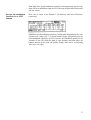
2. Press MULTI to enter multi mode. The
similar to the following will appear.
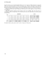
3.
Number
01
02
03
04
Multi Name
POP
ROCK 1
JAZZ 1
JAZZ 2
05
BAROQUE
06
ROCK 2
07
ORCHESTRA
08
FOLK
09
JAZZ 3
10
CHURCH
11
FUNK
12
FLEXIBLE ONE
13
OLD SYNTHESIZERS
14
PIANO & STRINGS
15
ENVIRONMENT
16
P1: Preset 1
MOTIF
MULTI
LCD will light red and a display
Press PRESET 1, then press a memory select button 1-16 to select one of the
following 16 preset Multis.
Voice Number
04
05
12
13
P1-A04
01
09
P2-A09
02
10
P1-A12
03
11
P1-B15
P2-A09
P1-A12
P1-A08
P1-A10
P1-A01
P1-A04
P1-C04
P1-A10
P1-A09
P1-C13
P2-C13
P2-B01
P2-B03
P1-B12
P1-C14
P2-A12
P1-C05
P2-C11
P1-A11
P2-B03
P1-C07
P1-C15
P1-A06
P1-A10
P2-B01
P2-C07
P1-A10
P2-B11
P2-A03
P1-C15
P1-B14
P2-B08
P1-A15
P1-B07
P1-D10
P2-C14
P2-A07
P1-C03
P2-A09
P1-C03
P1-A03
P2-B05
P2-A13
P2-C12
P1-D14
P1-C09
P1-A01
P1-D12
P2-D04
P2-D06
06
14
08
16
P2-D15
P2-D16
P2-D15
P2-D15
P2-D16
P1-C16
P1-B15
P1-A08
P2-D15
P2-D15
P2-D16
P2-D16
P2-D16
P2-B15
P2-D15
P1-A01
P2-D16
P2: Preset 2
The selected multi will be displayed in large characters.
8
07
15
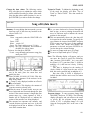
Prepare for recording
4. Press SONG. The SONG LED will light red and the following display will
appear.
5. Press RECORD to get the following display.
Record the first track
6. Press a track select button to select the track you wish to record. With the
default settings, the tracks of the sequencer will transmit on the channel of
the corresponding number, and will be played by the corresponding channel
of the multi you have selected. For example if you have selected Multi
1. POP and wish to record the Pick Bass part, press 1. If you select a channel
for which the multi does not use a voice, there will be no sound.
7. Press PLAY. After a two-measure countdown, recording will begin. Play
along with the metronome to record the part. When you are finished, press
STOP. Press
to return to measure 1.
Record additional tracks
8. As desired, repeat steps 6 and 7 to select and record additional tracks.
Note:
A more complete explanation of using the SY77 sequencer is given in the
following section How to use the sequencer, which explains how to set up your
own Multi, create rhythm patterns, arrange the rhythm patterns in track 16
(the pattern track), record additional tracks, edit the song, and save the
finished song to disk. Refer to page 33.
9
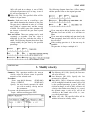
About the SY77: RCM hybrid synthesis
The SY77’s RCM hybrid tone generation system fuses the realism of digital samples with the expressive
power of FM. It uses Advanced Wave Memory 2 (AWM2) and Advanced Frequency Modulation (AFM) in
conjunction with digital filters to allow a wide variety of sound creation techniques.
Advanced Wave Memory
2 (AWM2)
AWM2 uses 16 bit linear sample reproduction with proprietary Yamaha convolution technology (digital filtering) that allows you to emphasize or cut any
desired portion of the frequency spectrum with full realtime control.
Advanced Frequency
Modulation (AFM)
In addition to advancing beyond the FM synthesis capabilities of the DX7 and
previous Yamaha synthesizers, AFM allows you to filter and envelope any
AWM waveform and use the shaped waveform it as part of an FM algorithm to
apply frequency modulation, creating partials that were not present in the
original AWM waveform. This modulated waveform can be processed by additional digital filtering.
Dynamic touch and control
One of the greatest advantages of RCM hybrid tone generation is that it fuses
the realism of digital sampling with the expressive power of FM. Keyboard
dynamics and controllers can be used to control nearly any aspect of the sound,
allowing great musical expressiveness.
The possibilities of RCM
hybrid synthesis
The SY77 allows a wide variety of synthesis techniques to be used, and digital
filtering is always provided for each AFM or AWM element. The following diagrams show how the RCM hybrid synthesis system can simulate many of the
analog and digital synthesizers of the past.
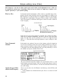
System diagram
Filter style “analog” synthesis: Single cycle AWM waveforms can be
enveloped and filtered to simulate analog synthesizers. (Various sawtooth
and pulse waves are provided, and the SY77’s filters can be configured as
24dB/octave filters with resonance adjustable into oscillation.)
10
Traditional FM: The AFM tone generator can be used alone to produce any
sound that the DX series was capable of, and much more.
AWM sample playback: The AWM tone generator can be used along to
playback high quality digital samples from internal AWM memory or an
optional waveform card.
AWM sample playback mixed with FM: The sounds of the AWM and AFM
tone generators can be layered.
FM modulated by AWM: AWM digital samples can be used to modulate
one or more operators in an FM algorithm, for very complex FM sounds.
AWM sample playback + FM modulated by AWM: In a variation of
the
original sound of the AWM sample can be mixed with the complex AFM
sound.
For techniques which use both AWM and AFM (
) there are two additional possibilities.
l Both AFM and AWM can be used to create sustaining sounds.
l The AFM and AWM tone generators can be used “LA” style, with short
transient AWM waveforms used to create an attack and the AFM tone
generator used to create the sustain component of the sound (or vice versa).
Since each voice can use one two or four AFM or AWM elements, these
synthesis strategies can be combined in complex ways.
11
About the SY77: AFM and AWM voices
The SY77 produces sound using two proprietary Yamaha technologies; Advanced Frequency Modulation
(AFM) synthesis and Advanced Wave Memory (AWM). A special Drum Voice assigns a different AWM
percussion sound to each note of the keyboard.
AFM — Advanced
Frequency Modulation
Frequency Modulation (FM) is a patented Yamaha technology for producing
complex and musical controllable sounds, and was first made famous by the DX7
synthesizer. The SY77’s Advanced FM (AFM) takes FM synthesis to new
levels of realism, expression, and programmability.
Each of the six FM operators in the SY77 can use one of 16 different waveforms, and be connected to each other in 45 basic algorithms (patterns). In addition, each operator has two inputs which can be modulated by feedback from any
other operator, from a noise generator, or from an AWM sample. Compared to
previous FM instruments, many parameters have a wider range of control, and
the SY77 envelope generators have six segments. with looping.
AFM can produce sounds that change dramatically in response to your
playing, allowing a wide range of expressiveness.
AWM — Advanced Wave
Memory
Advanced Wave Memory (AWM) is a patented Yamaha technology for storing
and reproducing digital sound. The SY77 contains 2 Mwords (4 Mbytes) of
AWM samples in Read Only Memory (ROM), including piano, strings, choir,
and percussive sounds among many others. Optional cards can be inserted into
the front panel WAVEFORM slot to make additional sounds available. The sounds
are sampled in 16-bit linear format with a maximum sampling frequency
of 48 kHz.
AWM sounds are high-quality digital recordings of actual instruments.
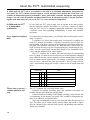
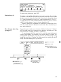
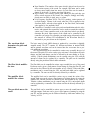
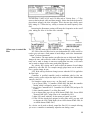
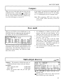
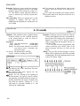
A voice consists of one
two or four Elements
Each sound that you have been playing from the SY77’s keyboard is defined as
a Voice, and consists of one two or four Elements. (The drum voice explained
below is a special case.) Each of these elements is actually the equivalent of an
independent synthesizer; either AFM or AWM.
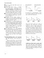
An element can be set to produce sound for only a specific range of the keyboard, or for a specific range of velocities. This allows you to create a voice
which produces different sounds for different ranges of the keyboard, or for loudly
or softly played notes.
Key
Velocity
127
G-8
Element 1:
12
Element 2:
Element 3:
Key
Pitch
Element 4:
The one two or four elements in a voice can produce many types of keyboard
split and layer effects.
On earlier Yamaha synthesizers such as the DX7-II, layers and splits were
created by combining two or more Voices into a “Performance”. This meant that
sometimes you played Voices and other times you played Performances.
However on the SY77, layers and splits can be included in a voice, so you can
simply select a voice and play without considering whether it contains layers or
splits.
Play up to 16 AFM notes
and 16 AWM notes at
once
The SY77 contains two tone generators; an AFM tone generator and an AWM
tone generator. The AFM tone generator can produce up to 16 simultaneous
notes of FM sound, and the AWM tone generator can produce up to 16 simultaneous notes of digitally sampled sound.
Some voices consist of only one element, some of two elements, and others
of four elements. (The Voice mode setting inside each voice determines how
many elements are used.) The important thing to remember is that up to a total
of 16 notes of AFM sound and 16 notes of AWM sound can be sounding at any
time. If a voice plays two or more elements for a single key, the sound will be
more complex and richer, but you will be able to play fewer simultaneous notes.
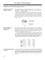
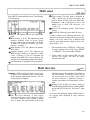
A Drum voice consists of
61 percussive sounds
In addition to the “normal” voices explained above which consist of one two or
four elements, the SY77 provides a special type of voice; the Drum voice.
A drum voice has no elements, but consists of a different AWM sample for each
of the 61 keys of the SY77 keyboard.
A drum voice can be played from the keyboard just like a normal voice.
Usually you will use a sequencer to play a drum voice, providing drums and
percussion accompaniment. Either the SY77’s internal sequencer or an external
MIDI sequencer can be used to play a drum voice.
There is no distinction between normal voice memory and drum voice
memory; either type of voice can be stored in any of the voice memories.
13
About the SY77: filter, pan, and effects
Each of the one two or four elements in a voice has two independent digital filters, and is sent through its
own pan table. The SY77 also has four built-in digital effect processing (DSP) effect units, and effect settings are stored as part of each voice.
Two realtime digital
filters for each element
Each AFM or AWM element in a voice includes two 12 dB/octave realtime
digital filters, each filter independently controlled by its own envelope generator
(EG). One filter is fixed as a Low Pass Filter (LPF) and the other filter can be
used either as a LPF or a High Pass Filter (HPF). This allows you to use the
two in conjunction to create a 12 dB/octave Band Pass Filter (BPF) or a 24
dB/octave LPF. Veterans of analog synthesizers will be happy to hear that the
filter resonance (or “Q”) can be adjusted all the way into filter oscillation.
Since a voice can consist of one two or four elements, a single voice can use
2, 4 or 8 independent filters.
Dynamic pan table for
each element
Each element in a voice is sent through a pan table (64 preset and 32 user pan
tables are provided) that determines how the sound will move between the left
and right outputs. Each pan table has its own EG, and also allows you to select
a pan source (velocity, key note number, or LFO). Another controller can be
used to further bias the panning movement.
Four DSP effects
The stereo output from the voice is sent through the voice output group selector
(both, group 1, group 2, or off) to the DSP effects section. The SY77 contains
two modulation-type effect units and two reverb-type effect units.
Each modulation-type effect unit can produce four different effects; chorus,
flanger, symphonic, or tremolo. Each reverb-type effect unit can produce 40
different effects, including several types of reverb, delay, tone control, distortion,
and various combinations of these. All effect parameters are fully adjustable.
The sound from the two output groups can be sent through these four effect units
in three different routes.
14
AFM x AWM x Filtering =
the SY77
The SY77 can utilize most of the programming techniques of previous synthesizers; FM, sample playback, and realtime filtering. This means that the SY77
can produce the sounds of the classic 24 dB/octave analog synthesizers of the
past, the FM sounds of the DX series, the sampled sounds of many of today’s
instruments ... and also sounds that have never been heard before.
15
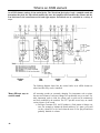
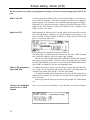
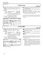
About the SY77: multi-timbral sequencing
In Multi mode, the SY77 acts as 16 synthesizers, each able to be controlled independently and produce its
own sound. The SY77’s built-in 16-track sequencer records and plays back musical data. Each track 1-15
contains an independent musical performance; notes, pitch bends, controller movements, and program
changes. You can create 99 patterns and place them in track 16 (the pattern track). Using the sequencer
together with multi mode lets you use the SY77 to create sixteen-part compositions.
In Multi mode the SY77
is 16 independent
synthesizers
In Voice mode, the SY77 plays a single voice in response to the notes you play
and the controllers (wheels, foot pedals, etc.) you move. However in Multi
mode, the SY77 acts as 16 completely independent synthesizers, each sounding
a different voice and responding independently to notes and controller
movements.
Use a sequencer to play a
multi
To create multi-part compositions, you will play and record one part at a time
using a sequencer.
A sequencer is a device that records music, but instead of recording the
sound of a musical performance, a sequencer records the musical data; the
precise timing of the keys you press, program changes, movements of the sustain pedal, foot controllers, and wheels, etc. When this data is played back, the
result is exactly the same as if you were playing the keys and moving the controllers. You can record Tracks (musical parts played by one instrument) one at
a time, and then playback all the tracks together.
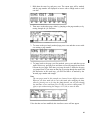
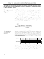
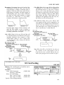
The SY77 sequencer has 16 tracks, and each track plays the corresponding
voice of a Multi. (A multi can also be played by an external sequencer connected
to the MIDI IN terminal, and the sequencer can also transmit data from MIDI
OUT to control external synthesizers.) For example, you might select a piano
voice for voice 1 and record the piano part on track 1, select a strings voice for
voice 2 and record the strings part on track 2, and so on for all sixteen tracks and
voices.
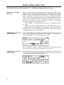
SEQUENCER
Measure
1
MULTI
2
3
Each timbre in the multi can play a different voice
Track 1
Piano
Track 2
Strings
Track 3
Brass
...
Track 16
Three ways to record —
realtime, punch-in, and
step
16
Percussion
The SY77 sequencer lets you record in three ways.
Realtime: In realtime recording, notes and controller movements are
recorded with the exact timing that you play them.
Punch-in: Punch-in recording is like realtime recording, except that the data
is recorded only for the measures you specify. This is useful for fixing minor mistakes in an otherwise well-recorded track.
Step: Step recording allows you to enter notes and other data one step at a
time. This allows you to record complex musical phrases that would be impossible for a human to play, and also can be used to edit individual notes that have
already been recorded.
Sequence editing jobs
A wide variety of “sequence editing jobs” are provided to allow you to modify
the musical data that has been recorded.
l Tracks can be moved forward or backward in time, mixed, or deleted.
l Measures can be copied, erased, deleted, or created.
l For specified measures you can quantize the data (adjust each note to a
specified timing precision), transpose it to a different pitch, adjusted the
velocity (playing strength), or modify the gate time (note length).
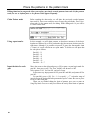
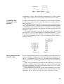
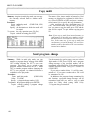
99 Patterns can be used in
a song
Track 16 is a dedicated Pattern track. In pattern mode, you can create up to 99
patterns; short phrases one to thirty-two measures long. Patterns are especially
suitable for rhythm parts; since the same basic drum pattern may be repeated
many times during a song, you can record a single pattern and place it in the
pattern track wherever you want it to play back. When song playback reaches
that point, the pattern will play back along with track 1-15.
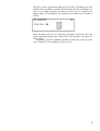
Track 16 contains
pattern numbers
Ptn
01
Ptn
02
Ptn
01
Playback result
(Ptn. 01 =
Pattern recording —
realtime or step
Ptn. 02 =
Patterns can be created either by realtime recording or step recording.
Realtime recording: Since patterns are sometimes used for drum and
percussion parts, realtime pattern recording has features that make it easy for
you to build up complex drum parts. There is no need to play all the rhythm
instruments at once. When you record a pattern in realtime, the pattern will continue repeating, and you can add each instrument one by one as the pattern
repeats.
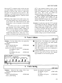
Step recording: When step recording a pattern, the LCD will graphically
indicate exactly where you are in the pattern. You can move back and forth,
entering notes on any beat to build up a pattern of any complexity.
17
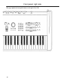
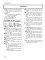
Front panel: left side
In order to understand the rest of this manual and take full advantage of the SY77, you will need to know
the names and uses of the controls and other features of the front panel. This page explains the left side of
the front panel, including the LCD.
Keyboard:
The 61-note keyboard of the SY77 is sensitive to
key-on velocity and to channel aftertouch.
Pitch and modulation wheels:
The PITCH wheel bends the pitch up or down, and
is spring-loaded to return to center position. The
MODULATION 1 wheel affects the sound as
specified by the voice parameters; usually controlling the amount of vibrato or tremolo. The
MODULATION 2 wheel also affects the sound as
specified by the voice parameters, but is centerdetented to help you return it to exactly center
position.
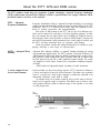
Disk drive:
The 3.5" 2DD floppy disk drive can economically
store large amounts of the various types of data
used by the SY77. The disk drive indicator LED
will light when the disk is being read or written.
Never attempt to remove the disk while this
LED is lit. Doing so could damage the disk.
Insert the disk with the label facing up, from
the end with the metal shutter. To remove the
disk, press the button at the lower right of the
drive.
DATA card slot:
An optional RAM card (MCD64) can be inserted
into the DATA slot to store data for the SY77’s
tone generator.
Waveform card slot:
An optional waveform ROM card can be inserted
into the WAVEFORM slot to provide additional
AWM sounds.
Volume sliders:
These sliders regulate the output volume from
the two pairs of stereo output on the rear panel.
Liquid Crystal Display (LCD):
The 240 x 64 pixel LCD is backlit for readability
even in dark locations. Adjust the CONTRAST
control on the rear panel to suit your viewing
angle.
18
Mode select keys:
The functions of the SY77 are divided into five
modes. Press one of these buttons to select the
mode, and the LED above the button will light
red to indicate the selected mode.
The SY77’s Synthesizer is always in one of
two modes; Voice mode or Multi mode. One of
the LEDs above these two keys will always be
lit (green, if neither Voice nor Multi mode is
selected) to indicate which mode the synthesizer
is in.
The SY77’s Sequencer is always in one of
two modes; Song mode or Pattern mode. One of
the LEDs above these two keys will always be
lit (green, if neither Song nor Pattern mode is
selected) to indicate which mode the sequencer
is in.
The Utility mode LED is either red (when
Utility mode is selected) or off (when a different
mode is selected).
Edit/Compare:
Press this button to edit the data of the currently
selected; Voice, Multi, Sequencer Song, or
Sequencer Pattern. In voice edit or multi edit
mode, pressing this button allows you to compare the original data with the edited data.
Copy:
While editing, this button is used to copy various
types of data.
Effect Bypass:
At any time, pressing this button will allow you
to hear the sound without the DSP effects. The
red LED will light to indicate that the effects are
bypassed. To defeat effect bypass, press the
button again.
Sequencer control:
The SY77 sequencer can be used at any time,
even while editing. The data played or recorded
will depend on whether the sequencer is in Song
or Pattern mode.
LOCATE
RECORD
STOP
RUN
: Move to the beginning of the song
: Move back one measure (press and
hold to rewind)
: Move to a previously specified
location
: Move forward one measure (press
and hold to fast forward)
: Start recording (during recording,
LED lights red)
: Stop playback or recording
: Begin playback (blinks green on each
beat of the click, and blinks red to
indicate the first beat of the
measure)
Shift:
While the SHIFT button is held down, the function
keys F1-F8 will act as F9-F16. Also, pressing
the JUMP key while SHIFT is held down will mark
the current location.
Function keys:
In some jobs, the bottom line of the LCD will
display a function for F1-F8 (F9-F16 while the
Shift key is held down). These keys are used in
various ways, such as selecting menu items
shown in the function key display, moving the
cursor in the display, or executing a function
shown in the function key display.
Exit:
This key moves back to where you last were
before entering the level you are now in; i.e., it
moves back to the previous branch of the function
tree.
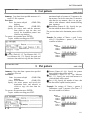
19
Front panel: right side
This page explains the front panel features to the right of the LCD.
20
Page
These keys move to the next or previous function
within the same level; i.e., they move from branch
to branch of the tree of functions.
Jump/Mark:
The LCD of each function in the SY77 has a
“system page number”, which is displayed at
the upper right of each LCD. If you know the
number of the page to which you want to jump;
press JUMP, use the numeric key pad to enter the
page number, press ENTER, and you will be
taken to the specified page.
If you press MARK while holding SHIFT, the
current page will be marked. Later when you are
in another page and wish to return to the marked
page, press JUMP and then ENTER, and you will
be taken to the previously marked page. (The
page you jumped from will now be marked.)
Data entry slider, Data entry wheel, -1/+1:
The data entry slider, data entry wheel, and
-1/+1 keys are all used to modify the data value
indicated by the cursor.
When you move the DATA ENTRY slider, the
data is directly set to the value indicated by the
slider position; i.e., use the data entry slider to
“absolutely” specify the data.
The data entry wheel can be rotated freely in
either direction, and will change the current data
value continuously. In job or voice directories it
will also move the cursor around the screen.
The -1/+1 buttons will decrease/increase the
current data value in steps of one. (These buttons also act as “yes/no” or “on/off” for various
functions.)
The data entry wheel and -1/+1 buttons can
also be used to select programs (voice or multi).
The slider, wheel, and -1/+1 will not necessarily act in the same way for all functions.
Exceptions will be noted when each function is
explained.
Cursor keys:
Use these keys to move the cursor in the LCD to
select items or data. (Simply moving the cursor
will not modify the data.)
to select a voice or multi
l after pressing JUMP to specify the page to
which you want to jump
l to directly enter a value for the data indicated
by the cursor
l to directly select an item from a directory
When step recording sequencer data, the numeric
key pad is used to enter the note values printed
above each key. When specifying a voice name
etc., the numeric key pad enters the characters
printed below each key.
In general to enter a value, use keys 0-9 to
specify the value, press +/- to change the sign if
necessary, and press ENTER. In some cases,
ENTER is not necessary.
l
Memory source select:
When selecting a memory, press one of these
buttons to select the source; INTERNAL (internal
user memory), CARD (card memory), and PRESET
1 or 2 (internal ROM preset data). The LED
above each button will light to indicate the
selected memory.
When in Voice Edit mode, these buttons are
also used to directly select elements 1-4.
Bank select:
When selecting a Voice program, press one of
these buttons to select the bank; A-D. The LED
above each button will light to indicate the
selected bank.
When in Voice Edit mode, these buttons are
also used to turn elements 1-4 on/off.
Program select:
These keys are normally used to select programs
(voice or multi). The selected button will light
red. In addition, they have the following special
uses.
Voice edit mode: While you are editing an
AFM element, buttons 1-6 select operators 1-6,
and buttons 9-14 turn operators 1,6 on/off.
Sequencer mode: Buttons 1-16 will
mute/unmute tracks 1-16. The LEDs will light
green to indicate tracks which contain data.
Muted tracks which contain data will blink green
during playback. Tracks selected for recording or
editing will light red.
Numeric key pad:
Use these keys to enter data as an absolute
number.
21
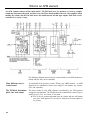
Rear panel
In order to connect the SY77 to other devices (an amp/speaker system, MIDI equipment, footswitches,
etc.), you will need to know the names and uses of the various items on the rear panel.
MIDI IN, OUT, THRU:
Any MIDI device (sequencer, keyboard, WX7/11 wind controller, G10 guitar
controller, etc.) can be connected to MIDI IN to play the sounds of the SY77.
Data produced by the SY77 keyboard and the SY77 internal sequencer is
transmitted from MIDI OUT. By connecting a tone generator module or synthesizer to this terminal, you can play it from the SY77 keyboard.
The data received at MIDI IN is re-transmitted unchanged from MIDI
THRU. Another MIDI device connected to this terminal will receive the same
MIDI data that the SY77 receives.
Contrast:
This knob adjusts the contrast of the LCD. Adjust it to suit your viewing angle.
(At extreme settings the display will not be readable.)
Breath:
By connecting an optional BC1 or BC2 breath controller to this jack, you can
expressively control various aspects of a sound by blowing into the breath controller. For example, a voice might be programmed so that the tone or volume
changes in response to breath controller signals. (The effect will depend on the
breath control sensitivity parameter settings of each voice.)
Click volume:
This knob adjusts the volume of the click (metronome) produced by the
sequencer.
Foot volume:
An optional foot controller (FC7, FC9, etc.) can be connected here to regulate
the overall volume of the SY77.
Foot controller:
An optional foot controller (FC7, FC9, etc.) can be connected here to perform the
function (foot controller, portamento time, etc.) determined by the Assignable
Foot Switch setting of Utility mode.
22
Sustain:
An optional foot switch (FC4, FC5) can be connected here to act as a sustain
pedal.
Foot switch:
An optional foot switch (FC4, FC5, etc.) can be connected here to perform the
function (hold on/off, portamento on/off, etc.) determined by the Assignable Foot
Switch setting of Utility mode.
Phones:
A pair of stereo headphones can be connected here to hear the combined stereo
sounds of outputs 1 and 2.
Output 1/1+2 (L/MONO, R):
If the OUTPUT 2 L/R jacks are not plugged in, these jacks will output the combined stereo signal from group 1 and group 2 of the DSP effects unit. If the
OUTPUT 2 L/R jacks are plugged in, these jacks will output the sound from the
group 1 stereo output of the DSP effects unit.
If only the L/MONO jack is used, it will carry the combined output of L and R.
(Use the L/MONO jack if your mixer/amp system has only one input.)
Output 2 (L, R):
These jacks output the sound from the group 2 stereo output of the DSP effects
unit. If your mixer/amp system has four or more inputs, using both the OUTPUT 1
and the OUTPUT 2 jacks will allow you to treat the two output groups in different
ways, perhaps by panning them to different locations, or processing them
through different external effect devices.
Power switch:
The power is on when this switch is pressed. The front panel display will light
when the power is turned on.
Power cable:
Plug the power cable into an AC outlet of the correct voltage.
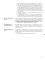
23
How to move around: job directories
The functions of the SY77 are organized into five main Modes and four editing modes. Some modes have a
Job Directory that shows the various Jobs (functions) in the mode. Move to the desired function by selecting a job from the job directory.
Five main modes (1)
Play modes and Edit
modes (2)
The SY77 operates in five main modes. Press one of the five mode select buttons to enter the corresponding mode. (A red LED will light to indicate the
selected mode.)
Press
to enter
where you can
VOICE
MULTI
SONG
PATTERN
UTILITY
Voice mode
Multi mode
Song mode
Pattern mode
Utility mode
Select and play a Voice.
Select and play a Multi.
Playback the song in sequencer memory.
Select and playback a pattern from sequencer memory.
Make overall settings for the SY77, manage disk and card
data, etc.
While in voice, multi, song, or pattern mode, press EDIT to move to the corresponding edit mode. For example Voice Edit mode is where you modify the settings that make up a voice, and Song Edit mode is where you modify the data
that makes up a song. (There is no “utility edit” mode.)
Press
to enter
then press
to enter
VOICE
MULTI
SONG
PATTERN
Voice mode
Multi mode
Song mode
Pattern mode
EDIT
EDIT
EDIT
EDIT
Voice Edit mode
Multi Edit mode
Song Edit mode
Pattern Edit mode
To leave an edit mode, simply re-select any of the five main modes (or press
EXIT from the top level of the edit mode to return to the main mode from which
you came).
Select a job from the job
directory (3)
Whenever a mode or function is sub-divided into more than one job, there will be
a “job directory” that lists the various items or operations. For example, when
you enter Multi Edit mode, the following display will appear.
This lists the various parameters that can be adjusted in Multi Edit mode;
1.Voice, 2.Volume, 3.Tuning, etc.
To select an item from a job directory, use the arrow keys to move the
cursor to the desired item and press ENTER. For example, if from the above
display you press once to move the cursor to “2.Volume” and press ENTER,
the following display will appear.
24
To return to the job directory, press EXIT.
Function keys (4)
Sometimes a job will be divided into two or more screens. For example,
“2.Volume” is divided into two jobs; one to set the volume for voices 1-8 and
the other to set the volume for voices 9-16. Notice that the bottom line shows
“1-8” (above function key F1) and “9-16” (above function key F2). The “1-8”
is displayed in inverse video to indicate that the volumes of voices 1-8 can be
edited. To edit the volumes of voices 9-16, press function key F2.
Whenever function key assignments are displayed in the bottom line of the
LCD, the current selection is indicated in reverse video. Press a function key to
move to the desired job.
Move between jobs using
(page) (5)
Suppose that you wanted to move from the “2.Volume” job to the “3.Tuning”
job. You could press EXIT to return to the job directory, and then press 3 and
ENTER to move to “3.Tuning”, but there is a faster way.
To move between jobs of the same level (i.e., inside the same job directory),
use the PAGE
keys. For example if you are now in the “2.Volume” job,
pressing PAGE would take you to the “1.Voice” job, and pressing P A G E
would take you to the “3.Tuning” job. When moving to a nearby job, this is
usually faster than returning to the job directory.
Select a main mode
Enter edit mode
Use the cursor or
numeric keypad to select
a page, and press ENTER.
PAGE to
Use
move between pages
of the same level.
Use the function keys
to move within
multi-screen pages.
25
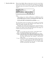
How to move around: the jump function
If you already know the exact function you need to use, it is possible to Jump directly to a specific page
number instead of working your way through the job directories. The jump function also allows you to
repeatedly jump back and forth between two jobs.
Jump to a specified page
If you need to move to a distant job, it may sometimes be necessary to press
EXIT several times, and then move down through two or more job directories. In
such cases, it is much faster to jump directly to a specific page.
You may have noticed that most page displays have a unique three-digit
number in the upper right corner. This is the Display Page number. For example,
“Multi edit 2. Multi Volume” is page #402. If you frequently need to adjust the
settings of this page, remember this page number. Then, no matter where you
are, you can press JUMP, 4, 0, 2, and ENTER to jump instantly to that page.
1. Press
JUMP.
2. Enter the three digit page number.
3. Press
ENTER
and you will jump to the specified page.
While you are becoming familiar with the SY77 it will probably be easier for you
to select the desired page while viewing a page directory. However as you gain
more experience, you may find it convenient to use the JUMP key to go directly
to frequently-used pages.
Jump between two
marked pages
26
It often happens that you will need to repeatedly make adjustments in two
different pages, which may be widely separated. The jump/mark function allows
you to jump back and forth between two pages.
Suppose you are in song edit job directory, and need to adjust the volume
levels of the voices in the multi.
1. Hold down the SHIFT key and press JUMP. The current page will be marked,
and the page number will displayed in inverse with a triangle mark to indicate this.
2. Then move to the other page, either by jumping to the page number, or by
moving through the job directories.
3. To return to the previously marked page press JUMP and then ENTER without entering a page number.
4. To jump back to the page you first marked, press JUMP and then ENTER
again. In this way, pressing JUMP and then ENTER will jump back and forth
between the two pages. Each time you jump, the mark is shifted to the page
you jumped from. If you return to that page by moving through the modes and
job directories in the usual way, you will find that it is marked by the
inverted page number and triangle.
Note:
The two pages used in this example are located in two different modes.
Whenever you leave multi edit (or voice edit) mode after modifying the data,
either by pressing EXIT or by using the Jump function, you will pass through
the Auto-Store screen, and must press F6 (Ret) to return to editing mode, F7
(Quit) to quit without storing the changes, or F8 (Go) to store the data.
If the data has not been modified, this Auto-Store screen will not appear.
27
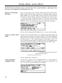
How to enter data
To select a voice, adjust a parameter, or give a name to a newly created setting, you will need to enter
various types of data into the SY77. The -1/+1 keys, data entry slider, and data entry dial provide various
ways to enter data. Use the data entry method that is most appropriate for each situation. (The following
page explains how to use the numeric key pad.)
Select the data to enter
First, use the arrow keys
want to modify.
to move the inverse cursor to the data you
Move the cursor
LCD
Next you will modify the value using one of the following; -1/+1 keys, data entry
wheel, data entry slider, or the numeric key pad. The method you use will
depend on how you want to modify the data.
-1/+1 (no/yes)
If you want to decrease or increase the existing data value one step at a time,
use the -1/+1 keys. Each time you press the -1 or +1 key, the data will decrease
or increase one step. This method allows you to move in precise steps, but can
take a long time when you need to make a major change in the value.
Some parameters consist of a “off/on” setting, and sometimes you will be
asked to reply “no/yes” to a question (such as “do you really want to do
this?“). In such cases, press -1 to turn something off or to answer “no”, and
press +1 to turn something on or to answer “yes”.
Decrease/increase
the data one step
at a time
28
Data entry wheel
If you want to decrease or increase the existing data value by a significant
amount, use the data entry wheel. As you rotate the wheel to the right
(clockwise) the data will increase, and as you rotate the wheel to the left
(counter-clockwise) the data will decrease. The wheel rotates freely; it modifies
the data by its movement, not by its position. Like the -1/+1 keys, the data
entry wheel modifies the existing value, but is more suitable for making larger
continuous changes. In job or voice directories, the wheel can be used to select
jobs and voices.
Data entry slider
If you want to set a data value to some setting relative to the entire range of
that value (for example “maximum”, “minimum”, or “about 90% of maximum”),
use the data entry slider. When you move the slider, the data value is immediately changed to correspond to the position of the slider. The range of the
slider will match the range of the parameter value. For example if the parameter
being modified has a value range of 0-127, pulling the slider fully towards you
will set a value of 0, and pushing the slider fully away from you will set a value
of 127. Setting the slider exactly in the middle of its range would set a value of
64.
Since the range of the slider always matches the range of the parameter you
are adjusting, there is no need to remember the range of the parameter; just
move the slider to the position that corresponds to the relative setting you want.
DATA ENTRY
(range of each parameter)
0-99 0-7 -50 – +50
+50
99
7
50
3
+0
0
0
–50
29
How to use the numeric key pad
The numeric key pad can be used to enter an absolute data value, and also to enter characters for a
memory name or disk file name.
How to enter absolute
numerical data
If you want to set a data value to some specific number (for example “57” or
“121”), use the numeric key pad. Press one or more keys 0-9 to specify the
number, press the – key to change the sign if necessary (when entering a negative number), and press ENTER. For example if you wanted to enter the number
“–18”, you would press 1, 8, –, ENTER. If the data value has a three-place range
(such as 0-127), there is no need to add a zero in front.
In most displays, the first digit you enter from the numeric key pad will be displayed blinking with an asterisk after it. When. you enter the second digit the
number will be finalized.
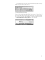
How to enter character
data
30
You will sometimes need to enter character data to specify a voice name, multi
name, file name, etc. When the currently selected parameter requires that you
enter character data, the numeric key pad will act in a different way than usual.
To try this out, jump to the Voice Name page by pressing the following keys in
order; JUMP, 2 ,2, 9, ENTER. The following display will appear.
This display is essentially the same as for any other job that requires you to
enter character data. Press F1 (Clr) to clear the currently set name, and press F2
(Uppr) or F3 (Lowr) to select uppercase or lowercase letters.
Notice that below the 0 key are printed the characters “A”, “B”, and “C”.
Press the 0 key, and the numeral “0” will appear. Press it again for the
character “A”, again for “B”, and again for “C”. Press it once more and “0”
will reappear. In this way, each time you press a key, the character indicated by
the cursor will alternate through the alphabetical characters printed below it and
the numeral printed on the key itself. (If you press another of the numeric keys,
the cycle will begin from the first character.) Notice that the third press of 8 is an
apostrophe, that 9 gives you an asterisk, ampersand, and an underline character,
and that - enters a hyphen, slash, comma, and period.
Other characters are available in addition to the characters entered using
the numeric key pad. These characters can be selected using the DATA ENTRY
slider or the –1 +1 keys. Moving the DATA ENTRY slider will scroll through all
available characters in the following order.
(Space) ! ” # $ % & ’ ( ) * + , - . / 0~9 : ;
< = > ? @ A~Z [ \ ] ^ _ ` a~z { | } ~ (Space.)
Use the
keys to move the cursor, and enter characters for the desired name.
Pressing the ENTER (space) key will enter a blank and move the cursor to the
right.
Other uses of the numeric
key pad
In step recording mode, the numeric keys specify the note value printed above
each key. For example key 1 will enter a whole note and key 6 will enter a 32nd
note. Details will be explained in the section on step recording.
In jobs where you are required to set parameters and execute, you will
execute the specified job by pressing the ENTER button. Details will be
explained when necessary.
31
32
HOW TO USE THE SEQUENCER
This section is a step by step explanation of how to create a song using the SY77’s built-in
sequencer. By using the sequencer in conjunction with Multi mode, you can create songs of
up to 16 independent parts.
Contents of this section
How the sequencer controls the tone generator
Set up a multi
Create rhythm patterns
Place the patterns in the pattern track
Realtime recording
Punch-in recording
Song editing
Using a song edit job
Saving your sequence to disk
page
34
36
38
40
42
44
46
48
50
33
How the sequencer controls the tone generator
Although the SY77’s tone generator and sequencer are contained in the same unit, these two are independent. When the tone generator is in Multi mode, each channel of the multi can be played by a different track
of musical data from the sequencer.
The tone generator and
sequencer are
independent
The SY77 can be divided into two sections; the tone generator that produce
sound, and the sequencer that records and plays back data such as notes and
controller movements to control sound. The sequencer is completely independent
of the tone generator, and has its own set of control buttons. This allows you to
start or stop, record or playback at any time even while editing a voice or multi.
It is especially helpful to edit a voice while it is being played by a sequencer
pattern, or to make adjustments to the volume balances or pan settings of a
multi while listening to the song playback.
The sequencer will record data from the SY77’s keyboard and also from
MIDI IN, and will playback data to the SY77’s tone generator and also transmit
it from MIDI OUT. The tone generator will produce sound in response to data
from the sequencer and also from MIDI IN.
How the sequencer
controls the tone
generator
Depending on whether the SONG or the PATTERN button was last pressed, the
sequencer will record and playback data either in Song mode or in Pattern mode.
Depending on whether the VOICE or the MULTI button was last pressed, the tone
generator will produce sound either in Voice mode or in Multi mode. This means
that the sequencer and tone generator can work together in four possible ways
as shown in the following table.
Sequencer
Mode
Transmits
Tone generator
Mode
Receives
SONG
SONG
PATTERN
PATTERN
16 channels
16 channels
1 channel
1 channel
VOICE
MULTI
VOICE
MULTI
1 channel
16 channels
1 channel
16 channels
As you can see from the above table, the greatest musical complexity is possible when the sequencer is used in Song mode to play the tone generator in
Multi mode. However other combinations of sequencer and tone generator will
be useful when creating sequences, patterns, or voices, For example it is often
helpful to keep a sequencer Pattern playing while you edit a Drum Voice.
34
Fifteen tracks + pattern
track + patterns = one
song
Each track 1-15 contains an independent musical performance; notes, pitch
bends, controller movement, and program changes. Track 16 is a dedicated
Pattern track. It contains pattern numbers and repeat marks. When playback
comes to a pattern number, the specified pattern will be played.
About this tutorial
In the following pages of this section, we will be explaining the entire process of
creating a song; creating patterns and arranging them in the pattern track,
recording other tracks, and editing. Finally we will save the completed song to
disk. Our procedure will be as follows.
1. Create a Multi by selecting a voice for each of the 16 channels, and making
settings for volume, pan, etc. for each channel.
2. Enter Pattern mode and create several rhythm patterns.
3. Enter Song mode and place these patterns in track 16 (the pattern track).
4. Record one or more tracks in realtime.
5. Punch-in on a section of the track to fix a mistake.
6 . Use song edit mode to correct and insert individual data events.
7 . Use a song edit job to transpose specified measures.
8 . Save the completed sequence to disk.
Note:
The output channel of the sequencer tracks can be changed if desired, allowing you to use two or more tracks to control a single channel of the multi.
However to keep this tutorial simple, we will select normal voices (piano,
bass, strings, etc.) for channels 1-15 of the multi and a drum voice for channel
16 of the multi. Tracks 1-15 of the sequencer will contain the music for the
normal voices, and track 16 will contain the patterns to play the drum voice.
35
Set up a multi
When the SY77’s tone generator is used in Multi mode, it will function as 16 independent synthesizers. This
allows each track of the sequencer to play a different sound.
Start with the initial multi
Since in this tutorial we will be creating a song with more than one track, we will
use the SY77’s tone generator in multi mode so that it will function as 16 independent synthesizers.
Press MULTI, then press EDIT. While holding SHIFT press F7 (15) to select
the Initialize job.
Press +1/YES. The display will show “Completed!”. Press EXIT to return to the
Multi Edit job directory.
Select the voice for each
channel of the multi
Press
F1
(01) to get the following display (or JUMP #401).
Specify the voice that will be played by each channel 1-16 of the multi by moving
the cursor and using the MEMORY, BANK, and the memory select buttons 1-16.
It is not possible for an Internal multi to use Card voices, nor is it possible for a
Card multi to use Internal voices.
In this example we will be assuming that you have selected the following
voices for channels 1-3 and 16. Select voices as desired for the other channels
of the multi.
Multi ch. no.
Voice no.
Voice name
2
P1-A10
Wood Bass
3
P1-A11
ChamberStr
P2-D15
Drum 1
...
16
Press
36
EXIT
to return to the Multi Edit job directory.
Make effect settings for
the multi
Press F7 (07) to select 07:Effect from the Multi Edit job directory and then press
F1 to select 01:Effect Mode Select (or JUMP to page #413). With the initial settings the effect mode will be off. Press +1/YES to select effect mode 1.
Press PAGE three times to get the Reverb Effect 1 set display. With the initial
settings the Reverb Effect 1 will be 00:Through. Press +1/YES to select
01:Rev.Hall.
Press
EXIT
twice to return to the Multi Edit job directory.
Other settings in multi edit
mode
To keep this example simple, we will leave the rest of the multi settings at their
initial values. After completing this tutorial, you can read about Multi edit in the
Reference section to learn more about a multi.
Save the newly created
multi
From the Multi Edit job directory press EXIT. Since you have modified the data,
the top line of the display will blink “Auto-store multi”.
Press F8 (Go) and the multi will be stored into the currently selected multi
memory. Or, if you want to keep the previous data of that multi, use the memory
select buttons 1-16 to specify a different memory before you press F8 (Go).
The bottom line of the display will ask “Are you sure?‘. Press +1/YES and
the newly edited multi will be stored, and you will return to multi play mode.
37
Create rhythm patterns
Pattern mode allows you to create short phrases of 1-32 measures. These patterns can later be placed in
track 16 (the pattern track) of song mode for use as rhythm parts or for phrases which appear frequently.
Make settings for pattern
recording
Press PATTERN, then press RECORD to make the RECORD LED light. Make the
following settings.
PATTERN01
(we will record pattern 01)
Time
= 4/4
(the pattern will be in 4/4 time)
Length
= 01
(the pattern will be one measure long)
(notes will be corrected to the nearest 1/16th
Quantize = 1/16
Receive Ch = kbd
(notes will be recorded from the SY77 keyboard)
Click
= rec
(the click will sound only while recording)
Click Beat = 1/4
(the click will sound on each quarter note)
Sync
= internal (the SY77 will keep time to its own internal clock)
Press
F1
(Real) to select realtime recording. The LCD should now be as follows.
Record the pattern
When you enter pattern recording mode, the keyboard will transmit the channel
selected for track 16 (the pattern track) of the sequencer. With the default settings this will be channel 16, which will play the Drum 1 voice we selected for
channel 16 of the multi.
Before you begin recording, play the keyboard to locate the rhythm sounds
you will be using. Our first pattern will be a simple rhythm backing of bass drum,
snare, and hi-hat.
Press RUN and pattern recording will begin. Keep time to the click and play
the bass drum part (the C1 key) for one measure. The pattern will continue to
repeat from beginning to end, and you can hear the bass drum pattern just
recorded. Next play the snare notes (C#2), and finally play the hi-hat notes (A2
and B2). Of course it is possible to record more than one note at a time, and as
you become more skilled you may wish to do so. You can delete any given note
from the pattern by pressing SHIFT while holding down the key of the unwanted
note, and allowing the pattern to run through the section you wish to erase.
Press STOP and pattern recording will end. Notice that the upper right of the
LCD now shows PATTERN01w. The “w” indicates that data has been written
into the pattern.
Record another pattern
For the second pattern we will record a fill-in with toms (E1, F1, F#1, G1) and
crash cymbal (C3). Press RECORD to make the RECORD LED light, and move the
cursor to the upper right and select PATTERN02. Notice that there is no “w”
after the pattern number, since no data has been written into this pattern.
Press RUN and pattern recording will begin. Now you can record an
appropriate fill-in pattern.
Press STOP and pattern recording will end.
38
39
Place the patterns in the pattern track
Editing functions in song mode allow you to place previously created patterns into track 16 (the pattern
track) for use as rhythm parts or for phrases which appear frequently.
Chain Pattern mode
Before recording the other tracks, we will place the previously recorded patterns
into track 16. Press SONG and then EDIT to enter song edit mode. Press 16 to
select track 16 (the pattern track) for editing. While editing track 16 you will be
in Chain Pattern mode.
Using repeat marks
In this example, we will chain patterns so that three measures of the basic
rhythm are followed by a fill-in, and make this four-measure chain repeat for
eight times. Although is is possible to input all 32 parts (the four-measure chain
× 8 times), it is more efficient to use repeat marks. To do this we will input data
for each part as follows.
Part
Part
Part
Part
Part
Part
Input the data for each
part
40
001
002
003
004
005
006
: II:
: 01
: 01
: 01
: 02
: :II × 7
Move the cursor to the right and press F2 (II:) to enter a repeat begin mark for
part 001, then press ENTER. The “Part” display will advance to 002.
Select pattern “01w” for Part 002, and press ENTER.
In the same way input pattern 01 for parts 003 and 004, and pattern 02 for
part 005.
For part 006, press F3 (:II). Use –1 +1 to specify “ × 7” so that the range of
parts between the begin and end repeat marks repeat 7 times. Be sure to press
ENTER to enter each part.
When you are finished editing the chain of patterns, press EXIT to return to
Song Play mode. Press RUN and you will hear the newly edited chain of patterns.
41
Realtime recording
In realtime recording the notes you play will be recorded in the exact timing with which you play them.
Make settings for
realtime recording
From the song play display press RECORD to enter song record mode and press
F1 (Real) to select realtime recording.
If you have been following along with the previous pages of this section, the
various settings will be the same as you specified in Pattern recording. However
for realtime recording a track, you may wish to turn off quantization. Move the
cursor to Quantize and press –1 several times to select “off”.
Record the first track
In song mode, the memory buttons 1-15 select the track to record. For this
example, press the select button 1 to make the track 1 LED light red. With the
default settings track 1 of the sequencer will transmit its data on channel 1.
Since in this example you have selected a piano voice for channel 1 of the multi,
you will hear the piano voice when you play the keyboard.
To begin recording press RUN. The RUN LED will light red, and after a twomeasure countdown recording will begin. Play the keyboard. As you record, the
Measure display will advance to show the number of the measure currently
being recorded.
When you are finished recording the track, press STOP. You will return to
the song play display.
Press to return to measure 1, and press RUN to hear the track you just
recorded. Press STOP to stop playback.
Record additional tracks
To record additional tracks,
l press to return to measure 1
l press RECORD
l press a memory button 2-15 to select another track (LED lights red)
l and press RUN to record the track while listening to previously recorded
parts. Press STOP to stop playback.
42
In this way, record all the tracks of the song. As you record each track you will
hear the previously recorded tracks playback. The multi we created in the
beginning of this example uses the following voices.
Multi ch. no.
Voice no.
Voice name
1
P1-A01
GrandPiano
2
P1-A10
Wood Bass
3
P1-A11
ChamberStr
P2-D15
Drum 1
...
16
With the initial settings of the sequencer, tracks 1-16 will transmit their data on
channels 1-16 (this can be changed) and be received by channels 1-16 (this
cannot be changed) of the multi. If you are following this example, record the
piano on track 1, bass on track 2, and strings on track 3.
43
Punch-in recording
In punch-in recording the notes you play will be recorded in the exact timing with with you play them, but
only over the measures you specify. This is useful when you wish to re-record only a specific section of a
previously recorded track.
When to use punch-in
recording
Suppose that while recording track 2, you made a few mistakes in measures 15
and 16. While it is possible. to re-record the entire track, it is more efficient to
use punch-m recording to re-record only the measures necessary. There is no
purpose in using punch-m recording on a track which contains no data.
Punch-in recording allows you to specify the measure at which recording will
begin and the measure at which recording will end. Measures before and after
this area will not be affected.
The following diagram shows the result of punch-in recording.
Specify the area of
measures to re-record
In this example we will assume that you wish to re-record measures 15 and 16
of track 2.
1. Press SONG to enter song play mode.
2. Press RECORD to enter song record mode.
3. Press F3 (Pnch) to select punch-in recording.
4. Press the memory select button 2 to select track 2 for recording.
5. Specify “From Meas =015” and “To Meas =016”.
Re-record the specified
measures
Move the cursor to Measure and select a point a few measures before 015. This
will give you a chance to get the feel of the section you are going to re-record.
To begin recording press RUN. The RUN LED will blink on the beats. Play
along with the original. When measure 15 is reached, the original recording on
track 2 will disappear and your new playing will be recorded. When measure 16
ends, the original recording of track 2 will reappear, but playback will continue.
Press STOP and you will return to the song play display.
44
45
Song editing
Song edit mode allows you to modify, insert, or delete individual events that have been recorded in tracks
1-15.
When to use song edit
As explained earlier, a sequencer records not the sound of a musical performance but the musical data. Notes, controller movements, program changes, and
other data are recorded as individual events. Song edit mode allows you to edit
individual events that have been recorded in tracks 1-15.
In this example we will assume that the piano part in track 1 was perfect
except for one F3 in the tenth measure that should have been an F#3.
Use Data Change mode to
modify the data
From the song play mode or song record mode display, press EDIT. Press a
memory select button 1-15 to select the track to edit (track 1 in this example).
If you are in Data Insert or Graph modes as explained below, press F8
(Data) and then press F2 (Chng) to select data change mode. The following
display will appear.
In this mode you can view and edit data in numerical form. With the cursor
located at the measure number, use the dial or the –1 +1 keys to move through
the data in the track. The lower part of the display will show the location
(measure, beat, clock) and parameters of each data event.
When you find the data you wish to modify (in this example, the mistaken
note F3), move the cursor to Note and press +1 to change the F3 to F#3. Press
ENTER to finalize the change.
Use Data Insert mode to
insert new data
46
Song edit also allows you to insert new data into the track. In this example we
will insert a program change at the beginning of measure 17 to change the voice
played by this track. Press F1 (Ins) to select data insert mode.
To specify the type of data to be inserted, press and hold SHIFT. Then press F2
(Prog) to insert a program change.
With the cursor at the far left, specify measure 17 as the location where the
program change will be inserted. Next, move the cursor to the right and specify
the Data (program change number 000...127). For this example, specify a
program change of 3 to select P1-A03 DynoE.Pno.
Press ENTER to insert the program change data. In the same way, insert another
program change number 1 at the beginning of the track (measure 001-01-00/96)
so that the original voice P1-A01 GrandPiano will be selected when the track
begins.
Press F2 (Chng) to return to data change mode. Move the dial to scroll
through the data and notice that the program change data has been inserted into
the track.
When you return to song play mode and playback this track, the piano voice
originally selected for this track will change to voice P1-A03 DynoE.Pno when
playback reaches measure 17.
Use Graph mode to view
notes
Song edit Graph mode allows you to view notes as dots on a keyboard diagram.
Press F7 (Grph) to enter Graph mode. The following display will appear.
A horizontal line will be displayed with dots indicating the position of note data
in the measure. To select the measure, place the cursor on the measure number
and use the dial or –1 +1 keys. To move through the data note by note, place the
cursor on the same row as the downward pointing arrow and use the dial or
–1 +1 keys. As you move, the keyboard diagram in the lower part of the LCD will
indicate the notes at the currently selected 32nd note area. The notes will also
be played as you come to them.
Graph mode displays only note data, and does not allow you to modify the
data.
Press EXIT to leave song edit mode and return to song play mode. Playback
the song to check that the F3 note has been corrected to F#3, and that the voice
changes to number 3 at measure 17.
47
Using a song edit job
Song edit jobs allow you to make overall changes in specified measures of a track, and to copy, erase,
delete, insert, or apply other operations to entire measures
When to use a song edit
job
As explained in the previous section, song edit mode allows you to modify,
insert, or delete individual events of tracks 1-15. This gives you very precise
control over individual data events, but it is often useful to use a Song Edit Job
to make overall changes that apply to all the data in one or more entire
measures.
Sixteen different song edit jobs are provided, allowing you to modify the data
of specified measures in various ways. You can also copy, erase, delete, insert,
etc. entire measures. In this example, we will use a song edit job to transpose
the notes in measures 17-32 of track 3 an octave up.
Select the song edit job
From the song play display, press
Press
Set parameters and
execute the job
48
F5
F6
(Job) to get the Song Edit Job display.
(05) to select the 05:Transps (transpose) job.
Now we will specify the track to be affected, the area of measures, and the
amount by which the data will be transposed.
1. Press memory select button 3 to select track 3.
2. Set the Top Measure =017 and the Last Measure =032.
3. Set the Interval =+12 (one octave up).
After setting the parameters, press ENTER. The bottom line of the LCD will ask
“Are you sure ?”. Press +1 /YES and the job will be executed.
Press EXIT twice to leave song edit mode and return to song play mode.
Press RUN to playback the song, and notice that measures 17-32 of track 3
play an octave higher than measures 1-16.
49
Saving your sequence to disk
Since the sequencer memory can contain only one song, you will need to save the song to disk before
creating another song. It is also a good idea to periodically save your work so as not to accidentally lose
important data.
Enter disk utility mode
Press UTILITY to enter utility mode, make sure that a floppy disk of the correct
type (3.5" 2DD) is inserted into the disk drive, and press F4 (Disk) to select
disk utility mode.
Format a new disk
Before a disk can be used it must be formatted to accept SY77 data. If the disk
currently inserted into the disk drive has never before been used to store SY77
data, you must format it. Formatting the disk will erase all the data on the disk.
Be careful not to accidentally format a disk which contains valuable data.
If the currently inserted disk has already been formatted, skip to the next
step.
To format the disk, select 03:Format Disk (JUMP #818). The following display will appear.
To execute the formatting operation press F8 (Go). You will be asked “Are you
sure”. If you are, press YES.
While the disk is being formatted the display will show “xx% Formatted”.
When the number reaches 100% the display will show “*** Completed ! ***“.
Press EXIT to return to the Disk Utility job directory.
Select the type of data to
be saved
50
Select 01:Save To Disk and press ENTER. The disk drive will operate briefly,
and the following display will appear.
Select 03:Sequencer All, and press
ENTER
to get the following display.
If files containing Sequencer All data have already been saved on this disk, the
filenames will be displayed. Move the cursor in this area to select a disk file to
which you want to save your newly recorded song. For this example, select any
filename of “– NEW –*”.
Specify a filename
Press
F7
(Name). This allows you to give an eight character name to the file.
Press F1 (Clr) to clear the currently entered name. Then specify a filename, using the numeric keypad to enter characters. Each time you press one of the
numeric keys, the LCD will cycle through the numeral printed on the numeric key
and the three alphabetical characters printed below it. Press F2 (Uppr) to switch
to upper-case characters. Press F3 (Lowr) to switch to lower-case characters.
Save the data to disk
After you have entered a name for the disk file press F8 (GO). The bottom line of
the display will ask “Are you sure ?” If you are sure that you want to save the
data, press YES and the data will be saved to the specified disk file.
Press any mode select button to leave this job.
51
52
HOW TO EDIT A VOICE
This section explains how to edit an existing voice or create a new voice from scratch.
Although it is possible to enjoy the SY77 just by playing preset voices, we suggest that you
take some time to learn how to edit your own voices. It will take a bit of practice to create
the sounds you want, but as you become more experienced you will find that creating voices
is enjoyable and rewarding.
Contents of this section
What is a voice
What is an AWM element
The basics of FM synthesis
What is an AFM element
The process of voice editing
How voice edit mode is organized
Simple editing: reverb (Effect)
Simple editing: tone (Filter)
Simple editing: vibrato (LFO)
Simple editing: using a controller
Simple editing: attack (EG)
How to name and store your new voice
How to edit a drum voice
page
54
56
58
60
62
64
66
68
70
72
74
76
78
53
What is a Voice
Each Normal voice consists of settings for one two or four AFM or AWM elements (Element data) and
settings which affect the entire voice (Common data). Each Drum voice consists of a different AWM
sampled sound for each of the SY77’s 61 keys.
The Voice Mode determines the number of
elements
The SY77 contains a 16 note AFM tone generator and a 16 note AWM tone
generator. The Voice Mode setting determines how these tone generators are
used to create a Voice, and how many elements are used for each note you play.
Each voice uses one of these eleven voice modes.
Mode
A normal voice uses one
two or four elements
Element
E1
E2
E3
E4
—
—
—
—
AFM
—
—
AFM
—
—
—
—
—
—
01
1AFM mono
AFM
—
02
2AFM mono
AFM
03
04
05
4AFM mono
AFM
AFM
AFM
AFM
AFM
—
06
1AFM poly
2AFM poly
1AWM poly
AWM
AFM
—
07
2AWM poly
AWM
AWM
08
09
10
4AWM poly
1AFM & 1AWM poly
2AFM & 2AWM poly
AWM
AFM
11
Drum Set
AWM
AWM
—
AWM
AFM
AWM
61 AWM waves
AFM
AWM
Voices created using modes 1-10 consist of Common data that affects all elements, and Element data for one two or four elements.
Common data includes a complete set of Effect data for the four DSP units,
Controller data such as pitch bend and aftertouch assignments, and Other data
such as microtuning table selection, random pitch fluctuation, and portamento
settings. Common data also contains settings such as element volume level,
detune, note shift, note limit, and velocity limit for each element.
Element data includes AFM or AWM data for one two or four AFM or
AWM elements. The voice mode will determine whether each element uses
AFM tone generation or AWM tone generation. Details of AFM and AWM
element data are covered separately in following sections.
Element 1
Dynamic pan
memory select
output
group select
14L > R solw
1
Element 2
19R > L fast
2
Element 3
62 Vel w + EG n
1
Element 4
43 C > RL < > L fst
L
R
Group 2
both
OUTPUT 1
Group 1
L
R
54
AWM
—
Four
DSP
effect
units
L
R
OUTPUT 2
L
R
A drum voice uses 61
AWM samples
Voices created using mode 11 will, have a different AWM sample assigned to
each of the 61 keys (C1-C6) of the SY77. Each key also has independent settings for volume, tuning, note shift, pan, etc.
This type of voice is most often used to arrange drums and percussion
sounds across the keyboard so that each key will produce a different percussive
sound. For example a bass drum might be assigned to C3, a snare to C#3, and a
cymbal to D3. Drum voices may be played from the keyboard in real time or
recorded from the keyboard into a sequencer track. Details of how to edit drum
voices are given at the end of this section.
Note
C1
C#1
AWM wave
select
96 BD 4
103 Tom 2
Static pan
setting
–15
+04
Output
group select
2
1
L
R
Group 2
...
L
R
C5
108 Claps
–31
OUTPUT 1
Group 1
Four
DSP
effect
units
L
R
OUTPUT 2
L
R
both
55
What is an AWM element
An AWM element consists of four main blocks. The Waveform block plays back a sampled sound and
determines the pitch, the Filter block modifies the tone, the Amplifier block modifies the volume, and the
Pan block moves the sound between left and right outputs. Each block can be controlled in a variety of
ways.
The following diagram shows how the various blocks in an AWM element are
related, and how they can be controlled.
Many different ways to
control sound
56
All interesting sounds are constantly changing. For instruments such as piano,
the tone and volume of each note changes in a predictable way over time. For
other instruments such as violin, the volume, tone, or pitch can be continuously
and freely modified by the musician. The SY77 provides several ways to control
various aspects of the sound.
l Envelope Generator (EG): An EG produces a fixed pattern of change over
time. For example to simulate the attack and decay of a piano, you would
set the volume EG to be loud when the note is first played and then
gradually diminish in volume.
l Note Number: The number of the note which is played can be used to
affect various aspects of the sound. For example, high notes can be made
to decay more rapidly than low notes. Or, low notes can be made to
change in pitch, tone, or volume more than high notes.
l Key Velocity: The velocity (speed) with which you play each key can
affect various aspects of the sound. For example, strongly and softly
played notes can differ in pitch, tone, or volume.
l Low Frequency Oscillator (LFO): The LFO produces various patterns of
cyclical change. Vibrato is the result when the LFO is applied to the
waveform block, wah-wah when applied to the filter block; and tremolo
when applied to the amplitude block.
l Controllers: Controllers such as the pitch and modulation wheels, aftertouch, and optional foot controllers can be used to control the sound in
various ways. Some controllers such as the pitch bend wheel can directly
determine the pitch. Other aspects of the sound can be controlled by the
controller you assign. For example you might assign Aftertouch so that
the amount of vibrato (LFO modulation to the Waveform block) is
increased as you press down on the keyboard.
The waveform block
determines the pitch and
basic tone
The basic sound of each AWM element is produced by a waveform (a digitally
sampled sound). The SY77 contains 112 different waveforms in internal ROM,
and an optional waveform card can be inserted into the WAVEFORM slot to provide additional waveforms.
The waveform block can be controlled in various ways to modify the pitch of
the sound. The pitch EG can be used to give each note a fixed pattern of pitch
change, and this pitch change can also be affected by the note number or by key
velocity. Vibrato (pitch modulation) can be created using the LFO, and the
amount of vibrato can be regulated by a controller. The pitch can be controlled
directly using the pitch bend wheel and/or aftertouch.
The filter block modifies
the tone
The filter block can be controlled in various ways to modify the tone of the sound.
Each note can be given a fixed pattern of tonal change by using the filter EG, and
this can be also affected by the note number or key velocity. Wah-wah (filter
modulation) can be created using the LFO, and wah-wah depth can be regulated
by a controller. The tone can also be directly affected by a controller.
The amplifier block
modifies the volume
The amplifier block can be controlled in various ways to control the volume of the
sound. Each note can be given a fixed pattern of volume change by using the
amplifier EG, and this can also be affected by the note number or key velocity.
Tremolo (volume modulation) can be created using the LFO, and tremolo depth
can be regulated by a controller. The volume can also be directly affected by a
controller.
The pan block moves the
sound
The pan block can be controlled in various ways to move the sound between left
and right outputs. Each note can be given a fixed pattern of panning by using the
pan EG, and this panning can be further affected by either note number, key
velocity, or LFO.
57
The basics of FM synthesis
FM synthesis is a patented Yamaha method for using Frequency Modulation (FM) to produce complex
waveforms that can be controlled in musically useful ways.
Interesting sounds have
complex waveforms
The sounds produced by most musical instruments have a very complex waveform, which is constantly changing. We hear these complex waveforms as
“interesting” or “acoustic-sounding”.
Electronic instruments use an oscillator to produce a waveform. Unfortunately, electronic oscillators are best at producing simple and repetitive
waveforms. These waveforms sound “artificial” or “electronic”, and are not
very interesting to listen to. A major concern of electronic musical instrument
design is to find a simple way to electronically produce a complex waveform and
be able to control it.
Complex waveform
= interesting sound
Simple waveform
= boring sound
FM is a simple way to
make a complex
waveform
The advantage of FM synthesis is that waveforms with very complicated
harmonic structure can be simply and economically created, and controlled in
many different musically useful ways. In FM synthesis, one waveform is used to
modulate another waveform. Even if the two original waveforms are simple, the
result can be a complex and interesting sound.
In the following diagram, the upper oscillator is called the Modulator and the
lower oscillator is called the Carrier. The complexity or brightness of the resulting waveform that we hear will depend on the output level of the Modulator; i.e.,
as we increase the modulation, the complexity or brightness will increase.
Increasing the output level of the Carrier will simply increase the volume.
Interesting sounds change
over time
Many instruments have a characteristic pattern with which the sound changes
as time goes by. This “shape in time” is called the Envelope. The following diagram shows how a piano envelope differs from an organ envelope. A piano
begins loud and then gradually diminishes in volume and tonal complexity. An
organ however maintains the same volume and tone as long as the key is
pressed.
58
Piano envelope
Key On
Key Off
Organ envelope
Key On
Key Off
In synthesizers, a device called an Envelope Generator (EG) is used to produce
a “shape in time” which can be used to control various aspects of the sound.
An algorithm is an
arrangement of six
operators
In Yamaha FM synthesizers, each oscillator has its own Envelope Generator
(EG) to vary its output level over time. This package of oscillator and EG is
called an Operator.
The FM tone generator of the SY77 uses six operators to produce sounds.
These six operators can be arranged in 45 different basic Algorithms (patterns
or combinations). Each operator acts either as a modulator or carrier depending
on its location in the algorithm. Only operators that appear at the bottom of an
algorithm are carriers.
For example algorithm 42 uses the six operators as three separate FM
pairs; operators 2, 4, and 6 (the modulators) are modulating operators 1, 3, and 5
(the carriers). On the other hand, algorithm 6 has only one carrier; operators 4,
5, and 6 are all modulating operator 3, which is modulating operator 2, which is
modulating operator 1.
Algorithm 42
How to change the tone
of an FM sound
Algorithm 6
We have learned that the output level of a modulator operator determines how
complex or bright the resulting sound will be. This means that changing the output level of a modulator will affect the tone. The output of the carrier operator is
what we actually hear, so changing the output level of a carrier will affect the
volume.
Before you begin editing an FM sound, check the algorithm to see how the
operators are arranged. Notice which operators are acting as carriers and which
are acting as modulators. Then you can adjust the output levels of the various
operators to modify the tone or volume.
Each operator has its own EG to vary the operator output level over time.
Adjusting the EG of a modulator will modify how the tone will change over time.
Adjusting the EG of a carrier will modify how volume will change over time.
59
What is an AFM element
An AFM element consists of four main blocks. The FM block uses six operators to create a complex
sound and determines the pitch and basic tone, the Filter block modifies the tone, the Amplifier block
modifies the volume, and the Pan block moves the sound between left and right outputs. Each block can be
controlled in a variety of ways.
The following diagram shows how the various blocks in an AFM element are
related, and how they can be controlled.
Many different ways to
control sound
As explained in the previous section “What is an AWM element”, an AFM
element can be controlled in various ways using EG, note number, key velocity,
LFO, and controllers.
The FM block determines
pitch, tone, and volume
The basic sound of each AFM element is produced by six FM operators
arranged in an algorithm. The FM block can be controlled in various ways to
modify the pitch, tone, and volume of the sound.
l EGs of the six operators determine how the volume and tone will change
over time. Each operator EG can also be affected by the note number or
key velocity.
60
l Pitch EG determines how each note will change in pitch over time. This
pitch change can also be affected by the note number or by key velocity.
l LFO signal can be used to create vibrato (by modulating operator pitch)
or tremolo (by modulating the output level of a carrier operator) or wahwah (by modulating the output level of a modulator operator). The amount
of pitch modulation or amplitude modulation from the main LFO can be
regulated by a controller. In addition, the FM block of an AFM element
contains a Sub LFO that can be used to modulate the pitch independently
of the main LFO.
l The pitch of all operators can be controlled directly using the pitch bend
wheel and/or aftertouch.
l As indicated by the “AWM” in the oval at the far left of the diagram, an
AWM digital sample can be used to modulate an FM operator. This is
one of the most significant features of the SY77’s tone generation system.
The filter block modifies
the tone
The filter block can be controlled in various ways to modify the tone of the sound.
Each note can be given a fixed pattern of tonal change by using the filter EG, and
this can be also affected by the note number or key velocity. Wah-wah (filter
modulation) can be created using the LFO, and wah-wah depth can be regulated
by a controller. The tone can also be directly affected by a controller.
The filter blocks of AFM and AWM elements are identical.
The amplifier block
modifies the volume
The amplifier block can be controlled directly by an assigned controller. Since the
change in volume over time of an element is determined by the of
carrier operators in the FM block, the amplifier block of an AFM element does
not have its own EG.
The pan block moves the
sound
The pan block can be controlled in various ways to move the sound between left
and right outputs. Each note can be given a fixed pattern of panning by using the
pan EG, and this panning can be further affected by either note number, key
velocity, or LFO.
The pan blocks of AFM and AWM elements are identical.
61
The process of voice editing
Editing a voice is a three-step process; select a voice, modify parameters as necessary, and store the
edited voice. If you do not store the voice after editing it, the original voice will reappear and your edits will
be lost.
1. Select the voice to edit
The first step in the voice editing process is to select the voice you wish to edit.
Although it is possible to create a voice starting with the initialized data (a
voice where all parameters are set to zero or some basic value), it is usually
more efficient to start with a voice that is similar to what you want, and edit it to
meet your requirements.
To select a voice, press VOICE to enter voice play mode. The VOICE LED will
light red. Select voice memory INTERNAL, CARD, PRESET 1, or PRESET 2. Then
select bank A, B, C, or D. Finally select a voice 1-16. The LCD will show the
selected voice name.
2. Edit parameters/
compare with the
original voice
Now that you have selected a voice, press EDIT to edit it. The upper left of the
LCD will show “VOICE EDIT”. If “Mode” at the lower left is not displayed in
inverse, press F1 to get the following display.
Original data unchanged
Notice that a small square is displayed at the left of the voice number. This
indicates that the voice has not yet been edited. Press –1/+1 to modify the voice
mode parameter. (For now, don’t worry about what this parameter actually
does. Here we are simply learning the process of voice editing.) The voice data
has now been edited, and this is indicated by a inverse “E” displayed at the left
of the voice number.
Data has been edited
Note:
While editing, it is often useful to see and hear the original data. (This
Compare function is available in most editing screens, but NOT in the screen
shown above. Move to another editing screen to try out the Compare function.) To temporarily bring back the original data, press EDIT (COMPARE).
Notice that a “C” is now displayed, indicating that you are in Compare mode.
While in compare mode you can view the various parameters, but will not be
able to modify them. To return to Edit mode, press EDIT (COMPARE) once
again, and the “C” will change back to an “E”.
62
3. Store the edited voice
When you have finished editing, you must store the voice if you want to keep it.
After you finish editing, exit voice edit mode by pressing EXIT or any mode
select key VOICE, MULTI, SONG, PATTERN, or UTILITY. If you have edited the
voice data in any way, the top line of the display will ask “AUTO-STORE
VOICE” ?
Note:
Voices which use voice mode 3 (4AFM mono), 8 (4AWM poly), and 10
(2AFM & 2AWM) occupy extra memory, and can be stored only in bank D. The
AUTO-STORE display for such voices will automatically show bank D, and
will show “Use bank D” in the bottom line as a reminder.
Voices which use other voice modes can be stored in bank D as well.
The LCD will show the first seven characters of the voicenames in the currently
selected bank of voices. The voice name displayed in inverse indicates the voice
memory into which the edited data will be stored.
Storing data will overwrite the data that previously occupied that memory,
so if you do not want to overwrite the original data, use INTERNAL or CARD to
specify the voice memory, select a bank A-D, and select the voice memory 1-16
in which you want to store your newly edited voice.
Procedure:
When:
Specify:
To return:
To quit:
you exit editing mode and LCD blinks “AUTO-STORE VOICE”
the memory into which you wish to store the voice.
to edit mode and continue editing without storing, press F6 (Ret).
editing and return to voice play mode without storing the edited
data, press F7 (Quit). You will exit voice edit mode, and the bottom
line of the LCD will show “Store cancelled !” until you press
another button.
To store: the data press F8 (Go). The bottom line will ask “Are you sure ?
(Yes or No)”. If you are sure you want to store the edited voice,
press +1/YES and the bottom line of the LCD will show “Store
completed”. If you decide not to store, press –1/NO and the bottom
line of the LCD will show “Store cancelled”.
63
How voice edit mode is organized
The parameters of a voice are organized into two or more Job Directories, depending on the voice mode.
Each job directory lists several groups of parameters. Select a job from the job directory, and edit the
parameters in each job.
Normal voice
If a voice mode of 1-10 is selected, the voice will consist of 1, 2, or 4 elements.
Each element will be either an AFM element or an AWM element, depending on
the selected voice mode.
Voice parameters will be organized into the following job directories. Press
a function key F1–F6 to see the job directories, and select the job you want to
edit.
MODE
F1
Drum voice
64
COM
E1
E2
E3
E4
F2
F3
F4
F5
F6
Specify the
Voice Mode
Common data edit
job directory
1.
2.
3.
4.
5.
6.
7.
8.
9.
10.
11.
1. Element level
2. Element detune
3. Element note shift
4. Element note limit
5. Element velocity limit
6. Element dynamic pan
7. Output select
8. Random pitch
9. Portamento
10. Effect set
11. Micro tuning set
12. Controller set
13. Voice name
...
15. Initialize voice
16. Recall voice
1FM mono
2FM mono
4FM mono
1FM poly
2FM poly
1PCM poly
2PCM poly
4PCM poly
1FM&1PCM poly
2FM&2PCM poly
Drum set
AFM element edit
job directory
OR
1. Algorithm
2. Oscillator
3. AFM EG
4. AFM operator output
5. AFM sensitivity
6. AFM LFO
7. AFM pitch EG
8. AFM filter
...
15. Initialize FM element
16. Recall FM element
AWM element edit
job directory
1. AWM waveform set
2. AWM EG
3. AWM output
4. AWM sensitivity
5. AWM LFO
6. AWM pitch EG
7. AWM filter
...
15. Initialize PCM element
16. Recall PCM element
If voice mode 11 has been selected, the voice will consist of 61 AWM digital
samples, with a sample assigned to each key of the SY77’s keyboard. Voice
parameters will be organized into the following job directories. Press a function
key F1–F2 to see the job directories, and select the job you want to edit.
MODE
COM
F1
F2
Specify the
Voice Mode
Drum Set edit
job directory
1.
2.
3.
4.
5.
6.
7.
8.
9.
10.
11.
1.
2.
3.
4.
5.
...
7.
8.
1FM mono
2FM mono
4FM mono
1FM poly
2FM poly
1PCM poly
2PCM poly
4PCM poly
1FM&1PCM poly
2FM&2PCM poly
Drum set
Voice volume
Wave data set
Effect set
Controller set
Name
Initialize
Recall
How to select a job
Suppose that you are editing a normal voice and want to edit the Note Shift Settings for each element. Press F2 to select the Voice Common data job directory.
Notice that the note shift parameter is job 03. Use the cursor keys or press 0
then 3 on the numeric key pad to move the inverse cursor to “03.NtShift”. Then
press ENTER and you will enter the Element Note Shift job.
To return to the job directory, press EXIT.
You can use the
(PAGE) keys to move to other jobs in the same directory. For example from the note shift job, pressing would take you to job
02.Element Detune, and pressing would take you to job 04.Note Limit.
65
Simple editing: reverb (Effect)
The DSP effect unit adds chorus, echo, reverb, and other effects of spatial ambience. Adjusting the effect
is an easy way to change the overall character of a voice.
Select a voice and enter
edit mode
Press VOICE and select a voice. So that it will be easy to hear the result of this
editing example (and the editing examples in the following sections), select any
bright, sustained voice. The voice names shown in the LCDs in this and following sections are entirely fictitious, and do not correspond to any factory set data.
Press EDIT to enter voice edit mode. Press F2 to select the voice edit Common data job directory, and press 1 then 0 or use the arrow keys to select
“10.Effect”. Press ENTER and the Effect parameter job directory will appear.
First we will be selecting the Effect Mode. Press
Select one of three effect
modes
F1
to select “01.Effect Mode”.
The SY77 contains four DSP effects; two modulation-type effects (Mod1 and
Mod2) and two reverb-type effects (Rev1 and Rev2). The Effect Mode determines how these four effects are connected. There are three ways of connecting
the effects; modes 1, 2, and 3. Mode 0 bypasses the effect units. Use the –1/+1
keys to select the various modes 0-3 and note how the LCD graphically indicates the flow from the pan output at left to the final Out1 and Out2 at right.
and sent out from the rear panel Out1/Out2 jacks.
is processed through the effects
The stereo sound from the voice pan
For this example select effect mode 1.
Select and adjust a
modulation effect
66
Press the PAGE button to move to Modulation Effect 1 Set. This parameter is
divided into two jobs. Press F1 (Data) and move the cursor to Effect Type. Use
the –1/+1 keys to select 02.St.Flange (stereo flanging).
Play the keyboard and notice the swirling or swishing effect. If the effect is not
noticeable, move the cursor to Effect Balance or Output Level and set a higher
value.
To adjust the parameters of the modulation effect, press F2 (Parm). Move
the cursor to Mod.Frequency and use the –1/+1 keys to increase or decrease the
speed of modulation while playing the keyboard to hear the result. You can
experiment with various settings of the Mod.Depth, Mod.Delay, and Feedback
Gain settings as well.
Select and adjust a reverb
effect
Press PAGE twice to select Reverb Effect 1 Set. This parameter is also divided
into two jobs. Press F1 (Data), move the cursor to Effect Type, and select
01:Rev.Hall.
Play the keyboard and notice the feeling of spacious ambience as if the instrument were being played in a large, reverberant hall. If the effect is not noticeable,
move the cursor to Effect Balance or Output Level and set a higher value.
To adjust the parameters of the reverb effect, press F2 (Parm). Move the
cursor to Reverb Time and experiment with various settings. Higher settings
will make the reverb longer. You can experiment with various settings of the
L.P.F. (Low Pass Filter) and Initial Delay as well.
When finished, press EXIT twice to return to the voice edit Common data job
directory.
Bypass the effect to hear
the unprocessed sound
Whether or not you are editing the effect, you can press the EF BYPASS button at
any time to bypass the effect. When you press EF BYPASS the LED will light, and
you can hear the sound without the effect. Press it once again, and the LED will
go out and the effect will be applied once again.
67
Simple editing: tone (Filter)
Each element in a voice has two filters which can be used to make overall adjustments in tone. A filter can
be controlled in various ways. Controlling a filter by key-on velocity is a simple way to make a voice
respond expressively to your keyboard playing.
What is a filter
In electronic musical instruments, a filter removes a specified range of frequencies from the sound, and allows the rest to pass through. For example if the
high frequencies are removed and the low frequencies allowed to pass through,
the sound will be made darker. This type of filter is called a Low Pass Filter
(LPF). The frequency at which the filter begins to affect the sound is called the
Cutoff Frequency.
Low Pass Filter (LPF)
Original sound
High frequencies are removed
Low frequencies are allowed to pass
Each of the one two or four elements in a normal voice contains two filters,
which can be controlled independently. One filter is fixed as a Low Pass Filter
(LPF). The other filter can be used either as a LPF or as a High Pass Filter
(HPF); i.e., a filter that allows only high frequencies to pass, resulting in a thinner tone.
Turn off unwanted
elements
Each normal voice consists of one two or four elements, and each element has
its own set of two filters. If the voice you are editing contains two or four elements, you may be helpful to listen to only one element as you adjust its filters.
To the right of the voice name displayed in the voice edit job directory is a list of
the elements used by the currently selected voice.
This voice uses two elements
The voice selected in the above display uses two elements. Press EL 2 (the
bank B button) to turn off element 2. Now you will hear only element 1. Press EL
2 once again and it will be turned on. You can turn each element on/off at any
time while editing.
Specify the type of filter
and the cutoff frequency
68
Press F3 to select the voice edit Element 1 job directory, select 08:Filter, and
press ENTER.
Filter parameters are divided into three jobs. Press F1 to select 01:Cutoff
Frequency.
Set both filters 1 and 2 to LPF and 9.510 kHz, and set Velocity Sens = +7. Play
notes on the keyboard, softly and then strongly. Notice that as the keyboard is
played more strongly, the tone is brighter. This is because the velocity sensitivity setting of +7 allows the key velocity to increase the cutoff frequency of the
filter.
Increasing the Resonance setting will boost the frequencies at the cutoff
point, making the effect of the filter more noticeable.
Other ways to control the
filter
The SY77 provides many ways to control the filter in addition to key velocity.
EG: Each of the two filters has its own independent EG, which can be be
used to give each note a fixed pattern of tonal change, such as the characteristic
“whaaa” of a brass instrument.
Note Number: The note number can affect the rate at which each filter EG
changes the tone, and/or affect the width of the change in tone. For example high
notes can be made to change in tone more rapidly than low notes, or low notes
can be made to change in tone more greatly than high notes.
Key velocity: Key velocity can be used to affect the amount of tonal change
produced by each filter EG. For example strongly played notes can be made to
have a greater change in tone.
LFO: Wah-wah (cyclical tone change) occurs when the LFO is applied to
the filter block.
Controllers: A specified controller (such as modulation wheel or foot controller) can be used to adjust the depth of the wah-wah (Filter Modulation)
caused by the LFO.
For example to assign MODULATION 2 to filter cutoff, you must
1. go to System Utility, 3. Controllers (JUMP #803) and check the controller
number which is assigned to MODULATION 2 (default 13)
2. go to Voice Common Job 12. Controller Set (JUMP #228) and press F4
(Other)
3. select controller number 13 to affect filter cutoff
4. go to element filter page (for an AFM element JUMP #249, for an AWM
element JUMP #265), assign Filter to be controlled by LFO,
5. adjust LFO cutoff sensitivity for the amount of control you wish.
6. If the LFO has already been assigned to affect filter cutoff, you may wish
to decrease the LFO F.Mod Depth (for an AFM element JUMP #244, for
an AWM element JUMP #261).
Or, a device can be used to directly control the filter EG, for example allowing
you to use a controller to continuously adjust the tone during a note.
69
Simple editing: vibrato (LFO)
The LFO produces a cycliclly repeating pattern of change. Vibrato is created by applying the LFO to the
pitch.
What is an LFO
A Low Frequency Oscillator (LFO) is a device that produces a waveform at a
slow speed (low frequency). This slowly repeating waveform can be applied to
various aspects of the sound to cause cycliclly repeating patterns of change.
When the LFO is applied to the pitch, vibrato is the result. When the LFO is
applied to the filter, wah-wah is the result. When the LFO is applied to the
volume, tremolo is the result.
Adjust the LFO
In this example we will use the LFO to add vibrato to the sound. Move to the
Voice Edit job directory, and press F3 to get the Element 1 job directory. If element 1 is AWM, select job 05:LFO. If element 1 is AFM, select job 06:LFO and
press F1 to select the Main LFO.
The Main LFOs of AWM and AFM elements are the same. (AFM elements
have a Sub LFO which we will not be using in this example.)
Increase the P Mod Depth setting (Pitch Modulation Depth) while playing a
note, and you will hear vibrato. If you do not hear any change when you increase
the LFO P Mod Depth, you may need to increase the Pitch Modulation Sensitivity (PMS) as explained in the last two paragraphs below.
Other LFO parameters Speed and Wave
To regulate the speed of vibrato, move the cursor to Speed and adjust the value
over a range of 0-99. Extremely high settings will result in a buzzing sound, and
extremely low settings will result in a very slow pitch change.
To modify the shape of the vibrato, move the cursor to Wave and select a
different LFO waveform. The selected LFO waveform will be graphically shown
in the line below.
Before you proceed to the next section of this example, set P Mod Depth
to 0.
Increase the modulation
sensitivity for a AWM
element
Press
70
EXIT
to return to the Element 1 job directory, and select 04:Sensitv
Pitch Mod Sense (pitch modulation sensitivity) determines how sensitive the
pitch will be to modulation from the LFO. Increase the Pitch Mod Sense until
you hear vibrato.
Increase the modulation
sensitivity for a AFM
element
Press EXIT to return to the Element 1 job directory and select 05:Sensitv
(sensitivity).
PModSens (pitch modulation sensitivity) is adjustable independently for each
operator over a range of 0-7. To create normal vibrato, all operators must be
pitch modulated equally by the LFO. Increase the PModSens equally for all
operators. (If the LFO affects the pitch of some operators more than others, the
harmoic structure of the sound will cycliclly change, which can be an interesting
effect in its own right.)
71
Simple editing: using a controller
Many acoustic instruments allow the musician to modify the volume, tone, or pitch while a note is being
played. The SY77’s controllers can be assigned to continuously affect various aspects of the sound for
musically expressive control.
Control makes musical
expressiveness possible
On instruments such as piano or organ, there is little that the musician can do to
modify the sound once the note has been struck. However on instruments such
as wind, brass; or strings, the volume, tone, or pitch can be continuously and
freely modified even while sound is being produced. The SY77’s Controllers
(pitch and modulation wheels, aftertouch, optional foot controllers, etc.) can be
used to control various aspects of the sound over the duration of a note. This
allows the SY77 to be played with the musical expressiveness of an acoustic
instrument.
Assign a controller to
regulate vibrato
In the voice edit job directory, press F2 to get the Common data job directory and
select 12:Cntrllr (controller). In this example, press F2 (Mod) to get the LFO
modulation controller assignment job.
Move the cursor to the Pitch row. Set Depth to its maximum value of 127 and
set 001 Modulation. With this setting, the MODULATION 1 wheel will regulate the
depth of pitch modulation over its full range. Move the MODULATION 1 wheel and
notice that vibrato deepens as you move the wheel forward. You will probably
find that when the wheel is fully forward, the effect is too extreme to be
musically useful. Decrease the Depth setting so that the full range of the wheel
is musically useful.
In this example, you assigned the MODULATION 1 wheel to control pitch
modulation, but any other controller could have been used instead. It is also
possible to assign two or more parameters to be regulated by the same
controller.
Adjust the pitch bend
range
72
The controllers for pitch bend are fixed; the PITCH wheel located at the left of the
keyboard, and aftertouch (pressing down on the keyboard after playing a note).
Press F1 (PB) to get the following display.
With the settings as shown in the display, the PITCH wheel will bend the pitch
up or down by two half steps, and after-touch will have no effect on pitch. Modify
the Pitch Bend Wheel value in the display, and move the PITCH wheel up and
down to hear how the the pitch is affected.
Next move the cursor to After Touch Pitch Bend and try out both positive
and negative settings while playing a note and then varying the pressure on the
keyboard.
Other controller
assignments
(Pan) allows you to set make controller assignments for pan, and F4 (Othr)
for various other parameters.
Except for pitch bend, a different controller can be freely assigned to each
parameter.
F3
73
Simple editing: attack (EG)
The Envelope Generator (EG) determines how a sound attacks (begins) and decays (ends).
What is an envelope
generator
Most instruments have a characteristic pattern in which the volume or tone
changes over time. In electronic instruments, this is determined by the envelope
generator (EG). The EG produces a fixed pattern of change over time. For
example to simulate the attack and decay of a piano, you would set the volume
EG to be loud when the note is first played and then gradually diminish in
volume. The EGs of the SY77 allow you to specify a change over time by settings Levels and Rates. The levels are volume levels, and the rates determines
the speed of change that leads to the next level.
In this example, we will be adjusting only R1 (rate 1) to change the attack of
the sound.
AWM element EGs are slightly different from AFM element EGs. If you are
editing an AWM element, continue to the next section “Adjusting the attack of
an AWM element”. If you are editing an AFM element, skip to the last section
“Adjusting the attack of an AFM element”.
Adjusting the attack of an
AWM element
For an AWM element, the amplifier block EG determines how the volume of
each note will change over time. From the AWM element 1 job directory, select
02:EG. If the Mode is set to “hold”, change it to “attack”.
Move the cursor to R1 (rate 1) and decrease the value while repeatedly playing
notes. Notice that as R1 decreases, the attack becomes slower.
Adjusting the attack of an
AFM element
74
For an AFM element, the EG of each operator determines how each note will
change over time. From the AFM element 1 job directory, select 03:EG. Press
F2 (All) and then press F3 (OnR) (key-on rates).
The EGs of carrier operators determine how the volume will change over time,
and the EGs of modulator operators determine how the tone will change over
time. To see which operators are acting as carriers, press F8 (Alg) to get a
graphic display of the algorithm. The operators in the bottom row are acting as
carriers.
Move the cursor to R1 (rate 1) of the carrier operator(s), and decrease the value
while repeatedly playing notes. Notice that as R1 decreases, the attack becomes slower.
Depending on how the modulator operators are being used, it may be necessary to decrease R1 for modulator operators as well.
75
How to name and store your new voice
If you have followed along with the last five “Simple editing” sections, the voice is now probably quite
different than when you first selected it. Even if the voice sounds rather strange, give it a new name and
store it as explained in this section.
Enter a 10-character
voice name
From the voice edit Common data job directory, select 13:Name.
Press F1 (Clr) to clear the currently set voice name, and use the numeric keypad
to enter the characters printed below each key. Press F2 to select uppercase
characters and press F3 to select lowercase characters. Use
to move the
cursor.
For example to enter the voice name “New1”, use to move the cursor to
the beginning of the line, and press the following buttons; F2 to select uppercase,
4 three times to enter “N”, D, F3 to select lowercase, 1 three times to enter “e”,
and 1 once to enter “1”.
7 three times to enter “W”,
Store the edited voice
When you have finished entering the voice name, press the mode select key
VOICE to exit to the voice edit Common job directory, and press EXIT once again
to exit voice edit mode. Since the voice data has been edited, the top line of the
display will blink “AUTO-STORE VOICE”
Note:
Voices which use voice mode 3 (4AFM mono), 8 (4AWM poly), and 10
(2AFM&2AWM) occupy extra memory, and can be stored only in bank D. The
AUTO-STORE display for such voices will automatically show bank D, and
blink “Use bank D” in the bottom line as a reminder..
Voices which use other voice modes can be stored in bank D as well.
The LCD will show the first seven characters of the voicenames in the currently
selected bank of voices. The voice name displayed in inverse indicates the voice
memory into which the edited data will be stored.
Storing data will overwrite the data that previously occupied that memory,
so if you do not want to overwrite the original data, use INTERNAL or CARD to
specify the voice memory, select a bank A-D, and select the voice memory 1-16
in which you want to store your newly edited voice.
76
For example to store your new voice in Internal memory bank C memory
number 16, press INTERNAL, then C then 16.
Press F8 (Go), and the bottom line will ask “Are you sure ? (Yes or No)“. If
you are sure you want to store the edited voice, press +1/YES and the bottom
line of the LCD will show “Store completed”. If you decide not to store, press
-1/NO and the bottom line of the LCD will show “Store cancelled”.
You will then return to voice play mode.
77
How to edit a drum voice
A drum voice is a special type of voice which plays a different AWM sampled wave from each key of the
SY77’s 61-note keyboard. This is normally used to assign drums and percussion sounds to the keyboard
when creating rhythm accompaniments.
Set the voice mode to
Drum Voice
In the top level of voice edit mode, press F1 (Mode) to get the voice mode job
and select 11:Drum Set.
Drum voice parameters
Press F2 (Com) to get the voice common data job directory. All drum voice
parameters are contained in this job directory.
As when editing a normal voice, a drum voice allows you to set the overall
volume of the voice (01:Voice volume), make settings for the DSP effect units
(03:Effect Set), specify the controller which will regulate the volume of the voice
04:Controller Set), and assign a name (05:Drum Set Name).
A drum voice differs from other voices mainly in the second parameter job,
02:Wave Data Set.
Wave Data Set - select
a wave for each key
From the voice common data job directory, select 02:Wave Data Set.
This job is where you specify the AWM wave played by each key. Adjustments
for level, pan, etc. can also be made independently for each key.
Press the C1 key or use F1 (K-Dn) and F2 (K-Up) to select C1 (the lowest
note on the SY77 keyboard). Move the cursor to Waveform and select preset
wave number 93 BD 1 (bass drum).
78
Next select note C#1 and specify preset wave number 97 SD 1 (snare drum).
In this way, make the following settings for notes C1-F# to create the simple
seven-instrument drum set shown in the table below. For notes F and F# set
Alternate to “on”.
Note
Wave no.
Wave name
Alternate
C1
93
BD 1
off
C#1
97
SD 1
off
D1
102
Tom 1
off
D#1
103
Tom 2
off
E1
107
Ride
off
F1
104
HH closed
on
F#1
105
HH open
on
Alternate On/Off
Play notes C1-F#1 to play your new drum set. Notice that when you play F#1
(hi-hat open) and then quickly play F1 (hi-hat closed), the open hi-hat will stop
sounding when the closed high sound begins. It is impossible for a real hi-hat to
produce closed and open sounds at the same time, and this is the reason that we
set these two waves to Alternate On. When two or more waves are set to
alternate On, the last-played wave will take priority and the previously played
wave will be turned off.
Other wave data settings
The volume of each note is adjusted by Level. The tuning of each note is
adjusted in half steps by Note Shift and finely by Fine Tune. The stereo position
of each note is determined by Static Pan.
The Voice edit mode, Drum set data section explains the details of these
and other parameters.
Name and store your new
drum voice
As explained in the previous section, give your newly created drum voice a name
and store it into memory. The previous section of this manual How to use the
sequencer has shown how to use the sequencer to play a drum voice along with
other parts in a song.
79
80
VOICE PLAY MODE
81
82
VOICE PLAY MODE
VOICE PLAY MODE
You will normally play the SY77 in voice play mode. In voice play mode you can do the
following things.
l
l
l
l
l
Select voices from preset, internal, or card memory.
View a directory of the 16 voices in the currently selected bank of internal, card, or preset
memory.
Copy the currently selected voice to any internal or card memory.
View the controller assignments for the currently selected voice.
Send a program change to an external device.
83
VOICE PLAY MODE
Voice select
Press VOICE to enter voice play mode. The following
LCD will appear.
VOICE This indicates that you are in Voice
Play mode.
Voice memory (I, C, P1, P2): This indicates the
voice memory; Internal, Card, Preset 1, or Preset
2.
Bank (A-D): This indicates the voice memory
bank.
Voice number in individual bank (1-16): This
indicates the number of the voice in the bank.
Voice number in banks A-D (1-64): This indicates the voice as a number between 1 (voice 1
of bank A) to 64 (voice 16 of bank D).
Transmit channel (1-16): This indicates the
transmit channel you selected in MIDI Utility
1. Channel set (JUMP #807). The SY77 keyboard will transmit from MIDI OUT on this
channel.
Voice name: The voice name is displayed in
large characters.
Voice mode: This indicates the type and number
of elements used by this voice. For details refer
to Voice Edit mode, Voice Mode Select.
Effect settings: This area indicates the effect
mode (off, 1-3) and type of effect selected by
this voice for each of the four DSP units; Modulation 1 and 2, and Reverb 1 and 2. For details
refer to Voice Edit mode, Common Data job
10. Effect set.
Refer to the following section Send program
change.
Refer to the following section Voice directory.
Refer to the following section Controller view.
To select a voice use the following procedure. The
voice will not actually change until you specify the
voice number 1-16. If you want to play a different
voice in the same bank, simply specify a different
number 1-16.
1. Select the voice memory; INTERNAL, CARD (only
if a card is inserted into the DATA slot), PRESET
1, or PRESET 2. The selected LED will blink.
2. Select a bank A, B, C, or D. The selected LED
will blink.
3. Select a voice 1-16. The selected LED will light,
and the LCD display will show the newly
selected voice name.
Voice directory
Summary: This function allows you select voices
while viewing a directory of the sixteen voices in
the currently selected voice bank.
Procedure:
From: voice play mode
(JUMP #100)
Select: F8 (Dir)
(JUMP #101)
Specify: one of the displayed voices
To quit: and return to the voice play display
press EXIT.
84
JUMP #100
JUMP #101
The first seven characters of each ten-character
voice name will be displayed. When you select a
different voice memory (internal, card, preset 1,
or preset 2) and voice bank (A-D) the sixteen
voices in the newly selected bank will be displayed. In addition to the usual methods of
selecting a voice, you can also use the arrow
keys to select a voice. When the voice directory
is displayed, pressing a memory select button or
bank select button will immediately select a
voice.
VOICE PLAY MODE
Pressing F1-F8 (01)-(08) will select a voice 1-8
from the displayed voice bank. Holding SHIFT and
pressing F1-F8 (09)-(16) will select a voice 916 from the displayed voice bank.
To return to the voice play display with the single
voice name displayed in large characters press EXIT.
Copy voice
Summary: Anytime in voice play mode you can copy
the currently selected voice to another voice
memory.
Procedure:
From: voice play mode
(JUMP #100)
Press: COPY
Specify: the destination to which the voice will
be copied.
To execute: the copy operation press F8 (Go).
To quit: without executing press EXIT.
The names of the sixteen voices in the currently
selected bank of Internal or Card memory are displayed as explained in Voice Directory. Press
INTERNAL or CARD, press a bank button A-D, and
press a memory select button 1-16 to specify the
copy destination.
After specifying the copy destination press F8
(Go). You will be asked “Are you sure?” If you are
sure you want to copy the voice, press YES and the
data will be copied. To quit without copying press
NO .
Controller view
Summary: This function allows you to view the
controller assignments for the voice as a reminder of how the voice can be controlled.
Procedure:
From: voice play
(JUMP #100)
Select: F7 (Ctrl)
(JUMP #102)
To quit: and return to voice play mode press
EXIT.
Parameter: The left side of each column displays
the parameter which is being controlled. The
actual effect that a controller will have on the
parameter to which it is assigned will depend on
JUMP #102
the depth that is specified for each controller
assignment as explained in Voice Common job
12. Controller.
Controller: The right side of each column displays the controller which is assigned to control
each parameter. The range is not displayed. “-”
will be displayed to indicate a controller which
the SY77 itself does not have, or to indicate that
the parameter’s depth has been set in such a
way that the controller has no effect. (Refer to
Voice Common, Controller Set.)
Pitch Bend Range: This area shows the range
over which the PITCH wheel can raise or lower
the pitch, and the maximum pitch change that
will result when you press down on the keyboard after playing a note (After-touch).
This function allows you to only view the controller
assignments. To edit them, refer to Voice Common
job 12. Controller.
85
VOICE PLAY MODE
Send program change
Summary: Anytime in voice play mode you can
transmit a program change message from MIDI
OUT without affecting the SY77’s own tone
generator. This allows you to switch a tone
generator module connected to the SY77 MIDI
OUT to another memory without changing the
SY77’s own memory.
Procedure:
From: voice play mode
(JUMP #100)
Select: F1 (Send)
Specify: a program change number 1-128
To transmit: the program change press ENTER.
To quit: without. sending a program change
press EXIT.
86
1. Use the numeric key pad to enter a one two or
three digit number 1-128.
2. Press ENTER and a program change message of
the specified number will be transmitted on the
Kyb Trans Ch (keyboard transmit channel)
specified in MIDI Utility job 1. Channel set
(JUMP #807). The LCD will show the transmitted number; e.g., “Completed ! PC No.=128”.
If you enter a number below 1 it will be transmitted
as 1. If you enter a number above 128 it will be
transmitted as 128.
In addition to the program change message
transmitted by this function, a program change message will be transmitted’ every time you select a
SY77 voice or multi unless Utility mode MIDI
Utility 2. Program change (JUMP #808) has been
turned off.
VOICE EDIT MODE
VOICE EDIT MODE
This section explains the details of all Voice Edit parameters.
Contents of this section
Voice mode select
Common data
AFM element data
AWM element data
Drum set data
Page
91
92
116
138
149
87
VOICE EDIT MODE
The organization of Voice Edit mode will depend on whether the voice is a Normal voice or a Drum voice.
88
Specify the
Voice Mode
Common data edit
job directory
1. 1FM mono
2. 2FM mono
3. 4FM mono
4. 1FM poly
5. 2FM poly
6. 1PCM poly
7. 2PCM poly
8. 4PCM poly
9. 1FM&PCM poly
10. 2FM&2PCM poly
11. Drum set
1. Element level
2. Element detune
3. Element note shift
4. Element note limit
5. Element velocity limit
6. Element dynamic pan
7. Output select
8. Random pitch
9. Portamento
10. Effect set
11. Micro tuning set
12. Controller set
13. Voice name
...
15. Initialize voice
16. Recall voice
AFM element edit
job directory
1.
2.
3.
4.
5.
6.
7.
8.
OR
Algorithm
Oscillator
AFM EG
AFM operator output
AFM sensitivity
AFM LFO
AFM pitch EG
AFM filter
...
15. initialize FM element
16. Recall FM element
AWM element edit
job directory
1. AWM waveform set
2. AWM EG
3. AWM output
4. AWM sensitivity
5. AWM LFO
6. AWM pitch EG
7. AWM filter
...
15. Initialize PCM element
16. Recall PCM element
VOICE EDIT MODE
Compare
When you are in edit mode but have have not yet
modified the data, a small square
is displayed at
the left of the voice number to indicate that the voice
has not yet been edited. If the data is edited in any
way, this will change to a inverse "E".
If you want to see and hear the original data press
EDIT (COMPARE) and the inverse "E" will change
to a "C" indicating that you are in compare mode.
To return to edit mode press EDIT (COMPARE)
once again and the "C" will change back to an "E".
Note:
The Compare function is not available in the job
directory displays, nor while editing Dynamic
Pan or Micro Tuning.
If the Voice Mode has been changed, the Compare function will not be available.
While comparing, it is not possible to modify
parameter values. (However there are some
exceptions.)
If you compare while editing a card voice, a card
error will cancel compare after displaying an
error message.
While comparing, EXIT, mode select, page, cursor, JUMP, COPY, and some ofF1-F8 will not
function.
Store voice
When you press EXIT or use the JUMP button to exit
Voice Edit mode after editing the data, the top line
of the display will blink "AUTO-STORE VOICE"
inserted when you store, since the waveform card
ID number is stored as part of the voice.
The LCD will show the first seven characters of the
voice names in the currently selected bank of voices.
The voice name displayed in inverse indicates the
voice memory into which the edited data will be
stored.
Note 1:
Four-element voices, i.e., voices using voice
mode 3 (4AFM mono), 8 (4AWM poly), or 10
(2AFM&2AWM) occupy extra memory, and can
be stored only in bank D. The AUTO-STORE
display for such voices will automatically show
bankD, and blink "Use bank D" in the bottom
line as a reminder.
Voices which use other voice modes can be stored
in bank D as well.
Note 2:
When storing a voice which uses an AWM waveform card, make sure that the correct card is
1. Use INTERNAL or CARD to specify the voice
memory, select a bank A-D, and select the voice
memory 1-16 in which you want to store your
newly edited voice.
2. Press F8 (Go), and the bottom line will ask "Are
you sure ? (Yes or No)".
3. If you are sure you want to store the edited
voice, press +1/YES and the bottom line of the
LCD will show "Store completed". If you decide
not to store, press -1/NO and the bottom line of
the LCD will show "Store cancelled".
4. You will then return to voice play mode or the
jump destination.
89
VOICE EDIT MODE
Element on/off
When editing a voice which uses two or more elements, it is often useful to hear only the element being edited. At any time while editing a normal voice,
pressing the ELEMENT ON/OFF buttons located at
the upper right of the front panel will turn individual
elements off/on. When editing voice common data,
the number and type of elements used by the voice
will be shown in the upper right of the display.
Elements that are on will be displayed in inverse. In
addition the LEDs above the ELEMENT ON/OFF
buttons will light if the element is on and be
darkened when the element is turned off. In the
following LCD, element 2 has been turned off, and
will not be heard.
When editing Drum Set data the ELEMENT ON/OFF
buttons will have no effect.
When you move to the Voice Mode Select display, the element on/off settings will automatically
be cancelled.
Element select
At any time while editing the element data of a normal voice, you can use the ELEMENT SELECT buttons located at the upper right of the front panel to
select an element to edit. This is often faster than
returning to the top level of voice edit mode and
pressing F3-F6 to select the job directory of a different element.
90
When editing Voice Common data or Drum Set
data the ELEMENT SELECT buttons will have no
effect.
VOICE EDIT MODE
Voice mode select
Summary: The voice mode setting determines
whether a voice will consist of one two or four
AWM or AFM elements (modes 1-10), or 61
AWM waves (mode 11).
Procedure:
From: the top level of voice edit mode
(JUMP #200, #201, #230, #256)
Press: F1 (Mode) to get the following display
(JUMP #200)
Specify: the desired voice mode.
This area shows the number (1, 2, or 4) and type
(AWM or AFM) of elements in the selected
voice mode.
Move the cursor to the desired voice mode 1-11.
The selected voice mode will become effective
immediately.
01: 1AFM mono: The voice consists of one
AFM element.
02: 2AFM mono: The voice consists of two
AFM elements.
03: 4AFM mono: The voice consists of four
AFM elements. (See note)
04: 1AFM poly: The voice consists of one AFM
element.
05: 2AFM poly: The voice consists of two AFM
elements.
06: 1AWM poly: The voice consists of one
AWM element.
07: 2AWM poly: The voice consists of two
AWM elements.
08: 4AWM poly: The voice consists of four
AWM elements. (See note)
09: 1AFM&1AWM: The voice consists of one
AFM and one AWM element.
10: 2AFM&2AWM: The voice consists of two
AFM and two AWM elements. (See note)
11: Drum Set: The voice consists of sixty-one
AWM samples.
Mono modes (1-3): Voices which use modes 1-3
are monophonic. Only one note can be produced
at a time. If a note is played while the previous
note is still sounding, the previous note will be
cut off. Mono mode is useful when simulating
instruments that naturally produce only one note
at a time. Mono mode also allows you to use a
special type of Portamento; fingered Portamento.
For details refer to Voice Common
9. Portamento.
Polyphonic modes (4-10): Voices which use modes
4-10 are polyphonic, and will allow you to play
chords of as many notes as can be produced by
the SY77's tone generator. The AWM and
AFM tone generators can each produce up to 16
simultaneous notes. For some voice modes
more than one element may be sounded by a
single key, and this will correspondingly reduce
the number of simultaneous notes you can play.
Drum Set mode (II): Drum set voices use only the
AWM tone generator, and up to 16 AWM samples can be sounded simultaneously.
Note: Four-element voices (modes 3, 8, and 10) can
be stored only in bank D.
91
VOICE EDIT MODE
Common data
COMMON DATA
Common data job directory
Summary: This job directory shows the jobs containing data that affects all elements in the
voice.
Procedure:
From: the top level of voice edit mode
When: editing a normal voice
Press: F2 (Corn)
(JUMP #201)
Select: the desired job
This area shows the number (1, 2, or 4) and type
(AWM or AFM) of elements in the selected
voice mode.
Move the cursor in this area to select a job.
01: ElemLvl (Element level): Total voice
volume, and element level
02: ElemDtn (Element detune): Pine tuning for
each element
03: NtShft (Note shift): Transpose each element
COMMON DATA
92
04: NtLimt (Note limit): Range of notes that
play each element
05: VlLimt (Velocity limit): Range of key-on
velocities that play each element
06: ElemPan (Element dynamic pan): Dynamic
panning table for each element
07: OutSel (Output group select): Output group
for each element
08: Random (Random pitch): Random pitch
variation for entire voice
09: Porta (Portamento): Portamento mode and
time
10: Effect (Effect set): Effect set job directory
11: McrTune (Micro tuning): Micro tuning select
for entire voice, and element off/on
12: Ctrllr (Controller set): Controller assignments and depth for pitch bend, modulation,
pan, etc.
13: Name (Voice name): Ten-character voice
name
15: Initlz (Initialize voice): Initialize the voice
common data being edited
16: Recall (Recall voice): Recall all data
(common and element) of the previously
edited voice
1. Element level
Summary: Adjust the overall volume of the entire
voice, and the volume of individual elements 1-4.
Procedure:
From: voice common job directory (JUMP #201)
Select: job 01:ElemLvl
(JUMP #202)
Specify: the total voice volume and the levels of
each element
JUMP #201
JUMP #202
Total voice volume (0... 127): This determines
the overall volume of the entire voice.
VOICE EDIT MODE
Element level (0...127) E1-E4: These determine the volume level of each element. Press F2,
F4, F6, F8 to move the cursor to elements 1-4.
The level of each element is displayed as a vertical bar graph.
Pressing F1 will move the cursor to Total Voice
Volume. Pressing F2, F4, F6, F8 will move the
cursor to elements 1-4.
COMMON DATA
2. Element detune
Summary: Adjust the fine tuning of individual elements 1-4.
Procedure:
From: voice common job directory (JUMP #201)
Select: job 02:ElemDtn
(JUMP #203)
Specify: the tuning of each element
Detune (-7...+7) E1-E4: When this is set to 0,
the element will play the correct pitch for the key
that was pressed. Negative settings will lower
COMMON DATA
Remarks: Since the total voice volume setting is
part of the voice data, it can be used to even out
the volume differences between voices. This is
important when editing a set of voices for live
performance, and allows you to avoid any sudden jumps in volume when a voice is selected.
the pitch, and positive settings will raise the
pitch. The tuning of each element is displayed as
a horizontal bar graph.
Pressing F1-F4 will move the cursor to elements
1-4.
Remarks: If you are creating a voice that plays two
or more elements for a single note, slightly detuning the elements will create a natural chorus
effect, giving a richer quality to the sound.
Element detune is intended to change the relative pitch of two or more elements. Setting all
elements to the same detune value will not be
useful, nor will this setting be useful if the voice
contains only one element.
3. Note shift
Summary: Transpose the pitch of individual elements 1-4.
Procedure:
From: voice common job directory (JUMP #201)
Select: job 03:NtShft
(JUMP #204)
Specify: the transposition of each element
JUMP #203
JUMP #204
the key that was pressed. This setting adjusts
the pitch in units of a half step. For example if
set to -12 the pitch will be one octave lower
than normal, and if set to +24 the pitch will be
two octaves higher than normal.
Pressing F1-F4 will move the cursor to elements
1-4.
Note Shift (-64...+63) E1-E4: When this is set
to 0, the element will play the correct pitch for
Remarks: The note shift setting can be useful when
you need play notes that are beyond the range of
the SY77's 61-note keyboard. For voices which
play two or more elements for each key, note
shift can be used to create automatic parallel
harmony.
93
VOICE EDIT MODE
COMMON DATA
4. Note limit
Summary: Specify the range of notes that will play
each element.
Procedure:
From: voice common job directory (JUMP #201)
Select: job 04:NtLimt
(JUMP #205)
Specify: the note range for each element
Low Note Limit (C-2...G8) E1-E4: This
specifies the lowest note that will be played by
the element.
High Note Limit (C-2...G8) E1-E4: This
specifies the highest note that will be played by
the element.
Pressing F1-F4 will move the cursor to elements
1-4.
Remarks: After moving the cursor to the parameter
you want to set, you can modify the data in the
usual way or press F8 (Kbd) and then press a
key of the SY77's keyboard to enter a note.
(The notes of the SY77 keyboard are C1-C6.)
If you want to play an element over the
entire range of the keyboard, leave this
parameter set at Low=C-2 and High=G8.
This parameter can be used to create keyboard split effects where different elements are
played by different keyboard areas. For example
COMMON DATA
94
in a two-element voice where element 1 is a
bass sound and element 2 is a piano sound, set
element 1 to Low=C1 and High=B2 and set element 2 to Low=C3 and High=C5. With these
settings, notes below middle C will play bass
(element 1) and notes above middle C will play
piano (element 2).
It is possible to set the low limit above the high
limit. In this case, the element will be played by
notes above the low limit and below the high
limit. The following diagram shows the keyboard
range that would play an element set to Low=C4
and High=C2.
Note: This note limit setting will be ignored if the
voice mode is mono (voice mode 1:1AFM mono,
2:2AFM mono, and 3:4AFM mono).
5. Velocity limit
Summary: Specify the range of key-on velocities
that will play each element.
Procedure:
From: voice common job directory (JUMP #201)
Select: job 05:VlLimit
(JUMP #206)
Specify: the range of velocities for which the element will sound
JUMP #205
JUMP #206
Low Velocity Limit (1... 127): This is the lowest
key-on velocity for which the element will sound.
VOICE EDIT MODE
High Velocity Limit (1...127): This is the
highest key-on velocity for which the element
will sound.
Press F1-F4 to move the cursor to elements 1-4.
Remarks: If you want to play an element over the
full range of key velocities, leave this parameter
set at Low=1 and High=127. This parameter can
be used to make strongly played notes play
different elements than softly played notes. For
example in a two-element voice where element 1
is a piano sound and element 2 is a brass sound,
set element 1 to Low=l and High=100 and set
element 2 to Low=101 and High=127. With
these settings, soft notes will play the piano
(element 1) and strong notes will play brass
(element 2). If desired, you could overlap the
velocity limits of the elements, or use more than
two elements.
COMMON
DATA
It is possible to set the low limit above the high
limit. In this case, the element will be sounded
by key-on velocities outside the limits. The following diagram shows the velocity range that
would play an element set to Low=100 and
High=40.
6. Element dynamic pan
Summary: Select the Dynamic Pan data used by
each element. The selected dynamic pan data
will determine how the stereo position of the
element will change over time.
Procedure:
From: Voice Common job
(JUMP #201)
directory
Select: job 06:ElemPan
(JUMP #207)
Specify: the Dynamic Pan data used by each
element
Dynamic Pan Select (I1...32, C1...32, P1...64):
This specifies the dynamic pan data that will
move the stereo position of this element over
time. The number and name of the selected pan
data will be displayed. For an internal voice,
select a pan data memory from Internal or Preset. For a card voice, select a pan data memory
from Card or Preset.
JUMP #207
Pressing F1-F4 will move the cursor to elements
1-4.
Press F8 to edit the currently selected pan data.
(Only Internal pan data can be edited.)
Remarks: Each Dynamic Pan memory contains the
following data.
a Pan Source which allows the panning
movement to be controlled by velocity, note
number, or LFO
EG settings which determine panning movement over time
a Pan Name 64 preset dynamic pan memories
are provided, as explained in the following
table. In addition, 32 internal memories are
provided for you to store your own pan data,
and a RAM card can accommodate 32 more
pan data memories. The following section 6.0
Dynamic Pan Edit explains how to edit the
Dynamic Pan data.
95
VOICE EDIT MODE
#
1
2
3
4
5
6
7
8
9
10
11
12
13
14
15
16
17
18
19
20
21
22
23
24
25
26
27
28
29
30
31
32
33
34
35
36
Preset Dynamic Pan data
Name
Description
Center
fixed at center
Right 6
fixed full right
Right 5
Right 4
Right 3
Right 2
Right 1
fixed slightly right
Left 6
fixed full left
Left 5
Left 4
Left 3
Left 2
fixed slightly left
Left1
L>R slow
slowly move L—>R
L>R
move L—>R
L>Rfast
quickly move L—>R
R>L slow
slowly move R—>L
R>L
move R—>L
R>L fast
quickly move R—>L
C>R slow
slowly move C—>R
C>R
move C—>R
C>R fast
quickly move C—>R
C—>R slow
pause at center then slowly move C—>R
C—>R
pause at center then move C—>R
C—>R fast
pause at center then quickly move C—>R
C>L slow
slowly move C—>L
C>L
move C—>L
C>L fast
quickly move C—>L
C—>L slow
pause at center then slowly move C—>L
C—>L
pause at center then move C—>L
C—>L fast
pause at center then quickly move C—>L
L<>R slow
start at L then slowly move between LR
L<>R
start at L then move between LR
L<>R narrow
start at L then move (narrowly) between
LR
L<>R fast
start at L then move quickly between LR
R<>L slow
start at R then slowly move between RL
COMMON DATA / ELEMENT DYNAMIC PAN
Name
R<>L
R<>L narrow
R<>L fast
C>R<>L slw
C>R<>L s&n
42
43
44
45
46
C>R<>L
C>R<>Lfst
C—>R<>L sl
C—>R<>L
C—>R<>L fs
47
48
C>L<>R slw
C>L<>R s&n
49
50
51
52
53
C>L<>R
C>L<>R fst
C—>L<>R sl
C—>L<>R
C—>L<>R fs
54
LFO MWheel
55
56
57
58
LFO wide
Note wide
Note narrw
Notew+EG n
59
Noten+EG w
60
61
62
Vel wide
Vel narrow
Vel w+EG n
63
64
R&L1
R&L2
Description
start at R then move between RL
start at R then move narrowly betweenRL
start at R then move quickly between RL
start at C then move slowly between RL
start at C then move slowly and narrowly
between RL
start at C then move between RL
start at C then move quickly between RL
pause at C then move slowly between RL
pause at C then move between RL
pause at C then move quickly between
RL
start at C then move slowly between LR
start at C then move slowly and narrowly
between LR
start at C then move between LR
start at C then move quickly between LR
pause at C then move slowly between LR
pause at C then move between LR
pause at C then move quickly between
LR
controller regulates the width (initially 0)
of LFO panning
broad panning by LFO
broad panning by note number
narrow panning by note number
broad panning by note number + narrow
LR movement
narrow panning by note number + broad
LR movement
broad panning by key velocity
narrow panning by key velocity
broad panning by key velocity + narrow
LR movement
variation of repeated LR movement
variation of repeated LR movement
6.0 Dynamic pan edit
Summary: This function allows you to edit the
currently selected Dynamic Pan data.
Procedure:
From: Voice Common job 06.ElemPan
(JUMP #207)
When: an Internal dynamic pan memory is
selected
Press: F8 (Edit)
Select: the Dynamic Pan parameter you wish to
edit
Editing is possible only when an Internal pan
memory is selected. If you want to edit one of the
preset pan memories, press COPY to copy it to an
Internal pan memory as explained in the following
section 6.0.1 Copy Pan Data.
96
#
37
38
39
40
41
The name and number of the currently selected
Dynamic Pan data are displayed.
Move the cursor in this area to select a job.
01: Pan Source: Select a control source
(velocity, note number, or LFO) to affect
dynamic panning. (See 6.1 Pan Source)
02: Pan EG: Set the panning EG. (See 6.2 Pan
EG)
03: Pan Name: Assign a ten-character name to
the pan data. (See 6.3 Pan Name)
Pressing F1-F3 will select the corresponding job.
VOICE EDIT MODE
COMMON DATA / ELEMENT DYNAMIC PAN
6.0.1 Copy pan data
Summary: This function copies dynamic pan data
from another memory into an Internal pan data
memory.
Procedure:
When: editing dynamic pan data
Press: COPY to get the following display.
Specify: the source and destination pan.
To copy: the pan data press F8.
To quit: without copying press EXIT.
Source Pan: Select the dynamic pan data to copy.
Destination Pan: Select the dynamic pan data
(internal 1-32) into which to copy the Source
Pan data.
After selecting Source Pan and Destination Pan,
press F8 (Go) to copy the data. You will be
asked "Are you sure?". Press YES and the data
will be copied.
Remarks: Only Internal Pan Data memories can be
edited. If you want to edit one of the preset pan
tables, use this function to copy it into an Internal pan memory.
COMMON DATA / ELEMENT DYNAMIC PAN
6.1 Pan source
Summary: This determines how the dynamic panning will be affected; either by Velocity, or Note
Number, or LFO.
Procedure:
From: Dynamic Pan Edit job directory
Select: 01 :Pan Source
Specify: the pan source and depth
Pan Source (Velocity, Key Note Number, LFO):
Select the control source which will affect
dynamic panning. When velocity is selected, the
playing strength of each note will affect panning.
When note number is selected, notes above
middle C will be panned more to the right, and
notes below middle C will be panned more to the
left. When LFO is selected, the LFO of the element will continuously pan the sound.
Source Depth (0...127): This determines how
much the selected Pan Source will affect panning. When this is set to 0, the selected pan
source will have no effect. When this is set to
127, the selected pan source will pan the element over the range of full left to full right.
Remarks: Dynamic panning is controlled by two
factors working together; the Pan Source and the
Pan EG. Refer to the diagram in 6.2 Pan EG for
an example of this.
97
VOICE EDIT MODE
COMMON DATA / ELEMENT DYNAMIC PAN
6.2 Pan EG
Summary: Specify how the element will be panned
over time, starting when each note is played.
Procedure:
From: Dynamic Pan Edit job directory
Select: 02:Pan EG.
Press: F1 (Rate) to set pan EG rates.
Press: F2 (Lvl) to set pan EG levels.
The number and name of the currently selected
Dynamic Pan data are displayed.
This indicates the displayed segment and range
of the EG graphic display. To change the range,
hold SHIFT and press F1-F6 (x1, x2, x5, x10, x20,
x50). To shift the EG graphic display to a different segment, hold SHIFT and press F7 or F8 to
select Seg0-Seg4, Rell.
The pan EG is graphically displayed.
Press F1 (Rate) to set EG rates. Press F2 (Lvl)
to set EG levels.
HT (Keyon Delay Time 63...0): When this is set
to 0, the pan EG will begin immediately after a
key is pressed. For higher settings, there will be
an increasingly longer delay before the pan EG
begins.
R1-R4, RR1-RR2 (Keyon Rates, Release Rates
0...63): Keyon Rates 1-4 and Release Rates 12 determine the speed of the pan EG. Higher
settings result in faster change. Refer to the following diagram.
L0-L4, RL1-2 (Keyon Levels, Release Levels
-32...+32): Keyon Levels 0-4 and Release
Levels 1-2 determine the panning direction and
distance of the pan EG. Negative settings move
left, and positive settings move right. Refer to
the following diagram.
98
SLP (Loop Point S1-S4): This specifies the
segment from which the EG will continue looping
if a key remains depressed after the EG has
come to the end. Refer to the following diagram.
When you press a key, the sound will be output at
the pan position of L0. When the specified hold time
(HT) has elapsed, the pan position will change at
the rate of R1 to level L1. When the pan position
reaches L1, it will change at the rate of R2 to the
position of L2. When the pan position reaches L2, it
will change at the rate of R3 to the position of L3.
When the pan position reaches L3, it will change at
the rate of R4 to the position of L4. When the pan
position reaches L4, the EG will begin looping from
the specified segment (in the above diagram,
SLP=S3).
When you release the key, the pan position will
change at the rate of RR1 to the position of RL1.
When the pan position reaches RL1, it will change
at the rate of RR2 to the position of RL2.
Remarks: Hold Time (HT) is a time setting, but
the various Rates are speed. Higher settings for
Hold Time will result in a longer delay before the
pan EG begins, but higher settings for Rates will
result in faster change. The final result of the
Pan EG will depend on the Pan Source settings.
VOICE EDIT MODE
COMMON DATA / ELEMENT DYNAMIC PAN
6.3 Pan name
Summary: Specify a ten-character name for the
internal Pan data memory being edited.
Procedure:
From: Dynamic Pan Edit job directory
Select: 03:Pan Name
Specify: a name for the pan memory
Enter a ten-character name for the Pan
To clear the currently entered name
(Clr).
To switch to upper-case characters
(Uppr).
To switch to lower-case characters
(Lowr).
data.
press F1
press F2
press F3
Methods of entering character data are explained in Introducing the SY77, How to use the
numeric key pad, on page 00.
COMMON DATA
7. Output group select
Summary: Specify the output group for each
element.
Procedure:
From: voice common job directory (JUMP #201)
Select: job 07:OutSel
(JUMP #208)
Specify: the output group for each element
JUMP #208
dynamic pan memory, and the stereo signal for
each element is. sent to the DSP effect units via
Output Group 1 and/or 2. The selected Output
Group(s) will determine how each element is
processed through the effects units. (Refer to
Voice Common data job 10.1 Effect Mode for
details.) If output group is turned off, that element will not be heard.
Element 1-4 (off, grp1, grp2, both): Each of the
elements in a voice is independently panned by a
COMMON DATA
8. Random pitch
JUMP #209
Summary: Specify the amount of random pitch variation for the voice.
Procedure:
From: voice common job directory (JUMP #201)
Select: job 08:Random
(JUMP #209)
Specify: the amount of random pitch variation
99
VOICE EDIT MODE
Random Pitch Depth (0...7): For a setting of 0, a
key will produce the same pitch each time it is
pressed. For settings of 1...7, a key will produce
a random deviation in pitch. Higher settings
result in greater deviation from the standard key
pitch.
COMMON
DATA
9. Portamento
Summary: Specify the Portamento mode and time.
Portamento creates a smooth glide in pitch between one note and the next.
Procedure:
From: voice common job directory (JUMP #201)
Select: job 09:Porta
(JUMP #210)
Specify: the portamento mode and time
Portamento Mode: If the currently selected voice
mode is polyphonic (voice modes 4-10), the
Portamento mode is fixed at Follow mode. If the
currently selected voice mode is monophonic
(voice modes 1-3), the Portamento mode can be
set either to Fingered or Fulltime.
COMMON
DATA
JUMP #210
Fingered portamento: Portamento is applied
only if you press a note before releasing the
previous one; i.e., when you play legato.
Full Time portamento: Portamento is applied
between all notes.
Portamento Time (0...127): This determines the
time of the pitch glide between notes. Higher
settings result in a longer (slower) glide.
Remarks: If you do not want portamento, set
Portamento Time to 0 so that the pitch change
between notes is instantaneous.
As noted in the display, portamento applies
only to AFM elements. It will have no effect on
voices which use only AWM elements (voice
modes 6-8). If a voice uses both AFM and
AWM elements (voice modes 9 and 10), Portamento will apply only to the AFM elements in
the voice.
10. Effect set
Summary: Specify how the effects units are connected, select an effect type for each unit, and
make settings for each effect.
Procedure:
From: voice common job directory (JUMP #201)
Select: job 10:Effect
(JUMP #211)
Select: the effect parameter you wish to edit
100
Remarks: This parameter is helpful when simulating instruments which have a naturally unsteady
pitch.
The random pitch deviation is applied separately to each element in the voice, meaning that
pitch differences may appear between elements.
JUMP #211
Move the cursor in this area to select a job.
01: Effect Mode Select: Specify how the four
effect units will be connected. See 10.1
Effect Mode Select.
02: Modulation Effect 1 Set: Select an effect
type and set parameters for modulation
effect 1. See 10.2 Modulation Effect 1 Set.
03: Modulation Effect 2 Set: Select an effect
type and set parameters for modulation
effect 2. This is set in exactly the same way
as explained for Modulation Effect 1. See
10.2 Modulation Effect 1 Set.
VOICE EDIT MODE
04: Reverb Effect 1 Set: Select an effect type
and set parameters for reverb effect 1. See
10.4 (F1) Reverb effect 1 set.
COMMON DATA / EFFECT SET
05: Reverb Effect 2 Set: Select an effect type
and set parameters for reverb effect 2. This
is set in exactly the same way as Reverb
Effect 1. See 10.4 (F1) Reverb effect 2 set.
Pressing F1-F5 will select the corresponding job.
10.1 Effect mode select
JUMP #212
Summary: This determines how the four effects will
be arranged to process the sound from the two
stereo groups 1 and 2.
Procedure:
From: Effect Set job directory
(JUMP #201)
Select: 01:Effect Mode Select
(JUMP #212)
Specify: the effect mode
Effect Mode (off, 1, 2, 3): This determines how
the four effects will be arranged to process the
sound from the two stereo groups 1 and 2. The
effect mode will be graphically shown in the display.
When the Effect Mode is Off, the stereo
groups 1 and 2 will be sent directly to output
groups 1 and 2 without passing through the
effect units.
When an Effect Mode of 1, 2, or 3 is
selected, the stereo groups 1 and 2 will be processed through the effect units as shown in the
following diagram.
Stereo Mix 1 (off, on): When this is turned on,
the unprocessed sound from group 1 will be
added to the processed sound sent from output
group 1.
Stereo Mix 2 (off, on): When this is turned on,
the unprocessed sound from group 2 will be
added to the processed sound sent from output
group 2. If effect mode 3 is selected, the Stereo
Mix 2 cannot be set.
Remarks:
The settings in Voice Common data 7. Output
group select (JUMP #208) will determine
whether each element of the voice is sent to
Group 1 or Group 2.
All modulation effects are stereo-in stereo-out.
Reverb effects 35-40 are also stereo-in stereoout. Reverb effects 1-34 are mono-in stereoout, and the incoming stereo signal to each
effect unit is combined into a mono signal before it is processed.
Effect Mode 3 is an exception. Only the Lch
output of modulation effect 1 and the Rch output of modulation effect 2 will be used for the
Reverb effect 1 input.
If you want the Dynamic Pan to be heard when
using reverb effects 1-34, you must turn the
Stereo Mix on to allow the direct stereo signal
from the element pan to be combined with the
output from the effect units.
The following sections 10.2-10.5 explain
low to make settings for the four effect units.
101
VOICE EDIT MODE
COMMON DATA / EFFECT SET
10.1.1 Copy voice effect
Summary: This function copies Effect data from
another voice into the effect data of the currently
edited voice.
Procedure:
When: editing Effect data (jobs 10.1-10.5)
Press: COPY to get the following display.
Specify: the voice from which to copy the effect
data
To copy: the data press F8
To quit: without copying press EXIT
Use the voice memory buttons, bank buttons AD, and voice memory buttons 1—16 to select a
source voice from which to copy the Effect data.
Press F8 (Go) and you will be asked "Are you
sure?". If you are sure you want to copy the
effect data, pressYES and the effect data will be
copied from the selected voice to the voice being
edited.
COMMON DATA / EFFECT SET
10.2 (F1) Modulation effect 1 set (Data)
Summary: Select an effect type for modulation effect
1, and set the effect balance and output level.
This explanation also applies to modulation
effect 2.
Procedure:
From: Effect Set job directory
(JUMP #211)
Select: 02:Modulation Effect 1 Set
Press: F1 (Data)
(JUMP #213)
Specify: the effect type, effect balance, and output
level
Effect Type: Four types of effect can be selected
for the modulation effect unit. Refer to the list of
modulation-type effects in the following section
10.2 (F2).
Effect Balance (0...100%): This determines the
balance of processed and unprocessed sound. At
a setting of 0% the output of the effect unit will
be only unprocessed sound, and at a setting of
100% the output of the effect unit will be only
processed sound.
102
JUMP #213
Output Level (0...100%): This determines the
volume level of the effect output. At a setting of
0% the effect unit will output no sound, and at a
setting of 100% the output of the effect unit will
be at full volume.
To set the parameters of the selected Effect
Type, press F2 (Parm). (See the following section 10.2 (F2).)
Remarks: All modulation effects are stereo-in
stereo-out.
Note: Changing the Effect Type will initialize the
Parameter settings of F2 (Parm).
VOICE EDIT MODE
COMMON DATA / EFFECT SET
10.2 (F2) Modulation effect 1 set (Parameters)
Summary: Set effect parameters of the effect type
selected for modulation effect 1. This explanation
also applies to modulation effect 2.
Procedure;
From: Effect Set job directory
(JUMP #211)
Select: 02:Modulation Effect 1 Set
Press: F2 (Parm)
(JUMP #214)
Specify: parameter settings for the selected effect
The number and type of effect parameters will
depend on the selected Effect Type. Refer to the
following parameter lists for each effect type.
Through has no parameters.
To select an Effect Type and set Effect Balance
and Output level, press F1 (Data). (See the
previous section 10.2 (F1).)
Note: Changing the Effect type in F 1 (Data) will
initialize these Parameter settings.
Through: The input sound will be output without any
processing.
1:St.Chorus (stereo chorus)
Modulation Frequency (0.2...20.0 Hz)
Pitch Mod. Depth (0...100%)
Amplitude Modulation Depth (0...100%)
COMMON DATA / EFFECT SET
2:St.Flange (stereo flanger)
Modulation Frequency (0.2...20
Modulation Depth (0...100%)
Modulation Delay Time (0.2...15
Feed Back Gain (0...99%)
3:Symphonic
Modulation Frequency (0.2...20
Modulation Depth (0...100%)
4:Tremolo
Modulation Frequency (0.2...20
Modulation Depth (0...100%)
Phase (-8...+8)
JUMP #214
Hz)
ms)
Hz)
Hz)
Modulation effect parameters: The parameters of
the modulation effects are explained below in
alphabetical order.
Amplitude Modulation Depth: The amount of
tremolo; i.e., cyclical change in volume.
Feedback Gain: For effects with very short
delays such as 2.St.Flange, this will adjust
the character of the effect.
Modulation Depth: The depth of the cyclical
change.
Modulation Delay Time: For effects with very
short delays such as 2.St.Flange, this will
adjust the character of the effect.
Modulation Frequency: The speed of the cyclical
change; i.e., the speed of chorusing, flanging,
etc.
Pitch Modulation Depth: The amount of vibrato;
i.e., cyclical change in pitch.
Phase: The phase of the pitch shifted signal.
10.4 (F1) Reverb effect 1 set (Data)
JUMP #217
Summary: Select an effect type for Reverb effect 1,
and set the effect balance and output level. This
explanation also applies to reverb effect 2.
Procedure:
From: Effect Set job directory
(JUMP #211)
Select: 04:Reverb Effect 1 Set
Press: Fl (Data)
(JUMP #217)
Specify: the effect type, effect balance, and output
level
103
VOICE EDIT MODE
Effect Type: Forty types of effects can be
selected for the reverb effect unit. Refer to the
list of reverb-type effects in the following section
10.4 (F2).
Effect Balance (0...100%): This determines the
balance of processed and unprocessed sound. At
a setting of 0% the output of the effect unit will
be only unprocessed sound, and at a setting of
100% the output of the effect unit will be only
processed sound.
Output Level (0...100%): This determines the
volume level of the effect output. At a setting of
0% the effect unit will output no sound, and at a
setting of 100% the output of the effect unit will
be at full volume.
To set the parameters of the selected Effect
Type, press F2 (Parm). (See the following section 10.4 (F2).)
Remarks: Reverb effects l:Rev.Hall to
34:Distortion are mono-in stereo-out. In other
words, the incoming stereo signal from the element Dynamic Pan is combined into a mono signal and processed to create a stereo effect.
Reverb
effects
35:Ind.Delay
to
40:Ind.Rev&Delay are stereo-in stereo-out, with
independently settable parameters for left and
right.
Note: Changing the Effect Type will initialize the
Parameter settings of F2 (Parm).
COMMON DATA / EFFECT SET
10.4 (F2) Reverb effect 1 set (Parameters)
Summary: Set effect parameters of the effect type
selected for reverb effect 1. This explanation
also applies to reverb effect 2.
Procedure:
From: Effect Set job directory
(JUMP #211)
Select: 04:Modulation Effect 1 Set
Press: F2 (Parm)
(JUMP #218)
Specify: parameter settings for the selected effect
The number and type of effect parameters will
depend on the selected Effect Type. Refer to the
following parameter lists for each effect type.
00:Off(Through) has no parameters.
To select an Effect Type and set Effect Balance
and Output level, press F1 (Data). (See the
previous section 10.4 (F1).)
Note: Changing the Effect Type in F1 (Data), will
initialize these Parameter settings.
104
JUMP #218
1:Reverb Hall, 2:Reverb Room, 3:Reverb Plate,
4:Reverb Church,5:Reverb Club, 6:Reverb
Stage, 7:Reverb Bath Room, 8:Reverb Metal
Reverb Time (0.3...10.0 sec)
L.P.F. (1.25...12 KHz, Through)
Initial Delay (0.1...50 ms)
9:Single Delay
Delay Time (0.1...300 ms)
FB Delay Time (0.1...300 ms)
Feedback Gain (0...99%)
10:Delay L,R,
Lch Delay Time (0.1...300 ms)
Rch Delay Time (0.1...300 ms)
Feedback Gain (0...99%)
11:Stereo Echo
Lch Delay Time (0.1...152 ms)
Rch Delay Time (0.1...152 ms)
Feedback Gain (0...99%)
12:Doubler 1
Delay Time (0.1...50 ms)
H.P.F. (Thru, 160...1000 Hz)
L.P.F. (1.25...12 KHz, Thru)
VOICE EDIT MODE
13:Doubler 2
Lch Delay Time (0.1...50 ms)
Rch Delay Time (0.1...50 ms)
L.P.F. (1.25... 12 KHz, Thru)
28:Tone Control 2
H.P.F (Thru, 160... 1000 Hz)
Mid Gain (-12...+12 dB at 1260 Hz)
L.P.F. (1.25... 12 KHz, Thru)
14:Ping-Pong Echo
Delay Time (0.1... 152 ms)
Pre-Delay Time (0.1... 152 ms)
Feedback Gain (0... 99%)
29:Single Delay + Tone Control 2,
30:Delay L/R + Tone Control 2
Brilliance (0... 12)
Delay Time (0.1... 300 ms)
Feedback Gain (0...99%)
15: Pan Reflection
Room Size (0.5... 3.2)
Feedback Gain (0...99%)
Direction (L R,L R)
16:Early
Reflection,
17:Gate
18:Reverse Gate
Room Size (0.5...3.2)
L.P.F. (1.25... 12 KHz, Thru)
Initial Delay (0.1... 50 ms)
31:Distortion + Reverb
Reverb Time (0.3... 10.0 sec)
Distortion Level (0... 100%)
Dist & Rev Balance (0...100%)
Reverb,
32:Distortion + Single Delay,
33:Distortion + Delay L/R
Delay Time (0.1... 300 ms)
Feedback Gain (0...99%)
Distortion Level (0...100%)
19:Feedback Early Reflection, 20:Feedback
Gate, 21:Feedback Reverse
Room Size (0.5...3.2)
L.P.F. (1.25...12 KHz, Thru)
Feedback Gain (0...99%)
34:Distortion
Distortion Level (0...100%)
H.P.F. (Thru, 160... 1000 Hz)
L.P.F. (1.25... 12 KHz, Thru)
22:Single Delay & Reverb
Reverb Time (0.3... 10.0 sec)
Delay Time (0.1... 152 ms)
Feedback Gain (0...99%)
35:Ind. Delay
Lch Delay Time (0.1... 152 ms)
Rch Delay Time (0.1... 152 ms)
Feedback Gain (0...99%)
23: Delay L/R & Reverb
Reverb Time (0.3... 10.0 sec)
Lch Delay Time (0.1... 152 ms)
Rch Delay Time (0.1... 152 ms)
36:Ind. Tone Control
Lch Brilliance (0... 12)
Rch Brilliance (0... 12)
Mid Gain (-12...+12 dB at 1260 Hz)
24:Tunnel Reverb
Reverb Time (0.3... 10.0 sec)
Delay Time (0.1... 152 ms)
Feedback Gain (0..99%)
37:Ind. Distortion
Lch Dist. Level (0...100%)
Rch Dist. Level (0...100%)
L.P.F. (1.25... 12 KHz, Thru)
25:Tone Control 1
Low Gain (-12...+12 dB at 800 Hz)
Mid Gain (-12...+12 dB at 1260 Hz)
High Gain (-12...+12 dB at 3KHz)
38:Ind. Reverb
Lch Reverb Time (0.3... 10.0 sec)
Rch Reverb Time (0.3... 10.0 sec)
High Control (0.1... 1.0)
26:Single Delay + Tone Control 1,
27:Delay L/R + Tone Control 1
Brilliance (0... 12)
Delay Time (0.1... 300 ms)
Feedback Gain (0...99%)
39:Ind. Delay & Reverb
Lch Delay Time (0.1... 152 ms)
Lch Feedback Gain (0.. .99%)
Rch Reverb Time (0.3... 10.0 sec)
105
VOICE EDIT MODE
40:Ind. Reverb & Delay
Lch Reverb Time (0.3... 10.0 sec)
Rch Delay Time (0.1... 152 ms)
Rch Feedback Gain (0...99%)
Reverb effect parameters: The parameters of the
reverb effects are explained below in alphabetical order.
Brilliance: the overall brightness of the sound
Delay Time: the delay before the echoed sound
Direction: the direction in which the echoes will
be panned
Dist & Rev Balance: the balance between distortion and reverb
Distortion Level: the amount of the distorted
sound
FB Delay Time: the delay between repeated
echoes of the sound
Feedback Gain: the volume ratio of each echo to
the previous one
H.P.F.: frequencies higher than this will be
allowed to pass
High Control: the proportion at which high
frequency reverb will decay
High Gain: the amount of boost or cut at 3 KHz
Initial Delay: the delay before the effect processed sound will be heard
L.P.F.: frequencies lower than this will be
allowed to pass
COMMON
DATA
11. Micro tuning
Summary: Select a micro tuning for the entire voice,
and specify whether or not each element will use
this micro tuning.
Procedure:
From: Voice Common job
(JUMP #201)
directory
Select: job 11 :McrTune
(JUMP #221)
Specify: the micro tuning, and element micro tuning on/off
106
Lch Brilliance: the overall brightness of the left
channel
Lch Delay Time: the delay between repeated
echoes in the left channel
Lch Dist. Level: the amount of distortion for the
left channel
Lch Feedback Gain: the volume ratio of each
successive left channel echo
Lch Reverb Time: the time for the left channel
reverb to decrease 60 dB
Low Gain: the amount of boost or cut at 800 Hz
Mid Gain: the amount of boost or cut at 1260 Hz
Pre-Delay Time: the time delay before reverb
will begin
Rch Brilliance: the overall brightness of the right
channel
Rch Delay Time: the delay between repeated
echoes in the right channel
Rch Dist. Level: the amount of distortion for the
right channel
Rch Feedback Gain: the volume ratio of each
successive right channel echo
Rch Reverb Time: the time for the right channel
reverb to decrease 60 dB
Reverb Time: the time for the reverb to decrease
60 dB
Room Size: the size (in arbitrary units) of the
reverberant room
JUMP #221
Micro Tuning Select (I-1, I-2, C-1, C-2, P-1...
P-64): Select a micro tuning to be used by the
voice. 64 micro tuning memories are preset
inside the SY77 (see the following remarks).
Two of your own micro tunings can be stored in
Internal memory, and a card can accommodate
another two micro tunings. Internal voices cannot use card micro tunings, nor can card voices
use internal micro tunings.
Element 1-4 (off, on): When this is turned on,
the element will use the micro tuning selected by
Micro Tuning Select. When this is turned off, the
element will use equal temperament scale
instead of the selected micro tuning.
VOICE EDIT MODE
Pressing F1 (Sel) will move the cursor to Micro
Tuning Select. Pressing F2-F5 will move the cursor to Element 1-4.
Remarks: As with Pan data, Micro Tuning data is
not part of the voice. This Micro Tuning Select
setting merely specifies which micro tuning will
be used.
The sixty four micro tunings preset inside
the SY77 are as follows.
01 Equal temperament: The "compromise"
tuning used for most of the last 200 years of
Western music, and found on most electronic
keyboards. Each half step is exactly 1/12th of an
octave, and music can be played in any key with
equal ease. However, none of the intervals are
perfectly in tune.
02-13 Pure major (C...B): This tuning is
designed so that most of the intervals
(especially the major third and perfect fifth) in
the major scale are pure. This means that other
intervals will be correspondingly out of tune.
You need to specify the key (C...B) you will be
playing in.
14-25 Pure minor (A...G#): The same as Pure
Major, but designed for the minor scale.
26-37 Mean tone (C...B): This is an adjustment of the Pure and Pythagorean tunings. The
interval between the root and fifth is tuned
slightly flat, so that the interval between the
root and second degree is exactly halfway between a major and minor pure second; i.e., an
average or "mean".
38-49 Pythagorean (C...B): This scale is
derived by tuning pure perfect fifths upward from
the root. This causes the octave to be flat, so
one of the fourths is mistuned to compensate.
(In the key of C, the Ab — Eb interval.)
50 Werckmeister: Andreas Werckmeister, a
contemporary of Bach, designed this tuning so
that keyboard instruments could be played in
any key. Each key has a unique character.
51 Kirnberger: Johan Philipp Kimberber was
also concerned with tempering the scale to allow
performances in any key.
52 Vallotti & Young: Francescantonio Vallotti
and Thomas Young (both mid-1700s) devised
this adjustment to the Pythagorean tuning in
which the first six fifths are lower by the same
amount.
53 1/4 shifted equal: This is the normal equal
tempered scale shifted up 50 cents.
54 1/4 tone: Twenty-four equally spaced notes
per octave. (Play twenty-four notes to move one
octave.)
55 1/8 tone: Forty-eight equally spaced notes
per octave. (Play forty-eight notes to move one
octave.)
56 JustAdjust: This is a special tuning used in
preset voice P1-B05 Chorus Pno to make fine
adjustments in the pitch of the AWM waveform.
57 Big Chord: The pitch is adjusted down one
octave for every 8 half notes, allowing chords to
be played anywhere without becoming overly
heavy. This microtuning is taken advantage of in
preset voice P1-B06 BigChordEP.
58 Log Equal: A variation of conventional equal
temperament.
59 1/4 Tonelo: The same as micro tuning 54,
but lower in pitch.
60 Harmonic A: The white keys will play the
harmonic series beginning on A, and the black
keys will play the harmonic series beginning on
E.
61 Reverse: The conventional equal tempered
scale is inverted.
62 Far East: The black keys and white keys
will each play a different eastern scale.
63 Blue: The white keys will play the blues
scale. The black keys add a blue flavor
64 Question-1: Play the white keys consecutively upwards starting from C2.
Play the black keys consecutively upwards
starting from C#1.
Editing: To edit the currently selected Internal micro
tuning, press F8 (Edit). Preset or Card micro
tunings cannot be edited. If you want to edit a
preset or card micro tuning, you must first copy it
to an internal micro tuning memory.
107
VOICE EDIT MODE
COMMON DATA / MICRO TUNING SET
11.0 Micro tuning edit
Summary: This function allows you to edit the
currently selected Micro Tuning data.
Procedure:
From: Voice Common job 11. Micro Tuning Set
(JUMP #221)
When: an Internal micro tuning is selected
Press: F8 (Edit)
(JUMP #222)
Select: the micro tuning data you wish to edit
Editing is possible only when an Internal micro tuning memory is selected. If you want to edit a Preset
or Card micro tuning memory, press COPY to copy it
to an Internal micro tuning memory as explained in
the following section 11.0.1 Copy Micro Tuning
Data.
COMMON DATA / MICRO TUNING SET
JUMP #222
The number and name of the currently selected
Micro Tuning data are displayed.
Move the cursor in this area to select a job, and
press ENTER.
01: Micro Tuning Data: Edit the tuning for each
note of the scale. See 11.1 Micro Tuning
Data
02: Micro Tuning Name: Assign a ten-character
name to the micro tuning data. See 11.2
Micro Tuning Name.
Pressing F1 or F2 will select the corresponding
job.
11.0.1 Copy micro tuning
Summary: This function copies micro tuning data
from another memory into an Internal micro tuning memory.
Procedure:
When: editing micro tuning data
(JUMP #223, #224)
Press: COPY to get the following display.
Select: the micro tuning copy source and
destination
To copy: the data press F8
To quit: without copying press EXIT
Source Tuning (I-1, I-2, C-1, C-2, P-1...P-64):
Select the micro tuning data to copy. C-1 and C-2
(card) can be selected only if a VOICE card is
Destination Tuning (I-1, I-2): Select the micro
tuning (internal 1 or 2) into which to copy the
Source Tuning data.
After selecting Source Tuning and Destination
Tuning, press F8 (Go) to copy the data. You will
be asked "Are you sure?". Press YES and the
data will be copied.
Remarks: Only Internal micro tuning data can be
edited. If you want to edit one of the preset or
card micro tunings, use this function to copy it
into an internal micro tuning memory.
108
VOICE EDIT MODE
COMMON DATA / MICRO TUNING SET
11.1 Micro tuning data
Summary: Edit the tuning for each note of the
selected micro tuning data.
Procedure:
From: Micro Tuning Edit job
(JUMP #222)
directory
Select: 01:Micro
Tuning Data
(JUMP #223)
Specify: the tuning for each note
The number and name of the micro tuning data
being edited are displayed.
The previous note and its absolute tuning value.
The note whose tuning you are editing.
Coarse Tuning (C#-1...G8): With the cursor
located at Coarse, adjust the tuning of the currently edited note in half steps.
Fine Tuning (-43 or -42...+42): With the cursor
located at Fine, adjust the tuning of the currently
edited note in fine steps of 1.171875 cents. The
COMMON DATA / MICRO TUNING SET
absolute tuning value displayed in parentheses
indicates the number of these steps starting
from 0 steps at C#-2. The lowest setting of this
parameter will be either -43 or -42 depending on
the Coarse Tuning value.
The next note name and its absolute tuning
value.
Pressing F1 (K-Dn) or F2 (K-Up) will move to
the previous or next note. You can also play a
note on the keyboard to select a note at any
time.
Remarks: First use F1 (K-Dn) and F2 (K-Up) to
select the note whose tuning you want to edit.
You can also use the SY77 keyboard to select
the note. The currently edited note will appear in
the center of the display, with the previous note
shown at left and the next note shown at right.
Next set the Coarse and Tune tuning for the
selected note. If you adjust Fine Tuning beyond
the range of ±42, the Coarse Tuning will be
moved up or down as appropriate.
11.2 Micro tuning name
Summary: Specify a ten-character name for the
internal Micro Tuning memory being edited.
Procedure:
From: Micro Tuning Edit job
(JUMP #222)
directory
Select: 02:Micro Tuning Name
(JUMP #224)
Specify: a name for the micro tuning data
JUMP #223
JUMP #224
Enter a ten-character name for the Micro Tuning
data.
To clear the currently entered name press F1
(Clr).
To switch to upper-case characters press F2
(Uppr).
To switch to lower-case characters press F3
(Lowr).
Remarks: Methods of entering character data are
explained in Introducing the SY77, How to use
the numeric key pad, on page 30.
109
VOICE EDIT MODE
COMMON DATA
12. (F1) Controller set (Pitch bend)
Summary: Specify the range over which the PITCH
wheel and After Touch will affect the pitch.
Procedure:
From: Common Data job directory (JUMP #201)
Select: job 12:Ctrllr
Press: F1 (PB)
(JUMP #225)
Specify: the pitch bend effect of the PITCH wheel
and aftertouch
COMMON DATA
Pitch Modulation Depth (0...127): This setting
determines the range over which the specified
device will add vibrato (pitch modulation). For a
setting of 127, the selected controller will be
able to add the maximum amount of vibrato. For
a setting of 0, the selected controller will not be
able to add vibrato.
Amplitude Modulation Depth (0...127): This
setting determines the range over which the
specified device will add tremolo (amplitude
modulation). Details are the same as in
110
Pitch Bend Wheel (0...12): This determines the
range (0...12 half steps) over which the PITCH
wheel will affect the pitch. When this is set to
12, the PITCH wheel will move the pitch one
octave up or down. When this is set to 0, the
PITCH wheel will have no effect.
After Touch Pitch Bend (-12...+12): This determines how aftertouch will affect the pitch.
Pressing strongly down on the keyboard after
playing a note will move the pitch down one
octave (with a maximum setting of -12) and up
one octave (with a maximum setting of +12).
12. (F2) Controller set (Modulation)
Summary: Specify the controller device that will add
vibrato (pitch modulation), tremolo (amplitude
modulation), and wah-wah (filter modulation).
Procedure:
From: Common Data job directory (JUMP #201)
Select: job 12:Ctrllr
Press: F2 (Mod)
(JUMP #226)
Specify: the controller and depth for each
parameter
JUMP #225
JUMP #226
Filter Modulation Depth (0...127): This setting
determines the range over which the specified
device will add wah-wah (filter modulation).
Details are the same as in
MIDI Ctrl No. & Device (0...120, After Touch):
These settings determine the controller devices
that will add Pitch modulation, Amplitude modulation, and Filter modulation. The selected MIDI
control number (0...120) is displayed at left, and
the function which is defined for that number is
displayed at right.
To make controller settings for Pitch Bend, Pan,
or Other, press F1, F3, or F4. Refer to sections
12.(F1), 12.(F3), or 12.(F4).
Remarks: As shown by the following diagram, the
controllers selected here will be able to add
pitch, amplitude, and filter modulation in addition
to the pitch, amplitude, and filter modulation
specified by the PModDepth, AModDepth, and
FModDepth settings of each element LFO. The
effect of the resulting modulation will depend on
the sensitivity settings of each element.
VOICE EDIT MODE
Fixed controllers: The control numbers transmitted
by the following four controllers built into the
SY77 are fixed, and cannot be changed. When
these controllers are moved, they will transmit
MIDI control messages of the corresponding
number. When the following control numbers are
selected, these built-in controllers will regulate
the assigned function. The official MIDI standard
defines Aftertouch not as a control number but
as a different type of message, so it is not given
a control number.
001: The MODULATION 1 wheel located at the
left of the keyboard
002: An optional breath controller connected to
the rear panel BREATH jack
004: An optional foot controller connected to the
rear panel FOOT CONTROLLER jack
Aftertouch: (i.e., pressing down on the keyboard
after playing a note)
Assignable controllers: In addition to these four
controllers whose function is fixed, the SY77 has
the following two assignable controllers. With
the factory settings, the MODULATION 2 wheel is
assigned MIDI control number 13, and the FOOT
SWITCH is assigned control number 65. The conCOMMON DATA
trol number transmitted by these controllers can
be changed by the setting in Utility mode System
Utility 3. Controllers (JUMP #803).
The MODULATION 2 wheel located at the left of
the keyboard (initially set to transmit control
number 013:Non-assigned)
An optional foot switch connected to the rear
panel FOOT SWITCH jack (initially set to transmit
control number 065:Portamento Switch)
MIDI controllers: The specified MIDI Ctrl No.&
Device applies both to the built-in controllers of
the SY77 and to incoming MIDI control data
received at MIDI IN. For example if you have
specified that Amplitude Modulation Depth be
regulated by 001:Modulation Wheel, it will be
regulated by incoming MIDI Control Change 001
messages in addition to movements of the
SY77's own MODULATION 1 wheel.
The official MIDI standard does not define
the purpose of all of the MIDI Control Change
messages 0-120. If the selected control number
has not been defined, the LCD will show "Nonassigned no.". You can use these control numbers just like any other control number. For
example you might assign an assignable controller (see Utility mode System Utility
3. Controllers) to one of these numbers, and
then select that control number to regulate Pitch
Modulation depth. "Non-assigned no." simply
means that there is no official agreement as to
the use of that control number.
12. (F3) Controller set (Pan)
JUMP #227
Summary: Specify the controller device that will
regulate the depth of the cyclical panning movement (Pan LFO), and the controller that will
directly adjust the pan position (Pan Bias).
Procedure:
From: Voice Common job
(JUMP #201)
directory
Select: job 12:Ctrllr
Press: F3 (Pan)
(JUMP #227)
Specify: the controller and depth for each
parameter
111
VOICE EDIT MODE
Pan LFO Depth (0...127): This determines the
range over which the specified controller will
regulate the depth of the Pan LFO. When this is
set to 127, the selected controller will regulate
LFO panning over the full range from no LFO
panning to maximum LFO panning. When this is
set to 0, the selected controller will have no
effect on LFO panning.
Pan Bias Depth (0...127): This determines the
range over which the specified controller will
affect pan position.
MIDI Ctrl No. & Device (0...120, After Touch):
These settings determine which controllers will
regulate the depth of LFO panning and Pan Bias.
To make controller settings for Pitch Bend,
Modulation, or Other, press F1, F2, or F4. Refer
to sections 12. (F1), 12. (F2), or 12. (F4).
MIDI Ctrl No. & Device: For details refer to 12.
(F2) Controller set (Modulation).
COMMON DATA
Note: When a voice is used in Multi Play mode,
these Pan Control settings will be effective only
if the Static Pan is set to Voice. Refer to Multi
Edit 5. Voice static pan (JUMP #408, #409).
12. (F4) Controller set (Other)
Summary: Specify controller devices that will regulate the volume, the EG bias and the Cutoff
Frequency of the filters in each element of the
voice.
Procedure:
From: Voice Common job
(JUMP #201)
directory
Select: job 12:Ctrllr
Press: F4 (Othr)
(JUMP #228)
Specify: the controller and depth for each
parameter
VolLowLimit (Volume Low Limit 0...127): This
determines the lowest volume that can be set by
the specified controller. For example when this
is set to 80, the controller will reduce the volume
no lower than 80. When this is set to 0, the controller can reduce the volume to silence. When
this is set to 127, the controller will have no
112
Remarks: Since the MODULATION 2 wheel is
detented at the center position, it is especially
useful for controlling pan. Since the MODULATION
2 wheel is assignable, to use it you must select
the MIDI Ctrl No. to which it has been assigned.
Check the Utility mode System Utility
3. Controllers (JUMP #803) settings to see the
MIDI Control Number to which the assignable
wheel has been set. For example if the
assignable wheel has been set to its initial setting of MIDI Control Number 13, you would select "013:Non-assigned no." for the Pan Bias
control number in order to use WHEEL 2 to control panning.
JUMP #228
effect on the volume. In addition to the controller
specified here, the volume can always be controlled over its full range by an optional foot controller connected to the rear panel VOLUME jack.
EGbiasDepth (Eg Bias Depth 0...127): This
determines the range over which the specified
controller will control the EG bias. The result of
controlling EG Bias for an AFM element will
depend on the AModSens setting for each operator. If AModSens is set for carrier operators,
the controller assigned to EG Bias will affect the
volume of an AFM element. If AModSens is set
for modulator operators, the controller assigned
to EG Bias will affect the tone of an AFM element. For details refer to Voice AFM Element
job 5. Sensitivity. For an AWM element, this
setting will affect the Volume.
CutoffDepth (Filter Cutoff Depth 0...127): This
determines the range over which the specified
controller will increase the cutoff frequency
specified for the filters of each element. Higher
settings will allow the controller to brighten the
tone. If the filter cutoff frequencies are already at
maximum, this will have no effect. See the
remarks below for details.
VOICE EDIT MODE
MIDI Ctrl No. & Device (0...120, Aftertouch):
These settings determine which controllers will
regulate each parameter.
To make controller settings for Pitch Bend,
Modulation, or Pan, press Fl, F2, or F3. Refer to
sections 12. (Fl), 12. (F2), or 12. (F3).
MIDI Ctrl No. & Device: For details refer to
12. (F2) Controllers set (Modulation).
Filter Cutoff Depth: The controller assigned to
CutoffDepth can be used in two ways to affect
the filter, depending on the Control Source setting of each filter. Refer to Voice AFM Element
8.3 Cutoff EG or Voice AWM Element 7.3 Cutoff
EG.
Continuously control the filter cutoff: If the
Control Source of a filter is set to LFO then
the controller assigned to CutoffDepth can be
used to continuously control the cutoff
frequency even while a note is sounding.
Control the filter cutoff at key-on: If the Control Source of a filter is set to EG or EG-VA
then the controller assigned to CutoffDepth
will be used only at the instant the note is
played; i.e., after playing a note you can move
the controller without affecting the sound.
This can be used to give different filter cutoffs
to individual notes as you play them.
COMMON DATA
13. Voice name
Summary: Specify a ten-character name for the
voice being edited. In voice play mode, this voice
name will be displayed in large characters.
Procedure:
From: Voice Common job
(JUMP #201)
directory
Select: job 13:Name
(JUMP #229)
Specify: the voice name
JUMP #229
Enter a ten-character name for the voice.
To clear the currently entered name press F1
(Clr).
To switch to upper-case characters press F2
(Uppr).
To switch to lower-case characters press F3
(Lowr).
Remarks: Methods of entering character data are
explained in Introducing the SY77, How to use
the numeric key pad, on page 00.
COMMON DATA
15. Initialize voice
Summary: Initialize the Voice Common data being
edited to a set of standard values. The Voice
Mode will not change.
Procedure:
From: Voice Common job
(JUMP #201)
directory
Select: job 15:Init
To execute: initialization press YES
To quit: without initializing press NO
113
VOICE EDIT MODE
This function sets all voice common data values to
the minimum or simplest possible setting. When
creating your own new voices, it is usually best to
begin by editing an existing voice. However if you
want to start from scratch, this Initialize function
can often be helpful.
If you are sure you want to initialize the voice
data, press YES and the voice common data of the
voice being edited will be set to the values shown
below. If you decide not to initialize, press NO.
This function initializes only Voice Common data.
Other initialize functions are provided for initializing
AFM Element or AWM Element data. Referto
Voice AFM Element 15. Initialize or Voice AWM
Element 15. Initialize.
Initialized settings for Voice Common Data
01 Element Levels
Voice Volume = 127
Element level =127 (all elements)
02 Element Detune
Element detune = ±0 (all elements)
03 Element Note Shift
Shift
= ±0 (all elements)
04 Element Note Limit
Low Limit
= C-2 (all elements)
High Limit
= G8 (all elements)
05 Element Velocity Limit
Low Limit
= 1
High Limit
= 127
06 Element Dynamic Pan
Element Preset 1-01 "Center" (all elements)
(Pan Source = velocity, Source Depth = 0,
Pan EG; HT=0, R1-RR2=63, L0-RL2=0,
SLP=S1)
07 Output Select
Output Group
114
= Both (all elements)
08 Random Pitch
Random Pitch Depth = 0
09 Portamento
Mode
Speed
10 Effect Set
Effect Mode
Stereo Mix
Effect Type
Effect Balance
Output Level
= Follow (poly)/ Fingered
(mono)
= 0
= off
= 1 and 2 both on
= 00:through (all effects)
= 100% (all effects)
= 100% (all effects)
11 Micro Tuning Set
Preset-01 Equal Temperament
Element
= off (all elements)
12 Controller Set
Pitch Bend Wheel Depth
Aftertouch Pitch Bend Depth
Pitch Modulation Depth
Pitch Modulation Device
Amplitude Modulation Depth
Amplitude Modulation Device
Filter Modulation Depth
Filter Modulation Device
Pan LFO Depth
Pan LFO Device
Pan Bias Depth
Pan Bias Device
Volume Low Limit
Volume Low Device
EG Bias Depth
EG Bias Device
Filter Cutoff Frequency Depth
Filter Cutoff Frequency Devics
13 Name Voice
Name = INIT VOICE
= 2
= 0
= 64
= 1
= 64
=12
= 0
= 1
= 64
= 13
= 0
= 10
= 0
= 14
= 0
= 2
= 0
= 12
VOICE EDIT MODE
COMMON DATA
16. Recall voice
Summary: Recall the previously edited voice data.
Procedure:
From: Voice Common job
(JUMP #201)
directory
Select: job 16:Recall
To recall: the data press YES
To quit: without recalling press NO
If after editing a voice you exit voice edit mode
without storing, the edited voice data will be lost. In
such cases, you can use this function to recall the
previously edited voice data into the editing buffer.
If you are sure you want to recall, press YES and
the previously edited voice data will be recalled into
the editing buffer. If you decide not to recall, press
NO.
This function recalls all voice data; element data
as well as common data. The same function is also
available when editing AFM Element or AWM
Element data.
115
VOICE EDIT MODE
AFM element data
AFM ELEMENT DATA
AFM element job directory
Summary: This job directory shows the editing jobs
for an AFM element.
Procedure:
From: voice edit mode
(JUMP #200 or #201)
When: editing a normal voice that contains AFM
elements
Select: an AFM element F3-F6
(JUMP #230)
(E1-E4).
This area shows the number (1-4) and type
(AFM or AWM) of elements in the selected
voice mode.
Move the cursor in this area to select a job and
press ENTER to go to the selected job.
01:Algrthm (Algorithm):
F1; The algorithm determines how the six operators are connected. Three feedback sources can
be selected and sent to other operators.
F2; Each operator can be modulated from an
external source such as an AWM waveform or
the noise generator.
F3; Each operator has two inputs In1 and In2
with input levels settings for each input.
02:Osclltr (AFM oscillator): The frequency produced by each operator can either be fixed or
made to change according to the note played.
03:EG (AFM operator EG):
Fl; Make operator EG settings for an individual
operator while viewing a graphic display.
F2; Make operator EG settings for all operators.
116
JUMP #230
04:0utput (AFM operator output):
F1; The output level of each operator can be
made to vary across the keyboard.
F2; The output level of each operator can be set.
05:Sensitv (AFM sensitivity): The output level and
frequency of each operator can be affected by
key-on velocity or the LFO, and the EG rates of
each operator can also be affected by key-on
velocity.
06:LFO (AFM LFO):
Fl; The Main LFO is used to create tremolo
(amplitude modulation), vibrato (pitch modulation), or wah-wah (filter modulation).
F2; The Sub LFO is used to create vibrato (pitch
modulation).
07:PitchEG (AFM pitch EG): The pitch EG creates
a fixed shape of pitch change over time for each
note, and can be switched on/off for each
operator.
08:Filter (AFM filter): The two filters of each element can be used to control the tone in various
ways. The filter EG creates a fixed pattern of
tonal change over time, and a cyclically repeating
signal from the LFO can be applied to the filter
to create wah-wah.
15:Initlz (Initialize AFM element): The AFM element data being edited can be set to the
minimum or simplest possible setting as a convenience when creating an element from scratch.
16: Recall (Recall voice): All data of the previously
edited voice.
VOICE EDIT MODE
AFM ELEMENT DATA
Operator on/off
Summary: Any time while editing an AFM element,
you can turn the output of each operator off/on.
This is useful when you want to hear how each
operator affects the others, or when you want to
hear only certain operators.
Procedure:
From: any job in the AFM job directory
Press: the OPERATOR ON/OFF buttons (memory
select buttons 9-14) to turn operators 16 on/off.
Remarks: If you turn off all the carrier operators
there will be no sound.
This function is provided as a help in editing.
Operator on/off settings are not stored as part of
voice data.
When you select a different AFM or AWM
element or exit element editing, all operators
you turned off will be turned back on.
The on/off condition of each operator is shown in the
upper right of the LCD when editing an AFM element, and also indicated by the OPERATOR ON/OFF
LEDs. Operators that are on are displayed in
inverse. In the following LCD all operators are on.
AFM ELEMENT DATA
AFM algorithm
Summary: You can view a graphic display of the
current algorithm at any time while editing an
AFM element and select a different algorithm if
you wish. Since the algorithm determines how
each operator functions, you should always be
aware of the algorithm when editing AFM
operator data.
Procedure:
From: any job in the AFM
(JUMP #231-#255)
job directory
Press: F8 (Alg)
(JUMP #234)
To exit: to the previous editing job press EXIT
AFM ELEMENT DATA
JUMP #234
To return to the previous display, press EXIT.
Note: When you select an algorithm, all settings
which modify the routings in the algorithm
(feedback, input, etc.) will be cleared to their
initial settings.
Copy element
Summary: While editing AFM element parameters
other than EG, Output, Filter, or Effect, you can
copy data from an element of another voice to
the element you are now editing.
Procedure:
From:
Press:
Press:
Press:
AFM element job 1, 2, 6, or 7
COPY
F1 (Src) and select the source voice
F2 (Elem) and select the source
element
To execute: the copy operation press F8 (Go)
117
VOICE EDIT MODE
Source Voice Select: Specify the memory
(internal, card, preset 1 or preset 2), the bank
A-D, and the number 1-16 of the voice from
which you want to copy element data.
Source Voice: The number and name of the
selected source voice is displayed.
Source Element Type: The type (AWM or
AFM) of each element in the selected voice is
displayed.
AFM ELEMENT DATA
Destination Element Number: Specify the element 1-4 of the selected Source Voice which you
want to copy into the currently edited element.
The type (AWM or AFM) of the selected element will be displayed in the Element Type line
above. The selected source element must be the
same type as the currently edited element. If
not, the bottom line will show "Element type
mismatch!"
After specifying the source voice and element, press
F8 (Go). The display will ask "Are you sure?". If
you are sure you want to copy the element data then
press YES, and the data will be copied.
Copy operator
Summary: While editing the parameters for operator EG or Output, you can copy EG and Output
data from one operator to another.
Procedure:
From: AFM element job 3 or 4
(JUMP #236-242)
Press: COPY
Select: the data type, source operator, and
destination operator
To execute: the copy operation press F8 (Go)
Data Type: Select one of the following types of
data to be copied.
EG&OUTPUT: Envelope generator, output level
and scaling
EG: Envelope generator
OUTPUT: Output level and scaling
Source: The specified data will be copied from
this operator.
Destination: The specified data will be copied to
this operator.
Remarks: It is often the case that many or all operators in a voice have similar settings, especially
for EG parameters. In such cases you can save
time by setting the average EG for the voice on
one operator, and then copying it to the others.
AFM ELEMENT DATA
1. (F1) AFM algorithm (Form)
Summary: Select the Algorithm and specify feedback routings between operators.
Procedure:
From: AFM Element job directory (JUMP #230)
Select: job 01:Algrthm., and press (JUMP #231)
F1 (Form)
Specify: the algorithm number, and feedback
sources and destinations
118
JUMP #231
VOICE EDIT MODE
Algorithm Number (1...45): Select the algorithm
to determine the "arrangement" of the six
operators in an AFM element. Refer to the
following chart of the 45 algorithms. When you
change the Algorithm, the Src
and Dst
settings explained below and the external input
settings explained in the following section will
be initialized.
FB1-FB3: Feedback can be drawn from three of
the operators in the algorithm and applied to any
operator that has an unused input.
Src 1-3 (OP1...OP6): Select the source of feedback for the three feedback routings. Any operator can be selected as the source of feedback.
(In some algorithms, one or more feedback
sources may be fixed by the choice of algorithm,
and cannot be changed. In such cases, an "F"
will be displayed after the Source (e.g., OP3F)
and the Destination operator explained in 0 will
be displayed in uppercase characters (e.g., IN1)
Dst OP1...OP6 (in1, in2): Select the destination
of each feedback source. Each feedback source
can be sent to as many destinations as you like.
Each operator has two inputs, and an operator
can be selected as a feedback destination only if
at least one of its inputs is free. It makes no
difference whether in1 or in2 is used, but
remember that the input levels of each operator
are set independently for in1 and in2. Refer to
the following section 1.3 Algorithm Input.
If both inputs of an operator are already used
by the algorithm connection, "-" will be displayed. If both inputs are already used because
of a feedback assignment, "use" will be displayed. If the algorithm has a fixed feedback
loop, the feedback destination operator will be
displayed in uppercase characters (e.g., IN1).
The cursor cannot be moved to the Dst setting
for such operators.
or the result of feedback routing has no influence on
the sound.
Note: If a carrier operator is used as a feedback
source, the amount of feedback will vary depending on the number of carriers, since carrier output
levels are automatically adjusted according to
the number of carriers.
Remarks: In previous Yamaha 6-operator FM
synthesizers, you had a choice of 32 algorithms
each of which included one feedback loop. The
SY77 provides broader possibilities with 45
algorithms, and three feedback loops that can be
sent to more than one operator. In addition,
operators can be modulated by external
waveforms.
Having three selectable feedback sources which can
be sent to any or all other operators allows you to
connect the operators in very complex ways. The
following diagrams show how the operators would
be connected for algorithm 40 when feedback
sources and destinations are set as shown in the
following table. Thin lines indicate the connections
defined by the algorithm, and heavy lines indicate
the feedback connections. Whether a connection
between two operators is the result of the algorithm
119
VOICE EDIT MODE
AFM ELEMENT DATA
1. (F2) AFM algorithm (External input)
JUMP #232
Summary: Modulate an operator from an external
source such as AWM waveform or the noise
generator.
Procedure:
From: AFM Element job
(JUMP #230)
directory
Select: job 01:Algrthm., and press (JUMP #232)
F2 (Extn)
Specify: noise and/or AWM input for each
operator
10:2AFM&2AWM, the waveform of AWM
element 3 will be used to modulate AFM element 1, and the waveform of AWM element 4
will be used to modulate AFM element 2.
and
: If both inputs of an operator are
already used by the algorithm connection, "-"
will be displayed. If both inputs are already used
because of a feedback assignment, "use" will be
displayed. The cursor cannot be moved to the
Dst setting for such operators.
Noise (off, in1, in2): The SY77 contains a noise
generator which produces a type of white noise.
This can be sent to any free operator input to
modulate the operator.
AWM (off, in1, in2): If the voice contains both
AFM and AWM elements (ie., if the voice mode
is
either
9:1AFM&1AWM
or
10:2AFM&2AWM), an AWM waveform can be
received at any free operator input to modulate
the operator.
For voice mode 9:1AFM&1AWM, the waveform of AWM element 2 will be used to modulate AFM element 1. For voice mode
Remarks: Noise modulation makes it possible to
create sounds that were difficult for previous FM
synthesizers.
By using an AWM waveform to modulate
one or more AFM operators, new harmonics can
be added to the AWM sample. A simple
example of this is given in Using RCM Hybrid
Synthesis in the appendix.
AFM ELEMENT DATA
1. (F3) AFM algorithm (Input level)
Summary: Set input levels In1 and In2 for each
operator.
Procedure:
From: AFM Element job
(JUMP #230)
directory
Select: job 01:Algrthm. and press (JUMP #233)
F3 (Inpt)
Specify: the input level for each operator input
120
JUMP #233
IN1 Src, In2 Src: This displays the input sources
for input Inl and In2 of each operator, as determined by Algorithm and Feedback settings (Fl)
and External input settings (F2). The input
sources cannot be changed from this job.
VOICE EDIT MODE
Inl Level, In2 Level (0...7): Adjust the input
level of Inl and In2 for each operator.
If an operator input is not used, the Src will display "off and the "Level will display "-". The
cursor cannot be moved to the Level setting for
such operators.
Remarks: Previous FM synthesizers allowed you
to set only the output level of each operator,
AFM ELEMENT DATA
However on the SY77, the input levels in1 and
in 2 of each operator can also be set. If the input
source is the feedback from another operator, the
input level setting functions as the feedback
level.
Correct adjustment of input levels is
especially important when bringing in AWM to
AFM as a modulator.
2. AFM oscillator
Summary: Set frequency-related parameters for
each operator.
Procedure:
From: AFM Element job
(JUMP #230)
directory
Select: job 02:Osclltr
(JUMP #235)
Operator (1-6): This displays the operator being
edited. To move to another operator, use the
OPERATOR SELECT buttons OP1...OP6.
Freq Mode (fixed, ratio): When "fixed" is
selected the operator will produce the same
pitch regardless of what note is played. When
"ratio" is selected the operator pitch will
depend on the note that is played
Coarse/Fine (0 Hz...9762 Hz in Fixed Frequency mode, 0.5...61.69 in Ratio Frequency
mode): This setting specifies the pitch produced
by the operator. By moving the cursor to coarse
or fine you can adjust the pitch in large steps or
in small steps. When the Freq Mode is set to
"fixed" the range is 0 Hz...9762 Hz. When the
Freq Mode is set to "ratio" the range is
0.5...61.69. (In "ratio" mode with a Coarse/Fine
setting of 1.0 the A3 key will produce the
standard pitch of 440 Hz.)
Detune (-15...+15): The pitch of each operator
can be adjusted in fine steps of 1.171875 cents.
JUMP #235
Waveform (1...16): Each operator can produce
sixteen different waveforms; a sine wave with
no harmonics, and fifteen other more complex
waveforms containing additional harmonics. This
allows you to create complex waveforms using
fewer operators. A graphic display of the
selected waveform is shown below the waveform number. The table below shows the harmonic content of each waveform.
Phase Sync (on, off): When phase sync is on,
the selected waveform will be re-started each
time a key is pressed.
Init Phase (0...127): This determines the initial
phase position from which the selected waveform will be re-started when phase sync is on.
The ink phase range of 0...127 corresponds to a
range of 0...360 degree starting phase. This setting is effective only when Phase Sync is on.
Waveform: The sixteen waveforms that can be
produced by each operator are not modeled after
any "real" instrument but are mathematical
transformations of sinewaves. The following
chart shows the harmonic content of each
waveform. The amplitude of each harmonic
partial is given as a percentage of the fundamental.
121
VOICE EDIT MODE
122
VOICE EDIT MODE
AFM ELEMENT DATA
3. (F1) AFM operator EG (Each operator)
Summary: Make EG settings for a single operator
while viewing a graphic display of the operator
envelope.
Procedure:
From: AFM Element job
(JUMP #230)
directory
Select: job 03:EG and press F1 (Each)
EG rates press F3 (Rate)
(JUMP#236)
EG levels press F4 (Lvl)
(JUMP#237)
Specify: envelope parameters for the selected
operator
JUMP #236
The number of the currently selected operator is
displayed. To move to another operator, use the
OPERATOR SELECT buttons OP1...OP6.
This indicates the time range of the EG graphic
display. A range of "x1" shows the shortest
time and gives the greatest detail. To change the
range, hold SHIFT and press F1-F6 (x1, x2, x5,
x10,x20,x50).
This indicates the segment from which the EG
graphic display begins. To shift the display to a
different segment, hold SHIFT and press F7 or F8
to select Seg0-Seg4 or Rel1.
123
VOICE EDIT MODE
Press F3 (Rate) to set EG rates. Press F4 (Lvl)
to set EG levels.
To change the range of the EG graphic display,
hold SHIFT and press F1-F6 (x1, x2, x5, x10, x20,
x50).
To shift the EG graphic display to a different
segment, hold SHIFT and press F7 or F8.
HT (Keyon Delay Time 63...0): When this is set
to 0, the operator EG will begin immediately
after a key is pressed. For higher settings, there
will be an increasingly longer delay before the
operator EG begins.
R1-R4, RR1-RR2 (Keyon Rates, Release Rates
0...63): Keyon Rates 1—4 and Release Rates 12 determine the speed of the operator EG.
Higher settings result in faster change.
RS (Rate Scaling -7...+7): Rate Scaling allows
the operator EG rates to be increased or decreased depending on the key that is played. For
positive settings the EG rates will increase as
you play higher notes, resulting in shorter
envelopes. For negative settings the EG rates
will decrease as you play higher notes, resulting
in longer envelopes.
L0-L4, RL1-2 (Keyon Levels, Release Levels
0...63): Keyon Levels 0-4 and Release Levels
1-2 determine the levels of the operator EG.
SLP (Segment Loop Point S1...S4): This
specifies the segment from which the EG will
continue looping if a key remains depressed after
the EG has arrived at level L4.
Rates and Levels: When you press a key, the
operator output will be at the level of L0. When
the specified hold time (HT) has elapsed, the
level will change at the rate of R1 to level L1.
When the level reaches L1, it will change at the
rate of R2 to the level of L2. When the level
reaches L2, it will change at the rate of R3 to the
level of L3. When the level reaches L3, it will
change at the rate of R4 to the level of L4. When
the level reaches L4, the EG will begin looping
from the specified segment.
When you release the key, the level will
change at the rate of RR1 to the level of RL1.
When the level reaches L5, it will change at the
rate of RR2 to the level of RL2.
Remember that Hold Time (HT) is a time
setting, but the various Rates are speed settings. Higher settings for Hold Time will result
in a longer delay before the operator EG begins,
124
but higher settings for Rates will result in faster
change.
Segment Loop Point: The SLP setting determines
the Level from which the EG will loop. If you
continue holding a note after Level 4 is reached,
when SLP is set to
SLP=S1 the level will change L4 L1 L2
L3 L4 L1
L3
SLP=S2 the level will change L4 L2
L4 L2
L4
SLP=S3 the level will change L4 L3
L3
SLP=S4 the level will remain at L4
The following diagram shows how EG levels would
change when SLP=S3
Rate Scaling: On most acoustic instruments, high
notes have a naturally shorter attack and decay.
This can be simulated by setting rate scaling to
a positive value (+1...+7). The following diagram shows how higher notes will have faster
rates (shorter EGs). Negative settings will
have the opposite effect.
VOICE EDIT MODE
AFM ELEMENT DATA
3. (F2) AFM operator EG (All operators)
Summary: Make operator EG settings for all operators while viewing the data for all operator EGs
in a single screen.
Procedure:
From: AFM Element job directory (JUMP #230)
Select: job 03:EG and press F2 (All)
Specify: EG key-on rates (R1-R4) (JUMP #238)
EG key-on levels (L1-L4) (JUMP #239)
EG key-off rates and
(JUMP #240)
levels (RR1-2, RL1-2)
JUMP #238
HT (Keyon Delay Time 63...0): This specifies
the time by which the beginning of the EG will
be delayed after a key is pressed.
R1-R4 (Keyon Rates 0...63): Keyon Rates 1-4
determine the speed of the operator EG while a
key is being pressed.
RS (Rate Scaling -7...+7): Rate Scaling determines how the key position will affect the operator EG rates.
L0-L4 (Keyon Levels 0...63): These determine
the levels to which the operator EG will move
while a key is being pressed.
LP (Segment Loop Point S1...S4): This specifies
the segment from which the EG will continue
looping if a key remains depressed after the EG
has arrived at level L4.
R1, R2 (KeyOff Rates 0...63): These determine
the speed with which the operator EG will
change levels after a key is released.
L1, L2 (KeyOff Levels 0...63): These determine
the levels to which the operator EG will change
after a key is released.
The meaning of these EG parameters is explained in
the previous section 3.1 Operator EG.
In this AFM operator EG (All) display, the
OPERATOR SELECT buttons cannot be used to select
operators.
AFM ELEMENT DATA
4. (F1) Operator output (Each)
Summary: Set output level and scaling for a single
operator while viewing a graphic display of the
scaling.
Procedure:
From: AFM Element job directory (JUMP #230)
Select: job 04:0utput and press
(JUMP #241)
F1 (Each)
Specify: the output level and scaling for the
selected operator
JUMP #241
Output Level (0...127): The output level of the
operator
BP1-4 (Breakpoint 1-4): Note (C-2...G-8) and
Offset (-127...#127) of each Break Point determine how the output level of each operator will
125
VOICE EDIT MODE
vary across the keyboard. When the cursor is
located at note, you can press F7 (Kbd) and
press a key to enter the new note setting.
Output Level: This sets the output level of each
operator. The output level of a carrier operator
will affect the volume, and the output level of a
modulator operator will affect the tone. Remember that the input levels of each operator input
In1 and In2 can also be adjusted as explained in
1. ( F 3 ) Algorithm (Input level) (JUMP #233).
Even if the output level of an operator is raised,
it will have no effect on another operator to
which it is connected if the corresponding input
level of the operator is set at 0.
Break Point: The operator output level can be
made to vary depending on the note that is
played. On most acoustic instruments, notes
differ in volume and tone depending on the range
in which they are played. For example the low
notes of a piano are more tonally complex and
louder than the high notes.
Use the four break points to specify how the
operator output level will be adjusted across the
keyboard.
AFM ELEMENT DATA
Offset (-127...+127) determines the output
level adjustment for each of the four points
specified by Note.
The four note settings must be in ascending
order. It is not possible to set a break point
to a note lower or higher than the note settings of the neighboring break points.
The following diagram shows how the operator output level would be adjusted across the
keyboard for the settings shown in the above
LCD.
Each offset is added to the overall operator output level of 80. For example the offset at break
point 1 (E1) is -4, so the resulting operator output level at E1 is 76. The resulting operator
output level is limited to the range of 0... 127.
4. (F2) AFM operator output (All)
Summary: Set operator output level while viewing
output levels for all operators. (Output scaling
cannot be set in this job.)
Procedure:
From: AFM Element job directory (JUMP #230)
Select: job 04:Output and press
(JUMP #242)
F2 (All)
Specify: the output level of each operator
JUMP #242
Output Level OP1-OP6 (0...127): Set the output level of each operator. This is the same setting as explained in
of the previous section
4. (F1) AFM operator output. The difference is
that here you can view and set the output level
for all six operators at once. However break
point Levels and Offsets cannot be set here.
Remarks: Refer to 4. ( F 1 ) AFM operator output
for details.
Note: In algorithms with two or more carriers, some
Velocity Sensitivity settings may cause distortion. In this case, reduce carrier levels.
126
VOICE EDIT MODE
AFM ELEMENT DATA
5. AFM sensitivity
Summary: These settings determine how each
operator will be affected by key-on velocity and
by the LFO.
Procedure:
From: AFM Element job directory (JUMP #230)
Select: job 05:Sensitv
(JUMP #243)
Specify: the sensitivity of each operator
Velocity (-7...+7): This determines how the
output level of each operator will be affected by
key-on velocity. For positive settings (+1...+7)
the output level will increase as you play more
strongly. For negative settings (-1...-7) the
output level will decrease as you play more
strongly.
Rate Velocity (on/off): When the Rate Velocity
switch is "on", key-on velocity will affect the
operator EG R1. The result will depend on the
Velocity setting.
Velocity = +1...+7: If Rate Velocity is on,
strongly played notes will cause the operator
EG R1 to increase, resulting in a faster attack.
For notes played with maximum velocity, R1 will
be at the value specified by the EG settings.
Velocity = -1...-7: If Rate Velocity is on,
strongly played notes will cause the operator
EG R1 to decrease, resulting in a slower attack.
To hear the effect of negative settings you will
need to lower the operator output level.
When the Rate Velocity switch is "off, the
operator EG R1 will not be affected by key-on
velocity.
AFM ELEMENT DATA
AModSens (0...7): Amplitude Modulation
Sensitivity determines how greatly the output
level of each operator will be affected by Amplitude Modulation from the LFO.
PModSens (0...7): Pitch Modulation Sensitivity
determines how greatly the pitch of each operator will be affected by Pitch Modulation from
the LFO.
Pressing F1 (KVS), F2 (Rate), F3 (AMS), or F4
(PMS) will move the cursor to Velocity, Rate
Vel, AModSens, or PModSens.
AModSens and PModSens: These settings determine the sensitivity of each operator to the Amplitude Modulation Depth (AMD) and/or Pitch Modulation Depth (PMD) produced by the LFO. Refer to
6.(F1) AFM LFO (Main) (JUMP #244). If the LFO
settings for AMD and/or PMD are set to 0, these
AModSens and PModSens settings will have no
effect.
PModSens determines the sensitivity of each
operator to PMD from the Main LFO.
Independently of this, the pitch of an AFM element
can also be affected by the Sub LFO. Refer to
6. (F2) AFM LFO (Sub) (JUMP #245).
In this AFM sensitivity display, the OPERATOR
SELECT buttons cannot be used to select operators.
6. (F1) AFM LFO (Main)
Summary: The Main LFO creates a cyclically
changing control signal that can be used to
create tremolo (amplitude modulation), vibrato
(pitch modulation), and wah-wah (filter
modulation).
JUMP #243
JUMP #244
Procedure:
From: AFM Element job directory (JUMP #230)
Select: job 06:LFO and press
(JUMP #244)
F1 (Main)
Specify: parameters for the main LFO
127
VOICE EDIT MODE
P Mod Depth (0...127): Pitch Modulation Depth
determines how much the LFO will affect the
pitch of the operators. For this setting to have
an effect, the PModSens (pitch modulation
sensitivity) of an operator must be set above 0.
Refer to 5. AFM sensitivity.
Wave (triangle, saw down, saw up, square,
sine, sample&hold): This selects the wave
(shape of modulation) produced by the Main
LFO. The selected wave is graphically displayed
in the LCD. When sample&hold is selected, the
LFO will produce a control signal whose level
will change randomly at intervals of time determined by the Speed setting.
Speed (0...99): The speed of the LFO modulation. Higher settings result in faster modulation.
Delay (0...99): The time delay before the LFO
modulation begins.
Init Phase (0...99): Initial Phase determines the
point of the waveform from which the LFO will
begin when a key is pressed. The LFO waveform always starts over again from this initial
phase point when each note is played. An initial
phase setting of 0...99 corresponds to a phase of
0...360 degrees.
A Mod Depth (0...127): Amplitude Modulation
Depth determines how much the LFO will affect
the output level (amplitude) of the operators.
For this setting to have an effect, the
AModSens (amplitude modulation sensitivity)
of an operator must be set above 0. Refer to 5.
AFM sensitivity.
AFM ELEMENT DATA
6. (F2) AFM LFO (Sub)
Summary: The Sub LFO is completely independent
of the Main LFO, but can be used only to create
vibrato (pitch modulation). This will apply
equally to all operators, and is not affected by
pitch modulation sensitivity.
Procedure:
From: AFM Element job directory (JUMP #230)
Select: job 06:LFO and press
(JUMP #245)
F2 (Sub)
Specify: parameters for the sub LFO
128
F Mod Depth (0...127): Filter Modulation
Depth determines how much the LFO will affect
the cutoff frequency of the filter. For this setting
to have an effect, the Ctrl setting of a filter must
be set to "LFO", and the LFO Cutoff Sens setting must not be 0. Refer to 8. ( F 1 ) AFM filter
(Cutoff frequency).
JUMP #245
Mode (delay, decay): When this is is set to
"delay", the Sub LFO will begin after the time
delay specified by
Time. When this is set to
"decay", the Sub LFO will begin fading out after
the time specified by
Time.
Wave (triangle, saw down, square, sample&
hold): The wave produced by the Sub LFO.
VOICE EDIT MODE
Speed (0...99): The speed of the LFO modulation. Higher settings result in faster modulation.
The speed of the sample&hold wave will be
faster than the other waves.
Time (0...99): The time length used for Sub LFO
delay or decay.
P Mod Depth (0...127): The depth of pitch
modulation produced by the Sub LFO.
Mode and Time: The mode and time settings work
together to determine how the Sub LFO will
begin or end. When Mode=delay the Sub LFO
will begin after the time delay specified by
Time. When Mode=decay the Sub LFO will
affect the sound beginning immediately from
when the key is pressed, but will gradually die
out after the time delay specified by Time.
Wave: The following four waveforms can be
selected for the Sub LFO.
AFM ELEMENT DATA
7. (F1) AFM pitch EG (Switch)
Summary: The pitch change over time created by
the pitch EG can be switched on/off for each
operator. To set the shape of the pitch EG, see
7. (F2) AFM pitch EG (EG settings).
Procedure:
From: AFM Element job directory (JUMP #230)
Select: job 07:PitchEG and press
(JUMP #246)
F1 (Sw)
Specify: pitch EG switches, scaling, and range
PEG Sw (off, on): When the Pitch EG Switch is
"off for an operator, it will not be affected by
the pitch EG.
Rate Scaling (-7...+7): Pitch EG Rate Scaling
determines how pitch EG rates will change
according to the note played. When this is set to
+1...+7, the pitch EG will be faster for higher
notes. When this is set to -1...-7, the pitch EG
will be slower for higher notes. When this is set
to 0, the pitch EG will be the same rate for all
notes.
Velocity Sw (off, on): When this is on, strongly
played notes will cause the pitch EG to change
over a greater range.
Range (1/2 oct, 1 oct, 2 oct, 8 oct): This determines the maximum range of the AFM pitch EG,
from 1/2 octave to 8 octaves.
PEG Sw: When using the Pitch EG to make the
pitch of a sound change over time, you will
normally turn the PEG switch on for all operators. If the pitch of a modulator operator
changes while the pitch of another operator it is
modulating remains constant (or vice versa), the
carrier modulator ratio will shift during the
duration of the sound, changing the overtone
structure. This can be an interesting effect in its
own right.
Rate Scaling: This setting determines how Pitch
EG Rates (the speed of pitch change) will be
affected by the key number of each note. The
following diagram shows the result when Pitch
EG Rate Scaling is set to +7. Notice that high
notes have a shorter pitch EG (faster EG rates)
than lower notes.
129
VOICE EDIT MODE
Velocity Sw (velocity switch): When this is "on",
strongly played notes will cause the pitch EG to
change over a greater range.
AFM ELEMENT DATA
7. (F2) AFM pitch EG (EG settings)
Summary: The pitch EG creates a fixed shape of
pitch change over time for each note. To switch
the pitch EG on/off for each operator, see 7. (F1)
AFM pitch EG (Switch).
Procedure:
From: AFM Element job directory (JUMP #230)
Select: job 07:PitchEG and press
(JUMP #247)
F2 (EG)
Specify: pitch EG parameters
This indicates the EG segment ("seg1-3" or
"rel1") from which the pitch EG graphic display
begins. If the EG is too long to be fully shown in
the LCD, hold SHIFT and press F7 or F8 to move
the pitch EG graphic display to a different
segment.
This indicates the time length shown by the
graphic display. To change this, hold SHIFT and
press F1-F6 (x1, x2, x5, x10, x20, x50). The
exact length of time will depend on the range.
When the pitch EG range is 1 octave, the
graphic display will cover approximately 0.5
seconds at "x1" and approximately 5 seconds at
"x50".
The pitch EG is graphically displayed.
R1-R3, RR1 (0...63): Keyon Rates 1-3 and the
Release Rate determine the speed of the pitch
EG. Higher settings result in faster change. A
rate of 63 will make the pitch jump instantly to
the next level.
130
L0-L3, RL (-64...+63): Keyon Levels 0-3 and
the Release Level determine the levels of the
pitch EG. Positive settings raise the pitch and
negative settings lower the pitch.
Rates and Levels: When you press a key, the
pitch will begin at the level of L0, and will
change at the rate of R1 to level L1. When the
level reaches L1, the pitch will change at the
rate of R2 to the level of L2. When the pitch
reaches L2, it will change at the rate of R3 to the
level of L3 and will stay at L3 as long as the key
is pressed.
When the key is released, the pitch will
change at the rate of RR to the level of RL.
Note: Even if the AFM pitch EG and the AWM pitch
EG have identical Rate settings, there will be
slight differences in the timing of the pitch
chance.
VOICE EDIT MODE
AFM ELEMENT DATA
8. AFM filter
Summary: The two filters of each element can be
used to control the tone in various ways.
Procedure:
From: AFM Element job directory (JUMP #230)
Select: job 08:Filter
(JUMP #248)
Specify: the desired job and press ENTER
AFM ELEMENT DATA / AFM FILTER
Move the cursor in this area to select a job and
press ENTER to move to the selected job.
01: Cutoff Frequency: Make overall settings for
the filters.
02: Cutoff Scaling: Specify how each filter will be
adjusted across the keyboard.
03: Cutoff EG: Specify how each filter will
change over time.
Pressing F1-F3 will select the corresponding job.
8.0 Copy filter
Summary: Any time while editing a filter, you can
copy the data from one filter to the other filter.
Procedure:
From: 8.1 Cutoff Frequency
(JUMP #249)
8.2 Cutoff Scaling
(JUMP #250)
8.3.CutoffEG
(JUMP #252-#255)
Press: COPY
Select: the copy direction (1 2 or 2 1)
To execute: the copy operation press P8 (Go)
To quit: without copying press EXIT
Specify whether to copy the data from filter 1 to filter
2 (1->2) or from filter 2 to filter 1 (2->1). Press F8
(Go) and the data will be copied. If you decide not to
copy the data, press EXIT to exit without copying.
The filter type (HPF/LPF/THRU) will not be
copied.
AFM ELEMENT DATA / AFM FILTER
8.1 Cutoff frequency
Summary: Each filter can be set to a different type,
cutoff frequency, and control source. Overall
resonance, velocity sensitivity, and LFO Cutoff
Sensitivity can also be specified.
Procedure:
From: AFM Element job
(JUMP #248)
directory 8. AFM filter
Select: 01:Cutoff Frequency
(JUMP #249)
Specify: parameters for filters 1 and 2
JUMP #249
Filter 1 Type (Thru, LPF, HPF): Filter 1 can be
used either as a Low Pass Filter (LPF) or as a
High Pass Filter (HPF). When "Thru" is
selected the filter will have no effect.
131
VOICE EDIT MODE
Filter 2 Type (Thru, LPF): Filter 2 can be used
only as a LPF.
Cutoff Freq (HPF = 0 Hz ... 11.66kHz
(0...114); LPF = 0 Hz ... 22.43 kHz (0...127)):
The cutoff frequency of each filter can be
adjusted independently. The number 0...127
displayed in parentheses indicates the data
value input when using the numeric keypad.
Note that the highest HPF setting is 11.66 kHz.
Ctrl (EG, LFO, EG-VA): Each of the two filters
can be controlled in a different way. For details,
see the explanations below for Ctrl = EG, Ctrl =
LFO, Ctrl = EG-VA.
Resonance (0...99): Higher settings of
resonance will result in a more pronounced peak
of emphasis at the cutoff frequency. This setting
will apply to both filters 1 and 2.
Velocity Sens (-7...+7): This determines how
the cutoff frequency of both filters will be affected
by key-on velocity. For positive settings
(+1...+7) the cutoff frequency will increase as
you play more strongly, resulting in a brighter
sound. For negative settings (-1...-7) the cutoff
frequency will decrease as you play more
strongly, resulting in a darker sound.
LFO Cutoff Sens (-7...+7): This determines
how Filter Modulation from the Main LFO will
affect the filters. This setting also determines
how sensitive the filters will be to the controller
assigned to Filter Bias in Voice common data
12. (F4) Controller (JUMP #228). Negative settings will reverse the effect of the assigned
controller.
Type and Cutoff Freq: Filter 1 can be used either
as a Low Pass Filter (LPF) or as a High Pass
Filter (HPF), and filter 2 can be used only as a
LPF.
When set to LPF, filters 1 and 2 will allow
sound lower than the cutoff frequency to pass
unchanged, and will diminish the sound above
the cutoff frequency. When set to HPF, filter 1
will allow sound higher than the cutoff frequency
to pass, and will diminish the sound below the
cutoff frequency.
132
By setting filter 1 to HPF and filter 2 to LPF,
you can create a Band Pass Filter that passes
only a central band of frequencies.
Each of the SY77's filters has a slope of
12 dB/octave. This means that if the cutoff
frequency of a LPF is 1 kHz, frequencies at
2 kHz will be reduced by 12 dB and frequencies
at 4 kHz will be reduced by 24 dB. If you set
both filters 1 and 2 to LPF, set both to the same
cutoff frequency, and set both filter EGs in the
same way, the result will be the equivalent of a
single 24 dB/octave filter. The filter copy function
explained in 5.0 Copy filter is a quick way to give
both filters the same settings.
24 dB/octave filtering creates a sharp cutoff
which is quite obvious, while 12 dB/octave filtering is a more subtle effect. Analog synthesizers
of the past have used both types. 12 dB/octave
filtering was considered especially suitable for
strings, and 24 dB/octave filtering was for brass
or synth bass sounds.
VOICE EDIT MODE
Resonance: Resonance lowers the level of the
sound below (for HPF) or above (for LPF) the
cutoff frequency, creating an increased peak of
emphasis. (This may reduce the overall volume.)
High settings of resonance will make changes in
cutoff frequency quite easy to notice. When the
two filters are being used in tandem as a Band
Pass Filter (i.e., when filter 1 is set to HPF),
resonance will not have a significant effect.
Extremely high settings of filter resonance will
make the filter oscillate so that it produces a
pitch of its own. This is a technique often used
on analog synthesizers of the past.
Ctrl = EG: When Ctrl is set to EG, the filter will be
controlled by its own filter EG as explained in
the following section 8.3 Filter EG. If Velocity
Sense is set to a value other than 0, key velocity
will shift the overall offset of the EG. The position of the controllers assigned to Filter Modulation Depth and Filter Cutoff Depth will be
sampled at the beginning of the note (key on),
but will have no effect during the note.
Ctrl = EG-VA: When Ctrl is set to EG-VA (EG
voice attack), the filter will be controlled by its
own filter EG as explained in the following section 8.3 Filter EG. If Velocity Sense is set to a
value other than 0, key velocity will modify L1
(level 1) and Rl (rate 1) of the filter EG.
Ctrl = LFO: When Ctrl is set to LFO, the filter will
be controlled both by the Main LFO and by the
controller which has been assigned to Filter
Cutoff Depth. (Refer to Voice common data
12. (F4) Controller.) Key velocity will shift the
cutoff frequency.
Note: When Ctrl=EG or Ctrl=EG-VA, the effect of
the controller on the cutoff frequency will be
fixed when the note is played. Moving the controller after playing the note will have no effect.
APM ELEMENT DATA / AFM FILTER
8.2 Cutoff scaling
Summary: The cutoff frequency of each filter can be
adjusted across the keyboard.
Procedure:
From: APM element job
(JUMP #248)
directory 8. AFM filter
Select: 02:Cutoff Scaling
filter 1 press Fl (Fitl)
(JUMP #250)
filter 2 press F2 (Filt2)
(JUMP #251)
Specify: filter scaling parameters
133
VOICE EDIT MODE
This indicates the type of the filter being edited,
and its cutoff frequency. The cutoff frequency can
be modified from this job, but to modify the type
of filter you must use job 8.1 Filter cutoff.
BP1-4 (Break Point): Note (C-2...G-8) and Offset (-127...+127) of each Break Point determine
how the cutoff frequency level of the filter will
vary across the keyboard. When the cursor is
located at note, you can press F7 (Kbd) and
press a key to enter the new note setting.
Break Point: The filter cutoff frequency can be
made to vary depending on the note that is
played. On most acoustic instruments, notes
differ in tone depending on the range in which
they are played.
Use the four break points to specify how the
filter cutoff frequency will be adjusted across the
keyboard. Offset (-127...+127) determines how
the cutoff frequency will be adjusted at each of
the four points specified by Note (C-2...G-8).
AFM ELEMENT DATA / AFM FILTER
F2 (Flt2), F4 (Lvl)
134
The offset at each break point is added to the cutoff
frequency of 80. For example the offset at break
point 1 (El) is -4, so the resulting cutoff frequency
at E1 is 76. The resulting cutoff frequency is limited
to the range of 0...127.
8.3 Cutoff EG
Summary: The cutoff frequency of each filter can be
moved over time by its own EG to make the
tone change.
Procedure:
From: AFM element job directory (JUMP #248)
8. AFM filter
Select: 03:CutoffEG
filter 1 rates press
(JUMP #252)
Fl (Fitl), F3 (Rate)
filter 1 levels press
(JUMP #253)
Fl (Pitl), F4 (Lvl)
filter 2 rates press
(JUMP #254)
F2 (Flt2), F3 (Rate)
filter 2 levels press
(JUMP #255)
Specify: filter EG parameters
The four note settings must be in ascending
order. It is not possible to set a break point to a
note lower or higher than the note settings of the
neighboring break points.
The following diagram shows how the filter
cutoff frequency would be adjusted across the
keyboard.
This indicates whether you are editing the EG of
filter 1 or 2.
This indicates the displayed segment and range
of the EG graphic display. To change the display
range, hold SHIFT and press F1-F6 (xl, x2, x5,
x10, x20, x50). To shift the display to a different
segment, hold SHIFT and press F7 or F8
(Segl...Seg4, Rel1).
The filter EG is graphically displayed.
R1-R4, RR1-RR2 (Keyon Rates, Release Rates
0...63): Keyon Rates 1-4 and Release Rates 12 determine the speed of the filter EG. Higher
settings result in faster change.
VOICE EDIT MODE
RS (Rate Scaling -7...+7): Rate Scaling allows
the filter EG rates to be increased or decreased
depending on the key that is played. For positive
settings the EG rates will increase as you play
higher notes, resulting in shorter envelopes. For
negative settings the EG rates will decrease as
you play higher notes, resulting in longer
envelopes.
L0-L4, RL1-2 (Keyon Levels, Release Levels
-64...+63): Keyon Levels 0-4 and Release
Levels 1-2 determine how the filter EG will increase or decrease the cutoff frequency specified
for the filter.
Rates and Levels: The levels of the filter EG do
not directly determine the cutoff frequency of the
filter, but rather adjust the filter cutoff frequency
you set in 5.7 Filter cutoff.
When a note is played, the filter cutoff will
be adjusted by the amount of L0, and will change
at the rate of Rl to level L1. When the level
reaches L1, it will change at the rate of R2 to the
level of L2. When the level reaches L2, it will
change at the rate of R3 to the level of L3. When
the level reaches L3, it will change at the rate of
R4 to the level of L4. The filter cutoff frequency
will remain at the level ofL4 as long as you continue pressing the key.
AFM ELEMENT DATA
When you release the key, the filter cutoff
frequency will change at the rate of RR1 to the
level of RL1. When the level reaches RL1, it will
change at the rate of RR2 to the level of RL2.
Rate Scaling: On most acoustic instruments, high
notes have a naturally shorter attack and decay.
This can be simulated by setting rate scaling to
a positive value (+1...+7). The following diagram shows how higher notes will have faster
rates (shorter EGs). Negative settings will
have the opposite effect.
15. Initialize AFM element
Summary: Initialize the AFM element data being
edited to a set of basic values.
Procedure:
From: APM Element job
(JUMP #230)
directory
Select: job 15:Initlz
To execute: the initialize operation press YES
To quit: without executing press NO or EXIT
This function sets all AFM element data values to
the minimum or simplest possible setting. When
creating your own new voices it is usually best to
begin by editing an existing voice. However if you
want to start from scratch, this Initialize function
can be helpful.
If you are sure you want to initialize the AFM
element data, press YES. The AFM element data
being edited will be set to the values shown below.
If you decide not to initialize, press NO or EXIT.
This function initializes only AFM element data.
Other initialize functions are provided for initializing
Voice Common data and AWM element data. Refer
to Voice Common 15. Initialize voice or AWM element 15. Initialize AWM. element.
135
VOICE EDIT MODE
Initialized settings for AFM element data
01 Algorithm Set
Algorithm number
Feedback 1
Feedback 2
Feedback 3
Input Level 1
Input Level 1
Input Level 2
Noise
AWM Wave
=
=
=
=
30
none (free)
none (free)
none (free)
= 7 (operator 1-5)
= 0 (operator 6)
= 0 (all operators)
= Off (all operators)
= Off (all operators)
02 Operator Oscillator (all operators)
Freq.Mode
= Ratio
Freq
=
1.00
Detune
= ±0
Waveform
= 1 (sine)
Phase Sync
= On
Init Phase
= 0
03 Operator EG (all operators)
Keyon Hold Time
=0
Keyon Rates 1-4
= 63
Keyoff Rates 1-2
= 63
Rate Scaling
= ±0
Keyon Level 0 = 0
Keyon Levels 1-4
= 63
Keyoff Levels 1-2
= 0
Loop Point
= S4
04 Operator Output
Output Level
Output Level
Break Point 1 Note
Break Point 2 Note
Break Point 3 Note
Break Point 4 Note
Break Point Levels
= 127 (operator 1)
= 0 (operators 2-6)
= C1
= G2
= E4
= 06
= 0 (break points 1-4)
05 Operator Sensitivity (all operators)
Keyon Velocity Sens = 0
Rate Velocity Switch = off
AMS
=0
PMS
=3
136
06 LFO
Main LFO
Wave
Speed
Delay Time =
AMD, PMD. FMD
Init Phase
Sub LFO
Mode
Wave
Speed
Time
PMD
=
07 Pitch EG
Operator On/Off
Rate Scaling
Velocity Switch
Range
Keyon Rates 1-3
Keyoff Rate 1
Keyon Levels 1-3
Keyoff Level 1
= triangle
=
35
0
=0
=0
=
=
=
=
:
delay
triangle
80
0
0
= on (all operators)
= ±0
= off
= 8 oct
= 63
= 63
= ±0
= ±0
08 Filter
Resonance
=0
Cutoff Mod Sens = ±0
Keyon Velocity Seals = ±0
*** following data is same for both filters ***
Filter Type
= thru
Filter Control
= LFO
Cutoff Frequency = 127
Break Point 1 Note = Cl
Break Point 2 Note
= G2
Break Point 3 Note
= E4
Break Point 4 Note
= 06
Break Point Offset
= 0 (BP 1-4)
Keyon Rates 1-4
= 63
Keyoff Rates 1-2
= 63
Rate Scaling
= ±0
Keyon Levels 0-4
= ±0
Keyoff Levels 1-2
= ±0
VOICE EDIT MODE
AFM ELEMENT DATA
16. Recall voice
Summary: Recall all data of the previously edited
voice.
Procedure:
From: AFM Element job
(JUMP #230)
directory
Select: job 16:Recall voice
To execute: the recall operation press YES
To quit: without executing press NO or EXIT.
Note: This operation recalls all voice data, not just
AFM element data, and is also available while
editing Common data, AWM Element data, or
Drum Set data. For details refer to Voice Common 16. Recall.
137
VOICE EDIT MODE
AWM element data
AWM ELEMENT DATA
AWM element job directory
Summary: This directory shows the jobs which edit
AWM element data.
Procedure:
From: voice edit mode
(JUMP #200 or #201)
When: editing a normal voice that contains
AWM elements
Select: an AWM element F3-F6
(JUMP #256)
(E1-E4)
JUMP #256
03:Output (AWM output): The output level of an
AWM element can be adjusted across the
keyboard.
04:Sensitv (AWM sensitivity): Key-on velocity can
affect the volume or the speed of attack and decay. The control signal from the AWM LFO can
create vibrato, tremolo, or wah-wah.
05:LFO (AWM LFO): The AWM element LFO
creates a cyclically changing control signal that
can be used for tremolo, vibrato, or wah-wah.
This area shows the number (E1-E4) and type
(AFM or AWM) of elements in the selected
voice mode.
Move the cursor in this area to select a job and
press ENTER to go to the selected job.
06:PitchEG (AWM pitch EG): The pitch of each
note can be made to change in a fixed way over
time.
07:Filter (AWM filter): The tone of an AWM element can be made to change in a fixed way over
time, or can be controlled by a controller or the
LFO.
01:WaveSet (AWM waveform set): Select an
AWM sampled waveform from internal memory
or a WAVEFORM card, and specify the pitch at
which it will sound.
15:lnitlz (Initialize AWM element): When you are
creating a voice from scratch, it is sometimes
convenient to set all AWM element data to the
basic or minimum values.
02:EG (AWM EG): The AWM Amplitude EG
determines how the volume of each note will
change over time.
16:RecaIl (Recall voice): All data of the previously
edited voice can be recalled.
AWM ELEMENT DATA
Copy element
Summary: While editing any AWM parameter
(except for 7. AWM filter), you can copy data
from an AWM element of another voice into the
AWM element you are now editing.
138
Procedure:
From:
Press:
Press:
Press:
or 6
AWM element job 1,2,3,4,5,
COPY
Fl (Src) and select the source voice
F2 (Elem) and select the source
element
To execute: the copy operation press F8 (Go).
VOICE EDIT MODE
This copy operation is identical to the operation
explained in AFM element data. Copy element
(page 117). Please refer to that section for
details.
This copy operation is possible only while inside
one of the AWM editing jobs. It is not available
from the AWM job directory.
Pressing COPY while editing 7. AWM filter will
access the Copy Filter operation. For details,
refer to AFM element data, 8.0 Copy filter, page
131.
AWM ELEMENT DATA
1. AWM waveform set
Summary: Select an AWM waveform and specify
the pitch at which it will sound.
Procedure:
From: AWM Element job
(JUMP #256)
directory
Select: job 01:WaveSet
(JUMP #257)
Specify: the waveform and frequency
Waveform (Preset 1...112, Card 1...??, AFM):
Select an AWM waveform from internal presets
1...112. Refer to Preset waveforms below. If a
waveform card is inserted into the WAVEFORM
slot, you will also be able to select Card waveforms. The number of card waveforms will
depend on each card. If the voice mode includes
both AWM and AFM elements, you will be able
to select AFM as well. For details see Waveform = AFM below.
Frequency Mode (normal, fixed): When this is
set to "normal", each note of the keyboard will
play the selected waveform at a different pitch.
When this is set to "fixed" the waveform will
be played back at the pitch specified by
Note
Number regardless or which note was played.
Frequency Fine (-64...+63): For both normal
and fixed modes, this adjusts the fine pitch of the
waveform.
Note Number (C-2...G8): The note number setting will appear only if frequency mode is set to
"fixed". This determines the pitch at which the
selected waveform will be played back. When
the cursor is located at Note Number, you can
press F8 (Kbd) and then press a key to specify
the note number.
#256
Pressing F1 (Pre) will select preset waveforms,
F2 (Card) will select card waveforms, and
pressing F3 (AFM) will select the sound from
the AFM element if the voice includes an AFM
element.
Note when using card waveforms: Remember that
it is not possible to use two waveform cards at
once. If the same Multi uses two or more AWM
voices which use AWM waveforms from different cards, at least one AWM voice will be
using the wrong waveform. In the same way, it
is not possible for two AWM elements in a single voice to use AWM waveforms from different
cards.
Waveform = AFM:
For
voice
modes
09:1AFM&1AWM and 10:2AFM&2AWM, you
have the option of setting "Waveform = AFM".
When this is selected, the output from the AFM
element will be used instead of a AWM waveform. This means that the AFM sound will be
processed through the two filters of the AFM
element and also through the two filters of the
AWM element, allowing you to create complex
filtering effects.
When "Waveform = AFM" is selected, the AWM
element common data (note shift, etc.) and AWM
pitch-related data such as pitch EG and LFO pitch
modulation will be ignored. The result is essentially
a single AFM element processed through two pairs
of filters.
139
VOICE EDIT MODE
Preset waveforms: The preset waveforms in ROM
can be broadly divided into the following six
categories.
Multi-sampled
57
AnIgSaw1
62
Pulse 10
58
AnlgSaw2
63
Pulse 25
59
Digital1
64
Pulse 50
60
Digital2
65
Tri
61
Digital3
1
Piano
18
Thumping
2
Trumpet
19
Popping
3
Mute Tp
20
Fretless
4
Horn
21
Wood Bass
5
Flugel
22
Shamisen
66
Piano Np
72
Bottle 3
6
Trombone
23
Koto
67
E.P. Np
73
Tube
7
Brass
24
Violin
68
Vibe Np
74
Vocal Ga
8
Flute
25
Pizz
69
DmpPiano
75
Vocal Ba
9
Clarinet
26
Strings
70
Bottle 1
76
Sax trans
10
Tenor Sax
27
AnIgBass
71
Bottle 2
77
Bow trans
11
Alto Sax
28
Anlg Brs
12
GtrSteel
29
Chorus
13
EG SngI
30
Itopia
14
EG Humbk
31
Vib
78
Bulb
86
Steam
15
EG Harmo
32
Marimba
79
Tear
87
Narrow
16
EG mute
33
Tubular
80
Bamboo
88
Airy
17
E.Bass
81
Cup Echo
89
Styroll
82
Digi Atk
90
Noise
83
Temp Ra
91
Bell mix
84
Giri
92
Haaa
85
Water
Waves
140
Acoustic instruments sampled at two or more
points across the keyboard to preserve the
realism of the original sound.
Oscillator Basic waveforms such as the sawtooth or square
waves used in analog synthesizers.
Fairly short samples, especially useful when used with
an AFM element. Most are sampled at one point.
34
CeleWv
46
12StrWv
35
HarpsiWv
47
Bass Wv
36
E.P. Wv
48
Cello Wv
37
PipeWv
49
ContraWv
38
Organ Wv
50
Xylo Wv
39
TubaWv
51
GlockWv
40
Picco Wv
52
Harp Wv
41
S.Sax Wv
53
Sitar Wv
42
BassonWv
54
StIDrmWv
43
Reco Wv
55
MtReedWv
44
MuteTpWv
56
OhAttack
45
GutWv
Transients Short samples that are especially useful when used
as the attack of a sound.
Other Various waveforms usable as sound effects or as part of
other sounds.
Drumset Drums and other rhythm instruments. These can be
used not only in a Drum Set voice, but also as the
waveform for an AWM element of a normal voice.
93
BD1
103
Tom 2
94
BD2
104
HHclosed
95
BD3
105
HH open
96
BD4
106
Crash
97
SD1
107
Ride
98
SD2
108
Claps
99
SD3
109
Cowbell
100
SD roll
110
Tambrn
101
Rim
111
Shaker
102
Tom 1
112
Analg Perc
VOICE EDIT MODE
AWM ELEMENT DATA
2. AWM EG
Summary: This determines how the volume of an
AWM element will change over time.
Procedure:
From: AWM Element job
(JUMP #256)
directory
Select: job 02:EG.
(JUMP #258)
Specify: volume EG parameters
EG Mode (Mode = hold, attack): This setting
determines whether the first segment of the
AWM EG will begin from level 0 (attack mode)
or from from maximum level (hold mode).
The AWM EG is graphically displayed.
This indicates the time range of the EG graphic
display; "x1" displays the shortest time with
the greatest detail. To change the time range,
press F1-F6 (x1, x2, x5, x10, x20, x50).
This indicates the segment from which the EG is
displayed. To begin the graphic display from a
different segment, press F7 or F8 to select
Seg1...Seg4orRel1.
Hold Time or Rate 1 (HT=63...0 or R1=0...63):
If the EG Mode is set to "hold" this will determine the Hold Time for which the level of the
waveform is held at maximum. A setting of
HT=63 results in the longest time. If the EG
Mode is set to "attack" this will determine Rate
1 of the EG. A R1 setting of 63 results in the
fastest attack.
Keyon Rate 2-4, Release Rate (R2-R4 = 0...63,
RR = 0...63): These settings determine the
speed of the operator EG. Higher values result
in faster change.
Rate Scaling (RS = -7...+7): Rate Scaling
allows the operator EG rates to be increased or
decreased depending on the key that is played.
For positive settings the EG rates will increase
as you play higher notes, resulting in shorter
envelopes. For negative settings the EG rates
will decrease as you play higher notes, resulting
in longer envelopes.
JUMP #258
Keyon Levels 2-3 (L2-L3 = 0...63): These
determine the levels of the AWM EG. There is
no L1 setting since the AWM EG either begins
from 0 and moves toward maximum level (in
attack mode), or begins at maximum level and
stays there until the hold time has elapsed (hold
mode). Nor is there a L4 setting since the level
of the AWM EG immediately begins to move
toward 0 after reaching L3. If you want the
sound to continue sustaining as long as you
press a key, set R4 to 0. However some AWM
waveforms naturally decay to zero, so setting
R4 to 0 will not make these waveforms sustain.
Rates and Levels: The AWM EG will function in
two ways depending on the Mode setting.
In normal mode the AWM EG level will begin
from 0 and rise at the rate of R1 to maximum
level. When maximum level is reached it will
move at the rate of R2 to level L2. When level
L2 is reached it will move at the rate of R3 to
level L3. When level L3 is reached it will begin
moving at the rate of R4 to 0. (If rate R4 is 0, the
sound will move at an infinitely slow rate toward
zero; i.e., it will sustain at level L3 as long as
the key is pressed.)
When you release the key, the level will
move at the rate of RR to a level of 0.
141
VOICE EDIT MODE
In hold mode the AWM EG level will begin at
maximum and stay mere for the duration of the
specified hold time HT. When the hold time has
elapsed, the level will change at the rate of R2 to
level L2. The rest of the EG is the same as for
normal mode.
Using the AWM EG in hold mode is especially effective when you are using an AWM
waveform which includes a definite attack.
Keeping the level at maximum for a while allows
the natural attack of the AWM sample to be
heard. After the natural sampled attack is over
the AWM waveform will continue sustaining,
and you can use the remaining AWM EG
parameters to create an appropriate decay and
release.
After reaching L3 the level will decrease at the
rate R4, but when you release the note the level
will begin decreasing at me rate RR.
Rate 4 and Release Rate: Rate 4 (R4) and
Release Rate (RR) can be used in conjunction to
create a variety of AWM EG shapes.
If R4 is greater than 0 and you continue holding a
note, after me level reaches L3 it will decrease
at the rate R4 and will move to 0 even though
you continue holding the note.
Rate Scaling: On most acoustic instruments, high
notes have a naturally shorter attack and decay.
This can be simulated by setting rate scaling to
a positive value (+1...+7). The following diagram shows how higher notes will have faster
rates (shorter EGs). Negative settings will
have the opposite effect.
If R4=0 and you continue holding a note, after
the level reaches L3 it will stay at L3 as long as
you hold the note. When you release the note,
the level will decrease at the rate of RR to a
level of 0.
AWM ELEMENT DATA
3. AWM output
Summary: The Element Level of an AWM element
can be adjusted across the keyboard.
Procedure;
From: AWM Element job
(JUMP #256)
directory
Select: job 03:0utput.
(JUMP #259)
Specify: the output level scaling
142
VOICE EDIT MODE
Break Point 1-4 (BP1-4): Note (C-2...G8) and
Offset (-127...+127) of each break point determine how the level specified in Voice common
data, 1. AWM element level (JUMP #202) will be
adjusted across the keyboard. When the cursor
is located at note, you can press F7 (Kbd) and
press a key to enter it as the new note setting.
The keyboard level scaling is graphically
displayed.
Break Point: The AWM Element Level can be
adjusted according to the note that is played. On
most acoustic instruments, notes differ in
volume and tone depending on the range in
which they are played. For example the low
notes of a piano are louder than the high notes.
Use the four break points to specify how the
AWM element level will be adjusted across the
keyboard. Offset (-127...+127) determines the
output level adjustment for each of the four
points specified by Note (C-2...G8).
AWM ELEMENT DATA
The four note settings must be in ascending
order. It is not possible to set a break point to a
note lower or higher than the note settings of the
neighboring break points.
The following diagram shows how the AWM
element level would be adjusted across the keyboard for the settings shown in the above LCD.
Each offset is added to the element level (80 in
this example). For example the offset at break
point 1 (El) is -4, so the resulting element level
at El is 76. The resulting element level is
limited to the range of 0... 127.
4. AWM sensitivity
Summary: These settings determine how the AWM
element will be affected by key-on velocity and
by the LFO.
Procedure:
From: AWM Element job
(JUMP #256)
directory
Select: job 04:Sensitv
(JUMP #260)
Specify: sensitivity to velocity and modulation
Velocity Sensitivity (-7...+7): This determines
how the output level of the AWM element will
be affected by key-on velocity. For positive settings (+1...+7) the output level will increase as
you play more strongly. For negative settings
(-1...-7) the output level will decrease as you
play more strongly. For negative settings to
have an effect the element level must be
lowered.
#260
Rate Velocity Switch (on, off): When the Rate
Velocity switch is on, key-on velocity will affect
the AWM EG attack rate (Rl). The effect will
depend on the Velocity Sensitivity setting.
Velocity =+1...+7: If Rate Velocity is on,
strongly played notes will cause the AWM Rl
to increase, resulting in a faster attack. For the
strongest possible velocity, the EG attack will
change at the speed specified by the EG Rl
setting.
Velocity =-1...-7: If Rate Velocity is on,
strongly played notes will cause the AWM Rl
to decrease, resulting in a slower attack.
When the Rate Velocity switch is off, the AWM
EG attack rate will not be affected by key-on
velocity.
Amplitude Modulation Sensitivity (Amp Mod
Sens =-7...+7): Amplitude Modulation Sensitivity determines how greatly the output level of
the AWM element will be affected by Amplitude
Modulation from the LFO. Increasingly higher
positive settings (+1...+7) will allow the LFO
to have a greater effect.
143
VOICE EDIT MODE
Negative settings (-1...-7) are effective only for
EG Bias. When Amplitude Modulation Sensitivity is set to a negative value, the controller
assigned to EG Bias by the setting in Voice
common data, 12. ( F 4 ) Controller set (JUMP
#228) will decrease the amplitude of the AWM
element, and the LFO will have no effect. For
example, two AWM elements in a voice might
be given opposite Amplitude Modulation Sensitivity settings, so that the controller assigned to
EGbiasDepth would crossfade between the two
elements.
Pitch Modulation Sensitivity (Pitch Mod Sens =
0...7): Pitch Modulation Sensitivity determines
how greatly the pitch of the AWM element will
be affected by Pitch Modulation from the LFO.
AWM ELEMENT DATA
5. AWM LFO
Summary: The AWM element LFO creates a cyclically changing control signal that can be used to
create tremolo (Amplitude modulation), vibrato
(pitch modulation), and. wah-wah (filter
modulation).
Procedure:
From: AWM Element job
(JUMP #256)
directory
Select: job 05:LFO
(JUMP #261)
Specify: the LFO parameters
Wave (triangle, saw down, saw up, square,
sine, sample&hold): This selects the wave
(shape of modulation) produced by the AWM
LFO. The selected wave is graphically displayed
in the LCD. When sample&hold is selected, the
LFO will produce a control signal whose level
will change randomly at intervals of time determined by the Speed setting.
Speed (0...99): The speed of the LFO modulation. Higher settings result in faster modulation.
144
Amplitude Modulation Sensitivity and Pitch
Modulation Sensitivity: These settings determine the sensitivity of the AWM element to the
Amplitude Modulation Depth (AMD) and/or
Pitch Modulation Depth (PMD) produced by the
AWM element LFO. If the LFO settings for
AMD and/or PMD are set to 0, these settings
will have no effect.
Delay (0...99): The time delay before the LFO
modulation begins.
Amplitude Modulation Depth (0...127): This
determines how greatly the LFO will affect the
output level (amplitude) of the operators.
Pitch Modulation Depth (0...127): This determines how greatly the LFO will affect the pitch
of the operators.
Filter Modulation Depth (0...127): This determines how greatly the LFO will affect the cutoff
frequency of the filter.
Initial Phase (0...99): This determines the point
of the LFO waveform from which the LFO will
start each time a key is pressed.
Wave, Speed, Delay, Initial Phase: Detailed
explanations and diagrams of these parameters
are given in AFM element job 6.1 LFO (Main).
Amplitude Modulation Depth and Pitch Modulation Depth: For these setting to have an effect,
the AModSens (amplitude modulation sensitivity) or PModSens (pitch modulation sensitivity) of the AWM element must be set above
0. Make these settings in AWM element job
4. AWM sensitivity (JUMP #260).
VOICE EDIT MODE
Filter Modulation Depth: For this setting to have
an effect, the Ctrl setting of a filter must be set
to "LFO", and the LFO Cutoff Sens setting
must not be 0. Make these settings in A W M e l e AWM ele-ment data, 7.1 Cutoff frequency (JUMP #265).
AWM ELEMENT DATA
6. (F1) AWM pitch EG (Data)
Summary: The pitch change over time created by
the pitch EG can be affected by key-on velocity
and the speed of pitch change can be adjusted
across the keyboard. To set the shape of the
pitch EG, see 6. (F2) AWM pitch EG (EG).
Procedure:
From: AWM Element job
(JUMP #256)
directory
Select: job 06:PitchEG and press
(JUMP #262)
F1 (Data)
Specify: pitch EG scaling, velocity, and range
Rate Scaling (-7...+7): Pitch EG Rate Scaling
determines how pitch EG rates will change
according to the note played. When this is set to
+1...+7, the pitch EG will be faster for higher
notes. When this is set to -1...-7, the pitch EG
will be slower for higher notes. When this is set
to 0, the pitch EG will be the same rate for all
notes.
Velocity Sw (off, on): When this is on, strongly
played notes will change in pitch more than
softly played notes.
AWM ELEMENT DATA
.
Range (1/2 oct, 1 oct, 2 oct): This determines
the maximum range of the AWM pitch EG, from
1/2 octave to 2 octaves. (Note that the 8 octave
range of the AFM pitch EG is not available for
the AWM pitch EG.)
Rate Scaling: This setting determines how Pitch
EG Rates (the speed of pitch change) will be
affected by the key number of each note. The
following diagram shows the result when Pitch
EG Rate Scaling is set to +7. Notice that high
notes have a shorter pitch EG (faster EG rates)
than lower notes.
Velocity Sw (velocity switch): When this is on,
strongly played notes will change in pitch more
than softly played notes.
6. (F2) AWM pitch EG (EG settings)
Summary: The pitch EG creates a fixed shape of
pitch change over time for each note. To adjust
speed of pitch change across the keyboard, see
6. (F1) AWM pitch EG (Data).
Procedure:
From: AWM Element job
directory
Select: job 06:PitchEG and press
F2 (EG)
Specify: pitch EG parameters
(JUMP #256)
(JUMP #263)
145
VOICE EDIT MODE
L0-L3, RL (-64...+63): Keyon Levels 0-3 and
the Release Level determine the levels of the
pitch EG. Positive settings raise the pitch and
negative settings lower the pitch.
This indicates the EG segment ("seg1-3" or
"rel1") from which the pitch EG graphic display
begins. If the EG is too long to be fully shown in
the LCD, hold SHIFT and press F7 or F8 to change
the segment from which the display begins.
This indicates the time length shown by the
graphic display. To change this, hold SHIFT and
press F1-F6 (x1, x2, x5, x10, x20, x50). The
exact length of time will depend on the range.
When the pitch EG range is 1 octave, the
graphic display will cover approximately 0.5 seconds at "x1" and approximately 5 seconds at
"x50".
The pitch EG is graphically displayed.
R1-R3, RR1 (0...63): Keyon Rates 1-3 and the
Release Rate determine the speed of the pitch
EG. Higher settings result in faster change. A
rate of 63 will jump immediately to the following
level.
Rates and Levels; When you press a key, the
pitch will begin at the level of L0, and will
change at the rate of R1 to level L1. When the
level reaches L1, the pitch will change at the
rate of R2 to the level of L2. When the pitch
reaches L2, it will change at the rate of R3 to the
level of L3 and will stay at L3 as long as the key
is pressed.
When the key is released, the pitch will
change at the rate of RR to the level of RL.
Note: Even if the AWM pitch EG and the AFM pitch
EG have identical Rate settings, there will be
slight differences in the timing of the pitch
change.
AWM ELEMENT DATA
7. A W Mf i l t e r
Summary: The two filters of each element can be
used to control the tone in various ways.
Procedure:
From: AWM Element job
(JUMP #256)
directory
Select: job 07:Filter
(JUMP #264)
Specify: the desired filter edit job and press
ENTER
JUMP #254
Move the cursor in this area to select a job and
press ENTER to move to the selected job.
01: Cutoff Frequency: Make overall settings for
the filters. (JUMP #265)
02: Cutoff Scaling: Specify how each filter will be
adjusted across the keyboard. (JUMP #266,
#267)
03: Cutoff EG: Specify how each filter will
change over time. (JUMP #268, #269, #270,
#271)
Pressing F1-F3 will select the corresponding job.
Note: Filter settings for an AWM element are
exactly the same as for an AFM element. For
details, refer to AFM element job 8. AFM filter.
146
VOICE EDIT MODE
AWM ELEMENT DATA
15. Initialize AWM element
Summary: Initialize the AWM Element data being
edited to a set of basic values.
Procedure:
From: AWM Element job
(JUMP #256)
directory
Select: job 15:Initlz
To execute: the initialize operation press YES
To quit: without initializing press NO or EXIT
This function sets all AWM element data values to
the minimum or simplest possible setting. When
creating your own new voices it is usually best to
begin by editing an existing voice. However if you
want to start from scratch, it is often useful to start
from an initialized setting rather than having to
reset all the parameters.
If you are sure you want to initialize the AWM
element data, press YES. The AWM element data
being edited will be set to the values shown below.
If you decide not to initialize, press NO.
This function initializes only AWM element data.
Other initialize functions are provided for initializing
Voice Common data and AFM element data. Refer
to Voice Common 15. Initialize or AFM Element
15. Initialize.
Initialized settings for AWM Element data
01 AWM Waveform Select
Waveform
= Preset 65
(triangle wave)
Frequency Mode
= normal
Fixed Mode Note # = C3
Frequency Fine
= ±0
02 AWM Amplitude EG
Mode
Keyon Rates 1, 2, 3
KeyonRate4
KeyoffRatel
Rate Scaling
Keyon Level 2, 3
= normal
=63
= 0
= 63
= ±0
= 63
03 AWM Output
Break Point 1 Note
Break Point 2 Note
Break Point 3 Note
Break Pomt 4 Note
BP1-4 Offset
=
=
=
=
=
04 AWM Sensitivity
Velocity Sens
Rate Velocity Switch
AMS
PMS
= ±0
= off
= 0
= 3
05 AWM LFO
Wave
Speed
Delay Time
AMD, PMD, FMD
Init Phase
=
=
=
=
=
06 AWM Pitch EG
Rate Scaling
Velocity Switch
Range
Keyon Rates 1-3
Keyon Levels 0-3
KeyoffRate 1
Keyoff Level 1
= ±0
= off
= 2 octaves
= 63
= ±0
= 63
= ±0
C1
G2
E4
C6
+0
Triangle
65
0
0
0
147
VOICE EDIT MODE
07 AWM Filter
Resonance
= 0
Cutoff Mod Sens
=+0
Keyon Velocity Sens = ±0
*** following data is same for both filters ***
Filter Type
= thru
Filter Control
= LFO
Cutoff Frequency
= 127
Break Point 1 Note
= C1
AWM ELEMENT DATA
=
=
=
=
=
=
=
=
=
G2
E4
05
0 (BP 1-4)
63
63
±0
±0
+0
16. Recall voice
Summary: Recall all data of the previously edited
voice.
Procedure:
From: AWM Element job
(JUMP #256)
directory
Select: job 16:Recall
To execute: the recall operation press YES
To quit: without executing press NO or EXIT.
148
Break Point 2 Note
Break Point 3 Note
Break Point 4 Note
Break Point Offset
Keyon Rates 1-4
Keyoff Rates 1-2
Rate Scaling
Keyon Levels 0-4
Keyoff Levels 1-2
Note: This operation recalls all voice data, not just
AWM element data, and is also available while
editing Common data, AFM element data, or
Drum Set data. For details refer to Voice common data, 16. Recall voice.
VOICE EDIT MODE
Drum set data
DRUM SET DATA
Drum set job directory
Summary: This job directory shows the jobs containing data for a drum voice.
Procedure:
From: voice edit mode
(JUMP #200)
When: the Voice Mode is set to 11:Drum Set
Select: the drum set job directory (JUMP #272)
P2 (Corn)
This area indicates that "Drum Set" is the
selected voice mode.
Move the cursor in this area to select a job and
press ENTER to go to the selected job.
DRUM SET DATA
01: Voice Volume: Adjust the overall volume of
the entire drum voice.
02: Wave Data Set: Select a waveform for each
key of the SY77's 61-note keyboard, and
specify tuning and pan for each.
03: Effect Set: Specify how the four DSP effect
units will be connected, select an effect type
for each unit, and make settings for each
effect.
04: Controller Set: The overall volume of a drum
set voice can be adjusted using a specified
controller.
05: Name: Specify a ten-character name for the
voice being edited.
07: Initialize: Initialize the drum set data being
edited to the basic or minimum settings.
08: Recall: Recall the previously edited voice
into the editing buffer.
1. Voice volume
JUMP #273
Summary: Adjust the overall volume of the entire
drum voice.
Procedure:
From: drum set job directory
(JUMP #272)
Select: 01:Voice Volume
(JUMP #273)
Specify: the volume of the entire drum set
Voice Volume (0...127): This determines the
overall volume of the entire drum voice.
149
VOICE EDIT MODE
DRUM SET DATA
2. Wave data set
Summary: Select a waveform for each key of the
SY77's 61-note keyboard, and specify tuning
and pan for each.
Procedure:
From: drum set job directory
(JUMP #272)
Select: 02:Wave Data Set
(JUMP #274)
Specify: parameters for each key note number
Key .Note .Number (C1...C6): Press a key on the
SY77 keyboard to select a key note number, and
it will be displayed here. (It is not possible to
move the cursor here.)
Waveform (Preset 1...112, Card 1...??): Select
the AWM sample that will be played by the
corresponding Key Note Number. A list of the
112 preset waveforms is given in AWM element
edit, 1. AWM Waveform Set (page 00).
Level (0...127): This determines the volume of
the waveform.
Alternate (on, off): When this is "on" for two or
more key note numbers, the last-played key will
take priority and the waveform of the previously
played key will be turned off.
Output Group (off, grp1, grp2, both): Select the
output group from which the waveform selected
for this key note number will be output.
Note Shift (-48...+36 in half steps): Adjust the
tuning of the waveform in half steps.
Pine Tuning (-64...+63 in units of 1.171875
cents): Adjust the tuning of the waveform in fine
steps.
Static Pan (-31...+31 = Left...Right): Specify
the stereo position for each key note number.
Use the following two steps to make settings
for each note of the keyboard. Repeat the two steps
as necessary.
1. Press a key on the SY77 keyboard to select a
key note number. The selected key note number
will be displayed in
2. Make settings
for the selected key note
number.
150
Alternate: If two or more waveforms would sound
unnatural if they were played at the same time,
select alternate "on" for each of these waveforms. For example it is impossible for a real
drum set to sound the closed hi-hat and open hihat at the same time. By selecting alternate
"on" for the two key note numbers that play the
closed hi-hat and open hi-hat waveforms, playing
the closed hi-hat will make the open hi-hat stop,
and vice versa.
There is only one alternate group for the
entire drum voice; i.e., it is not possible to
specify two or more pairs of key note numbers to
play alternately. You may select alternate "on"
for as many key note numbers as you like but
they will all be in the same alternate group, and
only the one of them will sound at any time.
Static Pan: The stereo position of the waveform
played by each key note number is determined
by the static pan setting. The "dynamic" pan of
AFM or AWM element can be moved over time
by an EG or LFO, but the "static" pan for each
key note number of a drum voice cannot be
moved over time.
When using a drum set voice in a Multi,
these static pan settings will be used if the multi
static pan is set to "VC" (voice). Refer to Multi
edit, 5. Voice static pan.
Output Group: The stereo signal from the static pan
of each key note number is sent to output group
1, 2, or both. If output group is set "off" the
waveform for that key note number will not be
heard. The selected output group will determine
how each waveform of the drum voice will be
processed through the effect units.
VOICE EDIT MODE
DRUM SET DATA
3. Effect set
Summary: Specify how the four DSP effect units will
be connected, select an effect type for each unit,
and make settings for each effect.
Procedure:
From: drum set job directory
(JUMP #272)
Select: 03:EffectSet
(JUMP #211)
Specify: the effect job you wish to edit and press
ENTER
Move the cursor in this area to select a job.
01: Effect Mode Select: Specify how the four
effect units will be connected. (JUMP #212)
02: Modulation Effect 1 Set: Select an effect
type and set parameters for modulation
effect 1. (JUMP #213, #214)
03: Modulation Effect 2 Set: Select an effect
type and set parameters for modulation
effect 2. This is set in exactly the same way
as explained for Modulation Effect 1. (JUMP
#215,#216)
04: Reverb Effect 1 Set: Select an effect type
and set parameters for reverb effect 1.
(JUMP #217, #218)
05: Reverb Effect 2 Set: Select an effect type
and set parameters for reverb effect 2. This
is set in exactly the same way as Reverb
Effect 1. (JUMP #219, #220)
Pressing F1-F5 will select the corresponding job.
Note: Effect settings for a drum set voice are made
in exactly the same way as for a normal voice.
For details on effect settings, refer to Common
Data job 10. Effect set.
DRUM SET DATA
4. Controller set
Summary: The overall volume of a drum set voice
can be adjusted using a specified controller.
Procedure:
From: drum set job directory
(JUMP #272)
Select: 04:Controller Set
(JUMP #275)
Specify: the minimum level and controller for drum
voice volume
Device (MIDI Control #): Select a controller
number 0-120 or aftertouch. For example when
"001 Modulation" is selected, the MODULATION
1 wheel will regulate the volume of the drum
voice. For a detailed explanation of controller
numbers, refer to Voice Common job 12. (F2)
Controllers.
JUMP #275
Vol Low Limit (Value 0...127): This determines
the lowest volume that can be set by the
selected controller. For example when this is set
to 80, the lowest position of the Controller will
set the volume of the drum voice to 80. When
this is set to 0 the lowest position of the controller will reduce the volume of the drum voice
to silence. When this is set to 127 the controller
will have no effect on the volume.
Remarks: In addition to the controller specified
here, the volume of the entire SY77 can always
be controlled over its full range by an optional
foot controller connected to the rear panel
VOLUME jack.
151
VOICE EDIT MODE
DRUM SET DATA
5. Voice name
Summary: Specify a ten-character name for the
voice being edited. In voice play mode this voice
name will be displayed in large characters.
Procedure:
From: drum set job directory
(JUMP #272)
Select: 05:Drum Set Name
(JUMP #229)
Specify: the drum voice name
DRUM SET DATA
Enter a ten-character name for the drum voice.
To clear the currently entered name press F1
(Clr). To switch to upper-case characters press
F2 (Uppr). To switch to lower-case characters
press F3 (Lowr).
For a detailed explanation of how to enter character
data, refer to How to enter data of the Introductory
manual.
7. Initialize voice
Summary: Initialize the drum set data being edited
to the basic or minimum settings.
Procedure:
From: drum set job directory
(JUMP #271)
Select: 07:Initialize
To execute: the initialize operation press YES
To quit: without executing press NO or EXIT
This function initializes only Drum Set data.
Other initialize functions are provided for initializing
Voice Common data, AFM Element data, or AWM
Element data.
Initialized settings for Drum Set data
01 Voice volume
Voice volume
This function sets all drum set data to the basic or
minimum settings. If you are creating an entirely
new voice, using this initialize function may be
faster than resetting all the parameters by hand.
If you are sure you want to initialize the drum set
data press YES and the data will be set to the values
shown below. If you decide not to initialize, press
NO.
152
= 127
02 Wave data set (for each Key Note Number)
Level
= 127
(all key note numbers)
Output Group
= both
(all key note numbers)
Fine tuning
= ±0
(all key note numbers)
Alternate
= off (all key note numbers
except A2 HI-HAT
CLOSED and B2 HIHAT OPEN)
VOICE EDIT MODE
Waveform
Key note
number
C1
C#1
D1
D#1
E1
F1
F#1
G1
G#1
A1
A#1
B1
C2
C#2
D2
D#2
E2
F2
F#2
G2
G#2
A2
A#2
B2
C3
C#3
D3
D#3
E3
F3
F#3
G3
G#3
A3
A#3
B3
C4
C#4
(preset)
96 BASS DRUM 4
96 BASS DRUM 4
95 BASS DRUM 3
95 BASS DRUM 3
103 TOM 2
103 TOM 2
103 TOM 2
103 TOM 2
94 BASS DRUM 2
93 BASS DRUM 1
99 SNARE DRUM 3
102 TOM 1
102 TOM 1
98 SNARE DRUM 2
102 TOM 1
101 RIM SHOT
97 SNARE DRUM 1
102 TOM 1
108 CLAPS
109 COWBELL
1 1 1 SHAKER
104 HI-HAT CLOSED
1 1 0 TAMBOURINE
105 HI-HAT OPEN
106 CRASH
100 SNARE DRUM ROLL
107 RIDE
107 RIDE
73 TUBE
73 TUBE
73 TUBE
82 DIGITAL ATTACK
82 DIGITAL ATTACK
1 1 2 ANALOG PERCUSSION
1 1 2 ANALOG PERCUSSION
77BOWTRAN
77BOWTRAN
80 BAMBOO
DRUM SET DATA
Note
Static
pan
Keynote
number
-5
±0
±0
±0
±0
+24
-8
D4
D#4
E4
F4
F#4
G4
G#4
A4
A#4
B4
shift
+5
-5
+5
-9
-3
+3
+9
±0
±0
±0
-9
-3
+8
+24
±0
±0
±0
+3
±0
±0
-8
±0
+9
±0
±0
±0
±0
±0
±0
±0
-4
+4
-10
-5
+5
-7
+7
-5
+5
-5
+5
±0
±0
-24
-8
+12
±0
+24
-12
-20
+20
±0
-10
+24
+10
±0
-24
-24
-26
-20
-14
±0
±0
±0
±0
±0
±0
+20
C5
C#5
D5
D#5
E5
F5
F#5
G5
G#5
A5
A#5
B5
C6
Waveform
(preset)
Note
shift
Static
-5
+5
±0
±0
±0
±0
+24
+24
±0
±0
±0
±0
±0
-24
-24
±0
75 VOCAL "Ba"
7S VOCAL "Ba"
83 TEMP-RA
71 BOTTLE 2
70 BOTTLE 1
72 BOTTLE 3
81 CUP ECHO
74 VOCAL "Ga"
74 VOCVAL "Ga"
79 TEAR
59 OH ATTACK C
59 OH ATTACK C#
59 OH ATTACK D
59 OH ATTACK D#
59 OH ATTACK E
59 OH ATTACK F
59 OH ATTACK F#
59 OH ATTACK G
59 OH ATTACK G#
59 OH ATTACK
59 OH ATTACK A#
59 OH ATTACK B
59 OH ATTACK C high
±0
-5
+5
±0
-12
-11
-10
-9
-8
-7
-6
-5
-4
-3
-2
-1
±0
pan
±0
±0
±0
±0
±0
±0
±0
±0
±0
±0
±0
±0
±0
03 Effect set
*** same as normal voice initial data ***
04 Controller set
Volume Low Limit = 0
Device
= 14
05 Drum set name
Name
= INIT VOICE
8. Recall voice
Summary: Recall all data of me previously edited
voice.
Procedure:
From: drum set job directory (JUMP #271)
Select: 08:Recall
To execute: the recall operation press YES
To quit: without executing press NO or EXTT.
If after editing a voice you exit voice edit mode
without storing, me edited voice data will be lost. In
such cases you can use this function to recall the
previously edited data into the editing buffer.
Note: This operation recalls voice data, not just
Drum Voice data, and is also available while
editing Common data, AFM Element data, or
AWM Element data. For details refer to Voice
Common 16. Recall.
153
154
MULTI PLAY MODE
MULTI PLAY MODE
Multi mode allows the SY77 to function as sixteen completely independent synthesizers.
In multi play mode you can do the following things.
Select multis from preset, internal, or card memory.
View a directory of the 16 multis in an internal, card, or preset memory.
Copy the currently selected multi to any internal or card memory.
Send a program change to an external device.
155
MULTI PLAY MODE
Multi mode allows the SY77 to function as sixteen completely independent synthesizers, each being controlled on its own MIDI channel. Since the keyboard of the SY77 transmits only on one MIDI channel at a
time, multi mode is meaningful only when you are using a sequencer (either the SY77's built-in sequencer or
an external MIDI sequencer) to play the SY77's tone generator.
156
MULTI PLAY MODE
Multi select
Press MULTI to enter multi play mode. The following
LCD will appear.
MULTI: This indicates that you are in Multi Play
mode.
Multi memory (I, C, P): This indicates the multi
memory; Internal, Card, or Preset. Preset
memory contains only a single bank of 16 Multis.
It makes no difference whether you press
PRESET 1 or PRESET 2.
Multi number (1-16): This indicates the number
of the multi.
Transmit channel (1-16): This indicates the
MIDI transmit channel you selected in MIDI
Utility 1. Channel set. The SY77 keyboard will
transmit from MIDI OUT on this channel, and
will play the corresponding channel of the Multi.
The Multi name is displayed in large characters.
Effect settings: The effect mode is indicated as
"MD=", and the type of effect selected by this
multi is shown for each of the four DSP units;
Modulation 1 and 2, and Reverb 1 and 2. For
details refer to Multi Edit Reference, job
7. Effect set.
Refer to the following section Send Program
Change.
Refer to the following section Multi Directory,
To select a multi use the following procedure. The
multi does not actually change until you specify the
number 1-16. If you want to play a different multi
from the same multi memory, simply specify a different number 1-16.
1. Select the multi memory; INTERNAL, CARD (only
if a card is inserted into the DATA slot), PRESET
1, or PRESET 2. The selected LED will blink.
2. Select a multi 1-16. The selected LED will light,
and the LCD display will show the newly
selected multi name.
Multi directory
Summary: While in multi play mode you can press
F8 (Dir) to view a directory of the sixteen multis
in the currently selected multi memory. The following display will appear.
The first seven characters of each twentycharacter multi name will be displayed. When
you select a different multi memory (internal,
card, or preset) the sixteen multis in the newly
#301
selected memory will be displayed. In addition to
the usual methods of selecting a multi, you can
also use the arrow keys to select a multi. When
the multi directory is displayed, pressing a
memory select button will immediately select a
multi.
Pressing F1-F8 (01)-(08) will select a multi 1-8
from the displayed multi directory. Holding SHIFT
and pressing F1-F8 (09)-(16) will select a multi
9-16.
To return to the multi play display with the name of
the selected multi displayed in large characters
press EXIT.
157
MULTI PLAY MODE
Copy multi
Summary: Anytime in multi play mode you can copy
the currently selected multi to another multi
memory.
Procedure:
From: multi play mode
(JUMP #300, #301)
Press: COPY
Specify: the destination to which the multi will
be copied.
To execute: the copy operation press F8 (Go).
To quit: without executing press EXIT.
The names of the sixteen multis in Internal or Card
memory are displayed as explained in Multi Directory. Press INTERNAL or CARD, and press a memory
select button 1-16 to specify the copy destination.
After specifying the copy destination press F8
(Go). You will be asked "Are you sure?" If you are
sure you want to copy the multi, press YES and the
data will be copied. To quit without copying press
NO.
Note: If you copy a multi from internal memory to
card memory, all internal voice numbers used by
that multi will be converted into card voice numbers. In the same way, if you copy a multi from
card memory to internal memory, all card voice
numbers used by that multi will be converted into
internal voice numbers.
Send program change
Summary: While in multi play mode you can
transmit a program change message from MIDI
OUT without affecting the SY77's own tone
generator. This allows you to switch a tone
generator module connected to the SY77 MIDI
OUT to another program without changing the
SY77's own program. An identical function is
available in voice play mode.
Procedure:
From: multi play mode
(JUMP #300)
Select: Fl (Send)
Specify: a program change number 1-128
To transmit: the program change press ENTER.
To quit: without sending a program change
press EXIT
158
Use the numeric key pad to enter a one two or three
.digit number 1-128. Press ENTER and a program
change message of the specified number will be
transmitted on the Kbd Trans Ch (keyboard transmit
channel) specified in MIDI Utility job 1. Channel set
(JUMP #807).
If you enter a number below 1 it will be transmitted as 1. If you enter a number above 128 it will
be transmitted as 128.
In addition to the program change transmitted by
this function, a program change message will be
transmitted each time you select a voice or multi
unless the Utility mode setting MIDI Utility
2. Program change is turned off.
MULTI EDIT MODE
MULTI EDIT MODE
This section explains the details of all Multi Edit parameters.
159
MULTI EDIT MODE
From multi play mode press EDIT to enter multi edit mode. Unlike voice edit mode, multi edit mode has only
a single job directory.
You can use the SEQUENCER control keys to playback sequencer song or sequencer pattern data while
editing a multi. It is especially helpful to play a sequencer song back while editing a multi, since you will be
able to hear the effect your modifications are having on each of the voices. For example you can edit multi
parameters to modify the "mix", or even edit a voice, all while the song is playing.
160
MULTI EDIT MODE
Compare
When you are in edit mode but have have not yet
modified the data, a small square is displayed at
the left of the multi number to indicate that the voice
has not yet been edited. If the data is edited in any
way, this will change to a inverse "E".
If you want to see and hear the original data press
EDIT (COMPARE) and the inverse "E" will change
to a "C" indicating that you are in compare mode.
Note: While comparing, EXIT, mode select, page,
cursor, JUMP, COPY, and some of F1-F8 will
not function.
Store multi
When you press EXIT or use the JUMP button to exit
Multi Edit mode after editing the data, the top line of
the display will ask "AUTO-STORE MUILTI?"
The LCD will show the first seven characters of the
multi names in the currently selected internal or card
multi memory. The multi name displayed in inverse
indicates the multi memory into which the edited
data will be stored.
1. Use INTERNAL or CARD to specify the multi
memory, and select the multi memory 1-16 in
which you want to store your newly edited multi.
2. Press F8 (Go), and the bottom line will ask "Are
you sure !" (Yes or No)".
3. If you are sure you want to store the edited
multi, press +1/YES and the bottom line of the
LCD will show "Store completed". If you decide
not to store, press -1/NO and the bottom line of
the LCD will show "Store cancelled".
4. You will then return to multi play mode or the
jump destination.
Multi edit job directory
#400
Summary: The parameters of Multi Edit mode are
divided into the jobs shown in this job directory.
Procedure:
From: multi play mode
(JUMP #300)
Select: EDIT
(JUMP #400)
Specify: the desired multi edit job and press
ENTER.
This area shows the number and name of the
selected multi.
Move the cursor in this area to select a job and
press ENTER to go to the selected job.
161
MULTI EDIT MODE
Pressing F1-F8 will select the corresponding job
1-8. Holding SHIFT and pressing F7 or F8 will
select job 15 or 16.
01: Voice (Voice Select): A multi consist of sixteen voices which are controlled by MIDI
channels 1-16. A different voice can be
selected for each of the sixteen channels in
the multi.
02: Volume (Voice Volume): The volume of the
voice played by each channel of the multi can
be adjusted.
03: Tuning (Voice Tuning): The fine tuning of the
voice played by each channel of the multi can
be adjusted in steps of 1.1718875 cents.
04: Shift (Voice Note Shift): The pitch of the
voice played by each channel of the multi can
be adjusted in half steps.
05: St-Pan (Voice Static Pan): A fixed stereo
position can be specified for the voice played
by each channel of the multi, or a voice can
use its own pan settings.
06: OutSel (Voice Output Select): All voices
played by the multi are sent from output
groups 1 and/or 2 to the effect unit. The
selected output group determines how the
voice will be processed through the effect
unit.
07: Effect (Effect Set): The four effects in the
effect unit can be arranged in various ways
to add modulation and reverb to the sound.
08: Name (Name Multi): The multi being edited
can be given a twenty-character name. In
multi play mode this name will be displayed
in large characters.
15: Initlz (Initialize Multi): The multi data being
edited can be initialized to a set of standard
values.
16: Recall (Recall Multi): The previously edited
Multi data can be recalled for additional
editing.
1. Voice select
Summary: A multi consists of sixteen voices which
are controlled by MIDI channels 1-16. A different voice can be selected for each of the sixteen
channels in the multi.
Procedure:
From: multi job directory
(JUMP #400)
Select: job 01:Voice
(JUMP #401)
Specify: the voice for each channel of the multi
This displays the number and name of the multi
you are editing.
This displays the number and name of the voice
where the cursor is located.
Move the cursor in this area and select a voice
for each of the sixteen channels in the multi. This
area displays only the first seven characters of
the selected voice name, but the voice number
and name are fully displayed in
Each channel
of the multi can use any voice from internal, card,
162
or preset memories, or can be set to an "off
voice. See Off Voice below for details.
A multi in card memory can use only card or
preset voices. A multi in internal memory can
use only internal or preset voices.
If a selected voice contains an AWM element which uses card waveform data, and if the
correct card is not inserted into the WAVEFORM
slot, a x mark will be displayed instead of the
number 1-16, and that voice will not sound.
(Each AWM waveform card has a unique ID
number which is stored as part of the data for an
AWM element.)
To edit the voice selected by the cursor, press F8
(Edit). You will enter voice edit mode. Details
are the same as explained in Voice edit mode,
but when you press EXIT to exit voice edit mode
you will return to this Multi edit 1. Voice select
job. However you will not be able to edit effect
settings of the voice, and depending on the
Voice static Pan setting of the multi, modifying
the output select settings or dynamic pan
settings of the voice may have no effect.
MULTI EDIT MODE
Since the SY77's sequencer can be used at any time
even while editing a voice or multi, you can use this
function to edit one of the voices in a multi while
that multi is being played from the sequencer. This
capability is very useful, since it allows you to edit a
voice while it is being played in a musical context
with other instruments.
Off Voice: Each channel of the multi can use any
voice from internal, card, or preset memories, or
can be turned "off". When turned off, the multi
will not play a voice in response to data on that
channel.
This allows you to play an external MIDI
tone generator from certain channels of the
SY77's built-in sequencer without sounding the
SY77's own tone generator for those channels.
If you set the output level of an unwanted
channel of the multi to 0 (see Multi edit 2. Voice
volume) it will not be heard, but will still use the
SY77's tone generator whenever notes on that
MIDI channel are received, and will therefore
reduce the simultaneous notes available for the
other voices. This is why you should turn
unneeded channels of the multi "off".
To turn a channel off, hold the SHIFT button
and press a memory select button 1-16. To
restore the previous voice selection for that
channel, hold SHIFT and press the corresponding
memory select button 1-16 once again.
Remarks: In multi play mode the SY77 keyboard
will normally play only the channel of the multi
which matches the Keyboard MIDI Transmit
Channel setting made in MIDI utility 1. Channel
set. However in multi edit mode, the SY77 keyboard will play the voice where the cursor is
located in this Voice Select job. This will remain
in effect as long as you are in multi edit mode.
2. Voice volume
Summary: Set the volume of the voice played by
each channel of the multi.
Procedure:
From: multi job directory
(JUMP #400)
Select: job 02: Volume
Specify: the volume for each channel
for channels 1-8 press
(JUMP #402)
Fl (1-8)
for channels 9-16 press
(JUMP #403)
F2 (9-16)
Selected Voice: This displays the number and
name of the voice played by the multi channel
where the cursor is located.
Voice Volume (0...127): Set the volume for each
voice played by the sixteen channels of the
multi. The volume for each voice is displayed as
a vertical bar graph.
Holding SHIFT and pressing F1-F8 will move the
cursor to voices 1-8 or to voices 9-16, depending on whether F1 or F2 has been pressed.
3. Voice tuning
Summary: Adjust the fine tuning of the voice
played by each channel of the multi.
Procedure:
From: multi job directory
(JUMP #400)
Select: job03:Tuning
Specify: the tuning for each channel
for channels 1-8 press
(JUMP #404)
F1 (1-8)
for channels 9-16 press
(JUMP #405)
F2 (9-16)
163
MULTI EDIT MODE
Holding SHIFT and pressing F1-F8 will move the
cursor to voices 1-8 or to voices 9-16, depending on whether F1 or F2 has been pressed.
Selected Voice: This displays the number and
name of the voice played by the multi channel
where the cursor is located.
Voice Tuning (-63...+63 in steps of 1.1718875
cents): Set the tuning for each voice played by
the sixteen channels of the multi. The tuning for
each voice is displayed as a horizontal bar
graph.
Note: The actual pitch at which a voice will sound, is
affected by many other factors; System utility
settings 1. Master tuning. Voice common data
2. Element detune, 3. Element note shift,
11. Micro tuning, AFM element data 2.AFM
oscillator, 7. AFM pitch EG, and AWM element
data 1. AWM waveform set, 6. AWM pitch EG.
4. Voice note shift
Summary: Adjust the note shift (transposition) of
the voice played by each channel of the multi.
Procedure:
From: multi job directory
(JUMP #400)
Select: job 04:Shift
Specify: the note shift for each channel
for channels 1-8 press
(JUMP #406)
Fl (1-8)
for channels 9-16 press
(JUMP #407)
F2 (9-16)
JUMP #405
Selected Voice: This displays the number and
name of the voice played by the multi channel
where the cursor is located.
Voice Note Shift (-64...+63 in half steps): Set
the note shift (transposition) for each voice
played by the sixteen channels of the multi. The
note shift setting for each voice is displayed as a
horizontal bar graph.
Holding SHIFT and pressing F1-F8 will move the
cursor to voices 1-8 or to voices 9-16, depending on whether F1 or F2 has been pressed.
Note: This setting determines how note numbers
received from the keyboard or MIDI IN are
sounded, and has no effect on the data transmitted from MIDI OUT.
5. Voice static pan
Summary: Specify the stereo position for the voice
played by each channel of the multi.
Procedure:
From: multi job directory
(JUMP #400)
Select: job 05:St-Pan
Specify: the static pan position for each channel
for channels 1-8 press
(JUMP #408)
Fl (1-8)
for channels 9-16 press
(JUMP #409)
F2 (9-16)
164
Selected Voice: This displays the number and
name of the voice played by the multi channel
where the cursor is located.
MULTI EDIT MODE
Voice Static Pan (VC or -31...+31 =
left...right): Set the static pan position for each
voice played by the sixteen channels of the
multi. The static pan setting for each voice is
displayed as a horizontal bar graph.
It is also possible to select "VC", when the
voice will use its own pan data. If "VC" is not
selected, the pan data of the voice will be
ignored and the static pan setting you specify
here will be used. If "VC" is not selected for a
drum voice, all the drum sounds will be panned
to the same pan position -31...+31 you specify
here.
Holding SHIFT and pressing F1-F8 will move the
cursor to voices 1-8 or to voices 9-16, depending on whether F1 or F2 has been pressed.
6. Voice output group select
Summary: Each voice can be sent from either or
both output groups, to determine how the voice
will be processed through the effect units.
Procedure:
From: multi job directory
(JUMP #400)
Select: job 06:OutSel
Specify: the output group for each channel
for channels 1-8 press
(JUMP #410)
Fl (1-8)
for channels 9-16 press
(JUMP #411)
F2 (9-16)
Selected Voice: This displays the number and
name of the voice played by the multi channel
where the cursor is located.
Output (off, grp1, grp2, both): Each voice played
by a multi is independently panned according to
the setting of 5. Voice static pan, and this stereo
output of each voice is sent to the DSP effects
unit via Output Group 1 or 2. The output group
setting of the voice itself will be ignored unless
this is set "off".
Multi edit settings cannot determine the
output group for a multi channel that plays a
drum voice, and the cursor cannot be moved to
these voices. The display will show
"Output = drum", and the drum voice data will
determine which output group is used by each
drum sound. Refer to Drum set data, 2. Wave
data set (JUMP #274).
Holding SHIFT and pressing P1-F8 will move the
cursor to voices 1-8 or to voices 9-16, depending on whether Fl or F2 has been pressed.
Output: The selected Output Group(s) will determine how the voice is processed by the effect
units as you specify in 7. Effect set. If the output
group is "Off" the voice will not be processed
through the effect units. The unprocessed sound
of the voice will be heard if the Stereo Mix of the
effect unit is turned on.
Channel
Voice
1
P1 - C03 BigBand
P1 - D 1 0
Thumb Bass
P1 - A01
GrandPiano
2
3
16
P1 -C15 Clarinet
7. Effect set
Summary: The four effects in the effect unit can be
arranged in various ways to add modulation and
reverb to the sound.
Procedure:
From: multi job directory
Select: job 07:Effect
Static Output
Pan Select
-15
both
VOICE
1
+31
2
+04
2
#412
(JUMP #400)
(JUMP #412)
165
MULTI EDIT MODE
05: Reverb Effect 2 Set: Select an effect type
and set parameters for reverb effect 2.
(JUMP #420, #421)
Pressing F1-F5 will select the corresponding job.
Move the cursor in this area to select a job.
01: Effect Mode Select: Specify how the four
effect units will be connected. (JUMP #413)
02: Modulation Effect 1 Set: Select an effect
type and set parameters for modulation
effect 1. (JUMP #414, #415)
03: Modulation Effect 2 Set: Select an effect
type and set parameters for modulation
effect 2. (JUMP #416, #417)
04: Reverb Effect 1 Set: Select an effect type
and set parameters for reverb effect 1.
(JUMP #418, #419)
The sixteen voices played by a multi are processed
through the effect units as determined by the output
group selected for each voice. Refer to the previous
section, 6. Voice output group select.
Job 1.Effect Mode Select determines how the two
input groups are routed through the four effect units,
and jobs 2-5 determine how each effect unit will
process the sound.
Effect settings in multi mode are exactly the
same as explained in voice mode. For details, refer
to Voice common data 10.1-10.5.
8. Multi name
Summary: The multi being edited can be given a
twenty-character name. In multi play mode, this
multi name will be displayed in large characters.
Procedure:
From: multi job directory
(JUMP #400)
Select: job 08:Name
(JUMP #422)
Specify: the name for the multi
Enter a twenty-character name for the multi.
To clear the currently entered name press Fl
(Clr). To switch to upper-case characters press
P2 (Uppr). To switch to lower case characters
press F3 (Lowr).
Remarks: Methods of entering character data are
explained in Introducing the SY77, How to use
the numeric key pad, on page 30.
15. Initialize multi
Summary: The multi data being edited can be
initialized to a set of standard values.
Procedure:
From: multi job directory
(JUMP #400)
Select: job 15:Initlz
To execute: the initialize operation press YES.
To quit: without executing press NO or EXIT.
166
MULTI EDIT MODE
This function sets all multi data values to the minimum or simplest possible setting. When you are
creating a new multi it is often convenient to start
with the initial settings.
If you are sure you want to initialize the multi
data, press YES and the data of the multi being
edited will be set to the values shown below. If you
decide not to initialize, press NO.
03 Voice tuning
Tuning = ±0 (all channels)
Initialized settings for Multi data
06 Voice output group select
Output = both (all channels)
01 Voice select
Preset 1 A0l(0l) GrandPiano (all channels)
02 Voice volume
Volume =127 (maximum) (all channels)
04 Voice note shift
Note Shift = ±0 (all channels)
05 Voice static pan
Pan = ±0 (= center) (all channels)
07 Effect set
*** same as for normal voice ***
08 Name multi
Name = INIT MULTI VOICE
16. Recall multi
Summary: The previously edited Multi data can be
recalled for additional editing.
Procedure:
From: multi job directory
(JUMP #400)
Select: job 16:Recall
To execute: the recall operation press YES.
To quit: without executing press NO or EXIT.
If after editing a multi you exit multi edit mode without storing, the edited multi data will be lost. In
such cases, you can use this function to recall the
previously edited multi data into the editing buffer.
If you are sure you want to recall, press YES and
the previously edited multi data will be recalled into
the editing buffer. If you decide not to recall, press
NO.
167
168
SONG MODE
SONG MODE
Song mode allows you to record up to 15 tracks, with each track containing an independent
musical part. These tracks can be edited in different ways, and the musical data of each track
can be transmitted on its own MIDI channel to play a different voice in a Multi or an external
synthesizer.
Contents of this section
Song
Song
Song
Song
Song
Song
play
record
edit
edit jobs
setup jobs
name
page
172
174
179
185
196
199
169
SONG MODE
In song mode you can play back and record Tracks. Each track contains an independent musical part. The
SY77's sequencer has 16 tracks and each track extends the entire length of the song.
As shown in the following diagram, Song Setup job 2. Output Channel allows you to specify the channel
on which each sequencer track will transmit its data. All data from the sequencer will be sent to the Multi
as well as transmitted from the SY77's MIDI OUT, allowing you to play other synthesizers or tone generators from the SY77's sequencer.
A Multi consists of a voice selection and other settings for each of the 16 channels. If you want to use a
sequencer track only to play an external tone generator via MIDI OUT, you must select an "off" voice for
the corresponding channel of the multi.
In the diagram above, sequencer track 2 is transmitting on channel 3. Channel 3 of the multi is set to the
"off" voice, so sequencer track 2 will not play the multi. The sequence data will be transmitted from MIDI
OUT, however, and can be played by am external tone generator set to the appropriate channel.
170
SONG MODE
How song play mode and song edit mode are organized
09:MvClok
10:CpMeas
11:ErMeas
12:DelMeas
13:CrMeas
14:MixTrk
15:ErsTrck
16:ClrSong
From the Song Play display you can press P6 to
enter the Song Edit Job job directory, F7 to enter the
Song Setup job directory, or F8 to set the song
name.
01:Quantz
02:MdfGat
03:MdfVel
04:Cresc
05:Transp
06:ThinOt
07:ErEvnt
08:NtShft
01:
02:
03:
04:
05:
Move clock
Copy measure
Erase measure
Delete measure
Create measure
Mix track
Erase track
Clear song
Receive Event
Output Channel
MIDI Control
Accent Level
Clock/Beat
Quantize
Modify gate time
Modify velocity
Crescendo
Transpose
Thin out
Erase event
Note shift
171
SONG MODE
Song play
Summary: This is where you will playback the song.
You can also make settings for the metronome
and synchronization.
Procedure:
From: any mode
Press: SONG to enter song play mode. The SONG
LED will light red.
Measure (001...999): This determines the measure from which the song will begin playback.
You can modify this by moving the cursor here
and specify the measure, or by using the
sequencer location buttons
LOCATE, or
Time (1/4...32/16): This displays the time signature you specified in song record mode. This
cannot be modified in song play mode.
(30...250): This determines the tempo in
quarter notes per minute.
This area displays the song name you assigned
in Song name (JUMP #623).
Used (0...100%): This displays the amount of
used sequencer memory.
Click (off, rec, rec/play, always): This determines when the click (metronome) will sound.
off: The metronome will not sound.
rec: The metronome will sound only during
recording.
rec/play: The metronome will sound during
recording or playback.
always: The metronome will sound constantly.
Click Beat (1/4, 1/6, 1/8, 1/12, 1/16, 1/24); This
determines the beat on which the click will
sound.
Sync (internal, MIDI): This determines the timing source which will control the sequencer.
Normally you will leave this set to internal so
that the SY77's own clock will determine the
tempo.
172
If you are using an external MIDI sequencer and
want the SY77's sequencer to play in synchronization with it, set this to MIDI so that MIDI
clock messages received at MIDI IN will determine the tempo.
Pressing F1 (Mute) will mute all tracks so that
you will hear no sound even during playback.
Notes which are already sounding when you
press F1 will continue sounding for their original
duration. Press F1 once again to un-mute the
tracks.
To move to the Song Edit Job job directory press
P6 (Job). To move to the Song Setup job directory (Stup). To set the song name press F8
(Name).
Select tracks for playback: Use the sixteen
memory select buttons to select the tracks for
playback. Each track LED will light green to
indicate a track which contains data. Pressing a
button will alternately turn the track on (the
LED is lit) or muted (the LED is blinking). You
can also press Fl (Mute) to mute all the tracks.
Start and stop playback: Press RUN and the song
will begin playback from the point specified by
the measure setting. To stop playback press
STOP.
During playback: During playback you can move
the cursor and modify tempo, click, and click beat
settings.
Locate: Any time while in song play mode (even
during playback), you can hold SHIFT and press
LOCATE to mark the current measure. While the
sequencer is stopped, you can press LOCATE to
instantly move to this measure.
SONG MODE
In addition to LOCATE, the following keys can be
used while the sequencer is stopped to move
backwards and forwards in the song.
Move to the beginning of the song
Move backward one measure (continue pressing to move rapidly)
LOCATE Move to a previously set location
Move forward one measure (continue pressing
to move rapidly)
Simultaneous note capacity: The SY77 sequencer
can playback up to 32 notes at once. During
playback, any new notes which would exceed
this number will be ignored.
Timing priority: Since track 16 (the pattern track)
will often be used to play rhythm parts, highest
priority is given to playing it on time. Timing
priority is then given to tracks 1,2, ... 15.
Song edit: Any time in song play mode while the
sequencer is not playing back, you can press
EDIT to edit the song. For details refer to Song
Edit Mode.
173
SONG MODE
Song record
Summary: This is where you make settings in
preparation for recording a song. You can specify
the mode and type of recording, set the time signature, and make other settings as in the Song
Play display.
Procedure:
From: song play display press RECORD. The
RECORD LED will light.
Specify: the recording mode and make recording
settings.
To start: recording press RUN.
To stop: recording press STOP.
The song record display will differ according to
whether or not punch-in recording has been
selected.
If Realtime or Step recording has been selected
If Punch-in recording has been selected
Measure (001...999): This determines the measure from which the song will begin playback.
You can modify this by moving the cursor here
and specifying the measure, or by using the
sequencer location buttons
LOCATE, or
Time (01-08/4, 01-16/08, 01-32/16): This
determines the time signature of measures that
will be recorded. (A song may contain measures
of differing time signatures.)
(30...250): This determines the tempo in
quarter notes per minute.
174
This area displays the song name you assigned
(refer to Song Name).
Used (0...100%): This displays the amount of
sequencer memory already used. Since recording
and editing operations require some memory for
processing, it may not always be possible to
continue recording until this displays 100%.
Quantize (off, 1/32, 1/24, 1/16, 1/12, 1/8, 1/4,
1/2): This determines the timing accuracy to
which the notes you play will be corrected.
When quantization is turned off the notes you
play will be recorded at the exact timing they
occur. When a quantization of 1/32... 1/2 is
selected, all notes you play will be moved to the
nearest timing at the specified interval.
Receive Channel (1-16, omni, kbd): This determines the channel that will be recorded by the
sequencer.
1-16: The sequencer will record only the data
received on the specified channel from MIDI
IN.
omni: The sequencer will record all data of any
channel from MIDI IN.
kbd: The sequencer will record the notes
played on the SY77 keyboard, regardless of
the Kbd Transmit channel setting.
Click (off, rec, rec/play, always): This determines when the click (metronome) will sound.
off: The metronome will not sound.
rec: The metronome will sound only during
recording.
rec/play: The metronome will sound during
recording or playback.
always: The metronome will sound constantly,
Click Beat (1/4, 1/6, 1/8, 1/12, 1/16, 1/24): This
determines the beat on which the click will
sound.
Sync (internal, MIDI): This determines the timing source which will control the sequencer.
Normally you will leave this set to internal so
that the SY77's own clock will determine the
tempo.
SONG MODE
If you are using an external MIDI sequencer
and want the SY77's sequencer to play in
synchronization with it, set this to MIDI so that
MIDI clock messages received at MIDI IN will
determine the tempo.
Recording mode (Real, Step, Pnch): Press Fl,F2
or F3 to select the recording mode.
Realtime recording (press F1): Notes will be
recorded at the exact time you play them.
Step recording (press F2): Notes will be
recorded one by one with the specified time
value, regardless of the actual timing with which
you play.
Punch-in recording (press F3): The same as
realtime recording except that recording will take
place only over the measures specified by
From Meas and To Meas.
Overdub/Replace (Over, Rplc): This determines
how newly recorded data will be added to the
track.
Overdub recording: If you select overdub
recording by pressing F3, notes you record will
added to the data already in the track. The track
will then contain both the old and new data. If
step recording has been selected in
overdub
recording will automatically be selected. In
punch record mode, overdub recording can not be
selected.
Replace recording: If you select replace.
recording by pressing F4, notes you record will
replace the data previously in the track. The
track will contain only the new data, and the old
data will be lost. If step recording has been
selected in
, replace recording cannot be
selected.
SONG RECORD
Press F6-F8 to move to the Song Edit Job job
directory, the Song Setup job directory, or to set
the song name.
From Meas (001...999), To Meas (001...999):
If F3 (Pnch) has been pressed to select punch-in
recording, you will be able to specify the range of
measures over which recording will take place.
Recording procedure:
1. If necessary, specify the measure at which
recording will begin, and modify the settings for
time, tempo, quantize, receive channel, click,
click beat, and sync.
2. Specify the recording mode; realtime (F1), step
(F2), or punch-in (F3).
3. If you specified punch-in recording in step 2, set
the beginning (From Meas) and end (To Meas)
of the recorded area.
4. Specify overdub (F3) or replace (F4).
5. Press a memory select button 1-16 to select the
track on which to record. The LED of the
selected track will light red. The LEDs of tracks
which already contain data are lit green.
6. Press RUN and recording will begin. The recording display will depend on the recording mode
selected in step 2. For details see the following
sections; Realtime Recording, Punch-in Recording, and Step Recording.
1. When you are finished recording press STOP and
you will return to the song play display.
Song edit: Any time while in song record mode
(except while recording) you can press EDIT to
edit the song. For details refer to Song Edit
Mode.
Realtime recording
Summary: In realtime recording the notes you play
will be recorded in the exact timing with which
you play them
Procedure:
From: song record display
Press: Fl (Real) to select realtime recording
To begin: recording press RUN. The RUN LED
will blink to the tempo.
To stop: recording and return to the song play
display press STOP.
Measure (001...999): As you record this will
advance to show the number of the measure currently being recorded.
175
SONG MODE
(30...250): While recording you can move the
cursor here to modify the tempo.
Used (0...100%): As you record this will increase to show the amount of sequencer memory
that has been used.
Click (off, rec, rec/play, always): While recording
you can move the cursor here and specify when
the click (metronome) will sound.
off: The metronome will not sound.
rec: The metronome will sound only during
recording.
rec/play: The metronome will sound during
recording or playback.
always: The metronome will sound constantly.
SONG RECORD
Remarks: While recording you can modify the settings for tempo, click, and click beat. To modify
the other parameters you must return to the
song record display.
Punch-in recording
Summary: In punch-in recording the notes you play
will be recorded in the exact timing with with
you play them, but only over the measures you
specify.
Procedure:
From: song record display
Press: F3 (Pnch) to select punch-in recording
Specify: the measures over which recording
will take place.
To begin: recording select the track to be
recorded and press R U N . The RUN
LED will blink to the tempo.
To stop: recording and return to the song play
display press STOP.
Measure (001... 999): As you record this will
advance to show the number of the measure currently being recorded.
(30...250): While recording you can move the
cursor here to moony the tempo.
Used (0...100%): As you record this will increase to show the amount of sequencer memory
that has been used.
From Measure (001...999): When the beginning
of this measure is reached, recording will begin.
176
Click Beat (1/4, 1/6, 1/8, 1/12, 1/16, 1/24): While
recording you can move the cursor here and
specify the beat on which the click will sound.
While recording or playing back, the RUN LED
will blink green on each beat and blink red on the
first beat of each measure.
The notes you play will replace the previous
data in the track.
To Measure (001...999): When the end of this
measure is reached recording will end, but the
song will continue playing back.
Click (off, rec, rec/play, always): While recording
you can move the cursor here and specify when
the click (metronome) will sound.
off: The metronome will not sound.
rec: The metronome will sound only during
recording.
rec/play: The metronome will sound during
recording or playback.
always: The metronome will sound constantly.
Click Beat (1/4,1/6, 1/8, 1/12, 1/16, 1/24): While
recording you can move the cursor here and
specify the beat on which the click will sound.
Remarks: While recording you can modify the settings for tempo, click, and click beat. To modify
the other parameters you must return to the
song record display.
It is a good idea to set the location to a few
measures before the punch-in point specified by
From Measure. This will give you a chance to
get the feel of the section you are going to rerecord.
When the punch-out point specified by To
Measure is reached, recording will end and the
RECORD LED will go out, but playback will
continue.
SONG MODE
SONG RECORD
Step recording
Summary: In song step record mode, notes will be
recorded one by one with the specified time
value, regardless of the actual timing at which
you play. This makes it possible to input very
complex passages which would be difficult to
play in realtime.
Procedure:
From: song record display
Press: F2 (Step) to select step recording.
To begin: recording specify the track to be
recorded and press RUN. The RUN
LED will light green.
Record: data as explained in the Recording
Procedure below.
To stop: recording and return to the song play
display press STOP.
Measure (001...999): To move to another measure, place the cursor here and modify the data.
Time (01-08/4, 01-16/08, 01-32/16): The time
signature is only displayed, and cannot be
modified.
The tempo is only displayed, and has no effect
in step recording.
Used (0...100%): This displays the amount of
sequencer memory already used.
This area indicates the currently selected note
value. At any time in step recording you can use
the numeric keypad to enter note values. You
can also move the cursor to this area and modify
the note values. If possible, the note values in
this area will be displayed as graphic symbols
for a whole note, quarter note, etc. Otherwise
the note value will displayed as a number of
clocks (l/384th notes).
When the cursor is located in this area you can
move backwards and forwards through the data
in time. If the current measure is longer than four
quarter notes (e.g., a time signature of 10/8), a
number will be displayed here to indicate the
section of the measure now being displayed.
The measure bar represents one measure, and
vertical divisions represent one beat. A dot will
be displayed on the bar to indicate a 32nd note
area which contains data.
As you move backward or forward through the
data in time, an arrow pointing downward will
move in 32nd note steps to indicate the current
position in the measure.
If the currently selected 32nd note area contains
data, the notes in that area will be displayed on
the keyboard diagram.
To select an accent value, press F1-F4.
Subsequently entered notes will be given the
selected accent value. With the initial settings,
Accl=24, Acc2=56, Acc3=88, and Acc4=120. To
change the accent value assigned to F1-F4 refer
to Song setup job 4. Accent level.
To delete all data in the 32nd note area where
the cursor is located, press F5 (Del). The cursor
location will not change.
This function, P6 (BDel) depends on the current
note length. If the currently selected note length
is 1/4 then data at the location 1/4 note previous
to the current position will be deleted. The cursor will move back 1 /4 note.
Note duration: To specify how long the note will be
held in relation to its note value hold SHIFT and
press F1-F3. To record normal notes which
sound for 80% of their note values press F1
(Norm). To record staccato notes which sound
for 50% of their note values press F2 (Stac). To
record slurred notes which sound for 99% of their
note value press F3 (Slur).
Numeric keypad:
Note value (numeric keys 1-8): Use the numeric
keys 1-8 to specify the note value to be
recorded. Pressing each key will select the note
value printed above it, from a whole note (key 1)
to a 16th note triplet (key 8). This also determines the step time by which the cursor will
automatically advance after each note has been
entered.
177
SONG MODE
Dot (numeric key 9): To dot the current note
value press numeric key 9. The current note
value will be extended by 50%.
Tie (numeric key "-"): To extend the duration of
the previously entered note, press TIE. The duration of the note will be extended by the current
note value, and the cursor will advance
accordingly.
Rest (numeric key 0): To advance one step
without entering data press REST.
Recording procedure:
Enter notes: Each time you press and release a
key it will be recorded, and the position will
move ahead one step as specified by the step
time. The note will not be entered until all keys
have been released. This allows you to enter
more than one note at the same location by
pressing more than one note before releasing the
first.
178
Scroll through the data: When the cursor is
located at
you can also use the cursor keys
to move back and forth in the track and enter
notes wherever you like. When you come to note
data, it will be displayed on the keyboard diagram below and sounded on the synthesizer.
To stop recording: When you are finished
recording the song press STOP. You will return
to the song play display, where you can press
RUN and hear the song you just recorded.
SONG MODE
Song edit
Summary: In song edit mode you can edit individual
events that have been recorded in tracks 1-15.
Procedure:
From: song mode when the SONG LED is lit red
Press: EDIT
Select: the track to edit
Edit: the data as explained in the following
sections.
To exit: song edit mode and return to song play
mode press EXIT.
The song edit display will differ according to
whether graphic or data editing has been selected,
and whether tracks 1-15 or track 16 has been
selected.
If graphic editing has been selected (tracks 1-15)
If data editing has been selected (tracks 1-15)
SONG EDIT
If track 16 has been selected for editing
Select the track to edit: Press a memory select
button 1-16 to select the track to edit. Tracks 115 contain sequence data and track 16 contains
pattern data.
Song graphic editing (tracks 1-15): To select
graphic editing when a track 1-15 is selected,
press F7 (Grph). A horizontal line will be displayed with dots indicating the position of note
data in the measure. A keyboard diagram below
will indicate the notes at the currently selected
32nd note area. For details refer to the following
section Song edit (graphic mode).
Song data editing (tracks 1-15): To select data
editing when a track 1-15 is selected, press F8
(Data). The display will show the type and
numerical values for each event. Data editing is
divided into two modes; insert and change. For
details refer to the following sections Song edit
(data insert) and Song edit (data change).
Chain pattern editing (track 16): When track 16 is
selected, the display will show the pattern number assigned to each part. For details refer to
the following section Chain pattern.
Song edit (graph)
Summary: In song editing graph mode, the notes in
the selected track 1-15 will be graphically displayed on a keyboard diagram. Data can only be
viewed, not edited in graph mode.
Procedure:
From: song mode when the SONG LED is lit red
Press: EDIT
Select: a track 1-15
Press: F7 (Grap).
View: the data as explained below.
To exit: song edit mode and return to song play
mode press EXIT.
179
SONG MODE
Measure (001...999):
This indicates the measure that is displayed. You can move the cursor
here and select another measure, or use the
sequencer location keys
LOCATE, or
You can use the dial, -1 +1, or the slider to move
within the step area in 32nd note steps by placing the cursor here. As you come to note data, it
will be displayed on the keyboard diagram below
and sounded on the synthesizer.
If the currently selected 32nd note step contains
note data, the notes will be displayed on this
keyboard diagram.
SONG EDIT
Select the track to view: While in song edit graph
mode you can press a memory select button 115 to select the track to view. If you select track
16 the display will be as explained in the following section. Chain pattern.
Remarks: Graph edit mode only displays the data
in the track. To edit data you must use either
data change mode or data insert mode.
Song edit (data change)
Summary: In song editing data change mode, all
data in the selected track 1-15 will be displayed
numerically. You can change the values of existing data, or delete the currently displayed data.
Procedure:
From: song mode when the SONG LED is lit
red
Press: EDIT
Select: a-track 1-15
Press: F8 (Data) and then press F2 (Chng).
Select: the data you wish to edit
Specify: the data parameters and location.
To change: the data press ENTER
To exit: song edit mode and return to song play
mode press EXIT.
When the cursor is located in this area you can
use -l +l or the dial to move backwards and
forwards through the data in time. If the current
measure is longer than four quarter notes (e.g., a
time signature of 10/8), a number will be displayed here to indicate the section of the measure now being displayed.
The horizontal line represents one measure, and
vertical divisions represent one beat. A dot will
be displayed on. the bar to indicate a 32nd note
area which contains data.
As you move backward or forward through the
data in time, an arrow pointing downward will
move in 32nd note steps to indicate the current
position in the measure.
This area numerically shows the data at the
cursor location. Move the cursor to the data you
wish to modify, modify the data, and press
ENTER.
To delete the currently displayed data press F3
(Del).
To move to Insert mode press F1 (Ins).
Song Name: This displays the name of the song.
Measure (001...999): To move to another measure in the track, place the cursor here and
modify the data.
Time (01-08/4, 01-16/08, 01-32/16): This displays the time signature of the current measure
in the track.
Tempo is only displayed, and has no effect in
song edit mode.
Used (0...100%): This displays the amount of
sequencer memory already used.
180
Move through the data: As mentioned above,
when the cursor is located at
you can use -1
+1 or the dial to move backwards and forwards
through the data. You can also move through the
data regardless of the location of the cursor by
holding SHIFT and using -l +l or the dial.
Change the location of the data: In addition to the
data values for each type of data, you can also
modify the location (measure, beat, clock) to
move the data in time.
SONG MODE
Change the data values: The following section
Song edit (data insert) explains the values which
can be modified for each type of data. After modifying the data values and/or location, be sure to
press ENTER if you wish to finalize the change.
SONG EDIT
Top/end of Track: To indicate the beginning or end
of the track, the display will show "Top of
Track" or "End of Track". This data cannot be
changed.
Song edit (data insert)
Summary: In song editing data insert mode, you can
insert any type of data into any location in the
selected track 1-15.
Procedure:
From: song mode (when the SONG LED is lit
red)
Press: EDIT
Select: a track 1-15
Press: P8 (Data) and then press F1 (Ins).
Specify: the type, parameters, and location of
the data you wish to insert.
To insert: the data press ENTER.
To exit: song edit mode and return to song play
mode press EXIT.
Measure (001...999): To move to another measure in the track, place the cursor here and
modify the data.
Time (01-08/4, 01-16/08, 01-32/16): This displays the time signature of the measure in the
track being edited.
Tempo is only displayed, and has no effect in
Step record mode.
Used (0...100%): This displays the amount of
sequencer memory already used.
When the cursor is located in this area you can
move backwards and forwards through the data
in time. If the current measure is longer than four
quarter notes (e.g., a time signature of 10/8), a
number will be displayed here to indicate the
section of the measure now being displayed.
The measure bar represents one measure, and
vertical divisions represent one beat. A dot will
be displayed on the bar to indicate a 32nd note
area which contains data.
As you move backward or forward through the
data in time, an arrow pointing downward will
move in 32nd note steps to indicate the current
position in the measure.
This area numerically shows the data that will
be inserted at the cursor location. To specify the
type of data to be inserted, hold SHIFT and press
F1-F6 to enter one of the types of data explained
below. Move the cursor and modify the
parameters as desired, and press ENTER to insert the data at the current location.
To move to Change mode press F2 (Chng).
To move to Graph mode press F7 (Grap).
Note: The following display will appear, and you
can move the cursor to specify the following
data; location ("001-01-00/96", etc.), note number (Note 0...127), gate time (Gate 1...8188) in
multiples of 4, and note-on velocity (Velocity
1...127).
Gate time is displayed as the number of
clocks (l/96th of a beat) that the note will be
held, but can be specified only in multiples of 4.
Step time (Step 0...9999) is displayed to
indicate the time until the next event, but cannot
be edited.
Program change: To enter program change data
hold SHIFT and press F2 (Prog). The following
display will appear, and you can move the cursor
to specify the the program change number
(Value 0...127). A program change of 0 will
select the first program; A01 in the case of the
SY77.
181
SONG MODE
After touch: To enter after touch data hold SHIFT
and press F5 (AT). The following display will
appear, and you can move the cursor to specify
the aftertouch data (Value 0...127).
Pitch bend: To enter pitch bend data hold SHIFT and
press F3 (PB). The following display will appear,
and you can move the cursor to specify the pitch
bend data (Value -8192...8191).
Relative tempo; To enter relative tempo data hold
SHIFT and press F6 (Temp). The following display will appear, and you can move the cursor to
specify the relative tempo change data (Value
10%...200%).
Control change: To enter control change data hold
SHIFT and press F4 (Ctrl). The following display
will appear, and you can move the cursor to
specify the control change number (Control
0...127) and control change data (Value
0...127). Control change number 123 cannot be
selected.
SONG EDIT
Chain pattern
Summary: Track 16 of the sequencer contains pattern numbers and repeat data. Chain pattern
allows you to arrange the pattern and repeat
data in this track.
Procedure:
From: song mode (when the SONG LED is lit
red)
Press: EDIT
Select: track 16
Specify: the pattern played by each part, and
search, copy, insert, or delete parts.
To enter: the specified data for each part press
ENTER.
To exit: chain pattern mode and return to song
play press EXIT.
182
When playback reaches relative tempo data, the
playback tempo will change by the specified percentage. Relative tempo data will have an effect
only if the SY77 sequencer is synchronized to its
own internal clock. Refer to Song Setup job 2.MIDI
Control.
Track 16 can consist of up to 999 Parts. When
the cursor is located at Part, select an existing
part 001-999. It is not possible to select a part
which contains no data. When you press ENTER
to enter the specified data for a part, this number
will automatically advance to the next part.
SONG MODE
Each part in track 16 can be either a pattern
number, a begin repeat mark
or an end
repeat mark
With the cursor located here,
specify the data that will occupy the selected
part. To specify a pattern press F1 (Ptn) and
specify the pattern number 01-99. To enter a
begin repeat mark press F2
To enter an end
repeat mark press F3
and specify the number of times to repeat. When you press ENTER
to enter the specified data for each part, the part
number will automatically advance.
To search for the next occurrence of a begin
repeat, end repeat, or specified pattern number,
press F5 (Srch). Details are given below.
To copy a specified range of parts to another
range of parts, press F6 (Copy). Details are
given below.
To insert a new part into the track, press F7
(Ins). Details are given below.
To delete a specified part from the track, press
F8 (Del). Details are given below.
Repeat marks: The parts surrounded by repeat
begin and repeat end marks will repeat for the
specified number of times. For example, if track
16 consists of the following data, it will repeat
pattern 01 for 200 times.
Repeat marks can be nested if desired. For
example, the data in the diagram below will play
parts as follows: [05,12, 05, 12, 05, 12, 07] x 3.
1. Specify the data you wish to search for. To
search for a specific pattern press F1 (Ptn) and
specify the number 1-99 for which you are
searching. To search for the next begin repeat
mark press F2
To search for the next end
repeat mark press F3
2. Specify the direction in which you want to
search. Each time you press F4
the display
will alternate between "forward" and
"backward".
3. To begin searching press ENTER. To cancel
without searching press EXIT.
Copy part: To copy a specified range of parts to
another range of parts, press F6 (Copy). The
lower lines of the display will change as follows.
1. Specify the copy source as "From Part" and "To
Part".
2. Specify the copy destination as "Destination
Part".
3. To copy the specified parts press ENTER. To
cancel without copying press EXIT. For example
if you have specified "From Part=002", "To
Part=003", and "Destination Part=005", the
contents of track 16 will change as follows.
Search: To search for the next occurrence of a begin
repeat, end repeat, or specified pattern number,
press F5 (Srch). The lower lines of the display
will change as follows.
183
SONG MODE
Insert part: To insert a new part into the track,
press F7 (Ins). The lower lines of the display
will change as follows.
Delete part: To delete a specified part from the
track, press F8 (Del). The lower lines of the
display will change as follows.
1. Specify the number of the part to be inserted.
2. To insert the specified part press ENTER. To
cancel without inserting press EXIT. When a part
is inserted the following parts will be moved to
make room for it. For example if you have
specified "Insert Part=003" the contents of
track 16 will change as follows.
1. Specify the number of the part to be deleted.
2. To delete the specified part press ENTER. To
cancel without deleting press EXIT. When a part
is deleted the following parts will be moved to
fill the gap. For example if you have specified
"Delete Part=003" the contents of track 16 will
change as follows.
184
SONG MODE
Song edit jobs
Summary: The song edit job job directory contains
various operations which allow you to edit the
data in specified measures of traces 1-15 in
various ways. Unless otherwise specified, the
operation will affect only the track currently
selected for editing. These edit jobs can be used
only on tracks 1-15. Track 16 contains Part data
not sequence data.
Procedure:
From: song play or song record mode
Press: F6 (Job)
(JUMP #600)
Select: the desired song edit job
Move the cursor in this area and press ENTER to
select the specified job.
Pressing F1-F8 will select the corresponding job
1-8. Holding SHIFT and pressing F1-F8 will select
the corresponding job 9-16.
01: Quantz (Quantize): Adjust the timing of
each event in the specified measures of the
track to the nearest interval of the specified
value.
02: MdfGate (Modify gate time): Modify the
gate times (durations) of all notes in
specified measures of the selected track.
03: MdfVel (Modify velocity): Modify the noteon velocity values for all note events in
specified measures of the selected track.
04: Cresc (Crescendo): Create a gradual change
in note-on velocity over the specified measures of the selected track to create an effect
of crescendo or diminuendo.
JUMP #600
05: Transps (Transpose): Transpose all notes in
specified measures of the track by a
specified interval.
06: ThinOut (Thin out): Conserve sequencer
memory by deleting approximately every
other occurrence of a specified type of continuous controller from specified measures of
the track.
07: ErsEvnt (Erase event): Erase all data of a
specified type from specified measures of the
track.
08: NtShift (Note shift): Shift all notes of a
specified note number to another note
number.
09: MovClck (Move clock): Move events in the
specified measures forwards or backward in
time.
10: CpyMeas (Copy measure): Copy a specified
range of measures in the track to another
location in the same track.
11: ErsMeas (Erase measure): Erase all data
from specified measures of the track, leaving
the measures empty.
12: DelMeas (Delete measure): Delete the
specified measures from the track, and move
the following measures up to fill the gap.
13: CreMeas (Create measure): Insert empty
measures of the specified time signature into
the track over the specified range of
measures.
14: MixTrck (Mix track): Combine the data of
specified measures from a specified track
with the data of another track.
15: ErsTrck (Erase track): Erase all data from
the specified track(s).
16: ClrSong (Clear song): Erase all data of the
entire song.
185
SONG MODE
SONG EDIT JOBS
1. Quantize
Summary: This operation adjusts the timing of each
event in the specified measures of the track to
the nearest interval of the specified value. This
can be used to move inaccurately played notes
precisely onto the beat
Procedure:
From: song edit job directory
(JUMP #600)
Select: 01:Quantz
(JUMP #601)
Specify: the area of track measures you wish to
quantize and set the parameters.
To execute: the operation press ENTER.
To quit: without executing press EXIT.
Top Measure (001...999): Specify the first measure to be affected.
Last Measure (001...999): Specify the last
measure to be affected.
Quantize (1/04, 1/06, 1/08, 1/12, 1/16, 1/24,
1/32): Specify the timing interval to which the
notes will be quantized. For example if the
shortest note value should be a 16th note,
specify 1/16. If the music contains triplets, you
should use a quantization of 1/06, 1/12, 1/23, or
1/48.
Gate Time (on, off): Specify whether or not the
gate time (duration of the note) should be
quantized. If you set this "on", the gate time of
each note will also be adjusted to the nearest
quantize value you specify.
Quantize: The following diagram shows how a track
recorded in realtime and played with inaccurate
timing would change as a result of quantized at
1/04 and at 1/08.
Gate time: The following diagram shows how the
Gate Time setting will affect the quantized
results.
SONG EDIT JOBS
2. Modify gate time
Summary: This operation modifies the gate times
(durations) of all notes in specified measures of
the selected track. Gate times can be modified
by a ratio or by an absolute value.
Procedure:
From: song edit job directory (JUMP #600)
Select: 02:MdfGate
.
(JUMP #602)
Specify: the area of track measures for which
you wish to modify gate time and set
the parameters.
To execute: the operation press ENTER.
To quit: without executing press EXIT.
186
#502
Top Measure (001...999): Specify the first measure to be affected.
Last Measure (001...999): Specify the last
measure to be affected.
Rate (000%... 200%): All gate times will be
multiplied by the specified percentage. A rate of
SONG MODE
100% will result in no change. A rate of 200%
will make all gate times twice as long. A rate of
0% will set a gate time of 1.
Offset (-99...+99): The specified offset will be
added to all gate times.
Remarks; Each note event in a track has a gate
time which determines the duration of the note.
The gate time is indicated in units of a l/384th
note (l/96th of a quarter note), and has a range
of 0-8188. The modify gate time operation will
not increase or decrease the gate time beyond
these values.
Rate and Offset: These two settings can be used
separately or together. First the value is
multiplied by the rate, and then the offset is
added. The following diagram shows how Rate
settings modify the gate time by the specified
percentage.
SONG EDIT JOBS
The following diagram shows how Offset settings
add the specified value to the original gate time.
If you want only to add an absolute value to each
gate time, leave rate at 100% so it will have no
effect.
If you want only to multiply each gate time by the
same percentage, then leave offset at 0 so it will
have no effect.
If the resulting gate time is 0, the note may be
inaudible.
The gate time is always a multiple of 4.
3. Modify velocity
Summary: This operation modifies the note-on
velocity values for all note events in specified
measures of the selected track.
Procedure:
From: song edit job directory
(JUMP #600)
Select: 03:MdfVel
(JUMP #603)
Specify: the area of track measures for which
you wish to modify velocity and set
the parameters.
To execute: the operation press ENTER.
To quit: without executing press EXIT.
JUMP
Top Measure (001...999): Specify the first measure to be affected.
Last Measure (001...999): Specify the last
measure to be affected.
Rate (000%...200%): All note-on velocity values
will be multiplied around the central value of 64
by the specified percentage. A rate of 100% will
result in no change. A rate of 200% will move all
velocity values further away from 64; i.e., expand
the dynamic range. A rate of 0% will set all
velocities to the central value of 64; i.e., compress the dynamic range.
Offset (-99...+99): The specified offset will be
added to all note-on velocity values.
187
SONG MODE
Remarks: Each note event in a track has a note-on
velocity which determines the force with which
the note is played. The velocity has a range of 1127. This modify velocity operation cannot increase or decrease the velocity beyond these
values.
Rate and Offset: These two settings can be used
separately or together. First the value is
multiplied by the specified rate, and then the offset is added.
SONG EDIT JOBS
effect.
If you want only to modify each velocity around
the central value of 64, then leave offset at 0 so it
will have no effect.
4. Crescendo
Summary: This operation creates a gradual change
in note-on velocity over the specified measures
of the selected track to create an effect of
crescendo or diminuendo.
Procedure:
From: song edit job directory (JUMP #600)
Select: 04:Cresc
(JUMP #604)
Specify: the area of track measures over which
you wish to create a crescendo, and
specify the range.
To execute: the operation press ENTER.
To quit: without executing press EXIT.
Top Measure (001...999): Specify the first measure to be affected.
Last Measure (001...999): Specify the last
measure to be affected.
Range (-99...+99): Starting at the beginning of
the first measure you specify, note-on velocity
will gradually be modified until the increase or
decrease specified by the range is reached at the
end of the last measure. Settings of +1...+99
will result in a crescendo. Settings of -1...-99
will result in a diminuendo.
188
If you want only to add an absolute value to each
velocity, leave rate at 100% so it will have no
JUMP #604
Remarks: Each note event in a track has a note-on
velocity which indicates the force with which the
note is played. The velocity value of each note is
limited to a range of 1-127, and the velocity
values resulting from this operation will not exceed these limits.
If a voice has not been programmed with
velocity sensitivity, the velocity value of the
note-on message will have no effect on the
sound.
Range: This specifies the final change in velocity
which will be reached at the end of the crescendo
or diminuendo. The following diagram shows the
result of the Range setting.
SONG MODE
SONG EDIT JOBS
5. Transpose
Summary: This operation transposes all notes in
specified measures of the track by a specified
interval.
Procedure:
From: song edit job directory
(JUMP #600)
Select: 05:Transps
(JUMP #605)
Specify: the area of track measures which you
wish to transpose and set the interval.
To execute: the operation press ENTER.
To quit: without executing press EXIT.
SONG EDIT JOBS
Top Measure (001...999): Specify the first measure to be affected.
Last Measure (001...999): Specify the last
measure to be affected.
Interval (-99...+99): The note number of all
notes will be transposed by the specified interval. Settings of +1...+99 will transpose upwards, and settings of -1...-99 will transpose
downwards. The note number is limited to a
range of 0 (C-2) to 127 (G8), and the note numbers resulting from this operation will not exceed
these limits.
6. Thin out
Summary: This operation conserves sequencer
memory by deleting approximately every other
occurrence of a specified type of continuous controller from specified measures of the track.
Procedure:
From: song edit job directory
(JUMP #600)
Select: 06:ThinOut
(JUMP #606)
Specify: the area of track measures which you
wish to thin out and specify the type of
data to be thinned out.
To execute: the operation press ENTER.
To quit: without executing press EXIT.
Top Measure (001...999): Specify the first measure to be affected.
Last Measure (001...999): Specify the last
measure to be affected.
After Touch (on, off): When this is set "on",
channel aftertouch data will be thinned out.
(Polyphonic aftertouch is not received or
recorded by the SY77.)
Pitch Bend (on, off): When this is set "on",
pitch bend data will be thinned out.
Control Change (on, off): When this is set "on",
all continuous control change data will be
thinned out. Switch-type controllers such as
sustain on/off will not be affected.
Parameters: You may thin out more than one type
of data at once.
When you move a continuous controller slowly,
many messages with closely spaced data will be
transmitted. You can usually delete half of them
without any audible difference. If you are running
low on sequencer memory, thinning out some
continuous data can help. Repeating the thin out
operation several times will eventually produce
rough changes in controller data, which can be an
interesting effect in itself.
189
SONG MODE
SONG EDIT JOBS
7. Erase event
Summary: This operation erases all data of a
specified type from specified measures of the
track.
Procedure:
From: song edit job directory
(JUMP #600)
Select: 07:ErsEvnt
(JUMP #607)
Specify: the area of track measures from which
you wish to erase data, and specify
the type of data to be erased.
To execute: the operation press ENTER.
To quit: without executing press EXIT.
SONG EDIT JOBS
When you press ENTER all data of the specified
types will be erased from the specified range of
measures.
8. Note shift
Summary: This operation shifts all notes of a
specified note number to another note number.
Procedure:
From: song edit job directory
(JUMP #600)
Select: 08:NtShift
(JUMP #608)
Specify: the area of track measures for which
you shift notes, and specify the original
and new note numbers.
To execute: the operation press ENTER.
To quit: without executing press EXIT.
Top Measure (001...999): Specify the first measure to be affected.
190
Top Measure (001...999): Specify the first measure to be affected.
Last Measure (001...999): Specify the last
measure to be affected.
Parameter (Aftertouch, Pitch Bend, Control
Change, System Exclusive): Set this to "on" for
each type of data you wish to erase.
Last Measure (001...999): Specify the last
measure to be affected.
Note (C-2...G8 = 000...127): Specify the original note number.
To (C-2...G8 = 000...127): Specify the new note
number.
When you press ENTER all notes of the number
specified by "Note" will be shifted to the note number specified by "To".
Remarks: This operation is often useful when controlling a drum machine from the SY77's
sequencer. Most drum machines play specific
sounds for each note. For example, shifting all
D#2 notes to F#2 might change all snare hits to
hi-hat hits. Consult the instrument/note table for
your drum machine.
SONG MODE
SONG EDIT JOBS
9. Move clock
Summary: This operation moves the specified measures of the track forward or backward in time.
Procedure:
From: song edit job directory (JUMP #600)
Select: 09:MovClck
(JUMP #609)
Specify: the track which you wish to move in
time and set the number of clocks by
which to move it.
To execute: the operation press ENTER.
To quit: without executing press EXIT.
Clock (-99...+99): Specify the number of clocks
(units of l/96th of a quarter note) by which the
track is to be moved. Positive settings will move
the track forward in time so that it plays later.
Negative settings will move the track backward
in time so that it plays earlier.
Remarks: It is often effective to use clock move to
compensate for voices that have a slow attack.
For example strings often have a slower attack
than other voices, and will appear to be lagging
behind the other voices even if the note on messages are actually simultaneous. In such cases
you can use move clock to move the strings
track earlier in time so that the string voices
begin playing a bit before than the other voices,
giving the impression of perfect timing.
Area (001...999): The measures beginning with
the specified Top Measure and ending with the
specified Last Measure will be moved in time.
SONG EDIT JOBS
10. Copy measure
Summary: This operation copies a specified range of
measures in the track to another location in any
number of tracks.
Procedure:
From: song edit job directory (JUMP #600)
Select: 10:CpyMeas
(JUMP #610)
Specify: the area of source measures from
which you wish to copy, the destination measure to which the data will be
copied, and the number of times that
the data will be copied. Press the
memory keys 1-15 to specify one or
more destination tracks. The memory
LEDs 1-15 will light red to indicate
the selected destinations.
To execute: the operation press ENTER.
To quit: without executing press EXIT.
JUMP #510
Source (001...999): The measures beginning
with the specified Top Measure and ending with
the specified Last Measure will be copied.
Destination (001...999): The data will be copied
into the same track starting at the specified Top
Measure.
Copy (1...99): The specified source measures
will be copied as many times as specified here.
Example: For track data as shown in the following
diagram,
191
SONG MODE
using the Copy Measure operation with settings
of "Source = 002...004", "Destmation=006",
and "Copy=l" would change the track data as
follows.
If "Copy=2", the track data would change as
follows.
SONG EDIT JOBS
11. Erase measure
Summary: This operation erases all data from
specified measures of one or more selected
tracks, leaving the measures empty.
Procedure:
From: song edit job directory
(JUMP #600)
Select: 11:ErsMeas
(JUMP #611)
Specify: the area of track measures which you
wish to erase.
To execute: the operation press ENTER.
To quit: without executing press EXIT.
Area (001...999): The measures beginning with
the specified Top Measure and ending with the
specified Last Measure will be erased.
Example: For track data as shown in the following
diagram,
192
using the Erase Measure operation with settings of "Area = 002...004" would change the
track data as shown in the following diagram.
SONG MODE
SONG EDIT JOBS
12. Delete measure
Summary: This operation deletes the specified
measures from one or more selected tracks, and
moves the following measures up to fill the gap.
Procedure:
From: song edit job directory
(JUMP #600)
Select: 12:DelMeas
(JUMP #612)
Specify: the area of measures which you wish
to delete. Press the memory keys 115 to specify one or more tracks. The
memory LEDs will light red to indicate
selected tracks.
To execute: the operation press ENTER.
To quit: without executing press EXIT.
JUMP #612
Example: For track data as shown in the following
diagram,
using the Delete Measure operation with settings of "Area = 002...004" would change the
track data as follows.
Area (001... 999): The measures beginning with
the specified Top Measure and ending with the
specified Last Measure will be deleted.
SONG EDIT JOBS
13. Create measure
Summary: This operation inserts empty measures
of the specified time signature into one or more
selected tracks over the specified range of measures. The following measures will be pushed
back to make room.
Procedure:
From: song edit job directory
(JUMP #600)
Select: 13:CreMeas
(JUMP #613)
Specify: the area of measures to be created and
set the time signature. Press the
memory keys 1-15 to specify one or
more tracks. The memory key LEDs
will light to indicate selected tracks.
To execute: the operation press ENTER.
To quit: without executing press EXIT.
JUMP
Area (001... 999): New measures beginning with
the specified Top Measure and ending with the
specified Last Measure will be created and
inserted.
Time (1-8/4, 1-16/8, 1-32/16): Specify the time
signature of the measures you wish to create.
193
SONG MODE
Example: For track data as shown in the following
diagram,
SONG EDIT JOBS
using the Create Measure operation with settings of "Area = 002...004" would change the
track data as follows.
14. Mix track
Summary: This operation combines the data of
specified measures from a specified track with
the data of another track.
Procedure:
From: song edit job directory
(JUMP #600)
Select: 14:MixTrck
(JUMP #614)
Specify: the source track and the measures
which you wish to mix into the destination track, and specify the destination track.
To execute: the operation press ENTER.
To quit: without executing press EXIT.
Example: For track data as shown in the following
diagram,
using the Mix Track operation with settings of
"Source Track = 01", "Source Measures =
002...004", and "Destination Track = 02" would
change the data as follows.
Source (Track 01...15, Measures 001...999):
Specify the source track and area of measures.
Destination (Track 01...15): Specify the destination track into which the measures specified
by will be mixed.
SONG EDIT JOBS
15. Erase track
Summary: This operation erases all data from the
specified track(s).
Procedure:
From: song edit job directory
(JUMP #600)
194
Select:
Specify:
To execute:
To quit:
15:ErsTrck
(JUMP #615)
the track(s) to be erased
the operation press ENTER.
without executing press EXIT.
SONG MODE
There are no parameters to set for this operation.
Use the memory select 1-16 buttons to specify the
track(s) to be erased. The LEDs of selected track
will light red. When you press ENTER the data will
be erased from the selected tracks.
SONG EDIT JOBS
16. Clear song
Summary: This operation erases all data from the
entire song.
Procedure:
From: song edit job directory (JUMP #600)
Select: 16:ClrSong
(JUMP #616)
To execute: the operation press ENTER.
To quit: without executing press EXIT.
There are no parameters to set for this operation. If
you are sure you want to clear the song, press
ENTER and the song will be cleared.
195
SONG MODE
Song setup jobs
Summary: Song setup parameters affect the overall
functioning of the sequencer.
Procedure:
From: song play mode or song record mode
Press: F7 (Stup)
(JUMP #617)
Select: the desired song setup job.
Move the cursor in this area and press ENTER to
select the specified job.
Pressing F1-F5 will select the corresponding job
1-5.
SONG SETUP JOBS
01: Receive Event: To conserve sequencer
memory, you can specify that unwanted
types of data not be recorded.
02: Output Channel: Specify the MIDI channel
on which each track of the sequencer will
transmit its data.
03: MIDI Control: Specify whether the SY77's
sequencer will be controlled by its own timing source or by an external sequencer.
04: Accent Level: Specify the accent level for
each of the four function keys F1-F4 used to
specify the accent of a note in song step
record mode.
05: Clock/Beat: Set the number of clocks per
beat that will be displayed in editing.
1. Receive event
Summary: You can specify that unwanted types of
data not be recorded, so as to conserve
sequencer memory.
Procedure:
From: song setup job directory
(JUMP #617)
Select: 01:Receive Event
(JUMP #618)
Specify: reception on/off for each type of data.
To exit: to the song setup job directory press
EXIT.
Velocity (on, off): Specify whether the velocity
value of note-on messages will be recorded by
the sequencer. When this is set "off", all notes
will be recorded with a velocity of 64 regardless
of their original velocity.
Control Change (on, off): Specify whether or not
control change messages will be recorded by the
sequencer.
196
JUMP #617
Pitch Bend (on, off): Specify whether or not pitch
end messages will be recorded by the
sequencer.
Program Change (on, off): Specify whether or not
program change messages will be recorded by
the sequencer.
After Touch (on, off): Specify whether or not
after touch messages will be recorded by the
sequencer.
System Exclusive (on, off): Specify whether or
not system exclusive messages will be recorded
by the sequencer.
Remarks: In order to conserve sequencer memory,
turn off the reception for types of data that do not
affect the voices you are using. For example if
the voices have not been programmed with
aftertouch sensitivity, turn aftertouch reception
off so that the sequencer memory does not fill up
with meaningless data.
SONG MODE
SONG SETUP JOBS
2. Output channel
Summary: Specify the MIDI channel on which each
track of the sequencer will transmit its data.
Procedure:
From: song setup job directory
(JUMP #617)
Select: 02:0utput Channel
(JUMP #619)
Specify: the MIDI transmission channel for each
track.
To exit: to the song setup job directory press
EXIT.
SONG SETUP JOBS
Tracks 1-16 (1...16): Specify the channel 1-16
on which each track will transmit data from the
rear panel MIDI OUT.
3. MIDI control
Summary: Specify whether the SY77's sequencer
will be controlled by its own timing source or by
an external sequencer.
Procedure:
From: song setup job directory
(JUMP #617)
Select: 03:MIDI Control
(JUMP #620)
Specify: MIDI Control on or off.
To exit: to the song setup job directory press
EXIT.
MIDI Control (on, off): Normally you will leave
this set off so that the SY77 sequencer will be
controlled by its own timing clock and the front
panel sequencer control buttons.
If you want to use an external sequencer
connected to the SY77's MIDI IN to control the
SY77 sequencer, set this to on so that the SY77
sequencer will be controlled by MIDI
start/continue/stop messages and the tempo will
be determined by MIDI clock messages.
Remarks: When MIDI control is on, the SY77
sequencer will not run unless MIDI clock messages are being received.
SONG SETUP JOBS
4. Accent level
Summary: Specify the accent level for each of the
four function keys F1-F4 used to specify the
accent of a note in song step record mode.
Procedure:
From: song setup job directory
(JUMP #617)
Select: 04:Accent Level
(JUMP #621)
Specify: each of the four accent levels.
To exit: to the song setup job directory press
EXIT.
Accent 1 - Accent 4 (1...127): These determine
the accent levels that will be selected when a
function key F1-F4 (Accl-Acc4) is pressed
while in song step record mode.
197
SONG MODE
SONG SETUP JOBS
5. Clock/Beat
Summary: Set the number of clocks per beat that
will be displayed in editing.
Procedure:
From: song setup job directory
(JUMP #617)
Select: 05:Clock/Beat
(JUMP #622)
198
Quantize (1/6, 1/8, 1/12, 1/16, 1/24, 1/32, 1/48,
1/64, 1/96): Specify the time value of one displayed beat.
This sets the number of clocks per beat that will be
displayed in editing. This has no effect on the time
signature, but is simply a convenience for editing.
SONG MODE
Song name
Summary: The sequencer song can be given an
eight-character name, which will be displayed in
song play or song record mode.
Procedure:
From: song play or song record mode
Press: F8 (Name)
(JUMP #623)
Specify: the song name.
To exit: to the previous display press EXIT.
JUMP #623
Enter a eight-character name for the sequencer
song.
To clear the currently entered name press F1
(Clr). To switch to upper-case characters press
F2 (Uppr). To switch to lower-case characters
press P3 (Lowr).
Remarks: Methods of entering character data are
explained in Introducing the SY77, How to use
the numeric key pad.
199
200
PATTERN MODE
PATTERN MODE
Pattern mode allows you to record and playback Patterns of 1 to 32 measures. These patterns can be edited in various ways, and a different pattern can be placed in each Part of
track 16 (the pattern track) to play frequently repeating phrases or rhythm patterns.
Contents of this section
page
Pattern play............................................................................................................................. 204
Pattern record......................................................................................................................... 205
Pattern edit.............................................................................................................................. 209
Pattern edit jobs .....................................................................................................................210
Pattern setup jobs.................................................................................................................. 213
Clear pattern........................................................................................................................... 214
201
PATTERN MODE
In pattern mode you can record and playback Patterns of 1 to 32 measures. Editing functions in song mode
allow you to place these patterns in track 16 (the pattern track). Since the same pattern can be placed in
more than one part of track 16, you can save time and sequencer memory by creating a pattern for each
frequently appearing motif and assigning it to the appropriate location every time you want it to playback.
Patterns are often used to play a drum-type voice from track 16 of the sequencer, as shown in the following diagram.
Since the transmission channel of each sequencer track can be modified, make sure that track 16 is
transmitting its data on a channel that will be received by the voice in the multi which you want the patterns
to be played by.
For details of how to place parts in track 16, refer to Song edit, Chain pattern.
202
PATTERN MODE
How pattern play mode and pattern edit mode are organized
01:Copy Pattern
02:Get Pattern
03:Put Pattern
From the Pattern Play display you can press F6 to
enter the Pattern Edit Job job directory, F7 to enter
the Pattern Setup job directory, or F8 to clear a
selected pattern or all patterns.
01:Receive Event
02:0utput Channel
03:MIDI Control
04:Accent Level
05:Clock/Beat
203
PATTERN MODE
Pattern play
Summary: In pattern play mode you can select and
playback any pattern 01-99. You can also make
settings for the click (metronome) and
synchronization.
Procedure:
Press: PATTERN to enter pattern play mode. The
PATTERN LED will light red.
Select: the pattern to playback.
To start: playback press RUN.
To stop: playback press STOP.
Pattern (01...99): This selects the pattern to
playback.
Measure (001...032): This determines the measure from which the pattern will begin playback.
Move the cursor here and specify the measure,
or by using the sequencer location buttons
LOCATE, or
Time (1/4...32/16): This displays the time signature for this pattern as you specified in pattern
record mode. This cannot be modified in pattern
play mode.
(30...250): This determines the tempo in
quarter notes per minute.
Used (0...100%): This displays the amount of
used sequencer memory.
Length (1...32): This displays the length of the
pattern.
Click (off, rec, rec/play, always): This determines when the click (metronome) will sound.
off: The metronome will not sound.
rec: The metronome will sound only during
recording.
rec/play: The metronome will sound during
recording or playback.
always: The metronome will sound constantly.
204
Click Beat (1/4, 1/6, 1/8, 1/12, 1/16, 1/24); This
determines the beat on which the click will
sound.
Sync (internal, MIDI): This determines the timing source which will control the sequencer.
Normally you will leave this set to internal so
that the SY77's own clock will determine the
tempo.
If you are using an external MIDI sequencer
and want the SY77's sequencer to play in
synchronization with it, set this to MIDI so that
MIDI clock messages received at MIDI IN will
determine the tempo.
Press F6 to move to the Pattern Edit Job job
directory, F8 to move to the Pattern Setup job
directory, or F8 to clear the selected pattern or
all patterns.
Start and stop playback: Press RUN and the pattern will begin playback from the point specified
by the measure setting. Press STOP and playback will stop.
During playback: During playback you can select
another pattern, and modify the tempo, click, and
click beat settings.
Patterns which contain no data cannot be
selected. When you change the pattern number
during playback, the currently playing pattern
will finish before the newly selected pattern
begins.
Pattern edit: Any time while in pattern play mode
you can press EDIT to edit the pattern. For
details refer to Pattern edit mode.
PATTERN MODE
Pattern record
Summary: In pattern record mode you can make
settings in preparation to recording a pattern.
You can specify either realtime or step recording, set the time signature and length of the pattern, and make other settings for click and sync
as in the Pattern Play display.
Procedure:
From: pattern play display
Press: RECORD and the RECORD LED will
light.
Select: the recording mode.
To begin: recording press RUN.
To end: recordine oress STOP.
PATTERN (01...99): Select the pattern you
wish to record.
Measure (01...32): This determines the measure from which the pattern will begin playback.
You can modify this by moving the cursor here
and specifying the measure, or by using the sequencer location buttons
LOCATE, or
Time (01-08/4, 01-16/08, 01-32/16): This
determines the time signature of the pattern to
be recorded. It can be modified only for patterns
which have not yet been recorded.
(30...250): This determines the tempo in
quarter notes per minute.
Used (0...100%): This displays the amount of
unused sequencer memory.
Length (1...32): This indicates the length of the
pattern. It can be modified only if the pattern has
not yet been recorded.
Quantize (off, 1/32, 1/16, 1/8, 1/4, 1/2): This
determines the timing accuracy to which the
notes you play will be corrected. When quantization is turned off the notes you play will be
recorded at the exact timing they occur. When a
quantization of 1/32... 1/2 is selected, all notes
you play will be moved to the nearest timing at
the specified interval.
Receive Channel (1-16, omni, kbd): This determines the source of data that will be recorded by
the sequencer. Normally you will set this to
"kbd" so that data from the SY77's keyboard
will be recorded.
If you want to record data from an external
MIDI device on a specific channel, set this to 116 so that data received at MIDI IN on the
specified channel will be recorded.
If you want to record data from an external
MIDI device on all channels then set this to
"omni" so that all data received at MIDI IN will
be recorded.
Click (off, rec, rec/play, always): This determines when the click (metronome) will sound.
off: The metronome will not sound.
rec: The metronome will sound only during
recording.
rec/play: The metronome will sound during
recording or playback.
always: The metronome will sound constantly.
Click Beat (1/4, 1/6, 1/8, 1/12, 1/16, 1/24): This
determines the beat on which the click will
sound.
Sync (internal, MIDI): This determines the timing source which will control the sequencer. Normally you will leave this set to internal so that
the SY77's own clock will determine the tempo.
If you are using an external MIDI sequencer
and want the SY77's sequencer to play in
synchronization with it, set this to MIDI so that
MIDI clock messages received at MIDI IN will
determine the tempo.
Recording mode (Real, Step): Press F1 or F2 to
select the recording mode.
Realtime recording (press Pi): Notes will be
recorded at the exact time you play them.
Step recording (press F2): Notes will be
recorded one by one with the specified time
value, regardless of the actual timing at which
you play.
To move to the Pattern Edit Job job directory
press F6.
To move to the Pattern Setup job directory press
F7.
To clear a pattern or all patterns press F8.
205
PATTERN MODE
Pattern recording procedure:
1. Select the pattern to record.
2. If the selected pattern has not yet been
recorded, specify the time signature and length.
3. Make setting for tempo, quantize, receive channel, click, click beat, and sync.
4. Specify the recording mode; realtime (F1) or step
5. Press RUN and pattern recording will begin. The
recording display will depend on the recording
mode selected in step 2. For details see the following sections; Pattern realtime record or
pattern step record.
6. When you are finished recording press STOP and
you will return to the pattern play display.
(F2).
Pattern edit: Any time while in pattern record mode
you can press EDIT to edit the pattern. For details refer to Pattern edit mode.
PATTERN RECORD
Pattern realtime record
Summary: In realtime recording the notes you play
will be recorded in the exact timing with which
you play them. Newly recorded notes will be
added to the previous data in the pattern.
Procedure:
From: pattern record display
Press: F1 (Real) to select realtime recording.
To begin: recording press RUN. The RUN LED
will blink at tempo.
To stop: recording and return to the song play
display press STOP.
Measure (01...32): As you record this will
advance to show me currently recorded measure
number of the nattern.
(30...250): While recording you can move the
cursor Here to mod:ity the tempo.
Used (0...100%): As you record this will increase to show the amount of sequencer memory
that has been used.
Click (off, rec, rec/play, always): While recording
you can move the cursor here and specify when
the click (metronome) will sound.
off: The metronome will not sound.
206
rec: The metronome will sound only during
recording.
rec/play: The metronome will sound during
recording or playback.
always: The metronome will sound constantly.
Click Beat (1/4,1/6, 1/8, 1/12, 1/16, 1/24); While
recording you can move the cursor here and
specify the beat on which the click will sound.
Remarks: While recording you can modify the settings for tempo, click, and click beat. To modify
the other parameters you must return to the pattern record display.
Unlike song realtime recording, pattern realtime recording gives you no choice of overdub or
replace recording modes. Pattern recording is
always in overdub mode, meaning that newly
recorded notes will be added to the previous
data in the pattern.
In realtime pattern recording the pattern will
continue to repeat from beginning to end until
you press STOP. This allows you to build up
complex rhythmic parts one note at a time.
To delete: During realtime recording, you can
delete any given note from the pattern by
pressing SHIFT while holding down the key of the
unwanted note.
Allow the pattern to run through the section
you wish to erase.
PATTERN MODE
PATTERN RECORD
Pattern step record
Summary: In step recording the notes you play will
be recorded at intervals of the specified step,
regardless of the actual exact timing with which
you play them. Newly recorded notes will be
added to the previous data in the pattern.
Procedure:
From: the pattern record display
Press: F2 (Step) to select step recording.
To begin: recording press RUN. The RUN LED
will light green.
To stop: recording and return to the song play
display press STOP.
Pattern (01..99): Select the pattern to record.
Measure (01...32): To move to another measure
in the pattern, place the cursor here and modify
the data.
Time (01-08/4, 01-16/08, 01-32/16): The time
signature is only displayed and cannot be
modified.
The tempo is only displayed and cannot be
modified.
Used (0...100%): This displays the amount of
sequencer memory already used.
This area indicates the currently selected note
value. At any time in step recording you can use
the numeric keypad to enter note values. You
can also move the cursor to this area and modify
the note values. If possible, the note values in
this area will be displayed as graphic symbols
for a whole note, quarter note, etc. Otherwise
the note value will displayed as a number of
clocks (l/384th notes).
When the cursor is located in this area you can
move backwards and forwards through the data
in time. If the current measure is longer than four
quarter notes (e.g., a time signature of 10/8), a
number will be displayed here to indicate the
section of the measure now being displayed.
This bar represents one measure, and vertical
divisions represent one beat. A dot will be displayed on the bar to indicate a 32nd note area
which contains data.
As you move backward or forward through the
data in time, an arrow pointing downward will
move in 32nd note steps to indicate the current
position in the measure.
if the currently selected 32nd note area contains
data, the notes in that area will be displayed on
the keyboard diagram.
To select an accent value, press F1-F4.
Subsequently entered notes will be given the
selected accent value. To change the accent
value assigned to F1-F4 refer to Pattern setup
job 4. accent level.
To delete all data in the 32nd note area where
the cursor is located, press F5 (Del). The cursor
location will not change.
To delete all data in the 32nd note area before
the cursor, press F6 (BDel). The cursor will
move back one 32nd note.
Note duration: To specify how long the note will be
held in relation to its note value hold SHIFT and
press F1-F3. To record normal notes which
sound for 80% of their note values press F1
(Norm). To record staccato notes which sound
for 50% of their note values press F2 (Stac). To
record slurred notes which sound for 99% of their
note value press F3 (Slur).
Numeric keypad:
Note value (numeric keys 1-8): Use the
numeric keys 1-8 to specify the note value to
be recorded. Pressing each key will select the
note value printed above it, from a whole note
(key 1) to a 8th note triplet (key 8). This also
determines the step time by which the cursor
will automatically advance after each note has
been entered.
Dot (numeric key 9): To dot the current note
value press numeric key 9. The current note
value will be extended by 50%.
207
PATTERN MODE
Tie (numeric key "-"): To extend the duration
of the previously entered note, press TIE. The
duration of the note will be extended by the
current note value, and the cursor will advance
accordingly.
Rest (numeric key 0): To advance one step
without entering data press REST.
Recording procedure:
Entering notes: Each time you press and release a key it will be recorded, and the position will move ahead one step as specified by
the step time. The note will not be entered
until all keys have been released. This allows
you to enter more than one note at the same
location by pressing more than one note
before releasing the first.
208
Move through the data: When the cursor is
located at
you can also use the cursor keys
to move back and forth in the pattern, and
enter notes wherever you like. When you
come to note data, it will be displayed on the
keyboard diagram below and sounded on the
synthesizer.
To stop recording: When you are finished
recording the pattern press STOP. You will
return to the pattern play display, where you
can press RUN and hear the pattern you just
recorded.
PATTERN MODE
Pattern edit
Summary: This is where you edit individual events
that have been recorded in a pattern.
Procedure:
From: pattern play or pattern record mode
Press: EDIT.
To exit: edit mode and return to pattern play mode
press EXIT.
Pattern data editing: To select data editing press
F8 (Data). The display will show the type and
numerical values for each event. Data editing is
divided into two modes; graph mode and data
mode. In data mode you can either Change or
Insert data. When you enter data mode, change
will automatically selected.
The pattern edit display will differ according to
whether graph or data editing has been selected.
Pattern graph editing: To select graphic editing
press F7 (Grap). The display will show a horizontal bar to indicate the position in the measure, and a keyboard diagram to indicate the
notes that have been recorded at each step.
Pattern data editing is exactly the same as song
data editing, except that the pattern number is
displayed instead of the song name, and that the
maximum measure number is 32 instead of 999.
For details, please refer to Song edit (data
insert) on page 181 or Song edit (data change) on
page 180.
Pattern graph editing is exactly the same as
song graph editing, except that the pattern number is displayed instead of the song name, and
that the maximum measure number is 32 instead
of 999. For details, please refer to Song edit
(graph) on page 179.
209
PATTERN MODE
Pattern edit jobs
Summary: Pattern edit jobs allow you to copy a pattern to another pattern, copy data from a track
into a pattern, copy data from a pattern into a
track, or copy the pattern data of all parts into a
track.
Procedure:
From: the pattern play or pattern record display
Press: F6 (Job).
PATTERN EDIT JOBS
210
Move the cursor in this area and press ENTER to
select the specified job.
Pressing F1-F4 will select the corresponding job
1-4.
01: Copy Pattern: Copy a pattern to another
pattern.
02: Get Pattern: Copy data from specified measures of a track into a pattern.
03: Put Pattern: Copy data from a pattern into
specified measures of a track.
04: Put Chain Pattern: Copy the pattern data of
all parts into a specified track 1-15.
1. Copy pattern
Summary: This operation copies a pattern to
another pattern. This is useful when you want to
create a new pattern that is similar to an already
existing pattern.
Procedure:
From: the pattern edit job
(JUMP #700)
directory
Select: 01:Copy Pattern
(JUMP #701)
Specify: the Source pattern and the Destination
pattern.
To execute: the operation press ENTER.
To quit: without executing press EXIT.
JUMP #700
JUMP #701
Source pattern (01...99): Specify the pattern you
wish to copy.
Destination pattern (01...99): Specify the pattern into which you wish to copy the source
pattern. The previous data in the destination
pattern will be lost.
Example: For settings of Source = pattern 3, Destination = pattern 5, the result would be as
follows.
Before
Measure
Pattern 3
Pattern 5
After
Measure
Pattern 3
Pattern 5
PATTERN MODE
PATTERN EDIT JOBS
2. Get pattern
Summary: Copy data from specified measures of a
track 1-15 into a pattern.
Procedure:
From: the pattern edit job
(JUMP #700)
directory
Select: 02:Get Pattern.
(JUMP #702)
Specify: the source track and the measures
from which to copy the data, and
specify the destination pattern into
which to copy the data.
To execute: the operation press ENTER.
To quit: without executing press EXIT.
JUMP #702
maximum length of a pattern is 32 measures, the
last measure can be no more than 32 measures
after than the top measure. Also, it is not possible to select measures which contain differing
time signatures.
Destination (Pattern 01...99): Specify the pattern into which the data will be copied.
The previous data in the destination pattern will be
lost.
Example: For settings of "Source = track 2 measures 2-3, Destination = pattern 5", the result
would be as follows.
Before
Measure
Track 2
Pattern 5
After
Measure
Track 2
Pattern 5
Source (Track 01...15, Top Measure 001...???,
Last Measure 001...???): Specify the track and
measures from which to copy the data. Since the
PATTERN EDIT JOBS
3. Put pattern
Summary: Copy data from a pattern into specified
measures of a track.
Procedure:
From: the pattern edit job
(JUMP #700)
directory
Select: 03:Put Pattern.
(JUMP #703)
Specify: the source pattern, and specify the
destination track and measure at
which to copy the data from the
pattern.
To execute: the operation press ENTER.
To quit: without executing press EXIT.
JUMP #703
Source (Pattern 01...99): Specify the pattern
from which the data will be copied.
Destination (Track 01...15, Top Measure
001...???): Specify the track and measures to
which the data will be copied.
Put (1...99): Specify the number of times that
the data will be copied from the pattern.
Example: For settings of "Source = pattern 5,
Destination = track 2, measure 4, Put Time = 2"
the result would be as follows.
Before
Measure
Track 2
Pattern 5
After
Measure
Track 2
Pattern 5
211
PATTERN MODE
PATTERN EDIT JOBS
4. Put chain pattern
Summary: Copy the data of all patterns used by
track 16 (the pattern track) into a specified track
1-15.
Procedure:
From: the pattern edit job
(JUMP #700)
directory
Select: 04:Put Chain Pattern
(JUMP #704)
Specify: the destination track
To execute: the operation press ENTER.
To quit: without executing press EXIT.
212
JUMP #704
Destination (Track 01...15): Specify the track to
which the data will be copied. The previous data
in the destination track will be lost.
Remarks: If the amount of data is large, some time
may be required for the data to be copied. Since
this operation copies the actual data of each
pattern as many times as it is used in a pattern,
the resulting destination track will occupy more
memory than original pattern data.
PATTERN MODE
Pattern setup jobs
JUMP #705
Summary: Setup parameters affect the overall functioning of the sequencer.
Procedure:
From: the pattern play or pattern record display
Press: F7 (Stup)
(JUMP #705)
Select: the desired pattern setup job
02: Output Channel: Specify the MIDI channel
on which each track of the sequencer will
transmit its data.
03: MIDI Control: Specify whether the SY77's
sequencer will be controlled by its own timing source or by an external sequencer.
04: Accent Level: Specify the accent level for
each of the four function keys F1-F4 used to
specify the accent of a note in song step
record mode.
05: Clock/Beat: Set the number of clocks per
beat that will be displayed in editing.
Move the cursor in this area and press ENTER to
select the specified job.
Pressing F1-F5 will select the corresponding job
1-5.
Note: These Setup parameters can also be set from
Song play or Song record mode. The result is
exactly the same whether you set them from
Pattern or from Song mode. For details refer to
Song setup jobs.
01: Receive Event: To conserve sequencer
memory, you can specify that unwanted
types of data not be recorded.
213
PATTERN MODE
Clear pattern
Summary: All data can be cleared from any
specified pattern or from all patterns 01-99.
Procedure:
From: the pattern play or pattern record
display
Press: F8(Clr)
(JUMP #711)
Specify: whether to clear a single pattern or all
patterns.
To execute: the operation press ENTER.
To quit: without executing press EXIT.
214
JUMP #711
Pattern (01...99): If you have pressed Fl (One),
specify the pattern to be cleared.
To clear a single pattern press Fl (One) and
specify the pattern.
To clear all patterns press F2 (All).
Remarks: If you clear one pattern or all patterns,
the data will be lost forever. There is no way of
recalling a pattern.
UTILITY MODE
UTILITY MODE
In utility mode you can make settings that affect the SY77's overall system, make settings
for MIDI transmission and reception, transmit bulk data via MIDI, and save or load on card
or disk.
Contents of this section
page
System utility........................................................................................................................... 217
MIDI utility.............................................................................................................................. 221
Card utility................................................................................................................................ 225
Disk utility................................................................................................................................ 227
215
UTILITY MODE
In Utility mode you can make settings that affect the
SY77's overall system, make settings for MIDI
transmission and reception, transmit bulk data via
MIDI, and save or load data on card or disk. The
functions of utility mode are divided into four job
directories; System Utility, MIDI Utility, Card
Utility, and Disk Utility. When you press UTILITY
the last-selected of these directories will appear.
Select a job directory by pressing F1-F4.
02:Program Change: MIDI program change messages will be received and transmitted as
specified here.
03:Bulk Dump: Various types of SY77 data can be
transmitted via MIDI to another SY77 or other
device.
Card Utility job directory
System Utility job directory
01:Master Tuning: The overall tuning of the SY77
can be adjusted both in half steps and fine
tuning.
02: Velocity Set: The SY77 keyboard and internal
tone generator can be set to respond to your
playing velocity in various ways.
03: Controllers: The MODULATION 2 wheel and an
optional footswitch connected to the FOOT
SWITCH jack will transmit data using the MIDI
control number you specify.
04:Edit Confirm: The "Are you sure?" message that
appears when you store, recall, or initialize data
can be turned on/off.
05:Greeting Message: Edit the two-line message
that is briefly displayed when the SY77 power is
turned on.
MIDI Utility job directory
01:Channel Set: The SY77 will receive and transmit
MIDI data as determined by the MIDI channels
and settings specified here.
216
01:Save To Card: Synthesizer data can be saved to
a RAM card.
02:Load From Card: Synthesizer data can be loaded
from a RAM or ROM card.
03:Format Card: Before a RAM card can be used it
must be formatted to accept SY77 data.
Disk Utility job directory
01:Save To Disk: Synthesizer or sequencer data can
be saved to disk.
02:Load From Disk: Synthesizer or sequencer data
can be loaded from disk.
03:Format Disk: Before a disk can be used it must
be formatted to accept SY77 data.
04:Back Up Disk: Use this operation to make
backup disks for important data.
05:Rename File: An already existing disk file can be
given a different name.
06:Delete File: An unwanted file can be deleted
from disk.
07:Disk Status: This allows you to check the number of disk files and the remaining free area on
the disk.
UTILITY MODE
System utility
Summary: System utility settings affect the entire
SY77 system.
Procedure:
From: MIDI Utility, Card Utility, or Disk Utility
(JUMP #806, #812, #816)
Press: Fl (Sys)
(JUMP #800)
Select: the desired system utility job and press
ENTER.
Move the cursor in this area to select one of the
following jobs and then press ENTER.
SYSTEM UTILITY
SYSTEM UTILITY
01: Master Tuning: The overall tuning of the
SY77 can be adjusted both in half steps and
fine tuning.
02: Velocity Set: The SY77 keyboard and internal tone generator can be set to respond to
your playing velocity in various ways
03: Controllers: The MODULATION 2 wheel and
an optional footswitch connected to the FOOT
SWITCH jack will transmit data using the
MIDI control number you specify.
04: Edit Confirm: The "Are you sure?" message
that appears when you store, recall, or
initialize data can be turned on/off.
05: Greeting Message: The two-line message
that is briefly displayed when the SY77
power is turned on can be edited.
1. Master tuning
Summary: The overall tuning of the SY77 can be
adjusted both in half steps and fine tuning.
Procedure:
From: system utility job directory (JUMP #800)
Select: 01 :Master Tuning
(JUMP #801)
Specify: the overall tuning in half steps and fine
steps
JUMP #801
Note Shift (-64...+63): This adjusts the pitch of
the of the entire SY77 in half steps.
Fine Tuning (-64...+63): This adjusts the pitch
of the entire SY77 in steps of 1.171875 cents.
Remarks: To adjust the pitch of only specific
voices, refer to Voice Common job 2. Element
Detune and 3. Note Shift.
This setting affects only the SY77's internal
tone generator. It has no effect on the note numbers transmitted from MIDI OUT.
2. Velocity set
Summary: The SY77 keyboard can be set to
respond to your playing velocity in various ways.
JUMP #800
JUMP #802
Procedure:
From: system utility job directory (JUMP #800)
Select: 02:Velocity Set
(JUMP #802)
Specify: the fixed velocity value and the velocity
curve
217
UTILITY MODE
3. Easy
Output
- - - is the Normal
velocity curve
Key velocity
Fixed Velocity (off, 1...127): When this is set
"off", the SY77 tone generator will respond to
your playing velocity according to the velocity
curve specified in
When this is set to a value
0...127, all notes will be given the same
specified velocity value regardless of your playing velocity.
Velocity Curve (0...7): This determines the way
in which the SY77 tone generator will respond to
your playing velocity as shown in the following
diagrams.
Velocity curves 6 (cross-1) and 7 (cross-2)
allow you to crossfade between two voices using key velocity. Set one voice to positive key
velocity sensitivity and the other to negative key
velocity sensitivity. Refer to AFM element data
5. AFM sensitivity (JUMP #243) and AWM element data 4. AWM sensitivity (JUMP #260).
4. Wide
Output
- - - is the Normal
velocity curve
Key velocity
5.Hand
Output
- - - is the Normal
velocity curve
Key velocity
FIXED VELOCITY =1~127
FIXED VELOCITY = Off
Output
Output
Fixed value
Key velocity
Key velocity
7. Cross - 2
Output
Output
Key velocity
0. Normal
Output
Key velocity
1. Soft-1
2. Soft-2
Output
Output
Key velocity
Key velocity
- - - is the Normal velocity curve
218
6. Cross -1
Key velocity
Remarks: When playing the sound of an instrument
such as organ or harpsichord that normally does
not respond to key velocity, it may be effective
to use a fixed velocity value. A similar result
could be achieved by setting all velocity sensitivity parameters of the voice to 0. In fact this is
preferable since it will leave all other voices at
their normal velocity settings.
The velocity curve setting affects only the
SY77's internal tone generator, and will be
effective for notes received from MIDI IN as
well as notes played on the SY77 keyboard.
This setting has no effect on the note messages
transmitted from MIDI OUT.
UTILITY MODE
SYSTEM UTILITY
3. Controllers
Summary: The MODULATION 2 wheel and an optional footswitch connected to the FOOT SWITCH
jack will transmit data using the MIDI control
number you specify.
Procedure:
From: system utility job directory (JUMP #800)
Select: 03 Controllers
(JUMP #803)
Specify: the MIDI control number for each
assignable controller
Assignable Foot Switch (0...120): An optional
foot switch connected to the rear panel FOOT
SWITCH jack will transmit control messages of
the type you specify here.
Assignable Wheel (0..120): The MODULATION 2
wheel located at the left of the SY77 keyboard
will transmit control messages of the type you
specify here.
Press F1 (Foot) or F2 (Wh1) to move the cursor
to or
Remarks: The settings in Voice Common job
12. Controllers (JUMP #226, #227, #228) determine the type of control message by which each
parameter will be controlled. If you want to use
an assignable controller to control the SY77's
voices, make sure that the MIDI control number
you assign matches the MIDI control number
selected for the parameter you want to control.
JUMP #803
If you want to assign the MODULATION 2
wheel or the FOOT SWITCH to control external
MIDI equipment and not affect the SY77's tone
generator, use a MIDI control number that is not
used in Voice Common job 12. Controllers
(JUMP #226, #227, #228). Refer to the MIDI
implementation chart in the manuals for your
other devices to learn how each device reacts to
incoming MIDI control data. The official MIDI
standard defines the use of the following control
change messages. The control change messages
listed in parenthesis in the following table
(portamento time, sostenuto, etc.) do not
correspond to functions of the SY77. They are
listed for your convenience when using the SY77
to control other MIDI devices which have these
functions.
On/off type
Continuous type
001
Modulation wheel
064
Sustain
002
Breath controller
065
Portamento
004
Foot controller
066
(Sostenuto)
005
(Portamento time)
067
(Soft pedal)
006
Data entry
069
(Hold 2)
007
Main volume
091
(Ex effect depth)
008
Balance control
092
(Tremolo depth)
010
Panpot
093
(Chorus depth)
011
Expression
094
(Celeste depth)
095
(Phaser depth)
219
UTILITY MODE
SYSTEM UTILITY
4. Edit confirm
Summary: The "Are you sure?" message that
appears when you store, recall, or initialize data
can be turned on/off.
Procedure:
From: system utility job directory (JUMP #800)
Select: 04:Edit Confirm
(JUMP #804)
Specify: whether or not the confirm message will
appear
SYSTEM UTILITY
Edit Confirm (on, off): When this is on you will
be asked "Are you sure?" whenever an operation that erases or replaces data is about to be
performed. When this is off the operation will be
executed without asking for confirmation.
Remarks: Until you are familiar with the SY77 we
recommend that you leave this on.
5. Greeting message
Summary: Edit the two-line message that is briefly
displayed when the SY77 power is turned on.
Procedure:
From: system utility job directory (JUMP #800)
Select: 05:Greeting Message
(JUMP #805)
Specify: the greeting message
JUMP #804
JUMP #805
Enter the two-line x 20 character greeting
message.
To clear the currently entered message press F1
(Clr). To switch to upper-case characters press
F2 (Uppr). To switch to lower-case characters
press F3 (Lowr).
Remarks: Methods of entering character data are
explained in How to enter data of Introducing the
SY77.
220
UTILITY MODE
MIDI utility
Summary: MIDI utility settings determine how
MIDI data is transmitted and received.
Procedure:
From: System Utility, Card Utility, or Disk
Utility
(JUMP #800, #812, #816)
Press: F2 (MIDI)
(JUMP #806)
Select: the desired MIDI utility job and press
ENTER.
MIDI UTILITY
Move the cursor in this area to select one of the
following jobs and then press ENTER.
01: Channel Set: The SY77 will receive and
transmit MIDI data as determined by the
MIDI channels and settings specified here,
02: Program Change: MIDI program change
messages will be received and transmitted
as specified here.
03: Bulk Dump: Various types of SY77 data can
be transmitted via MIDI to another SY77 or
other device.
1. Channel set
Summary: The SY77 will receive and transmit
MIDI data as determined by the MIDI channels
and settings specified here.
Procedure:
From: MIDI utility job directory (JUMP #806)
Select: 01 :Channel Set
(JUMP #807)
Specify: MIDI transmit and receive channels and
settings
Keyboard Transmit Channel (1... 16): This
determines the channel on which data will be
transmitted from MIDI OUT when you play the
keyboard or move the various controllers. In
multi mode, this also determines which of the
sixteen voices will be played by the keyboard.
Voice Receive Channel (1...16, omni): This
determines the channel on which the SY77 can
be played when in voice play mode. When
"omni" is selected the SY77 will respond to any
channel. In multi play mode, program changes
received on this channel will select multis.
JUMP #806
JUMP #807
Local on/off (off, on): This determines whether or
not the SY77 keyboard will play the SY77 tone
generator. Usually you will leave this on so that
the SY77 keyboard will play the SY77 tone
generator.
When set off the SY77 tone generator will
produce sound only in response to messages
from MIDI IN, but messages will be transmitted
from MIDI OUT when you play the keyboard or
move the various controllers.
Note on/off (all, odd, even): When set to "all"
the SY77 tone generator will produce sound in
response to all notes received at MIDI IN.
When set to "odd" or "even", the SY77 tone
generator will respond only to odd or even notes.
This affects only the notes received at MIDI IN,
and will have no effect on the notes played by
the SY77 keyboard.
Device Number (off, I... 16, all): This determines
the channel on which the SY77 will receive
MIDI system exclusive messages such as
parameter changes and bulk data. When off is
selected system exclusive messages will not be
received. When "all" is selected system exclusive messages will be received on any channel
1...16.
221
UTILITY MODE
Bulk Protect (off, on): The SY77 is able to
receive system exclusive bulk data at any time,
and the newly received data will replace the data
in memory. By setting bulk protect on you can
prevent unexpectedly arriving bulk data from
overwriting important data.
Pressing F1-F6 will move the cursor to the
corresponding item in the display.
Local: If you are using the SY77 by itself, you
should usually leave local on. However local off
can be useful in the following situations.
Some commercially available MIDI processing devices are able to receive a stream of MIDI
note and controller data and process it to create
parallel harmony or other musical effects. If you
have this type of MIDI processing unit, it may
be interesting to set the SY77 local off and make
MIDI connections so that the note and controller
data transmitted from the SY77's MIDI OUT is
processed by the MIDI processing unit and then
transmitted back to the SY77's MIDI IN.
MIDI UTILITY
Note on/off: This setting can be used to increase
the number of simultaneous notes. Each SY77 is
able to produce up to 16 notes of AFM sound
and 16 notes of AWM sound at once. By sending the same MIDI data to two SY77s and setting one to note "odd" and the other to note
"even", you can double the number of simultaneous notes that can be produced.
2. Program change
Summary: MIDI program change messages will be
received and transmitted as specified here.
Procedure:
From: MIDI utility job directory
(JUMP #806)
Select: 02:Program Change
(JUMP #808)
Specify: how program changes will be received
and transmitted
Program Change (off, normal, direct): This
determines what the SY77 does when a program
change message is received at MIDI IN, and
how program change messages are transmitted
from MIDI OUT. Usually you will leave this set
at "normal". If you wish to use program change
messages to select memories, set this to
"direct".
222
If you use an external sequencer with the
SY77, you will probably record from the SY77's
MIDI OUT to the sequencer, and playback from
the sequencer's MIDI OUT to the SY77's MIDI
IN. If the external sequencer is able to echo back
(retransmit) the data being recorded, you can
turn local off for the SY77 so that it produces
sound only in response to data from the external
sequencer.
JUMP #808
Program Change = off: Incoming program change
messages will be ignored. Program change messages will not be transmitted.
Program Change = normal: When in voice mode,
incoming program changes 0-63 will select
voices 1-64. Program changes 64-127 will be
ignored. Regardless of the memory (internal,
card, preset 1 or preset 2) that is selected, a
MIDI program change 0-63 will be transmitted
when you select a voice 1-64.
When in multi mode, incoming program
changes 0-63 will select voices 1-64 for the
corresponding channel of the multi. Program
changes 64-79 on the voice receive channel will
select multis 1-16. Program changes 80-127 will
be ignored. Regardless of the memory (internal,
card, preset 1 or preset 2) that is selected, a
MIDI program change 0-63 will be transmitted
when you select a voice 1-64. A program change
64-79 will be transmitted when you select a
multi 1-16.
UTILITY MODE
Program change = direct: This allows any voice or
multi memory to be selected using program
changes. Program changes 0-116 will be
received and transmitted just as in "normal".
Transmission: If you select a voice or multi after
changing the memory (internal, card, preset 1, or
preset 2) or mode (voice or multi), one of the
following program changes 117-127 will be
transmitted to indicate the newly selected
memory or mode. Immediately following this will
be the program change of 0-63 or 64-79 to indicate the newly selected voice or multi.
Reception: Incoming program changes 117-124
will select a voice memory, and must be immediately followed by a program change 0-63 to
select the voice number. Incoming program
changes 125-127 will select a multi memory, and
must be immediately followed by a program
change 64—79 to select the multi number.
Incoming program changes 119 and 120 are
not distinguished, since a internal multi is not
allowed to use card voices, nor vice versa.
MIDI UTILITY
No.
Move the cursor in the area to select the type of
data you wish to transmit. Then press F8 (Go).
Type
Memory
117
Voice mode
Voice
Preset 2
118
Multi mode
Voice
Preset 2
119
Multi mode
Voice
Internal
120
Multi mode
Voice
Card
121
Multi mode
Voice
Preset 1
122
Voice mode
Voice
Internal
123
Voice mode
Voice
Card
124
Voice mode
Voice
Preset 1
125
Multi mode
Multi
Internal
126
Multi mode
Multi
Card
127
Multi mode
Multi
Preset
3. Bulk dump
Summary: Various types of SY77 data can be
transmitted via MIDI to another SY77 or other
device.
Procedure:
From: MIDI utility job
(JUMP #806)
directory
Select: 03:Bulk D u m p
(JUMP #809)
Specify: the type of data to be transmitted
To execute: data transmission press F8 (Go).
To quit: without executing press EXIT.
Mode
JUMP #809
01: Vc & Mlt: All internal voice, multi, pan, and
micro tuning data
02: Syn Setup: System setup data for the synthesizer section
03: Pan: All internal pan data
04: McrTuning: All internal micro tuning data
05: 64 voices: All internal voices
06: 16 Multis: All internal multis
07: 1 Voice: A single specified voice
08: 1 Multi: A single specified multi
09: Seq All: All data of the sequencer section
10: Song&Ptn: Song and pattern data
11: Seq Setup: Setup data of the sequencer
section
12: NSEQ: Sequencer data in N-Seq format
Go: When you press F8 (Go) transmission will
begin and the bottom line of the LCD will display
"Now transmitting !" When transmission ends
the bottom line will display "Complete !"
223
UTILITY MODE
1 Voice: If you select 07:1 Voice and press F8 (Dir)
a directory of the sixteen voices in the currently
selected bank will appear. Select a bank A-D,
and select a voice 1-16. Then press F8 (Go) and
the data of the selected voice will be transmitted. Only internal voices can be dumped.
1 Multi: If you select 08:1 Multi and press F8 (Dir) a
directory of the sixteen multis in the currently
selected memory will appear. Select a multi 116. Then press F8 (Go) and the data of the
selected multi will be transmitted. Only internal
multis can be dumped.
224
Remarks: For the data to be received by another
SY77, the device number settings of the two
units must match.
Data transmitted by 07:1 Voice or 08:1 Multi
will be received into the editing buffer of the
receiving device. If you select another memory
before storing it into a memory, the newly
received data will be lost.
UTILITY MODE
Card utility
Summary: Card utility jobs allow you to transfer
data to and from a card, and to format a card to
accept SY77 data.
Procedure:
From: System Utility, MIDI Utility, or Disk
Utility
(JUMP #800, #806, #816)
Press: F3 (Card)
(JUMP #812)
Select: the desired card utility job and press
ENTER.
CARD UTILITY
Move the cursor in this area to select one of the
following jobs and then press ENTER.
01: Save To Card: Synthesizer data can be
saved to a RAM card.
02: Load From Card: Synthesizer data can be
loaded from a RAM or ROM card.
03: Card Format: Before you use a new RAM
card, you must use this operation to format it
so that the card can be used by the SY77.
1. Save to card
Summary: Synthesizer data can be saved to a RAM
card.
Procedure:
From: card utility job directory (JUMP #812)
Select: 01:Save To Card
(JUMP #813)
To execute: the operation press F8 (Go).
To quit: without executing press EXIT.
JUMP #812
JUMP #813
Press F8 (Go) to save the synthesizer data to
card. The display will ask "Are you sure?" so if you
are sure you want to save the data press YES.
If the card inserted in the DATA card slot has not
been formatted for the SY77 the LCD will show
"Warning: Format Error !" Press EXIT to exit from
the error message.
This function saves the following data to RAM card.
Setup data (system data, pan data, micro tuning
data)
Internal voices 1-64
Internal multis 1-16
This job saves all synthesizer data to a RAM card
inserted in the DATA card slot. Before a newly purchased RAM card can be used by the SY77 it must
be formatted using the 3. Format card function
explained later in this section.
225
UTILITY MODE
CARD UTILITY
2. Load from card
Summary: Synthesizer data can be loaded from a
RAM or ROM card.
Procedure:
From: card utility job directory (JUMP #812)
Select: 02:Load From Card
(JUMP #814)
Specify: the type of data to be loaded.
To execute: the load operation press F8 (Go).
To quit: without executing press EXIT.
JUMP #814
Data Type (synth all, multi&voice (pan, mct),
synth setup): You can load all or part of the data
from card. When "synth all" is selected all the
data will be loaded. When "multi&voice (pan,
mct)" is selected multi, voice, pan, and microtuning data will be loaded. When "synth setup"
is selected the system data will be loaded.
This function loads the specified type of synthesizer
data from a RAM or ROM card inserted in the DATA
card slot. After selecting the data type to load,
press F8 (Go) to load the data from card. The display will ask "Are you sure?" so if you are sure you
want to load the data press YES.
If the card inserted in the DATA card slot has not
been formatted for the SY77 the LCD will show
"Warning: Format Error !" Press EXIT to exit from
the error message.
CARD UTILITY
3. Format card
Summary: Before you use a new RAM card, you
must format it so that the card can be used by
the SY77.
Procedure:
From: card utility job directory (JUMP #812)
Select: 03:Card Format
(JUMP #815)
To execute: the operation press F8 (Go).
To quit: without executing press EXIT.
226
JUMP #815
This function prepares a MCD64 RAM card (sold
separately) for use by the SY77.
Insert the card into the DATA card slot and press
F8 (Go). The display will ask "Are you sure?" so if
you are sure you want to format the card press YES.
If the card is a type that cannot be used by the
SY77 or if it is faulty the LCD will show an error
message. Press EXIT to exit from the error
message.
UTILITY MODE
Disk utility
Summary: Disk utility operations allow you to
transfer data to and from a disk, and to format a
disk to accept SY77 data.
Procedure:
From: System Utility, MIDI Utility, or Card
Utility
(JUMP #800, #806, #812)
Press: F4 (Disk)
(JUMP #816)
Select: the desired disk utility job and press
ENTER
Move the cursor in this area to select one of the
following jobs and then press ENTER.
01: Save To Disk: Synthesizer or sequencer
data can be saved to disk.
DISK UTILITY
JUMP #816
02: Load From Disk: Synthesizer or sequencer
data can be loaded from disk.
03: Format Disk: Before a disk can be used it
must be formatted to accept SY77 data.
04: Backup Disk: Use this operation to make
backup disks for important data.
05: Rename File: An already existing disk file
can be given a different name.
06: Delete File: An unwanted file can be deleted
from disk.
07: Disk Status: This allows you to check the
number of disk files and the remaining free
area on the disk.
Important: Before using a newly purchased disk or
a disk that has been used by other devices, you
must format the disk using the 03:Disk Format
command.
1. Save to disk
Summary: Synthesizer and sequencer data can be
saved to disk.
Procedure:
From: disk utility job directory (JUMP #816)
Select: 01:Save To Disk and press ENTER
Specify: the type of data to be saved.
Press: ENTER
Specify: the file into which the data will be
saved
To execute: the operation press F8 (Go).
To quit: without executing press EXIT.
This shows the amount of free area remaining on
the disk inserted in the disk drive.
Move the cursor in this area to select the type of
data you wish to save to disk and then press
ENTER
01: All Data: All data of the SY77
02: Synthesizer All: All data of the synthesizer
section
03: Sequencer All: All data of the sequencer
section
04: Song KSEQ: Sequencer song data in K-Seq
format (SY77 sequence data format without
the setup data)
05: Song ESEQ: Sequencer song data in E-Seq
format (Yamaha QX3, electones, player
pianos, etc.)
06: Song NSEQ: Sequencer song data in N-Seq
format (Yamaha V50, QX5FD, etc.)
E-Seq and N-Seq: The SY77 can save its sequence
data in E-Seq or N-Seq format, and this data can
be loaded into other Yamaha sequencers.
However, data which the other device is not able
to use will be ignored.
227
UTILITY MODE
1. Move the cursor to the type of data you wish to
save and then press ENTER to get the following
display.
If you want to save the data to the selected file
without modifying the name, press F8 (Go).
2. Data is stored on disk in files. Move the cursor
to select a disk file to which the selected data
will be saved.
3. To save the data from SY77 memory to the
selected file, press F8 (Go).
This indicates the type of data you selected in
the previous display.
This area will display the names of all disk files
of the type you selected. Move the cursor in this
area or use the numeric keys to select a disk file
1-99 to which the data will be saved. Unused
files are indicated by a "*" mark. If you save the
data without changing the name, the "*" will
disappear.
The LCD can show only ten filenames at once.
To see the rest of the filenames press F1
or
F2
to scroll the filename display up or down.
If you want to change the name of the selected
file then press F7 (Name) and you will enter the
job explained in the following section 1.1 Save to
disk filename.
DISK UTILITY
4. If data already exists in the selected file, the
bottom line of the display will ask "Overwrite ?
(Yes or No)". If you do not need to keep the old
data in the file then press YES and the old data
will be overwritten. If the old data is important
then press NO and select a different file.
Filename: Since the SY77 recognizes each disk file
by its number not by its filename it is possible
for two or more files to be given the same name.
However it is a good idea to name each file as a
reminder of the contents.
1.1 Save to disk filename
Summary: Each file on disk can be given an eightcharacter name as a reminder of the contents.
Procedure:
From: the Save to disk filename job in 1. Save
to disk
Press: F7 (Name)
Specify: an 8-character filename.
To execute: the Save To Disk operation press F8
(Go).
To quit: without executing press EXIT.
Enter an eight-character name for the file.
To clear the currently entered name press Fl
(Clr). To switch to upper-case characters press
F2 (Uppr). To switch to lower-case characters
press F3 (Lowr).
After entering a name for the disk file press F8
(Go). The bottom line of the display will ask
"Are you sure ?" If you are sure that you want
to save the data then press YES and the data
will be saved to the specified disk file.
Remarks: Methods of entering character data are
explained in How to enter data of the Introductory manual.
Note that the actual disk save operation can
be executed either from this 1.1 Save to disk filename job or from the 1. Save to disk job.
228
UTILITY MODE
DISK UTILITY
2. Load from disk
Summary: Synthesizer and sequencer data can be
loaded from disk.
Procedure:
From: disk utility job directory (JUMP #816)
Select: 02:Load From Disk
(JUMP #817)
Specify: the type of data to be loaded.
Press: ENTER
Select: the file from which to load the data.
To execute: the loading operation press F8 (Go).
To quit: without loading press EXIT.
Move the cursor in this area to select the type of
data you wish to load from disk.
01: All Data: All data of the SY77
02: Synth All: 64 voices, 64 multis, 32 pan, 2
micro tuning, and system setup
03: Seq All: K-Seq data and setup data of the
sequencer section
04: Syn Setup: Synthesizer system setup data
from a disk file that was saved as "All
Data"
05: Vc & Mlt: 64 voices, 64 multis, 32 pan, and
2 micro tuning data from a disk file that was
saved as "All Data"
06: Pan: 32 pan data from a disk file that was
saved as "All Data"
07: McrTuning: 2 micro tuning data from a disk
file that was saved as "All Data"
08: Seq Setup: Setup data of the sequencer
section
09: Song & Ptn: Song and pattern data of the
sequencer section
10: 1 Voice: A single selected voice from a disk
file that was saved as "All Data"
11: 1 Multi: A single selected multi from a disk
file that was saved as "All Data"
12: Other Seq: Sequencer data in K-Seq, E-Seq,
or N-Seq format
The data that can be loaded will depend on the type
of data that was saved in 1. Save to disk.
JUMP #817
Data that was saved
by 1. Save to disk...
... can be loaded
by 2. Load from disk
1.All Data
2.Synthesizer All
3.Sequencer All
4.KSEQ, 5. ESQ, 6. NSEQ
Any type of data 1,4-11
2.Synth All
3.Seq All
12.Other Sequence
Individual types of data 4-11 can be loaded only
from a file saved as "All Data".
After selecting the desired type of data, press
ENTER to select the disk file from which to load the
data.
The names of all disk files of the selected type
will be displayed. Files that contain no data are
displayed as "----". Move the cursor in this area
to select a file 1-99. You may also use the
numeric keys to directly specify a file number.
The LCD can show only ten filenames at once. To
orF2
see the rest of the filenames press Fl
to scroll the filename display up or down.
Load from disk (types 1-9): After selecting a file
press F8 (Go). The display will ask "Are you
sure ?" If you are sure that you want to load the
data then press YES and the data will be loaded
from disk file into the SY77.
Load from disk (types 10, 11): Selecting data
types 10. 1 Voice or 11. 1 Multi allows you to
load a single specified voice (or multi) from a
disk file that was saved as "All Data". The procedure is exactly the same for voices and multis.
1. After selecting a file press F8 (Dir) to view a list
of the voices (multis) in the selected file.
2. The display will show ten voices (multis) at
once. Use F3
and F4
to scroll the display up or down, and move the cursor to select
the desired voice (multi).
229
UTILITY MODE
3. To select the destination into which the selected
voice (multi) will be loaded, press F2 (Dst) the
bank A-D (only when loading voices), and the
memory select buttons 1-16 to specify the loading destination. Voice saved from bank A-C can
be loaded only into bank A-C.
4. When you have selected the destination voice
(multi), press F8 (Go) and the selected voice
(multi) will be loaded from disk into internal
memory.
Load from disk (type 12): Selecting data type 12.
Other sequence allows you to load sequence
data that was saved in E-Seq or N-Seq format
into the SY77 sequencer. This allows you to
load sequence data into the SY77 sequencer
from a disk that was saved by another Yamaha
device.
1. When data type 12. Other sequence is selected,
the display will show all files on the disk,
whether or not they were created by the SY77.
DISK UTILITY
3. Format disk
Summary: Before a disk can be used it must be formatted to accept SY77 data.
Procedure:
From: disk utility job directory (JUMP #816)
Select: 03:Disk Format
(JUMP #818)
To execute: the formatting operation press F8
(Go).
To quit: without executing press EXIT.
230
The three character extension of each filename is
also displayed. "K" indicates K-Seq data, "E"
indicates E-Seq data, and "N" indicates N-Seq
data. Files that contain no data are displayed as
"----". Move the cursor in this area to select a
file.
2. The LCD can show only ten filenames at once.
or
To see the rest of the filenames press Fl
F2
to scroll the filename display up or down,
3. After selecting a file which contains sequence
data, press F8 (Go) to load the file into the
SY77's sequencer memory. If you select and
attempt to load a file which does not contain
sequencer data readable by the SY77, an error
message will be displayed.
When loading E-Seq or N-Seq data, any data
specific to the device which created the file will
be ignored. For example when loading N-Seq
data saved by the QX5FD, macro data will be
ignored, and when loading K-Seq data saved by
the V50 sequencer only song 1 will be loaded.
JUMP #818
Newly purchased disks must be formatted by the
SY77 before they can be used to store data.
Formatting a disk will erase all the data on the disk.
Be careful not to accidentally format a disk which
contains valuable data.
The display will ask you to "Please insert a
blank disk". Make sure that the write protect slider
of the disk is in the write enabled position with the
slider covering the hold, insert the disk into the disk
drive, and press F8 (Go). You will be asked "Are
you sure?" If you are sure you want to format the
disk press YES and formatting will begin.
While the disk is being formatted the display will
show "xx% Formatted". When the number reaches
100% the display will show "Completed !" until a
switch is pressed.
UTILITY MODE
DISK UTILITY
4. Backup disk
Summary: Use this operation to make backup disks
for important data.
Procedure:
From: disk utility job directory (JUMP #816)
Select: 04:Back Up Disk
(JUMP #819)
To execute: the backup operation press F8 (Go).
To quit: without executing press EXIT.
Floppy disks are generally quite reliable, but it is
always a good idea to make backup copies of important data.
Important: When this 4. Backup disk operation is
used, all data in the SY77 sequencer memory
will be lost.
DISK UTILITY
JUMP #819
1. Insert the source disk (the original data) into the
disk drive and press F8 (Go). The display will
show "Now Loading" and the data will be
loaded into the SY77's memory. The "xx%
Loaded" display indicates the percentage of the
backup data that has been loaded.
2. When the SY77 has loaded as much data as
possible, the display will ask you to "Please
insert DUPLICATE into drive."
3. Make sure that the backup disk is correctly formatted for the SY77 and that its write protect
slider is in the write enabled position (covering
the hole). Insert the backup disk into the disk
drive and press F8 (Go).
4. The display will show "Now Saving" and the
data will be saved onto the backup disk. The
"xx% Saved" display indicates the percentage
of the data that has been saved.
5. Repeat steps 1-4 until 100% of the source data
has been loaded and saved. When the backup
process is complete the display will show
"Completed !".
5. Rename file
Summary: An already existing disk file can be given
a different name.
Procedure:
From: disk utility job directory (JUMP #816)
Select: 05:Rename File
Specify: the type of file you wish to rename.
Press: ENTER
Specify: the file you wish to rename.
Press: ENTER
Specify: the new filename.
To execute: the rename operation press F8 (Go).
To quit: without executing press EXIT.
This shows the amount of remaining free
memory for the currently inserted disk.
Move the cursor in this area to select the type of
file you wish to rename.
01: All Data: All data of the SY77
02: Synthesizer All: All data of the synthesizer
section
03: Sequencer All: All data of the sequencer
section
04: Song KSEQ: Sequencer song data in K-Seq
format (SY77 sequence data format without
the setup data)
05: Song ESEQ: Sequencer song data in E-Seq
format (Yamaha QX3, electones, player
pianos, etc.)
06: Song NSEQ: Sequencer song data in N-Seq
format (Yamaha V50, QX5FD, etc.)
231
UTILITY MODE
1. After selecting the type of file you wish to
rename, press ENTER and the names of all files
of the selected type will be displayed.
2. Move the cursor or use the numeric keys to
select the file 1-99 you wish to rename. If
to scroll the
necessary press F1
or F2
list of filenames.
3. After selecting the file you wish to rename press
F8 (Name).
4. Enter an eight-character name for the file. To
DISK UTILITY
6. Delete file
Summary: You can delete an unwanted file from
disk.
Procedure:
From: disk utility job directory (JUMP #816)
Select: 06:Delete File
Specify: the type of file you wish to delete.
Press: ENTER
Specify: the file you wish to delete.
To execute: the delete file operation press F8 (Go).
To quit: without executing press EXIT.
This shows the amount of remaining free
memory for the currently inserted disk.
Move the cursor in this area to select the type of
file you wish to delete.
01: All Data: All data of the SY77
02: Synthesizer All: All data of the synthesizer
section
DISK UTILITY
03: Sequencer All: All data of the sequencer
section
04: Song KSEQ: Sequencer song data in K-Seq
format (SY77 sequence data format without
the setup data)
05: Song ESEQ: Sequencer song data in E-Seq
format (Yamaha QX3, electones, player
pianos, etc.)
06: Song NSEQ: Sequencer song data in N-Seq
format (Yamaha V50, QX5FD, etc.)
1. After selecting the type of file you wish to
delete, press ENTER and the names of all files of
the selected type will be displayed.
2. Move the cursor or use the numeric keys to
select the file 1-99 you wish to delete. If necessary press F1
orF2
to scroll the list of
filenames.
3. After selecting the file you wish to delete press
F8 (Go). The bottom line of the display will ask
"Are you sure ?" If you are sure that you want
to delete the file then press YES and the disk file
will be deleted.
7. Disk status
Summary: You can check the number of disk files
and the remaining free area on the disk.
Procedure:
From: disk utility job directory
(JUMP #816)
When: the disk you want to check is inserted
Select: 07:Disk Status
To exit: the disk status display press EXIT.
232
clear the currently entered name press F1 (Clr).
To switch to upper-case characters press F2
(Uppr). To switch to lower-case characters
press F3 (Lowr).
After entering a new name for the disk file press
F8 (Go). The bottom line of the display will ask
"Are you sure ?" If you are sure that you want
to rename the file then press YES and the disk
file will be renamed.
UTILITY MODE
Total: The total number of files on the disk
Used: The amount of disk space occupied by files
Free: The amount of unused disk space
All: The number of files saved as "All Data".
Syn all: The number of files saved as
"Synthesizer All".
Seq all: The number of files saved as
"Sequencer All".
Misc.: The number of all other types of files.
Remarks: When this job is selected the currently
inserted disk will be checked immediately, so be
sure to insert the disk before you select the job.
There are no settings to make in this job.
233
234
APPENDIX
235
236
APPENDIX
APPENDIX
This section contains various supplementary information that may be useful to advanced
users or programmers.
Contents of this section
page
Explanation of the preset voices .........................................................................................
Using RCM hybrid synthesis .................................................................................................
Error messages......................................................................................................................
Multi data blank chart...........................................................................................................
Specifications..........................................................................................................................
Index.........................................................................................................................................
238
242
244
247
248
249
237
APPENDIX
Explanation of the preset voices
Preset 1
A-1 GrandPiano: Standard grand piano.
A-2 Arianne: Warm synth and sample hybrid pad.
MW1 = vibrato.
A-3 Dyno E.Pno: A pretty tine piano, very expressive and most suitable for solo improvisation. MW1 = vibrato, aftertouch = tremolo.
A-4 Alto Sax: Bright alto sax with a wide dynamic
range.
A-5 BrasChoral: Very expressive "piano style
brass" which expands into full brass with a
heavy touch. Aftertouch = vibrato.
A-6 Folk 1 Gtr: Steel string folk guitar.
A-7 Triton: Synth sound using sharp digital filters,
suggesting a satellite observed from the
spacecraft Voyager.
A-8 FrenchHorn: Standard orchestral horn. Aftertouch = vibrato, MW2 = panning.
A-9 MW2TackPno: Tack piano, simulating the
rinky tink sound of a piano with thumbtacks
stuck into the hammers. MW2 = tone
A-10 Wood Bass: Plucked upright bass. Raise
MW1 to the maximum position for a pulling-off
effect. Aftertouch = vibrato.
A-11 ChamberStr: Violin quartet. Aftertouch =
vibrato.
A-12 Jazz Organ: Electric organ with fast rotary
speaker.
A-13 Nasty Saw: Bright, fat analog synth. MW1
adds vibrato, MW2 = brightness.
A-14 Metamonics: Similar to electric guitar harmonics, nice for broad arpeggios.
A-15 Itopia: Rich, chorused synth choir. Velocity
and MW2 dynamically control brightness over
a wide range. MW1 = vibrato.
A-16 Wild Sing: Chords must be sustained to hear
this sitar-like instrument get into its rhythm.
Aftertouch = pitch bend, MW1 = vibrato.
B-1
Dyna Grand: Acoustic piano with a broad
dynamic range.
B-2 MW2Grand: Full bodied piano with a
resonant cabinet quality in the bass register.
MW2 = timbre from dark to bright.
238
B-3
B-4
B-5
B-6
B-7
B-8
B-9
B-10
B-11
B-12
B-l3
B-14
B-15
B-16
C-1
8ba Piano: A bright double piano in a low
octave. Play hard sustained rock chords with a
heavy bass. Aftertouch = chorus.
Rock Pno: Rock piano, good for powerful chord
backing.
Chorus Pno: Chorused CP70-type electric
piano.
BigChordEP: Microtuning scales this mix of
electric and acoustic pianos so that the
E.Piano moves from above to below the
octave of the acoustic piano according to the
pitch region.
Ice Piano: Synth piano, good for slow songs.
Dark E.Pno: A dark fat comping electric piano.
Wet Clavi: A long sustaining, heavy bass
clavinet. Aftertouch = vibrato.
TightClavi: Slightly fatter sound than B09 and
with a a shorter decay, good for rhythmical
backing.
Celesta: MW 1 adds a slow rolling chorus
effect to this standard celesta.
Harpsichrd: A mixed harpsichord of two
registers.
Full Organ: A full organ which can be heard in
any loud band. Aftertouch = vibrato.
Pipe Organ: Classical pipe organ. MW1 = 16'
pipe volume, MW2 = brightness in the upper
ranks.
Solo Trmpt: Tight solo trumpet.
DualTrmpt: Dual solo trumpets; one left and
one right. Aftertouch = vibrato.
Mute Trmpt: Muted trumpet sound. Aftertouch = vibrato.
C-2 RugelHorn: Dynamic flugelhorn. Aftertouch =
vibrato, and MW2 dynamically = timbre from
mellow to bright.
C-3 Big Band: A breathy light touchy, screaming
heavy touchy big band. Aftertouch = vibrato.
APPENDIX
C-4 Brass 1 Sct: Bright brass trumpet section.
C-5 1980 Brass: Analog synth brass sound
popular from the end of the 70's through the
beginning of the 80's. Also good for powerful
leads.
C-6 Star Brass: Synthetic analog style brass
sound. Aftertouch = vibrato.
C-7 Anna Brass: Analog synth brass with broad
dynamic range by velocity.
C-8 BrashBrass: Powerful brass sound that will
not be overpowered by any rock band.
C-9 Soft Brass: Soft synth brass.
C-10 DigiSwpBrs: AWM brass waveform swept by
a digital filter.
C-11 Brass2 Sct: Analog brass section.
C-12 Soft Sax: A warmer sax sound. Aftertouch =
vibrato.
C-13 Tenor Sax: Normal tenor sax.
C-14 Flute: Warm and classical flute. Aftertouch =
vibrato.
C-15 Clarinet: Clarinet, responsive to key velocity.
C-16 Reed Piper: A "general purpose" double reed
instrument. Aftertouch = vibrato.
D-1
Tutti Orch: Orchestra sound, mainly strings.
Play strongly to add timpani.
D-2 Trad E.Pno: Warm, rich electric piano. MW1 =
stereo tremolo, MW2 = panning.
D-3 Full E.Pno: Electric piano, good for ballads.
D-4
D-5
D-6
D-7
D-8
D-9
D-10
D-11
D-12
D-13
D-14
D-15
D-16
Bop Organ: Percussive organ.
Warm Organ: Electric organ for pop or rock.
Deep Organ: Bright organ, good for rock
backing.
Pan Flute: Breathy, husky pan flute
MW2Feedbck: Bright distortion lead guitar
sound. MW1 = vibrato. MW2 acts as a
dynamic timbre control. At the low position
the sound the sound is full and thick. At the
middle position the tone is less distorted and
warmer in the treble register. At the high
position, the bass register become fuzz guitar
and the treble register above G3 becomes
harmonic feedback.
Distort5th: Distorted guitar in fifths.
Thumb Bass: Playing dynamics switch between thumping and popping bass.
Sync Bass: Analog synth bass with synced
oscillators. Aftertouch = vibrato.
FullString: Large string section
WideString: A mix of basses/cellos and
violas/violins in two separate octaves. Aftertouch = vibrato
ConvoStrgs: Sharp synth strings.
Oh Choir: Split male and female choir "Oh".
MW1 = vibrato.
Orchestra: Full string and brass orchestra.
MW1 = vibrato.
Preset 2
A-1 SaxSection: Sax section with tenor and alto.
A-2 Folk 2 Gtr: Clear folk or steel guitar. MW1 to
select a file.
A-3 Humbucker: Electric guitar with humbucking
pickups, slightly chorused.
A-4 SingleCoil: Electric guitar with single coil
pickups.
A-5 12stGuitar: Twelve string guitar, with AFM
used to simulate the different tunings of the
second set of strings. Aftertouch = pitch bend,
MW1 = vibrato.
A-6 Gut Guitar: Gut (nylon) string guitar. MW1 =
vibrato.
A-7 Mute E.Gtr: Muted electric guitar. Play
strongly to pop the strings.
A-8 JazzGuitar: Electric jazz guitar with harmonics in the top octave. MW1 = vibrato.
A-9 Pick Bass: Bright picked electric bass.
Velocity = dynamics over a wide range. MW1
= vibrato, MW2 = panning.
A-10 Fretless B: Warm, fretless bass. Aftertouch =
vibrato.
A-11 FingerBass: Warm, fingered electric bass.
MW1 = vibrato, MW2 control panning.
A-12 Syn Bass: Tight, punchy synth bass. MW2 =
panning.
A-13 Plastic Bs: Synth bass in two octaves. Aftertouch = vibrato.
A-14 Mini Bass: Synth bass, milder than A13.
A-15 Boppa Bass: Staccato notes in the left hand
give a speaking effect to this bass. Aftertouch
= vibrato.
239
APPENDIX
A-16 BreathBass: Bass with superimposed breathy
chorus, good for slow exposed bass lines.
This voice will also play well in higher
octaves. Aftertouch = vibrato.
B-l
B-2
B-3
B-4
B-5
B-6
B-7
B-8
B-9
B-10
B-11
B-12
B-13
B-14
B-15
B-16
Violin: Solo violin. MW1 = bow "bite", aftertouch = vibrato.
Pizzicato: Pizzicato strings.
Contrabass: Solo contrabass. Velocity =
dynamics over a wide range. Aftertouch =
vibrato.
Air Cello: These cellos almost become a choir
in the lower register. Aftertouch = vibrato.
SilkString: Warm string ensemble swell.
MW1 = vibrato, MW2 = brightness.
Obie Strgs: Warm, fat analog strings. MW1 =
vibrato, MW2 control brightness.
SizleStrgs: Synth strings, with mixed noise.
MW1 = vibrato.
Ah Choir: Split male and female chorus. MW2
= filter cutoff.
Spirits: Gentle female choir sound. Aftertouch
= vibrato.
Chor Meist: Two choirs tuned 1/5 octave
apart. Aftertouch = vibrato.
Vibes: Vibes played with a hard mallet. MW1
= stereo tremolo.
Marimba: Normal marimba.
Pluck Echo: Bright synthetic kalimba with
subtle harmonic echo effect. MW1 = vibrato.
Bah Mallet: Be sure to hold low notes to hear
this speak. A 'woody' mallet percussion in
the right hand. MW1 = vibrato, MW2 = pan
LFO.
Oz Hammer: Hold notes to hear the rhythm
made with automatic EG looping. Aftertouch =
vibrato.
Ice Chime: Mixture of bell and wind chime,
nice for glissando.
C-l Shamisen: Japanese banjo-like instrument,
C-2 Koto: Japanese harp-like instrument.
C-3 Sitar: Indian traditional instrument. Aftertouch
= pitch bend up.
C-4 Steel Drum: Steel drum. MW1 = fast tremolo,
MW2 = brightness.
C-5 Harp: Harp with AFM element used in the
attack.
C-6 Accordion: MW1 adds a slow chorus vibrato.
MW2 = brightness.
240
C-7 Harmonica: Bright harmonica. Aftertouch =
pitch bend down.
C-8 Harpomatic: Play sustained notes to hear the
AWM harp echoed in different pitches by the
AFM. MW1 = vibrato
C-9 Ravi Clavi: Sitar-like clavinet. Aftertouch =
pitch bend, MW1 = vibrato.
C-10 Forest: Deep synth sound with distinctive
lows.
C-11 Satin Bell: FM piano sound accompanied by
filtered strings. MW1 = vibrato.
C-l2 Mr.Lucky: Fat analog square lead. MW1 =
vibrato, MW2 = brightness, aftertouch =
dynamic left/right panning.
C-13 Mini Lead!: Monophonic analog lead with lingered portamento. MW1 = vibrato.
C-14 Keytar: Synth lead, with tone change for sustained notes. Aftertouch = vibrato.
C-15 SoloFlight: Lead "analog" synth with filter
attack. Aftertouch = vibrato.
C-16 Wayfarer: Play sustained chords. MW1 =
deep vibrato.
D-1
D-2
D-3
D-4
D-5
D-6
D-7
D-8
D-9
D-10
Brass Orch: Full orchestra sound. Brass
enters for strong notes, bell sounds for
staccato. Aftertouch = vibrato.
Millenium!: Synth orchestra with percussive
effect and slow ambient noise crescendo.
MW1 = vibrato.
Catharsis: Synth pluck and choir with wind
chimes and evolving crescendo effect. MW1 =
vibrato.
MethylMist: Atmospheric strings and effects
from the moons of Jupiter. MW1 = vibrato.
Voyager: Traveling outward into deep space,
with slow attacking and decaying high component. MW1 = vibrato.
Inferno: Percussive synth vocal, with looped
noise, drum, and wind chime effect. Hold keys
and wait for effect. MW1 = vibrato.
Valkyrie: Synth orchestra with velocity control
of synthetic cymbal burst. Hold notes in bass
register for evolving harmonic effects. MW1 =
vibrato.
Syren Song: The lost souls and sea sounds
can be found in the left with the syren's voice
in the upper octaves. Aftertouch = vibrato.
Anna Sweep: Analog synth with filter sweep.
SyncanSyn: Analog synth sound of the 70's
for solo or chords, with slight portamento.
APPENDIX
D-11 AnnaPad: Spacious, soft pad.
D-12 Gosh!: Steamy comping sound with filter
sweep. The two elements pan in opposite
directions. Aftertouch = vibrato.
D-13 Debonair: Smooth comping synth sound with
filter sweep sound. Aftertouch = vibrato.
D-14 HiddenRing: Hard staccato playing will produce the sound of the harmonics on the bass
accompaniment sound.
D-15 Drum 1: Drums assigned to the keyboard
similar to the Yamaha RX series rhythm
machines.
D-16 Drum 2: Similar to Drum 2, but with different
types of BD, SD, and TT.
241
APPENDIX
Using RCM hybrid synthesis
Suggestions for using AWM + AFM (Voice modes 9 & 10)
The ability to use an AWM voice as an input to an
operator is one of the radical innovations of the
SY77. Since the architecture is so flexible it will be
a long time before this capability can be fully
explored. This section will suggest one possible
starting point for experimentation.
1. Select the voice mode
From: Voice edit mode
Select: Voice mode (F1)
(JUMP #200)
Select: Voice Mode 9 (1AFM&1AWM)
Press: F2 (Com)
2. Initialize the voice common data
From: Voice edit
(JUMP #201)
Select: 15:Initialz (Initialize voice)
Press: ENTER
Press: YES at the "Are You sure?" prompt
Press: EXIT at the "Completed" prompt
From: Voice edit
(JUMP #201)
Press: F3 (El) AFM Element
(JUMP #230)
Select: 15:Initialz (Initialize AFM element)
Press: ENTER
Press: YES at the "Are You sure?" prompt
Press: EXIT at the "Completed" prompt
From: Voice Edit
(JUMP #201)
Select: 7:OutSel
(JUMP #208)
Press: F2 (E2) to select element 2.
Press: -1 three times to turn element output off.
Press: EXIT to return to the voice edit job
directory
7. Select Algorithm 30 (default in INIT AFM
voice)
4. Initialize the AWM element
From: Voice edit
(JUMP #230)
Press: F4 (E2) AWM element
(JUMP #256)
Select: 15:Initialz (Initialize AWM element)
Press: ENTER
Press: YES at the "Are You sure?" prompt
Press: EXIT at the "Completed" prompt
5. Select an AWM wave
242
When you play the keyboard you will notice that all
waves will sound with the initialized "organ type"
EG, and no velocity or filtering. You will probably
want to add final touches later. EG filtering and
dynamic information are carried over into the FM
operator. However for now we will use only a raw
wave in order to explain the mechanics of RCM
hybrid voicing.
Before trying to use an AWM wave in an AFM
algorithm it is useful to turn off the AWM direct
output. This is not necessary for final voicing since
many voices use both the direct AWM sound and
the hybrid AWM/AFM combination. However it is
easier to understand the effect of the hybrid system
if the direct output of the AWM element is temporarily turned off.
6. To turn off the AWM:
3. Initialize the AFM element
Press: F4 (E2) to edit the
AWM element
Select: l:WaveSet
(AWM waveform set)
Press: the -1 +l buttons or use the data wheel or
slider to select the wave you wish to use.
(JUMP #256)
(JUMP #257)
Note: Any algorithm will work with hybrid voicing.
However we will use the default algorithm 30 in
this demonstration, so this step is not necessary.
8. Set operators 1 and 2 to fixed frequency, zero
frequency.
Press: F3 to select the AFM
(JUMP #230)
job directory
Select: 2:0sclltr
(JUMP #235)
Press: Operator Select button 1 to choose
operator 1
APPENDIX
Select: Freq Mode and use -1+1 to change
"ratio" to "fixed"
Select: Coarse and use -1 +1 to change 1.0 to
0.00
Press: Operator select button to choose OP2 and
repeat the above operation.
Press: EXIT to return to the AFM job directory
9. Introduce the AWM wave into operator 2 of the
FM algorithm
From: Voice Edit
Press: F3 (E1) to select the
(JUMP #246)
AFM element for editing
Select: l:Algrthm
(JUMP #232)
(AFM algorithm)
Press: F2 (Extn) This page selects the external
inputs to each operator.
Use the cursor keys to position the cursor over the
"off" on the AWM line under OP2. Press YES to
change the "off" to In1.
Press: EXIT to return to the AFM job directory
10. Raise the output level of operator 2.
From: AFM job directory
Select: 4:0utput and press
(JUMP #242)
F2 (All)
Move: the cursor to OP2 and use the data slider
to gradually raise the level until you hear
the AWM wave.
The steps outlined so far may not result in a very
interesting sound, but the following points will
illustrate some of the possibilities of RCM hybrid
synthesis.
The AFM operator into which the AWM waveform was introduced can be modulated by other
operators, or can modulate other operators.
The same AWM waveform can be introduced into
two or more AFM operators, perhaps with each
operator set to a different pitch.
Since the AWM waveform is routed through the
filter of the AWM element before being introduced into the AFM operator, its filter settings
can be continuously varied, resulting in a realtime
filtered waveform which can be modulated by and
can modulate other operators (waveforms); i.e.,
Realtime Convolution and Modulation — RCM
hybrid synthesis. ("Convolution" refers to
proprietary Yamaha digital filtering technology.)
It is beyond the scope of this manual to provide
detailed instruction in the use of this new hybrid
system although additional programming guides will
be forthcoming. The only steps required for using
RCM hybrid synthesis are to turn on the AWM in
the Inpt page and select voice mode 9 or 10. The
rest is up to you. This is simply a very basic guide
which you may use as a starting point.
Important note: Depending on the harmonic content of the selected wave, the sound may become distorted as you increase the output level
of OP2. If it does, exit to the AFM job directory,
select l:Algrthm and press F3 (Inpt) (JUMP
#233). Note that under the AWM indicator
beneath OP2 there is a number 7. Lower this
value to 4 and then return to 4:0utput (JUMP
#242) and adjust the OP2 output level again.
The level set for each operator in the Algorithm
Input acts as a multiplier for the value specified
in Output. To avoid distorting the sound appearing at Op2, you must set the correct gain values.
Of course, distortion can be an interesting effect
in its own right. By adjusting the operator output
and operator input, a wide range of AWM input
levels can be used.
243
APPENDIX
Error messages
MIDI
MIDI buffer full !
When the SY77 attempted to receive or transmit
a large amount of MIDI data, its handling
capacity was exceeded.
Song memory full!
When receiving sequence data (bulk), the internal memory capacity was exceeded, and not all
the data was received.
MIDI data error!
An error occurred when receiving MIDI data.
Device number is off!
Since the device number is off, bulk data cannot
be transmitted or received.
MIDI checksum err!
An error occurred when receiving bulk data.
Data empty !
Sequence data (bulk) was received, but the
message contained no data.
Bulk rejected; song exist!
Since data for the selected song already exists
in sequencer memory, the sequence data (bulk)
was not received. Select an unused song.
Device number mismatch !
Since the device numbers did not match, the bulk
data was not received.
Bulk canceled by EXIT !
While receiving or transmitting bulk data, EXIT
was pressed to abort the operation.
Data card
Data card not ready !
The data card is not correctly inserted into the
slot.
Card protected !
Since the memory protect switch of the card is
on, data cannot be saved to the card.
Illegal format!
The card is the wrong format.
Verify error!
The data was not correctly saved.
Wave card
Wave card not ready !
The wave card is not correctly inserted into the
slot.
Different wave card (ID= ) !
The wave card which is inserted is not the one
used by the voice or multi.
244
ID Number mismatch !
A multi includes voices which use two or more
wave cards.
APPENDIX
Disk
Disk not ready !
The disk is not correctly inserted into the disk
drive.
Illegal change!
During the backup operation, the Original and
back up disks were inserted in the wrong order.
Disk full!
There is no more memory available on the disk.
Directory full !
The directory area on the disk is full, and new
files cannot be created.
Media type error!
The disk is the wrong type.
Illegal disk!
The data in the disk is faulty.
Illegal file!
Bad disk!
The disk is faulty.
The file is not for the SY77.
Sequencer memory full !
The sequencer memory is full.
File not found!
The file was not found.
Write protected !
The disk is write protected.
Sequencer and display
Please stop sequencer!
The sequencer cannot play during disk or card
loading or saving or during bulk data
transmission.
Illegal time !
You attempted to execute the Get Pattern
operation, but the time signature was incorrect.
Range is exceeded !
The parameter you specified in an edit job is
beyond the valid range.
Data not Found!
When you executed the Search Part operation in
Chain Pattern, the specified data was not found.
Illegal input!
You attempted to enter an invalid data value in
Edit Insert mode.
Internal buffer full!
More sequence data was played back than could
be sounded.
Battery
Change internal battery !
The internal backup battery needs to be
replaced.
Change card battery !
The card backup battery needs to be replaced.
245
APPENDIX
Other
Use bank D!
4 element voices can be stored (or copied) only
to bank D.
Illegal mark!
You attempted to mark a display which does not
allow marking.
Please stop sequencer!
Please stop the sequencer and try the operation
once again.
Use bank A-C!
The voice must be stored in bank A, B, or C.
246
APPENDIX
Multi data blank chart
MULT I DATA
Voice Name
Mu-lti Name
01
05
09
13
Voioce Volume
Voioce Tuning
Voioce Note S h i f t
Voioce Static Pan
Voioce O u t p u t Select
Effect Mode
Date
02
06
10
14
01 02 03 04 05 06 07
Stereo M i x 1
Mod.Effect 1
03
04
07
08
11
12
15
16
08 09 10 11 12 13 14 15 16
Mod.Effect 2
Stereo M i x 2
Rev.Effect 1
Rev.Effect 2
Effect Type
Effect Balance
O u t p u t Level
Parameter 1
Parameter 2
Parameter 3
Parameter 4
247
APPENDIX
Specifications
Tone generator: Realtime Convolution and Modulation (RCM)
AWM2: 16 bit linear waveform data, maximum
48 kHz sampling frequency
AFM: 6 operators, 45 algorithms, 3 feedback
loops, 16 waveforms, modulation from AWM
output
Filter: Time variant IIR (infinite impulse
response) digital filters, 2 filters for each element (maximum of 8 filters per voice)
Maximum simultaneous notes: 16 notes
AWM +16 notes AFM
Maximum simultaneous timbres: 16
Note assignment: Last note priority, DVA
(dynamic voice allocation)
Keyboard: 61 notes, key velocity sensitivity,
channel aftertouch
DSP effects: (reverb effect + modulation effect) x2
Reverb effects: 40 types
Modulation effects: 4 types
Sequencer:
Tracks: 16 (15 tracks + 1 pattern track)
Songs: 1
Resolution: 1/96 of a quarter note (for internal
clock)
Maximum simultaneous notes: 32
Capacity: approximately 16,000 notes
Patterns: 99
Recording: realtime/step/punch in
Memory:
Preset memory: 128 voices, 16 multis
Internal memory: 64 voices, 16 multis
Waveform memory: 2 Mwords (4 Mbytes), 112
sounds
Card slots: synthesizer data x 1, waveform data
xl
Disk: 3.5" floppy disk drive
(720 kbyte formatted)
248
Controllers:
Wheels: PITCH, MODULATION 1, MODULATION 2
Slider: OUTPUT 1, OUTPUT 2, DATA ENTRY
Knobs: LCD contrast, click volume
Dial: data entry dial
Panel switches; MODE x 5, EDIT/COMPARE,
COPY/SAVE, EF.BYPASS, SEQUENCER x7,
SHIFT, function X 8, EXIT, PAGE
JUMP/MARK, cursor
-1/NO, +1/YES,
numeric keypad 0-9, MEMORY x 4, BANK x 4,
voice select x 16,
Display:
LCD: 240 x 64 pixels (with backlight)
LED: red x 11, red/green x21
Terminals:
Audio output: OUTPUT 1 (L/MIX, L/MONO,
R/MIX R), OUTPUT 2 (L, R), PHONES
Controller: BREATH, FOOT VOLUME, FOOT
CONTROLLER, SUSTAIN, FOOT SWITCH
MIDI: IN, OUT, THRU
Power requirements:
UL, CSA: 120V
Europe, WG, Australia, BS: 220-240V
Power consumption:
UL, CSA: 28W
Europe, WG, Australia, BS: 28W
Dimensions:
1046(W) x 407(D) x 119(H) mm
Weight: 17kg
APPENDIX
Index
-1/+1 keys 21, 28
AFM, block diagram of element 60, edit jobs 116,
filter 131, in RCM hybrid synthesis 10, initialize
element 135, LFO (main) 127, LFO (sub) 128,
oscillator 121, pitch EG 129, sixteen types of
AFM waveform 121, voices 12, used as AWM
waveform 139
AWM, block diagram of element 56, copy 138, edit
jobs 138, EG 141, filter 146, LFO 144, list of
waveforms 139, output 142, sensitivity 143,
pitch EG 145, initialize element 147, as part of
RCM hybrid synthesis 10, voices 12, input to an
AFM algorithm 120
Absolute data, how to enter 30
Accent level, of F1-F4 in step record mode 197
Advanced Frequency Modulation, see AFM
Advanced Wave Memory, see AWM
Algorithm, an arrangement of six operators 59, form
118, external input 120, input level 120, select
117
Alternate on/off in a Drum voice 79
Appendix 237
Attack, adjusting the 74
Auto-store, see Store
Backup disk 213
BANK keys 21
Beat/Clock, see Clock/Beat
BPF (Band Pass Filter) 132
Break point, see Scaling
BREATH jack 22
Bulk data, receiving 222, 224, transmitting 223
Card, format 226, load from 226, save to 225, utility
jobs 225
Chain pattern 40, 182
Change, data in song edit mode 46, 180
Channel, settings 221, of a multi, how to select 36
Character data, how to enter 30
Clear, pattern 214, song 195
Click 204
CLICK VOLUME knob 22
Clock, move 191
Clock/Beat, displayed when editing 198
Common data, job directory 92
Compare, voice 62, 89, multi 161
Complex waveforms, produced by FM 58
Confirm, edit 220
Connections, audio 4
CONTRAST knob 22
Controller, how to use a 72, set (voice common
data) 110-113, specify the control number
transmitted by the assignable 219, view 85
COPY key 18
Copy, AFM element 117, AWM element 138, filter
131, measure 191, multi 158,
operator 118, pattern 210, part in the pattern track
183, voice 85
Correct the timing of recorded data, see Quantize
Create measure 193
Crescendo 188
Cursor keys 21, 28
Curve, velocity, see Velocity set
Cutoff, EG 134, filter frequency 131, scaling 133
Data, how to enter 28
DATA card slot 18
Data change and insert modes, song edit 46
DATA ENTRY slider 21, 29
Data entry wheel 21, 29
Delete, file 232, measure 193, part from the pattern
track 183
Demo disk songs, how to load and play 6
Detune, element 93
Device number 221
Directory, job 24, multi 157, voice 84
Disk drive 18
Disk, status 232, how to load and play the demo 6
Disk utility jobs 227, save to 227, load from 229,
format 230, backup 213
Drum voice 55, controller 151, consists of 61 percussive sounds 13, edit 78, edit job directories
64, 149, effect 151, voice mode 91, voice name
152, voice volume 149, wave data set initialize
152, wave data set 150
DSP, see Effects
Dynamic pan, see Pan
EDIT/COMPARE key 18
249
APPENDIX
Edit, confirm on/off 220, modes 24, pattern 209,
pattern jobs 210, sequence editing jobs 17, song
46, 179, song job 48, song graph 179, song data
change 180, song data insert 181, voice 53
EFFECT BYPASS key 18
Effect, copy from another voice 102, four DSP units
14, mode select 101, modulation 102, reverb 103,
set 100, settings for a multi 37, 165
EG, AFM operator 123, 125, AFM pitch 129, AWM
141, AWM pitch 145, filter cutoff 134
Element, copy AFM 117, copy AWM 138, detune
93, level 92, note shift 93, pan 95, select 90, turn
off unwanted 68, 90, voice consists of one two or
four 12,
Entering data 28
Erase, event 190, measure 192, track 194
Error messages 244
Event, erase 190, turn reception on/off for each type
of 196
EXIT key 19
External input, into an AFM algorithm 120
Initialize, AFM element 135, AWM element 147,
drum set 152, multi 166, voice 113
Input level, algorithm 120
Insert, data in song edit mode 46, 181, a part in the
pattern track 183
Introducing the SY77 3
FM, synthesis, the basics of 58,
FOOT CONTROLLER jack 22
FOOT SWITCH jack 23
FOOT VOLUME jack 22
Feedback, algorithm 118
File (disk), delete 232, name for saving 228, rename
231, status 232
Filter, AFM 131, AWM 146, copy 131, cutoff scaling 133, two provided for each element 14, ways
to control 69,133, what is a 68
Fixed velocity transmitted by keyboard 217
Form, algorithm 118
Format, card 226, disk 50, 230
Frequency, filter cutoff 131, mode of AFM oscillator
121
Front panel 18-21
Function keys 19, to select jobs 25
Limit, note 94, velocity 94
Load, demo disk songs 6, from card 226, from disk
Job directories 24, AFM element edit 116, AWM
element edit 138, common data edit 92, drum set
edit 149, multi edit 161, pattern edit 210, pattern
setup 213, song edit 185, song setup 196
JUMP/MARK key 21
Jump function 26
Keyboard 18, transmit channel of 221, velocity
transmitted by 217
LCD (Liquid Crystal Display) 18
Level, element 92
LFO (Low Frequency Oscillator), AFM main 127,
AFM sub 128, AWM 144, used to create vibrato
70
Gate time, modify 186
Get pattern from a track 211
Graph song editing mode 46, 179
Greeting message 220
Group, output of each element 99
HPF (High Pass Filter) 132
Hybrid synthesis, about RCM 10, tutorial in using
RCM 242
250
229
Local on/off 221
LOCATE key 19
Locate, marked position in song 172
Loop, AFM EG 124, 125
LPF (Low Pass Filter) 132
MEMORY keys 21
MIDI IN, OUT, THRU terminals 22
MIDI control, of sequencer timing 197
MIDI utility jobs 221
Main modes, five 24
Marked pages, jumping between two 26
Master tuning 217
Measure, copy 191, create 193, delete 193, erase
192
Message, greeting 220
Metronome, see Click
Micro tuning 106, copy 108, edit 108, name 109
Mix track 194
Mode select keys 18
Mode, effect 66, five main 24, voice 54
Modify, gate time 186, velocity 187
Modulation, effect 102, controller set 110, wheels 18
Mono voice modes 91
APPENDIX
Move around the SY77, how to 24
Move clock 191
Multi, compare 161, copy 158, directory 157, edit job
directory 161, effect 37, 165, explanation of 16,
how to set up 36, initialize 166, list of preset 8,
mode 159, name 166, note shift 164, pan 164,
play mode 155, recall 167, select 157, store 161,
voice select 162, voice volume 163, voice tuning
163, voice output group 165,
Mute, playback tracks 172
Name, drum set 152, multi 166, song 199, voice 113
Noise, input to an algorithm 120
Normal voice, see Voice
Note capacity of sequencer 173
Note on/off (all, odd, or even) 221
Note shift, song edit job 190, voice common data 93,
voice in multi 164
Note limit 94
Numeric key pad 21, 30
Operator, EG 123, on/off 117, waveform and frequency 121-123
Oscillator, AFM 121
Other, controller set 112
OUTPUT jacks 23
Output channel of sequencer 197
Output group select, voice common data 99, voice in
multi 165
Output, AWM 142, level of AFM operator 125, 126
PAGE keys 21, to move between jobs 25
PHONES jack 23
POWER switch 23
Pan, controller set 111, copy 97, edit 96, EG 98,
independent for each element 14, name 99,
select for each element 95, source 97, static pan
of voice in multi 164
Pattern recording, two methods of 17
Pattern, chain 182, clear 214, copy 210, edit 209, edit
jobs 210, get 211, mode 201, how play and edit
modes are organized 203, placed in the pattern
track 40, play 204, put 211, put chain 212, record
205, setup jobs 213, used in a song 17, used to
record rhythm sounds 38
Pitch EG, AFM 129, 130, AWM 145
Pitch bend, controller set 110
Pitch wheel 18
Pitch, random 99
Play modes and edit modes 24
Play pattern 204
Playback, select and mute tracks for 172
Polyphonic voice modes 91
Polyphony, of AFM and AWM tone generators 13
Portamento 100
Power cable 23
Preset, list of multis 8, list of voices 5, explanation
of voices 238
Program change, reception and transmission 222,
send while in voice play or multi play modes 86,
158
Program select keys 21
Punch-in recording 16, 44, song 176
Put, chain pattern 212, pattern 211
Quantize 186
Random pitch 99
Rate scaling, AFM EG 124, AWM EG 141
RCM hybrid synthesis 10, a tutorial in using 242
Realtime digital filter, see Filter
Realtime recording 16, 42, pattern 17, song 175, pattern 206
Rear panel 22
Recall, multi 167, voice 115,137
Receive, channel for voice mode 221, event 196
RECORD key 19
Record, pattern 205, pattern realtime 206, pattern
step 207, song 8, 174, song realtime 175, song
punch-in 176, song step 177, three ways to 16
Relative tempo data 182
Rename disk file 231
Repeat marks, in a pattern 40
Reverb, effect 103, simple editing of 66
Rhythm pattern, see Pattern
RUN key 19
Save, to card 225, to disk 227
Scaling, AFM rate 124, 125, AFM output 125, filter
cutoff 133, AWM rate 142, AWM output 142
Select and play voices, how to 4
Send program change 86, 158
Sensitivity, AFM 127, AWM 143
Sequence, editing jobs 17, loading other types of
data 229, saving other types of data 227,
Sequencer, control keys 18, controls the tone
generator 34, how to use the 33, multi-timbral
16, output channel 197, simultaneous note capacity of 173, timing control 197
Setup and play, how to 4
Setup jobs, pattern 213, song 196
SHIFT key 19
251
APPENDIX
Simultaneous note capacity of sequencer 173
Slider, data entry, see Data entry slider
Song edit job, directory 185, using a 48
Song, clear 195, edit 46, 179, how to record 8, mode
169, name 199, play 172, record 174, setup jobs
196, song play and song edit modes 171
Status, of disk 232
Step record 16, pattern 17, song 177, specify F1-F4
accent levels for 197
STOP key 19
Store, multi 161, voice 63,76, 89
SUSTAIN jack 23
Synthesis methods using RCM 10
System utility jobs 217
Temperament, see Micro tuning
Tempo, relative (sequence data) 182
Thin out 189
Timing, correct for recorded data, see Quantize
Tone, simple ways to modify the 68
Tone generator and sequencer 34
Track, erase 194, mix 194, sequencer 16, 35, select
for playback 172
Transmit channel for keyboard 221
Transpose 189
Tuning, master 217, micro 106, of voice in multi 163
252
Tutorial, how to use the sequencer 35, how to edit a
voice 53, using RCM hybrid synthesis 242
Utility, card 225, disk 227, MIDI 221, mode 215,
system 217
Velocity, limit 94, modify (of recorded song data)
187, set (curve) 217
Velocity sensitivity, see Sensitivity
Vibrato, how to add 70
Voice, copy 85, directory 84, drum 13, explanation of
presets 238, initialize 113, list of presets 5,
mode select 91, name 113, play mode 83, recall
115, 137, select 84, what is a 54
Voice (in a multi), select 162, volume 163, tuning
163, Voice common data, see Common data
Voice edit, jobs 64, mode 87, process of 62
VOLUME sliders 18
Volume, overall voice 92, drum set voice 151, voice
in multi 163
WAVEFORM card slot 18
Waveform, list of AWM 139-140, sixteen types
usable in an AFM algorithm 121-123
Wheel, data entry, see Data entry wheel
253
IMPORTANT
SAFETY AND INSTALLATION INSTRUCTIONS
INFORMATION RELATING TO POSSIBLE PERSONAL INJURY, ELECTRIC SHOCK, AND
FIRE HAZARD POSSIBILITIES HAS BEEN INCLUDED IN THIS LIST.
WARNING — When using electronic products, basic precautions should always be followed, including the
following:
1. Read all Safety and Installation Instructions, Supplemental Marking and Special Message Section data, and
any applicable assembly instructions BEFORE using
this product.
2. Check unit weight specifications BEFORE you
attempt to move this product.
3. Main power supply verification. Yamaha Digital
Musical Instrument products are manufactured
specifically for use with the main supply voltage used
in the area where they are to be sold. The main supply
voltage required by these products is printed on the
name plate. For name plate location please refer to the
graphic in the Special Message section. If any doubt
exists please contact the nearest Yamaha Digital
Musical Instrument retailer.
4. Some Yamaha Digital Musical Instrument products
utilize external power supplies or adapters. Do NOT
connect products of this type to any power supply or
adapter other than the type described in the owners
manual or as marked on the unit.
5. This product may be equipped with a plug having three
prongs or a polarized line plug (one blade wider than
the other). If you are unable to insert the plug into the
outlet, contact an electrician to have the absolete outlet replaced. Do NOT defeat the safety purpose of the
plug. Yamaha products not having three prong or
polarized line plugs incorporate construction methods
and designs that do not require line plug polarization.
6. WARNING — Do NOT place objects on the power
cord or place the unit in a position where any one could
walk on, trip over, or roll anything over cords of any
kind. An improper installation of this type can create
the possibility of a fire hazard and/or personal injury.
7. Environment: Your Yamaha Digital Musical Instrument should be installed away from heat sources such
as heat registers and/or other products that produce
heat.
8. Ventilation: This product should be installed or positioned in a way that its placement or location does not
interfere with proper ventilation.
9. Yamaha Digital Musical Instrument products are
frequently incorporated into "Systems" which are
assembled on carts, stands, or in racks. Utilize only
those carts, stands, or racks that have been designed for
10.
11.
12.
13.
a.
b.
c.
d.
e.
14.
15.
16.
this purpose and observe all safety precautions supplied with the products. Pay special attention to cautions that relate to proper assembly, heavier units
being mounted at the lower levels, load limits, moving instructions, maximum usable height and
ventilation.
Yamaha Digital Musical Instrument products, either
alone or in combination with amplification, headphones, or speakers, may be capable of producing sound
levels that could cause permanent hearing loss. Do
NOT operate at high volume levels or at a level that is
uncomfortable. If you experience any discomfort, ringing in the ears, or suspect any hearing loss, you should
consult an audiologist.
Do NOT use this product near water or in wet
environments. For example, near a swimming pool,
spa, in the rain, or in a wet basement.
Care should be taken so that objects do not fall, and
liquids are not spilled into the enclosure.
Yamaha Digital Musical Instrument products should
be serviced by a qualified service person when:
The power supply/power adapter cord or plug has been
damaged; or
Objects have fallen, or liquid has been spilled into the
product; or
The unit has been exposed to rain; or
The product does not operate, exhibits a marked change
in performance; or
The product has been dropped, or the enclosure of the
product has been damaged.
When not in use, always turn your Yamaha Digital
Musical Instrument equipment "OFF". The power
supply cord should be unplugged from the outlet
when the equipment is to be left unused for a long
period of time. NOTE: In this case, some units may
lose some user programmed data. Factory programmed
memories will not be affected.
Electromagnetic Interference (RFI). Yamaha Digital
Musical Instruments utilize digital (high frequency
pulse) technology that may adversely affect Radio/TV
reception. Please read FCC Information (rear cover)
for additional information.
Do NOT attempt to service this product beyond that
described in the user maintenance section of the owners
manual. All other servicing should be referred to
qualified service personnel.
PLEASE KEEP THIS MANUAL
FOR FUTURE REFERENCE!
This information on safety is provided to comply with U.S.A. laws, but should be observed by users in all countries.
SPECIAL MESSAGE SECTION
ELECTROMAGNETIC INTERFERENCE (RFI): Your
Yamaha Digital Musical Instrument Proapplicable regulations. However, if it is Installed in the immediate
proximity of other electronic devices, some form of interference may occur. For additional RFI information see
FCC Information section located in this manual.
IMPORTANT NOTICE: This product has been tested and
approved by independent safety testing laboratories in
order that you may be sure that when it is properly
installed and used in its normal and customary manner, all
foreseeable risks have been eliminated. DO NOT modify
this unit or commission others to do so unless specifically
authorized by Yamaha. Product performance and/or safety
standards may be diminished. Claims filed under the
expressed warranty may be denied if the unit is/has been
modified. Implied warranties may also be affected.
SPECIFICATIONS SUBJECT TO CHANGE: The information contained in this manual is believed to be correct at
the time of printing. Yamaha reserves the right to change
or modify specifications at any time without notice or
obligation to update existing units.
NOTICE: Service charges incurred due to a lack of knowledge relating to how a function or effect works (when the
unit is operating as designed), are not covered by the manufacturer's warranty. Please study this manual carefully
before requesting service.
You should note the model, serial number and the date of
purchase in the spaces provided below and retain this
manual as a permanent record of your purchase.
STATIC ELECTRICITY CAUTION: Some Yamaha
Digital Musical Instrument products have modules that
plug into the unit to perform various function. The contents of a plug-in module can be altered/damaged by static
electricity discharges. Static electricity build-ups are more
likely to occur during cold winter months (or in areas
with very dry climates) when the natural humidity is low.
To avoid possible damage to the plug-in module, touch any
metal object (a metal desk lamp, a door knob, etc.) before
handling the module, If static electricity is a problem in
your area, you may want to have your carpet treated with a
substance that reduces static electricity build-up. See your
local carpet retailer for professional advice that relates to
your specific situation.
Model
NAMEPLATE LOCATION: The graphic below indicates
the location of the Name Plate on your Yamaha Digital
Musical Instrument. The Model, Serial Number, Power
requirements, etc., are Indicated on this plate.
Serial No.
Purchase Date
This information on safety is provided to comply with U.S.A. laws, but should be observed by users in all countries.
FCC INFORMATION
While the following statements are provided to comply with FCC Regulations in the United States, the corrective measures listed below are
applicable worldwide.
This series of Yamaha professional music equipment uses frequencies that appear in the radio frequency range and if installed in the immediate proximity of some types of audio or video devices (within three meters), interference may occur. This series of Yamaha professional
music equipment has been type tested and found to comply with the specifications set for a class B computing device in accordance with
those specifications listed in subpart J of part 15 of the FCC rules. These rules are designed to provide a reasonable measure of protection
against such interference. However, this does not guarantee that interference will not occur. If your professional music equipment should be
suspected of causing interference with other electronic devices, verification can be made by turning your professional music equipment off
and on. If the interference continues when your equipment is off, the equipment is not the source of interference. If your equipment does
appear to be the source of the interference, you should try to correct the situation by using one or more of the following measures:
Relocate either the equipment or the electronic device that is being affected by the interference. Utilize power outlets for the professional
music equipment and the device being affected that are on different branch (circuit breaker of fuse) circuits, or install AC line filters.
In the case of radio or TV interference, relocate the antenna or, if the antenna lead-in is 300 ohm ribbon lead, change the lead-in to co-axial
type cable.
If these corrective measures do not produce satisfactory result, please contact your authorized Yamaha professional products dealer for
suggestions and/or corrective measures.
If you cannot locate a franchised Yamaha professional products dealer in your general area contact the Electronic Service Division, Yamaha
Corporation of America, 6600 Orangethorpe Ave., Buena Park, CA 90620, U.S.A.
If for any reason, you should need additional information relating to radio or TV interference, you may find a booklet prepared by the
Federal Communications Commission helpful: "How to Identify and Resolve Radio-TV Interference Problems". This booklet is available
from the U.S. Government Printing Office, Washington D.C. 20402 - Stock No. 004-000-00345-4.