1
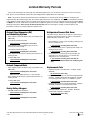
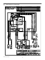
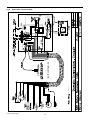
❖
SMX II Control Systems (DX)
INSTALLATION
For Direct Expansion SMX II Control Systems using SMXIIAB,
SMXir or the new SMXht keypad/displays.
Direct Expansion Systems
Revised: 12-6-04
L-2382 ❖ English
Table of Contents
SMX II Control Systems • Introduction
4
SMX II Control Systems • Installation
5
Installing the SMX Keypad/Display ................................................. 5
Installing the Power/Logic Box
(retrofit only) ................................................................................. 5
Installing the Temperature Sensor
(remote systems and retrofit only) ............................................... 5
SMX Interconnect Cable - Connecting
Keypad/Display To Power/Logic Board ........................................ 5
Pressure Switches
(retrofit only) ................................................................................. 6
Owner’s Limited Warranty
7
Limited Warranty Periods
9
Description of Figures
10
Copyright 2004 Dometic Corporation, All Rights Reserved - Every precaution has been taken in the preparation of this manual to insure its accuracy. However, Dometic Corporation assumes
no responsibility for errors or omissions. Neither is any liability assumed for damages resulting from the use of this product and information contained herein.
L-2382
3
❖ English
SMX II Control Systems • Introduction
Warning
This manual contains essential information concerning
the installation of your SMX II control system. It is very
important that you read and understand the contents of
this manual before using the equipment, and it should
be kept on the boat for future reference. If you have any
questions about the contents of this manual, contact
your local Cruisair dealer or the Dometic Service
Department for assistance.
Introduction
The term “SMX II” refers to the overall product family of
keypad/display controls and to the power/logic circuit board
located in the a/c unit’s electrical box. There are three different
keypad/displays that can operate an SMX II control system.
The three different keypad/displays are:
• SMXIIAB (previously known as SMX II) - rectangular in
shape and larger than the other two, this was the standard
for many years.
• SMXir - newer and smaller than the SMXIIAB, this control
has a hinged cover and an optional remote control.
• SMXht - the newest “High Technology” keypad/display, this
European style control fits into a decorative bezel and has
many new features.
If you have the SMXIIAB, SMXir, or SMXht keypad/display,
refer to the SMX II Control Systems (DX) Owner/Operator
manual (L-2362) before operating those controls.
If you have an SMX Net control system, refer to the SMX Net
Control Systems (DX) Installation and Operation manual.
L-2382 Introduction
4
❖ English
SMX II Control Systems • Installation
• The P/L box may be installed in any position.
Warning
• The P/L board dissipates heat when operating, and must
be installed in a ventilated location.
Make sure all power is off before opening any
electrical box.
• The P/L box is NOT waterproof and must be placed where
it will NOT get wet.
Installing the SMX Keypad/Display
The power input to the board can be 115V or 230V. The board
automatically adjusts to either voltage.
To be operated satisfactorily, the SMX keypad/display should
be installed so it is both visible and accessible. It should be
placed in plain view and within easy reach of the operator.
Overhead locations are discouraged since they make it very
difficult to use the SMX control.
Installing the Temperature Sensor
(remote systems and retrofit only)
The TSEP temperature sensor measures the cabin air
temperature and relays the information to the power/logic
board. The sensor is 1" long by ¼" diameter (25mm x 7mm
diameter) and is attached to a length of flat, 4-conductor cable
with a RJ-11 phone type plug at the end. Different lengths of
TSEP cables are available, from 2 feet to 80 feet (.6m to
24m).
Select a spot on an interior, vertical surface. This can be an
inside or outside wall, partition or other permanent structure
with rear access for wiring. The SMX control operates on low
voltage DC and is certified ignition-protected. The space
behind the SMX control does not have to be ventilated since
the control components do not produce heat.
For SMXir or SMXht keypad/display installations, refer to
drawings #086800 or #086810 in the back of this manual.
For best results, the sensor should be placed in the return air
path, away from the system evaporator coil. Directly behind
the return air grill is often a good location. The sensor must
not touch the evaporator coil, or be placed in the discharge air.
SMX II Only
The SMX II keypad/display requires a cutout of 29/16" x 71/8"
(65mm X 181 mm). After cutting the hole for the keypad
control, make sure it fits and the printed circuit board is clear
of the bulkhead and that no objects of any kind are in a
position to contact the SMX circuitry. Plug the interconnect
cable in and route it to the Power/Logic (P/L) box. Refit the
control in the hole and secure it with four No. 6 x 3/8 inch
screws. Hook the decorative plastic cover at the top, press it
flat from the top down, and snap it in place at the bottom.
With the TSEP in the return air path, use the default mode of
continuous fan operation for the most accurate temperature
control. If intermittent fan operation is desired (fan on and off
with the compressor), the sensor must be wall mounted on an
INSIDE surface not subject to any influence from heat outside
of the area (including direct sunlight). Thermistor covers are
available from Dometic Corporation for wall mounting.
SX self-contained units with integrated SMX II P/L box will
have the TSEP already installed. On FX remote units, the
TSEP must be run from the P/L box on the FX unit to the
return air path of the cooling unit.
Retrofitting SMXir Keypad/Display to
Original SMX II or 3-knob
Adapter plates are available to cover the old vertical or
horizontal rectangular cutout and mount the SMXir keypad/
display. Part #5103612 is a black plate, and #5103612W is
white. Use adapter #4163805 to connect an existing CX cable
to the SMXir display. (Refer to the SMXCABLE drawing at the
back of this manual.)
The TSEP cable plugs into the RJ-11 jack on the P/L board
marked “INSIDE TSE”. Coil up any excess cable, and tie out
of the way.
If you have a P/L board manufactured before 2000, you might
have a 3-pin TSE plug. Adapters are available to connect the
new TSEP cables to the old P/L boards. Refer to the
SMXCABLE diagram at the back of this manual.
Installing the Power/Logic Box
(retrofit only)
All SX and FX systems with integrated SMX II controls have
the P/L box already installed on the unit.
SMX Interconnect Cable - Connecting
Keypad/Display To Power/Logic Board
In selecting a location for the Power/Logic box, bear in mind
that several sets of wires will be connected to it. Refer to
installation diagrams in this packet.
Connection between the SMX II keypad and the Power/Logic
board should be made with a CX## cable. This is a shielded,
3-conductor cable with 4-pin plugs on each end. The plugs on
each end of the cable are identical, and are polarized. Make
sure all 4 pins are engaged in the plug.
• The SMX P/L board is ignition protected, enclosed, and
operates in ambient temperatures up to 130°F (54°C).
L-2382 Installation
5
❖ English
Systems with the SMXir keypad should use a CXP## cable.
These are flat cables with RJ-12 phone jack plugs on each
end.
Both CX and CXP cables are available in different lengths,
from 2 feet (.6m) to 80 feet (24m). Route the cable from the
power/logic board to the keypad. Plug the cable in at both
ends, and secure per low DC voltage standards.
Warning
The SMX interconnect (CX or CXP) and temperature
sensor cables (TSEP) transmit low voltage DC signals,
and outside interference can affect their operation. Do
not route these cables beside A/C power cables, high
voltage wiring, or antenna wires. Keep the cable runs as
short as possible to reduce the chance of interference.
Note
Standard phone cable will not work with SMX controls.
Pressure Switches (retrofit only)
Standard SX and FX units that have an integrated SMX II P/L
box include both the high and low pressure switches, already
connected. The SMX P/L board to pressure switch signals are
low voltage DC, and connections can be made with 22 gauge
or larger wire.
High-Pressure Switch: A high-pressure switch must be
connected to the SMX P/L board. Most marine A/C units have
a high-pressure switch that can be used for the SMX switch. It
should be disconnected from its in-line application, and
connected to the SMX P/L board at the push-on terminals
labeled “HIGH PRESS”.
The wires that were connected to the high-pressure switch
should then be butt connected together, effectively bypassing
the switch. The SMX II control will now monitor the switch and
shut the unit down if a high-pressure fault is sensed.
Low-Pressure Switch: A low-pressure switch is recommended
for SMX controlled systems, but is optional if the original unit
did not have a low-pressure switch.
To add a low-pressure switch, use Cruisair model A-201, and
either the A-204 sweat in TEE kit for remote condensing units
or the #4024100 service port TEE kit for ¼" flare ports, such
as on SH self-contained units.
Connect the wires from the low-pressure switch to the SMX
P/L board at the terminals labeled “LOW PRESS”.
If an existing low-pressure switch is used, bypass the switch
by butt connecting the old switch wires together.
L-2382 Installation
6
❖ English
Owner’s Limited Warranty
As hereinafter described, Dometic Corporation limits the duration of any implied warranty to the duration of the underlying
express warranty and also disclaims any liability for consequential or incidental damages arising from any application,
installation, use or malfunction of any warranted product.
Section I
rights is limited to the duration of the express warranty
as found in Section III. Some states do not allow limitations
on how long an implied warranty lasts, so the above limitation
may not apply to you.
What does the Limited Warranty cover?
Products manufactured by Dometic Corporation (Dometic) are
under limited warranty to be free from defects in workmanship
or materials under normal use and service with the obligation
of Dometic under this limited warranty being limited to
replacing or repairing any component(s) which shall disclose
defects within the time limits defined in Section III and which,
upon examination by Dometic, shall appear to the satisfaction
of Dometic to be defective or not up to specifications.
Section II
What does this Limited Warranty not cover?
This Warranty Shall Not Apply to:
1. Failures resulting from improper installation or use
contrary to instructions.
This Limited Warranty is made in lieu of all other express
warranties, obligations, or liabilities on the part of
Dometic. In addition, Dometic shall not be responsible
for any incidental or consequential damages. In those
instances in which a cash refund is made, such refund shall
effect the cancellation of the contract of sale without reservation of rights on the part of the purchaser. Such refund shall
constitute full and final satisfaction of all claims which
purchaser has or may have against Dometic due to any
actual or alleged breach of warranty, either express or
implied, including, without limitation, any implied
warranty of merchantability or fitness for a particular
purpose. Some states do not allow the exclusion or limitation
of incidental or consequential damages so the above limitation
may not apply to you. The terms and conditions of this
warranty shall be governed by the laws of the Commonwealth
of Virginia.
2. Failures resulting from abuse, misuse, accident, fire, or
submergence.
The Dealer is not an agent for Dometic except for the purpose
of administering the above warranty to the extent herein
provided, and Dometic does not authorize the dealer or any
other person to assume for Dometic any liability in connection
with such warranty, or any liability or expense incurred in the
replacement or repair of its products other than those
expressly authorized herein. Dometic shall not be responsible
for any liability or expense except as is specifically authorized
and provided in this section.
7. Warranty does not cover damage to components that
comprise a Custom Wrapped Box Evaporator refrigeration
system (aka: catch boxes, fish boxes, etc.) when the box
is installed in such a way that the customer can move it.
These damages may include, but are not limited to:
crimped refrigerant linesets (copper tubing or flexible
linesets), refrigerant leaks, moisture ingression into the
refrigeration system, subsequent damage to condensing
unit from being operated with low refrigerant charge or
moisture in the system, broken refrigerant connections,
broken thermostat sensors, and/or broken constant
pressure valves.
3. Any part manufactured by Dometic which shall have been
altered so as to impair its original characteristics.
4. Any parts which fail as a result of misuse, improper
application or improper installation.
5. Items not manufactured by Dometic, i.e., items which are
purchased from another manufacturer and supplied as
received by Dometic without alteration or modification
except as any part of an Dometic-manufactured unit or
component.
6. Components or parts used by or applied by the purchaser
as an integral part of products not manufactured by
Dometic.
Dometic reserves the right to improve its products through
changes in design or material without being obligated to
incorporate such changes in products of prior manufacture,
and to make changes at any time in design, materials, or part
of units of any one year's model, without obligation or liability
to owners of units of the same year's model of prior manufacture.
Installation and application of Dometic components is not
warranted by Dometic because Dometic has no control or
authority over the selection, location, application, or installation of these components.
This warranty gives you, the purchaser, specific legal rights,
and you may also have other rights which vary from state to
state. You also have implied warranty rights, including an
implied warranty of merchantability, which means that your
product must be fit for the ordinary purposes for which such
goods are used. The duration of any implied warranty
L-2382
Section III
What is the period of coverage?
See the Limited Warranty Periods, document # L-0694, for the
period of coverage.
7
❖ English
WARNING
All Dometic components bear a data plate on which there are
model and serial numbers. The serial number is date coded.
To determine whether or not any Dometic component is in
warranty, proceed as follows:
Dometic Corporation (Dometic) manufacturers of Cruisair, Grunert, Marine Air,
Sentry and Tundra Products, makes the following safety warnings concerning the
application, installation, use and care of its products. Although these warnings are
extensive, there may be specific hazards which may arise out of circumstances
which we have not outlined herein. Use this as a guide for developing an
awareness of potential hazards of all kinds. Such an awareness will be a key factor
in assuring your SAFETY and comfort.
1. Determine the manufacture date of the component from
the serial number on the data plate. If you are not familiar
with the date code, write or call the Dometic Customer
Service Department at (804)746-1313, to obtain the
manufacture date. The hours of the Customer Service
Department are 8:00 am - 5:00 pm (USA, Eastern Time
Zone) Monday through Friday excluding holidays.
ELECTRICITY - Many Dometic products operate on 115, 230 or 440 volt AC power.
Such voltages can be LETHAL; therefore, the chassis, cabinets, bases, etc., on all
components must be grounded together and connected to the vessel's grounding
system. Sparks can occur as switches, thermostats and relays open and close in
the normal operation of the equipment. Since this is the case, ventilating blowers
for the removal of hazardous fumes or vapors should be operated at least 5
minutes before and during operation of any Dometic product or group of Dometic
products. All electrical connections must be covered and protected so accidental
contact cannot be made by persons using the equipment, as such contact could be
LETHAL.
2. It is possible that there might exist a considerable time lag
between the date a component is manufactured and the
date it is put in service. In such instances, the date of
manufacture could indicate that the item is out of warranty.
However, based on the date the equipment is first put in
service, the item may still be covered by the Dometic
warranty described in Section I. For proof of date put in
service, Dometic will require a copy of the bill of sale of
the Dometic equipment from the installer or new boat
dealer to the original owner.
ELECTROLYSIS - Electrical leakage of any component can cause electrolytic
deterioration (electrolysis) of thru-hull components which could result in leakage
serious enough to sink a vessel which could result in loss of life. All Dometic
components must be kept clean and dry and checked periodically for electrical
leakage. If any electrical leakage is detected, the component should be replaced or
the fault causing the leakage corrected before the component is put back into
service.
GAS - CRUISAIR, MARINE AIR, GRUNERT and TUNDRA components utilize R-22
(Chlorodifluoromethane), R134a refrigerant (Tetrafluoroethane), R-407C (which
contains Diflouromethane (HFC-32), Pentafluoroethane (HFC125), and 1.1.1.2 Tetrafluoroethane (HFC134a)), R404A (R125/R143a/R134 (44%/52%/4%)), or
R417a, which are non-toxic, non-flammable gases; however, these gases contain
no oxygen and will not support life. Refrigerant gas tends to settle in the lowest
areas of the compartment. If you experience a leak, evacuate all personnel, and
ventilate area. Do not allow open flames in the area of leaks because refrigerant
gas, when burned, decomposes into other potentially LETHAL gases. Refrigerant
components operate at high pressure and no servicing should be attempted
without gloves, long-sleeved clothing and eye protection. Liquid refrigerant gas can
cause severe frost burns to the skin and eyes.
Section IV
How do you get service? Please Read the following Warranty Procedure.
WARRANTY PROCEDURE
VENTILATION - To cool or heat air, CRUISAIR, MARINE AIR and GRUNERT
components are designed to move air through a heat exchanger by a blower or
propeller fan. This design necessarily produces a suction on one side of the air
handling component and a pressure on the other side. Air handling components
must be installed so that the suction-pressure action does not: (1) pressurize an
area to the extent that structural failure occurs which could cause harm to
occupants or bystanders, or (2) cause a suction or low pressure in an area where
hydrogen gas from batteries, raw fuel vapor from fuel tanks, carbon monoxide from
operating propulsion engines, power generators or heaters, methane gas from
sewage holding tanks, or any other dangerous gas or vapor could exist. If an air
handling unit is installed in such a manner that allows potentially lethal gases or
vapors to be discharged by the air handling unit into the living space, this could
result in loss of life.
If the failure of a Dometic component is determined to be
covered under the Dometic warranty and the time in service is
determined to be within the warranty time limit, the owner has
the following three options:
1. Preferred option: Have a Dometic authorized Servicing
Dealer perform the work needed. The customer should
call Dometic's Service Department for a recommendation
as to the closest dealer. If the customer already knows an
authorized servicing dealer, the dealer should be contacted directly.
Maximum protection against the introduction of dangerous gases or vapors into
living spaces can be obtained by providing living spaces which are sealed from all
other spaces by use of airtight bulkheads and decks, etc., and through the
introduction of clean air into the living space. Bear in mind that the advent of air
conditioning, whether it be for cooling or for heating, naturally leads to the practice
of closing a living space tightly. Never close all windows and doors unless auxiliary
ventilating systems, which introduce clean outside air into the living space, are
used. Always leave enough window and door openings to provide adequate
ventilation in the event potentially lethal gases or fumes should escape from any
source.
2. If the customer contacts Dometic's Service Department
for a Servicing Dealer and Dometic has no one in that
particular area, Dometic will authorize the use of a local
service company and Dometic will work with the local
company to assist in any way possible.
CONDENSATE - All cooling units produce water condensate when operating on the
cooling cycle. This water must be drained from the cooling unit overboard. If
condensate is allowed to drip on a wooden structure, rotting or decay and
structural failure may occur which could result in loss of life. If condensate is
allowed to drip on electrical components, deterioration of the electrical components
could result in hazardous conditions. When an air conditioning system is in
operation, condensate drains may be subjected to negative pressure. Always
locate condensate drains as far as possible from points where engine waste and
other dangerous gases are exhausted so no such dangerous gases can be drawn
into the condensate drains.
3. The customer may send his equipment back to the factory
to have the repair work done. Dometic will make every
effort to return the equipment to the customer within a
three week time period. If the claim represents a legitimate warranty problem, Dometic will pay the freight both
ways. Dometic prefers option one and two, if at all
possible.
Warning
The customer may contact the Dometic Service Department
at (804) 746-1313.
L-0123
L-2382
Never sleep in a closed area on a boat when any equipment, which functions as a
result of the combustion of a volatile fuel, is in operation (such as engines,
generators, power plants, or oil-fired heaters, etc.). At any time, the exhaust system
of such devices could fail, resulting in a build-up of LETHAL gases within the
closed area.
Revised: 10-16-03
8
❖ English
Limited Warranty Periods
Please read and keep this document with your important paperwork. Use it as a reference in the future. If you have any questions, please contact the Dometic Corporation Service Department at (804)746-1313 for clarification.
Note: Any model or replacement part that has been installed due to a warranty failure will carry only the remainder of the
original warranty. All warranties begin when the customer takes possession of the equipment. The warranty is extended to all owners
of the equipment commencing the date the original owner takes possession of it. Proof of original purchase may be required. Fuses
and MOV’s are used as safety devices to protect Cruisair equipment against over-current conditions caused by lightning or inductive
switching environments. These are not covered under warranty. We reserve the right to change our warranty policies and
procedures as well as our warranty allowances without notice.
Cruisair Direct Expansion (DX)
and Modulating Systems
Refrigerators/Freezers/Fish Boxes
The below warranty periods do not apply to systems that are
installed as described in Section II, item #7, of the Owner’s
Limited Warranty, document # L-0123.
• New, complete system installation using any member of the
SMX family.
The warranty includes the pump.
• New installation of entire system including condensing unit,
line sets, evaporator, etc.
2 year warranty including Parts and Labor
1 year warranty including Parts and Labor
• New, complete system installation using an electromechanical control (3-knob).
• New complete model sold as a partial system retrofit to an
existing Cruisair system.
The warranty includes the pump.
1 year warranty including Parts and Labor
1 year warranty including Parts and Labor
• New installation of condensing unit only, with line sets,
evaporators, etc. done by others i.e. not Cruisair precharged line sets and evaporators.
• New, complete model sold as a partial system retrofit to an
existing system.
Includes SMX family.
1 year warranty including parts and labor on
mechanical and electrical parts of condensing unit
only.
1 year warranty including Parts and Labor
Cruisair Tempered Water
Replacement Parts
• New, complete system installation using any member of the
SMX family.
• Replacement parts and components - example: A-509,
40401-30.
2 year warranty including Parts and Labor
90 day warranty, Parts only
NOTE: Excludes pump which has a 1 year warranty
• Replacement Compressors for other than Tempered Water
Systems - example: R3101-16T, DX equipment - installed
in an existing Cruisair system or a competitor’s system.
• New, complete model sold as a partial system retrofit to an
existing system.
Includes SMX family.
1 year warranty including Parts and Labor
1 year warranty including Parts and Labor
• Replacement compressors for Tempered Water - example:
30130-36 installed in an existing Cruisair system.
1 year warranty including Parts and Labor
Sentry Battery Chargers
• A Tempered Water compressor - example: 30130-36
installed with competitor’s equipment.
• New SM and FR series installation.
2 year warranty including Parts and Labor
90 day warranty, Parts only
• New G-series installation.
1 year warranty including Parts and Labor
* The box denotes the part of the warranty that pertains to this particular product.
L-2382
9
Revised: 8-19-04 L-0694
❖ English
Description of Figures
Fig. 1
SXF5-16(C/CK); 115/230V, 50-60Hz
Dwg No. C0010001
Fig. 2
SXF24C; 230V, 50-60Hz
Dwg No. C0010003
Fig. 3
SXUF5-16(C/CK)/1-HV; 115/230V, 50-60Hz
Dwg No. C0010004A
Fig. 4
SXUF18(C/CK)/1-HV; 115/230V, 50-60Hz
Dwg No. C0010006A
Fig. 5
SXR7-16CK; 115/230V, 50-60Hz
Dwg No. 82570, P-967
Fig. 6
SX7-24CK; 115/230V, 50-60Hz
Dwg No. 082577, P-1023
Fig. 7
FX5-36CK; 115/230V, 50-60Hz
Dwg No. 083703, P-1048
Fig. 8
FX48RC; 230V, 50-60 Hz
Dwg No. 083704, P-1049
Fig. 9
FX20DC-FX48EC; 230V-460V, 3Ph, 50-60 Hz
Dwg No. 084901, P1050
Fig. 10 SMX II Retrofit, Typ. 3-knob
Dwg. No. 084001, P-1063 , A-284
Fig. 11 SMX II Retrofit, F20C-48RC, to 3-knob term. strip
Dwg No. 082605, P-1065,A-279
Fig. 12 SMX II Retrofit, F20C-48RC, to cond. unit
Dwg No. 082606, P-106, A-279
Fig. 13 SMXCABLE; Cable Diagrams; Old and New P/L Boards
Fig. 14 SMXir Mounting Template and Instructions
Dwg No. 086800, P-1077
Fig. 15 SMXht Keypad/Display Mounting Instructions and Dimensions
Dwg No. 086810
Fig. 16 Replacement DX SMX II Parts
Fig. 17 SMXir Remote Control Operation Range
Dwg No. SKA-1247-rev1
L-2382 Drawings/Diagrams
10
Fig. 1
SXF5-16(C/CK); 115/230V, 50-60Hz
L-2382 Drawings/Diagrams
11
Fig. 2
SXF24C; 230V, 50-60Hz
L-2382 Drawings/Diagrams
12
Fig. 3
SXUF5-16(C/CK)/1-HV; 115/230V, 50-60Hz
L-2382 Drawings/Diagrams
13
Fig. 4
SXUF18(C/CK)/1-HV; 115/230V, 50-60Hz
L-2382 Drawings/Diagrams
14
Fig. 5
SXR7-16CK; 115/230V, 50-60Hz
L-2382 Drawings/Diagrams
15
Fig. 6
SX7-24CK; 115/230V, 50-60Hz
L-2382 Drawings/Diagrams
16
Fig. 7
RX/FX5-36CK; 115/230V, 50-60Hz
L-2382 Drawings/Diagrams
17
Fig. 8
RX/FX48RC; 230V, 50-60 Hz
L-2382 Drawings/Diagrams
18
Fig. 9
RX/FX20DC-RX/FX48EC; 230V-460V, 3Ph, 50-60 Hz
L-2382 Drawings/Diagrams
19
Fig. 10 SMX II Retrofit, Typ. 3-knob
L-2382 Drawings/Diagrams
20
Fig. 11 SMX II Retrofit, F20C-48RC, to 3-knob term. strip
L-2382 Drawings/Diagrams
21
Fig. 12 SMX II Retrofit, F20C-48RC, to cond. unit
L-2382 Drawings/Diagrams
22
Fig. 13 SMXCABLE; Cable Diagrams; Old and New P/L Boards
L-2382 Drawings/Diagrams
23
Fig. 14 SMXir Mounting Template and Instructions
L-2382 Drawings/Diagrams
24
Fig. 15 SMXht Keypad/Display Mounting Instructions and Dimensions
Note: This drawing is
not to scale in this
manual.
L-2382 Drawings/Diagrams
25
Fig. 16 Replacement DX SMX II Parts
Fig. 17 SMXir Remote Control Operation Range
L-2382 Drawings/Diagrams
26
Dometic Corporation
Environmental Systems
P.O. Box 15299 • Richmond, VA 23227-0699 USA • Phone: 804-746-1313 • Facsimile: 804-746-7248
For Sales and Service Calls within Europe and the Middle East, please contact +44 (0) 870 330 6101
Email: [email protected] • Website: www.cruisair.com
L-2382