1
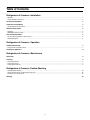
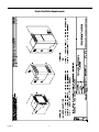
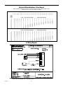
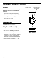
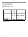
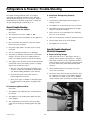
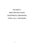
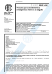
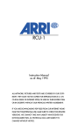
Refrigerators & Freezers
Tundra Technical Manual
Service & Training
Revised: 10-22-03
L-2120
Table of Contents
Refrigerators & Freezers • Installation
Warnings ........................................................................................................................................................................................................ 3
Tundra Installation Check List ......................................................................................................................................................................... 3
Locating the Dataplate
3
Inspection and Handling
3
Tundra Ventilation Requirements .................................................................................................................................................................... 4
Electrical Connection
5
DC Wiring ....................................................................................................................................................................................................... 5
DANFOSS Compressor Data ......................................................................................................................................................................... 5
Final Installation Notes
5
Electrical Wiring Guidelines - Direct Current .................................................................................................................................................. 6
DC Wiring Diagram ......................................................................................................................................................................................... 6
Refrigerators & Freezers • Operation
Temperature Control
7
Rotary Thermostat (Knob Control) .................................................................................................................................................................. 7
Loading the Appliance
8
Refrigerators & Freezers • Maintenance
Defrosting
9
Cleaning
9
Cleaning the Exterior ...................................................................................................................................................................................... 9
Cleaning the Interior ....................................................................................................................................................................................... 9
Cleaning the Condenser ................................................................................................................................................................................. 9
Refrigerators & Freezers • Trouble-Shooting
General Trouble-Shooting ............................................................................................................................................................................. 10
Specific Trouble-Shooting of Electrical Components ..................................................................................................................................... 10
For Questions or Service Call ....................................................................................................................................................................... 13
Warning
14
2
Refrigerators & Freezers • Installation
Warnings
• Carefully review all wiring diagrams included. If you purchase a
DC only Tundra Unit, simply wire your unit directly to the
appropriate DC power source. If you purchased an AC/DC
model, please refer to wiring diagrams to assure proper
installation per your individual application.
This section of the manual refers to essential safety
installation information for all compressor-type
refrigerators and freezers, (including Portable and
Special Purpose Units), provided by Dometic
Corporation.
• Make sure adequate ventilation is provided to
assure proper operation of your unit. See Ventilation
Requirements diagram in this manual.
1. When replacing old appliances, before disposing of the
old model, any locking device with hinging must be
removed so that the door cannot be accidentally locked.
All refrigerant must be removed according to current EPA
regulations.
• Once all of the above have been satisfied, you are ready to
enjoy your new Tundra Refrigerator or Freezer. For best
results, allow unit to run for 24 hours before loading with goods.
2. Unpacking and installation of the unit must be carried out
with the utmost care. To avoid accidental injury use
protective gloves, in particular for the models with a
remote condensing unit.
Locating the Dataplate
3. After unpacking the appliance ensure that it is not
damaged in any way. Notification of damage must be
supplied to the point of purchase no later than 24 hours
from the purchase date. The appliance must be used
exclusively for the conservation of food and drinks.
The dataplate bearing the model and serial number and
technical data is located on the upper right-hand section,
inside the appliance. (For Portable units, it is located on the
inside of the lid.) An additional, identical dataplate is
located on the compressor’s electronic module.
4. Install the appliance away from any heat sources and
allow for sufficient ventilation. See Ventilation Requirements diagram in this manual.
The first three digits of the serial number indicate the Year
and Week of manufacture.
5. After installation, wait at least one hour before switching
on the appliance. This precaution protects the compressor from shipping mishaps and ensures optimum
refrigeration efficiency.
Example: If your Serial Number = 0123456 it means:
0 = Year 2000
12 = 12th Week of the Year
3456 = Sequential Unit Number
IMPORTANT
All materials exposed to contact with food comply with EC
directive 89/109. Noise emission levels are maintained
below 70 dB(A).
Tundra Installation Check List
• Carefully remove unit from its packaging and inspect for
any damage that may have occurred in transit. If damage
is found, report it within the first 24 hours of taking
delivery. Please report this damage to your point of
purchase and the carrier responsible for handling.
Inspection and Handling
Ensure that the appliance is not damaged. Any damage
resulting from transport must be reported to the dealer no
later than 24 hours after delivery. A notice is printed on the
top of each box, describing the general procedures required.
• Be sure that all parts have been included. These parts
will consist of black mounting screws and a bottom
flange piece.
(NOTE: On T18 and T22 type units, the bottom flange
piece comes pre-assembled. Only on larger refrigerators and freezers will this bottom piece come as a
separate part. If your particular application calls for
the unit to sit on the ground when installed, this
bottom flange piece may not be required. )
Handle the appliance with care. Take care when positioning
the unit (especially in the case of refrigerators with remote
condensing units), to avoid any obstruction to the connection lines. Always ensure that the appliance and remote
condensing unit (where applicable), are installed on a dry,
flat surface that will not allow it to slide around.
• Stand unit upright for a minimum of 1 hour (before
applying power) to allow compressor oils to settle.
(NOTE: Though we state on our packaging to always
keep unit upright, we cannot control how the carrier
handles our boxes. This also applies if unit has been
set on its side to affix the bottom flange piece.)
Installation
Ventilation is a requirement for the condensing system.
Allow for air entry and discharge for the condensing system.
Air entry and discharge requires a minimum of 50 total sq.
inches each. (A T-80 unit requires a minimum of 75 total sq.
3
Tundra Ventilation Requirements
Installation
4
inches for air entry and discharge.) A lower entry, and
upper discharge is preferred. See Ventilation Requirements
diagram in this manual.
Overload Protections
The compressor overload and start protection cuts off
power to the compressor if the compressor speed drops
below approximately 1,900 rpm, or if this motor speed is
not reached during the start sequence. Possible reasons for
overload protection activating could be too high refrigeration system pressures during operation or lack of pressure
equalizing at start.
Install appliance away from heat sources in a dry and wellventilated area. Avoid direct contact with water. The
appliances are not waterproof.
Electrical Connection
The fan overload protection stops the compressor if the fan
current exceeds 0.5 A(avg) or 1 A(peak).
Before connecting the appliance to the power supply, check
that the line voltage corresponds to the indications on the
appliance rating plate and those of the compressor plate.
This appliance complies with EC directive 89/336 governing
radio suppression.
An overheating of the electronic unit heat sink will cause
the compressor to stop. Restart will occur automatically
when a normal temperature has been reached. If a fan is
installed, it will continue to run when the compressor stops
due to overload or electronic unit overheating.
DC Wiring
Voltage Protection
For Direct Current (DC) refrigerators, connect the appliance
to the DC distribution center. A circuit breaker of 15 Amps
(maximum) must be used if the system is 12VDC, and 10
Amps (maximum) if the system is 24VDC. Make sure that
proper polarity is maintained at all times. Check that all
grounding systems are in good working order. The appliance must be wired and grounded in accordance with
the Electrical Wiring Guidelines in this manual.
If a voltage outside any concerned range is applied to the
electronic unit, the compressor does not start, or it stops if
the voltage limit is exceeded during operation. The compressor will restart automatically approximately 1 minute
after the supply voltage has reached the reset voltage
within the range in question.
Battery Protection
The Danfoss electronic unit provides protection as follows:
DANFOSS Compressor Data
Standard Battery Protection Settings
Voltage Range
12V systems: From 10.4V to 17V
24V systems: From 22.8V to 31.5V
The electronic unit will calibrate automatically to the applied
voltage. This means that if the battery voltage is less than
17V, the electronic unit assumes that it is working in a 12V
system. If the voltage is higher than 17V, the electronic unit
assumes that it is working in a 24V system. However, the
compressor does not run at power supply voltages between
about 17V and 22.8V, the desired battery protection cut-out
voltage for 24V systems.
12V cut-in
24V cut-out
24V cut-in
10.4
11.7
22.8
24.2
Final Installation Notes
• For all appliances, AVOID the use of any electrical
adapters or extension cords.
• After installation, allow the appliance to sit for at least
one hour before starting.
Protection Systems
• The manufacturer assumes no responsibility for any
injuries or damage caused by noncompliance with
any of the installation regulations.
The Danfoss compressor protection system facilitates
protection against compressor overload and start failure,
fan overload and electronic unit overheating as well as
destructive battery discharge. When an overload protection
is activated, the compressor enters a cycle in which it
makes start attempts at approximately 60 second intervals
until a successful start is achieved.
Installation
12V cut-out
5
Electrical Wiring Guidelines - Direct Current
ABYC Guideline E9 (below) meets or exceeds Trucking Industry Standard SAE J1292
Conductor Sizes for 3 Percent Drop in Voltage
DC Wiring Diagram
* Note: T18 & T22 Models use a 277-ohm resistor.
Installation
6
Refrigerators & Freezers • Operation
Warnings
1. Coldest Setting
This section of the manual refers to essential safety
operation information for all compressor-type
refrigerators and freezers provided by Dometic
Corporation.
2. Adjustment Knob.
Turn Clockwise
• Before carrying out any maintenance or cleaning
operations, disconnect appliance from power supply via
the circuit breaker.
• Do not put glass containers holding liquids in the freezer
compartment.
• Dispose of packaging material in accordance with local
laws for sorted waste recycling.
Temperature Control
Each appliance is fitted with a manual thermostat which
automatically maintains set temperatures.
Rotary Thermostat (Knob Control)
1. Select desired temperature by means of the adjustment
knob.
2. The refrigerator is STARTED by turning the knob
clockwise. Temperature setting range is shown using a
band that thickens in the clockwise direction. The thicker
the band, the colder the setting.
Rotary Thermostat
Some models are fitted with thermostats with different
temperature scale markings than those described
above. In this case, lower the temperature, by turning
the knob clockwise.
3. To turn OFF the unit, turn the knob to “0” or “OFF”.
Operation
7
Loading the Appliance
Once you set the thermostat to a desired temperature,
allow the unit to RUN at least 12 hours (24 hours for best
results) before loading it with goods.
For proper food storage and conservation refer to the
table below:
Food
Meat or fish properly wrapped in
plastic
Storage Time
2 to 3 day
Position In Appliance
On the rack under the freezer
compartment
Eggs
1 week
Use door compartment
Butter, margarine
1 week
Use door compartment
Cooked food, cakes and soups
(in sealed containers and cooled)
3 to 4 days
On the lowest rack in the refrigerator
Cold cuts, cheese, fresh pasta,
pastries, cream, tomatoes,
puddings, chocolates, lard
3 to 4 days
On any rack
Fruit and vegetables
1 week
In the bottom of the refrigerator
The above are average storage times and can be affected by temperature settings, ambient temperatures, box
load and other external effects.
Operation
8
Refrigerators & Freezers • Maintenance
Defrosting
Defrosting should be carried out whenever the frost layer
exceeds a thickness of 1/8 inch. This is necessary to
guarantee efficient refrigeration and to avoid excessive
power consumption. Excess frost buildup will affect the
appliance’s performance.
To completely defrost, turn the appliance OFF. Keep the
door/lid open to minimize the defrosting time.
Do not attempt to remove the frost layer using any sharp
metal instruments. This could pierce the appliance plate
and cause irreparable damage to the appliance. Use warm
water or a hair dryer to melt frost.
After defrosting, dry the entire interior surfaces, and then
turn the appliance ON.
Cleaning
Before cleaning, disconnect the appliance from the power
supply. If necessary, remove the plug from the power
socket.
Cleaning the Exterior
Clean the exterior with warm and then with cold water. Dry
with a soft cloth. Avoid use of abrasive products.
Cleaning the Interior
Remove racks, containers, and ice trays. Clean the interior
using warm water mixed with baking soda or vinegar. Rinse
and dry carefully with a soft cloth. Do not use abrasive
products, detergents or soap. In the case of prolonged
disuse, to avoid the formation of mold or unpleasant odors,
remove plug from socket, empty the unit completely, clean
the interior, and leave the door/lid ajar.
Cleaning the Condenser
Clean the condenser at least once a year using a vacuum
cleaner or dry brush. Do not clean with sharp objects.
Maintenance
9
Refrigerators & Freezers • Trouble-Shooting
The trouble-shooting guidelines below are arranged
sequentially and should be followed in order. Start with
“General Trouble-Shooting” A, B & C; then go to “Specific
Trouble-Shooting of Electrical Components”, starting with
“A” and working through systematically to “F”.
C. Insufficient Refrigerating Capacity
Check that:
1. The door/lid is sealed properly and the hinges are
working correctly.
2. The appliance is not positioned close to heat sources.
General Trouble-Shooting
3. The appliance and remote refrigerating unit (if applicable) are sufficiently ventilated.
A. Appliance Does Not Operate
Check that:
4. Excess frost has not accumulated on the evaporator
(frost acts as an insulator).
1. The thermostat is not set to “STOP” or “OFF”.
5. Dust has not blocked the condenser ventilation sources.
2. The electrical system circuit-breaker for the appliance is
“ON”.
6. The fan rotates freely (in forced air models).
3. The fuse between the electronic control unit and the
power source has not blown.
7. The appliance is not over-full.
4. The power supply cable is not faulty, loose or poorly
connected.
Specific Trouble-Shooting of
Electrical Components
5. The fan is operating and there are no blockages.
A. Check Incoming Voltage
6. The battery is delivering sufficient power. If the battery
voltage is less than 10.4V (on a 12VDC system) or
22.8V (on a 24VDC system), the unit will not operate.
1. Hold meter leads to the “+” (the larger of the two “+”
symbols with the positive, red lead) and “–” (negative,
black lead) connections on the compressor module as
shown in Figure 1.0 and verify there is incoming power.
If not then check battery and/or alternative DC power
source(s).
7. The voltage on the electronic control unit terminal board
corresponds to that of the battery. If there is a voltage
drop of over 0.2-0.4V check that:
a. The size of the cable connecting the battery to the
electronic control unit corresponds to specifications
(see Electrical Wiring Guidelines in this manual).
2. Check that DC polarity is not reversed. If it is then
correct wire connections.
b. All connection points in the power circuit are
properly tightened and secure.
3. The inrush current must not drop more than 3% when
the compressor first comes on (per ABYC standards,
3% = 0.36 volts for 12VDC or 0.72 volts for 24VDC),
monitor volt/ohm meter at start-up. For 12VDC unit the
c. There are no signs of oxidation on the battery poles
or contact points and the battery is properly maintained.
B. Excessive Appliance Noise
Check that:
1. The appliance and refrigerating unit are positioned on
flat surfaces.
2. The appliance is not touching other objects that may
cause vibration.
3. The refrigerant lines at the back of the unit (if applicable) are not touching or vibrating against the appliance.
Figure 1.0 - Incoming Voltage
Trouble-Shooting
10
1 Flash = Battery protection cut-out (The battery
voltage was below the cut-out setting). Check the
source battery and/or alternative DC power
source(s) for proper operation and sufficient voltage
output. If power source is adequate then check wire
sizes against the Electrical Wiring Guidelines.
cut-out is 10.4 volts and the cut-in is 11.7 volts. For
24VCD unit the cut-out is 22.8 and the cut-in is 24.2. If
there is a drop in current, at start-up, below the cut-out
voltage then the compressor will not operate. A drop in
voltage will occur if the wire size is too small. Verify wire
size with Electrical Wiring Guidelines in this manual.
2 Flashes = Fan over-current cut-out (The fan
loads the electronic unit with more than 0.5 A(avg) or
1.0 A(peak)). Fan may be blocked, fan wires may be
loose or damaged or the fan motor has failed and is
drawing over-current to protect itself. Visually inspect
fan for blockage, check wires for chafes or loose
connections and repair. Or if fan has failed then
replace it (see item E. “Checking the Fan”).
4. Verify that voltage at unit is equal to voltage at source.
If the voltage at the unit is less than at the source then
the wire used from source to unit is too small. See
Electrical Wiring Guidelines.
B. Using Test Light to Check for Error Codes
The test light mentioned below is constructed of a 12
volt LED indicator light with two leads. One lead has a
push-on terminal connector and the other lead has a
piggy-back spade connector. The piggy-back is a female
push-on connector with a male spade for connecting
another push-on (shown in Figure 2.0 connected to the
small “+” terminal).
3 Flashes = Motor start error (The rotor is blocked
or the differential pressure in the refrigeration
system is too high [>72.5 psi]). Compressor may not
start because of high refrigerant pressure due to a
high heat situation. High ambient temperatures may
cause excessive heat, if so then the area around the
unit must be cooled down before trying to restart
compressor. Or, if compressor just cycled off, wait a
few minutes for pressure to come down and try
again.
4 Flashes = Minimum motor speed error (If the
refrigerant system is too heavily loaded, the compressor motor cannot maintain minimum speed
1,900 rpm). As above, this may happen when
system and/or ambient area is very hot which
increases refrigerant pressure. Solution is as above,
let area cool down and wait awhile before starting
unit.
5 Flashes = Thermal cut-out of electronic unit (If
the refrigeration system has been too heavily
loaded, and if the ambient temperature is high, the
electronic unit will run too hot). As with all electronics, the compressor module is sensitive to heat. The
module has a temperature sensor on the heat sink
and if it gets too hot, due to high amp draw or high
ambient temperatures, the unit will shut down.
Figure 2.0 -Test Light
1. The compressor module has a self-diagnostic program
built in. Connect a 10mA LED test light to terminals “D”
and “+” on the compressor module, that is, the terminal
with the smaller of the two “+” symbols. The fan lead will
need to be removed from terminal “+” and then reconnected on the piggy-back spade on the test light as
shown in Figure 2.0. In other words, both the fan lead
and the test light lead must be securely connected to
the “+” terminal. If there is a detectable error then the
LED light will flash 1 to 5 times and repeat the pattern.
Trouble-Shooting
If the test light shows 3, 4 or 5 flashes then verify that
there is adequate ventilation around the back of the
refrigerator/freezer (see drawing in this manual). Check
that vents are not blocked or dirty. Ensure that the unit
is not installed near a heat source.
11
Figure 3.0 - Thermostat Circuit
Figure 5.0 -Thermostat Resistor
C. Checking the Thermostat Circuit
Connect ohmmeter to either end of resistor assembly
(Figure 5.0). This is a 277-ohm resistor, verify that it is
operating properly to spec (with the 277-ohm resistor,
the control circuit current should be 4mA).
1. Remove brown & blue wires from terminal “C” and from
resistor connected to terminal “T”. Connect meter leads
to these wires as shown in Figure 3.0 - no polarity is
needed.
D. Checking the Compressor for Problems
2. If the thermostat is working correctly and calling for cool
then the ohmmeter should read zero (0) ohms (the
thermostat must not be in the “OFF” position). If there is
a reading other than zero then do the following:
1. Remove all wires from compressor module (make note
where they are connected, see wiring diagram).
2. Unscrew the one mounting screw from the module and
twist module to the rear to disconnect it from compressor.
a. Rotate the thermostat to the coldest setting and see
if that corrects the problem.
3. The compressor windings can be checked for defects
by measuring the resistances on the current lead-in
pins (Figure 6.0). If the measured values between all
pins are approximately the same, the compressor motor
is OK.
b. If there is still no continuity at the wires then unscrew and remove the thermostat control inside the
unit. Check that wires are not loose and check for
continuity on the thermostat itself (Figure 4.0). If
there is continuity at the thermostat, then there is a
problem with the wires leading back to the module. If
there is no continuity at the thermostat then it should
be replaced.
4. Also check each pin (motor winding) for continuity to
ground. If there is any continuity to ground then the
compressor is internally shorted and will need to be
replaced. This is not a field operation.
3. If there appears to be no problem above then check
the resistor that is connected to terminal “T”. This
resistor is used to set the compressor motor speed.
5. If a problem is not found in the compressor then the
module will need to be replaced.
Figure 4.0 - Thermostat Inside
Figure 6.0 - Compressor Pins
Trouble-Shooting
12
E. Checking the Fan
1.
The fan should come on after a five second delay once the
compressor starts.
2. Visually inspect fan for any blockages and make sure that it
can turn freely.
3.
If the fan can spin freely and is not working then first check
the fan terminals “+” (the smaller of the two ”+” symbols) and
“F” on the module for voltage (Figure 7.0).
4. If there is voltage at the module terminals then remove the fan
wires from the module and check for continuity through the
fan itself by placing meter leads in each fan wire push-on
terminal. If there is no continuity through the fan then replace
it.
Figure 7.0 - Fan Terminals
F. The Refrigerant Circuit
Marine Industry – call your dealer or distributor, or call the
factory and ask for the Tundra service dept:
For questions or service call:
1. If the refrigerator seems to be running properly and passes all
of the above tests and there is no cooling in the unit then the
problem may be a refrigerant leak.
Florida - 954-973-2477
Virginia - 804-746-1313.
Trucking Industry - call your dealer or call the factory:
2. Do not attempt to charge unit in field. Contact your
service dealer or Dometic Corporation at 804746-1313 or 954-973-2477. Ask for the Tundra
service department.
Virginia - 804-559-6404
Condenser Coil
Power Input
Compressor
Module
Cap Tube
(Expansion Device)
Compressor
Cooling Fan
Figure 8.0 - Refrigerant Circuit
Trouble-Shooting
13
Strainer
WARNING
pressure action does not: (1) pressurize an area to the extent that
structural failure occurs which could cause harm to occupants or
bystanders, or (2) cause a suction or low pressure in an area
where hydrogen gas from batteries, raw fuel vapor from fuel
tanks, carbon monoxide from operating propulsion engines, power
generators or heaters, methane gas from sewage holding tanks,
or any other dangerous gas or vapor could exist. If a unit is
installed in such a manner that allows potentially lethal gases or
vapors to be discharged by the air handling unit into the living
space, this could result in loss of life.
Dometic Corporation (Dometic) manufacturers of Cruisair,
Grunert, Marine Air, Sentry and Tundra Products, makes the
following safety warnings concerning the application, installation,
use and care of its products. Although these warnings are
extensive, there may be specific hazards which may arise out of
circumstances which we have not outlined herein. Use this as a
guide for developing an awareness of potential hazards of all
kinds. Such an awareness will be a key factor in assuring your
SAFETY and comfort.
ELECTRICITY - Many Dometic products operate on 115, 230 or
440 volt AC power and/or 12/24 volt DC power. Such voltages can
be LETHAL; therefore, the chassis, cabinets, bases, etc., on all
components must be grounded together and connected to the
vessel's or vehicle’s grounding system. Sparks can occur as
switches, thermostats and relays open and close in the normal
operation of the equipment. Since this is the case, ventilating
blowers for the removal of hazardous fumes or vapors should be
operated at least 5 minutes before and during operation of any
Dometic product or group of Dometic products. All electrical
connections must be covered and protected so accidental contact
cannot be made by persons using the equipment, as such contact
could be LETHAL.
Maximum protection against the introduction of dangerous
gases or vapors into living spaces can be obtained by
providing living spaces which are sealed from all other
spaces by use of airtight bulkheads and decks, etc., and
through the introduction of clean air into the living space.
Bear in mind that the advent of air conditioning, whether it
be for cooling or for heating, naturally leads to the practice
of closing a living space tightly. Never close all windows and
doors unless auxiliary ventilating systems, which introduce
clean outside air into the living space, are used. Always
leave enough window and door openings to provide
adequate ventilation in the event potentially lethal gases or
fumes should escape from any source.
ELECTROLYSIS - Electrical leakage of any component can
cause electrolytic deterioration (electrolysis) of thru-hull
components which could result in leakage serious enough
to sink a vessel which could result in loss of life. All Dometic
components must be kept clean and dry and checked
periodically for electrical leakage. If any electrical leakage is
detected, the component should be replaced or the fault
causing the leakage corrected before the component is put
back into service.
CONDENSATE - All cooling units produce water condensate when operating on the cooling cycle. This water must
be drained from the cooling unit overboard. If condensate is
allowed to drip on a wooden structure, rotting or decay and
structural failure may occur which could result in loss of life.
If condensate is allowed to drip on electrical components,
deterioration of the electrical components could result in
hazardous conditions. When an air conditioning system is in
operation, condensate drains may be subjected to negative
pressure. Always locate condensate drains as far as
possible from points where engine waste and other dangerous gases are exhausted so no such dangerous gases can
be drawn into the condensate drains.
GAS - CRUISAIR, MARINE AIR, GRUNERT and TUNDRA
components utilize R134a refrigerant, R409A or R404A,
R125/R143a/R134 (44%/52%/47%) which are non-toxic,
non-flammable gases; however, these gases contain no
oxygen and will not support life. Refrigerant gas tends to
settle in the lowest areas of the compartment. If you
experience a leak, evacuate all personnel, and ventilate
area. Do not allow open flames in the area of leaks because refrigerant gas, when burned, decomposes into other
potentially LETHAL gases. Refrigerant components operate
at high pressure and no servicing should be attempted
without gloves, long-sleeved clothing and eye protection.
Liquid refrigerant gas can cause severe frost burns to the
skin and eyes.
Warning
Never sleep in a closed area on a boat or vehicle when any
equipment, which functions as a result of the combustion of
a volatile fuel, is in operation (such as engines, generators,
power plants, or oil-fired heaters, etc.) At any time, the
exhaust system of such devices could fail, resulting in a
build-up of LETHAL gases within the closed area.
Rev. Date: 10-20-03 Tundra Version
VENTILATION - CRUISAIR, MARINE AIR, GRUNERT and
TUNDRA components are designed to move air through a
heat exchanger by a blower or propeller fan. This design
necessarily produces a suction on one side of the air
handling component and a pressure on the other side. Air
handling components must be installed so that the suction14
Notes:
Dometic Corporation
P.O. Box 15299 • Richmond, VA 23227-0699 USA
804-746-1313 • Facsimile: 804-746-7248 • www.tundra.cc
2000 N. Andrews Ave. Ext. • Pompano Beach, FL 33069-1497 USA
954-973-2477 • Facsimile: 954-979-4414
Fleets Industrial Estate • 26 Willis Way • Poole, Dorset BH15 3SU, England
+44(0)870 3306101 • Facsimile: +44(0)870 3306102
L-2120