1
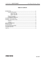
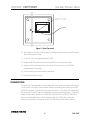
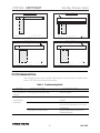
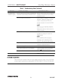
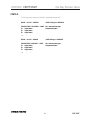
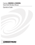
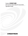
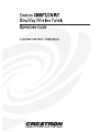
CRESTRON CNRFT/CNIRT
One-Way Wireless Panels
TABLE OF CONTENTS
DESCRIPTION................................................................................................................1
Functional Description......................................................................................1
CNRFT-32A/-48A..................................................................................1
CNIRT-32A/-48A...................................................................................1
Physical Description..........................................................................................2
Configuration Differences ................................................................................2
LEADING SPECIFICATIONS .......................................................................................3
CONTROLS AND INDICATORS..................................................................................4
Controls..............................................................................................................4
Indicators.............................................................................................................4
INSTALLATION/SETUP ...............................................................................................4
PROGRAMMING ...........................................................................................................6
TEST/TROUBLESHOOTING........................................................................................7
FURTHER INQUIRIES....................................................................................................8
SYNTAX .........................................................................................................................9
R E M O T E
C O N T R O L
S Y S T E M S
DOC. 8107
CRESTRON CNRFT/CNIRT
One-Way Wireless Panels
6.4 in
16.3 cm
8.8 in
22.3 cm
1
2
3
4
5
6
7
8
9
10
11
12
13
14
15
16
1
2
3
4
5
6
7
8
9
10
11
12
13
14
15
16
17
18
19
20
21
22
23
24
6.2 in
15.7 cm
6.2 in
15.7 cm
17
18
19
20
21
22
23
24
25
26
27
28
29
30
31
32
33
34
35
36
25
26
27
28
29
30
31
32
37
38
39
40
41
42
43
44
45
46
47
48
CRESTRON
CRESTRON
UNIT DEPTH 2.0 in (5.1 cm)
UNIT DEPTH 2.0 in (5.1 cm)
CNRFT-32A/CNIRT-32A
CNRFT-48A/CNIRT-48A
Figure 1. CNRFT/CNIRT, One-Way Wireless Panels
DESCRIPTION:
The CNRFT-32A/CNIRT-32A and CNRFT-48A/CNIRT-48A are a new improved version of CRESTRON's
one-way wireless panels. The new "A" units are functionally identical to the non-"A" units, but the newer
units have been completely redesigned for greater ease of installation and maintenance. The manual rotary
switches for ID code setting have been eliminated and replaced by a software utility program available
from CRESTRON's Workshop. The radio-frequency (RF) code packets have been updated to include error
detection for higher reliability reception. The new improved one-way wireless panels must be used with
CRESTRON's new CNRFGWA or CNIRGWA receiver. The standard, high-quality non-"A" version
transmitters must continue to use the CNRFGW or CNIRGW.
Functional Description
CNRFT-32A/-48A
The CNRFT series of portable RF wireless panels, figure 1, is designed to operate with the CRESNET II
system with the use of a wireless receiver such as the CNRFGWA network unit. Up to 32 miniature
pushbuttons reside on the CNRFT-32A to provide direct user interface. The CNRFT-48A offers up to 48
miniature pushbuttons.
CNIRT-32A/-48A
The CNIRT series of portable infrared (IR) wireless panels, figure 1, is designed to operate with the
CRESNET II system with the use of a wireless receiver such as the CNIRGWA network unit. Up to 32
miniature pushbuttons reside on the CNIRT-32A to provide direct user interface. The CNIRT-48A offers
up to 48 miniature pushbuttons.
R E M O T E
C O N T R O L
S Y S T E M S
1
DOC. 8107
CRESTRON CNRFT/CNIRT
One-Way Wireless Panels
Physical Description
CNRFT-32A/48A and CNIRT-32A/48A electronic hardware is housed in a high-impact molded plastic
enclosure (refer to figures 1 and 2 for front and back views, respectively ). The button array on the printed
circuit board is covered by a customized button panel. All button panels include custom engraving, colored
button caps, choice of button configurations, and panel finishes. Refer to the latest version of the
CRESNET II Engraving Worksheet for the wireless transmitters (Doc. 5242 and Doc. 5243) to design a
unique button panel. Omission of unused buttons is standard. A red transmit LED is located above the
button panel cover.
B AT T E R Y COVER REMOVED TO
SHOW SENSOR LOCATION.
B AT T E R Y COVER W B AT T E R Y
MOUNTED ON INSIDE OF COVER.
Figure 2. CNRFT/CNIRT, Back View
A standard nine-volt battery is included with all units. Access to the battery is permitted after the
battery cover, located on the underside of the unit, is removed. A sensor (photo transistor) used to
program an identity code is also located in the battery compartment.
Configuration Differences
The RF and IR one-way wireless transmitters have two different configurations based on the maximum
number of buttons available on the customized panel. They are depicted in table 1.
Table 1. CNRFT-32A/48A and CNIRT-32A/48A Configurations
CONFIGURATION
CNRFT-32A
CNRFT-48A
R E M O T E
C O N T R O L
S Y S T E M S
&
&
DESCRIPTION
CNIRT-32A
CNIRT-48A
32 buttons on a customized panel
48 buttons on a customized panel
2
DOC. 8107
CRESTRON CNRFT/CNIRT
One-Way Wireless Panels
LEADING SPECIFICATIONS:
Table 2 provides a summary of leading specifications for the wireless transmitters. Dimensions and
weight are approximations rounded to the nearest tenth unit.
Table 2. Leading Specifications
SPECIFICATION
DETAILS
Battery
CRESNET II Workshop
CRESNET II Operating System
CNRFT-32A & CNIRT-32A
Dimensions & Weight
9V DC
Version 5.0 or later
SR30160.OPS or later
Height:
6.2 in (15.7 cm)
Width:
6.4 in (16.3 cm)
Depth:
2.0 in (5.1 cm)
Weight: 0.7 lb (0.3 kg)
Height:
6.2 in (15.7 cm)
Width:
8.8 in (22.3 cm)
Depth:
2.0 in (5.1 cm)
Weight: 1.0 lb (0.5 kg)
CNRFT-48A & CNIRT-48A
Dimensions & Weight
NOTE
This equipment has been tested and found to comply with the limits for a Class B
digital device, pursuant to part 15 of the FCC Rules. These limits are designed to
provide reasonable protection against harmful interference in a residential
installation. This equipment generates, uses and can radiate radio frequency energy
and, if not installed and used in accordance with the instructions, may cause harmful
interference to radio communications. However, there is no guarantee that
interference will not occur in a particular installation. If this equipment does cause
harmful interference to radio or television reception, which can be determined by
turning the equipment off and on, the user is encouraged to try to correct the
interference by one or more of the following measures:
-
Reorient or relocate the receiving antenna.
-
Increase the separation between the equipment and receiver.
- Connect the equipment into an outlet on a circuit different from that to which the
receiver is connected.
-
R E M O T E
C O N T R O L
S Y S T E M S
Consult the dealer or an experienced radio/TV technician for help.
3
DOC. 8107
CRESTRON CNRFT/CNIRT
One-Way Wireless Panels
CONTROLS AND INDICATORS:
Controls
Button controls are custom designed. The wireless transmitters are available with a maximum of 32 to
48 functional buttons (depending on the model). Function definition is determined by application of the unit
within the CRESNET II system. The customized button controls correspond to signal names that are
defined in the SIMPL program.
Indicators
There is only one indicator located on the wireless transmitters. The indicator is a red LED and resides on
the face of the unit above the button panel cover. The transmit LED indicates IR/RF transmission and
illuminates when a button is depressed.
INSTALLATION/SETUP:
Every wireless transmitter communicating with either the CNRFGWA or CNIRGWA requires a unique
identity code (ID CODE). For RF devices the ID CODE is referred to as RF ID. For IR devices the ID CODE is
referred to as IR ID. There are 254 possible two-digit hexadecimal alphanumeric codes ranging from 01 to
FE. The CNRFT/CNIRT ID CODE is factory set to 11, but may be changed from a PC via CRESTRON's
CRESNET II Workshop. An ID CODE may need to be changed if more than one transmitter is placed on the
network. To maintain code diversity within the CRESNET II system, use codes between 10 and FE for the
transmitters.
NOTES
1.
The ID CODE on the wireless transmitters is factory set to 11.
2.
If an ID CODE needs to be changed, do not use 00 or FF as an RF/IR ID.
3.
Do not confuse RF/IR ID with network (NET) ID.
The following items are required to change the wireless transmitter ID CODE:
•
PC running CRESNET II Workshop, version 5.0 or later.
•
CNIDC - Identity Code cable.
Complete the following steps in the order provided to ensure proper ID CODE assignment of the unit.
1.
Start up the CRESNET II Workshop with the following DOS commands.
CD\CN2 (depress ENTER)
CNWS (depress ENTER)
2. The Workshop commences with an opening screen. Depress any key to open the MAIN MENU,
illustrated in figure 3.
R E M O T E
C O N T R O L
S Y S T E M S
4
DOC. 8107
CRESTRON CNRFT/CNIRT
One-Way Wireless Panels
3. From the MAIN MENU, highlight Utilities and depress ENTER. The UTILITY MENU, illustrated in
figure 4, appears on the display.
CRESNET
II
Workshop
CRESNET
v5.0
II
Workshop
UTILITY
MAIN
ESC
to
Transmitter ID Programmer
the SIMPL (Symbol - Intensive - Master - Programming Language) program development environment.
Quit
Alt[D]
=
Set
Defaults
ESC
F1=Help
Figure 3. MAIN MENU, Workshop
4.
MENU
performance Viewport
load/save Touch panels
Print touch panel
OS Upgrade
CPU
DEAL
Easykey programmer
load/save Nvram
TID
Leave Utilities
MENU
SIMPL
RIPE
Sort IR drv
Utilities
Quit
Enter
v5.0
to
Main
Menu
Alt[D]
=
Set
Defaults
F1=Help
Figure 4. UTILITY MENU, Workshop
From the UTILITY MENU, highlight TID and depress ENTER. The Transmitter ID Programmer,
illustrated in figure 5, appears on the display.
CRESNET
II
Workshop
v5.0
Transmitter ID Programmer
Position IR probe over sensor on transmitter.
RS-232 COM port: COM1
Type RF id code in HEX:
Hit Enter to program the transmitter ID
Do not remove IR probe until it stops blinking
F1-Help
TAB-Select COM
Enter-Program the transmitter
ESC-Utility
Menu
Figure 5. Transmitter ID Programmer, Workshop
R E M O T E
C O N T R O L
5.
From the Transmitter ID Programmer screen, specify the PC's COM port with the TAB key.
6.
Connect the 9-pin DIN connector from the CNIDC to the proper COM port on the back of the PC. Use
the same port as that assigned in the previous step.
7.
Position the transmitter button-side down so the battery compartment is accessible.
8.
Remove the battery cover to expose the battery compartment. Refer to figure 2.
9.
Place LED probe from the CNIDC over the exposed sensor (photo transistor) as shown in figure 6. The
probe should rest in the corner of the battery compartment so that it completely covers the sensor.
S Y S T E M S
5
DOC. 8107
CRESTRON CNRFT/CNIRT
One-Way Wireless Panels
PROBE SHOULD COVER
SENSOR A S SHOWN.
Figure 6. Probe Placement
10. With a finger over the probe to hold it in place, lift and rotate transmitter so that the red LED located
above the button panel is visible.
11. From the PC, type the two-digit hexadecimal ID CODE.
12. Depress the ENTER key and observe the flashing red LED on the front of the transmitter.
13. When the red LED stops flashing, remove the probe from the back of the unit. The ID CODE is
programmed into the transmitter.
14. Secure the battery cover over the battery compartment.
15. Disconnect the CNIDC from the PC.
PROGRAMMING:
The button array is located beneath the custom button panel of each wireless transmitter. Refer to figure
1 for the location of the SIMPL-C button numbers and their corresponding button positions for the CNIRT
and CNRFT transmitters. The numbering for each button is constant. For each button input, a signal name
must be defined in the SIMPL program. Unused buttons need not be assigned signal names. The following
example illustrates button definition of the CNRFT-32A and CNIRT-32A in the CRESNET II Workshop.
Access the following tables from the "Define Network" section of the SIMPL-I Menu. Aside from
difference in nomenclature, the Workshop menus of the CNRFT-48A and CNIRT-48A are identical.
R E M O T E
C O N T R O L
S Y S T E M S
6
DOC. 8107
CRESTRON CNRFT/CNIRT
CRESNET
II
Workshop
One-Way Wireless Panels
CRESNET
v5.0
System PF : 3.0
Net
PF:
II
Workshop
v5.0
3.0
Net ID: 03
Net ID
03:
04:
05:
06:
07:
08:
09:
0A:
0B:
0C:
0D:
0E:
0F:
10:
11:
12:
ESC
to
Net Device
Description
CNRFGW
P.F.
CNRFGW/CNIRGW Receiver
CNRFGW
CNRFGW/CNIRGW Receiver
3.0
12
14
TAB to select entries
F2-Detail
Def Equip
PgUp/PgDn to find ID
F3-Display Signals
Define Network
F1=Help
CRESNET
II
Workshop
ESC
CNRFGW
F2-Detail
to Define Net
Description
32-button 1-way transmitter
32-button 1-way IR transmitter
TAB - Select Transmitter
Panel Detail
CRESNET
Net ID: 03
II
Workshop
v5.0
CNRFGW
BUTTON SIGNAL NAMES
to Enter ID
F1=Help
Net ID: 03
CNIRT-32
RF ID: 14
BUTTON SIGNAL NAMES
1:
2:
3:
4:
5:
6:
7:
8:
9:
10:
11:
12:
13:
14:
1:
2:
3:
4:
5:
6:
7:
8:
9:
10:
11:
12:
13:
14:
F2-Detail
to
CNRFT-32
CNIRT-32
v5.0
CNRFT-32
RF ID: 12
ESC
Transmitter
RF ID
F3-Display Signals
Define Net
Panel Detail
F4- Auto-Increment
F2-Detail
F1=Help
ESC
to
F3-Display Signals
Define Net
Panel Detail
F4- Auto-Increment
F1=Help
TEST/TROUBLESHOOTING:
Table 3 provides corrective action for possible trouble situations. If further assistance is required, please
contact a CRESTRON technical support representative.
Table 3. Troubleshooting Guide
TROUBLE
LED on unit does not
illuminate.
Intermittent
response during
transmission.
POSSIBLE CAUSE(S)
No battery in unit or battery is dead.
CORRECTIVE ACTION
Install new battery.
Refer to cause when LED does not illuminate.
Refer to corrective action when LED does not
illuminate.
For IR unit, verify direct line-of-sight. For RF
unit, verify that heavy metal is not in vicinity
of transmission.
Verify that large amount of metal is not
blocking transmission.
Receiver is blocked or moved.
CNRFGWA is in vicinity of metal.
R E M O T E
C O N T R O L
S Y S T E M S
7
DOC. 8107
CRESTRON CNRFT/CNIRT
One-Way Wireless Panels
Table 3. Troubleshooting Guide (Continued)
TROUBLE
No response from
CRESNET II system.
POSSIBLE CAUSE(S)
CORRECTIVE ACTION
Refer to causes when LED does not illuminate and Refer to corrective action when LED does not
intermittent response during transmission occurs. illuminate and intermittent response during
transmission occurs.
NET ID of receiver is incorrectly set.
Enter Performance Viewport in the CRESNET II
Workshop. Depress the F4 key to poll the
network. Verify that the NET ID for the
receiver is properly set to match the SIMPL
program.
NOTE:
After changing the CNRFGWA/CNIRGWA
identity code, disconnect and reconnect the
network connector.
RF ID or IR ID is incorrectly set.
Verify that the RF ID or IR ID for the
transmitter is properly set to match the
SIMPL program.
NOTE:
NET ID and RF ID or IR ID are separate
parameters. ALT-R in Workshop (v5.0)
shows RF or IR transmitter button presses.
Program does not match hardware.
Verify correct program is loaded in system via
Performance Viewport Workshop.
Receiver is unplugged (no power).
Verify power to the receiver.
Two or more receivers are too close together.
Verify that multiple receivers are properly
spaced (>50 feet) from each other.
Wrong transmitter in use.
If multiple transmitters are accessible, verify
proper unit is used.
FURTHER INQUIRIES:
If after reviewing this Operations Guide you still have additional questions, please contact a CRESTRON
technical support representative by dialing (888) CRESTRON [(888) 273-7876] or (201) 894-0660.
R E M O T E
C O N T R O L
S Y S T E M S
8
DOC. 8107
CRESTRON CNRFT/CNIRT
One-Way Wireless Panels
SYNTAX:
The following syntax codes are provided for compatibility purposes only.
NET.ID <10 o FE>: CNRFGW
\CNRFT talking to a CNRFGWA
TRANSMITTER <RF IDCODE >: CNRFT \ID # and transmitter type.
i1 = <signal name>
\Independent button.
i2 = <signal name>
i3 = <signal name>
" =
"
"
R E M O T E
C O N T R O L
NET.ID <10 o FE>: CNIRGW
\CNIRT talking to a CNIRGWA
TRANSMITTER <IR IDCODE >: CNIRT
i1 = <signal name>
i2 = <signal name>
i3 = <signal name>
" =
"
"
\ID # and transmitter type.
\Independent button.
S Y S T E M S
9
DOC. 8107