1
Crestron SIMPL Windows
Primer
This document was prepared and written by the Technical Documentation department at:
Crestron Electronics, Inc.
15 Volvo Drive
Rockleigh, NJ 07647
1-888-CRESTRON
All brand names, product names and trademarks are the property of their respective owners.
© 2003 Crestron Electronics, Inc.
Crestron SIMPL Windows
Software
Contents
CRESTRON SIMPL WINDOWS.................................................................................. 1
Overview...................................................................................................................................1
About this Primer.......................................................................................................................1
Crestron Development Software ............................................................................................2
SIMPL Windows .......................................................................................................................2
Crestron VisionTools® Pro-e ....................................................................................................2
DEAL™ for Windows...............................................................................................................2
Media Manager™ System Builder™.........................................................................................3
D3 Pro™....................................................................................................................................3
Databases ...................................................................................................................................3
Product Catalog CD...................................................................................................................3
Crestron Control Systems .......................................................................................................5
Why Program Control Systems?................................................................................................5
Elements of a Control System ...................................................................................................5
Main Processor ..........................................................................................................................5
Network Control Modules .........................................................................................................6
Plug-in Control Cards ................................................................................................................6
User Interfaces ...........................................................................................................................6
User devices...............................................................................................................................7
Control Methods ......................................................................................................................7
Relay closures............................................................................................................................7
Serial Communications..............................................................................................................8
IR (Infrared)...............................................................................................................................8
Custom Serial ..........................................................................................................................10
RS-232, RS-422, and RS-485 ..................................................................................................10
MIDI (Musical Instrument Digital Interface) ..........................................................................11
Analog Voltages ......................................................................................................................12
Custom Crestron Interfaces .....................................................................................................12
Cresnet .....................................................................................................................................12
SIMPL WINDOWS PROGRAMMING........................................................................ 15
Introduction to SIMPL..........................................................................................................15
Symbol Categories...................................................................................................................15
Device Symbols .......................................................................................................................15
Logic Symbols .........................................................................................................................16
Symbol Properties....................................................................................................................16
Inputs .......................................................................................................................................16
Outputs.....................................................................................................................................16
Parameters ...............................................................................................................................16
Signal Types ............................................................................................................................17
Digital Signals .........................................................................................................................18
Analog Signals.........................................................................................................................18
Primer – DOC. 6253
Contents • i
Software
Crestron SIMPL Windows
Serial Signals ...........................................................................................................................18
Special Signals ‘0’ and ‘1’.......................................................................................................19
Logic Waves and Logic Solutions ...........................................................................................19
Programming with User Interfaces......................................................................................20
Button Presses..........................................................................................................................20
Button Feedback ......................................................................................................................21
Subpages (touchpanels only) ...................................................................................................22
Analog displays (touchpanels only).........................................................................................23
Indirect text (touchpanels only) ...............................................................................................23
Building a Program with SIMPL Windows ........................................................................24
Programming Process ..............................................................................................................24
Basic Programming Rules .......................................................................................................24
Build a System.........................................................................................................................24
Control Systems.......................................................................................................................26
Network Hardware...................................................................................................................27
Plug-in Control Cards ..............................................................................................................28
Serial Devices ..........................................................................................................................29
User Devices............................................................................................................................29
Network IDs ............................................................................................................................30
Configure Devices ...................................................................................................................30
Cresnet Devices .......................................................................................................................30
Ethernet Devices......................................................................................................................32
Serial Devices ..........................................................................................................................33
Touchpanels.............................................................................................................................33
Connecting Signals ..................................................................................................................34
Define Signals from User Interface .........................................................................................34
Using Logic Symbols ..............................................................................................................36
PROGRAMMING WITH LOGIC SYMBOLS ............................................................. 37
Introduction ...........................................................................................................................37
Types of Logic Symbols.........................................................................................................37
Basic Logic..............................................................................................................................38
NOT Symbol............................................................................................................................38
NOT Symbol Example: Automatic Camera Control ...............................................................39
OR Symbol ..............................................................................................................................39
OR Symbol Example: Volume Un-mute .................................................................................39
AND Symbol ...........................................................................................................................40
AND Symbol Example: discrete power on/off ........................................................................40
Buffer Symbol .........................................................................................................................41
Buffer Example: multi-device control .....................................................................................42
Buffer Example: triggering multiple events.............................................................................43
State Logic ..............................................................................................................................46
Set/Reset Latch symbol ...........................................................................................................47
Set/Reset Latch Example: System Power Relay......................................................................47
Toggle Symbol.........................................................................................................................47
Toggle Example: Volume Mute...............................................................................................48
Toggle Example: Device Power On/Off..................................................................................48
Interlock Symbol .....................................................................................................................49
Interlock Example: Source Selection Feedback.......................................................................49
ii • Contents
Primer – DOC. 6253
Crestron SIMPL Windows
Software
Time-based Logic...................................................................................................................52
One Shot Family ......................................................................................................................52
One Shot ..................................................................................................................................52
Multiple One Shot....................................................................................................................53
Retriggerable One Shot............................................................................................................53
Delay Symbol ..........................................................................................................................54
Oscillator Symbol ....................................................................................................................55
Analog Logic ..........................................................................................................................57
Analog Ramp Symbol..............................................................................................................57
Analog Initialize ......................................................................................................................58
Analog Preset Symbol .............................................................................................................60
Serial/Analog One-Shot...........................................................................................................61
Modules ...................................................................................................................................63
Communication Settings..........................................................................................................63
Compiling and Uploading Programs .......................................................................................65
Software License Agreement ................................................................................................67
Return and Warranty Policies..............................................................................................69
Merchandise Returns / Repair Service.....................................................................................69
CRESTRON Limited Warranty...............................................................................................69
Primer – DOC. 6253
Contents • iii
Crestron SIMPL Windows
Software
Crestron SIMPL Windows
Overview
About this Primer
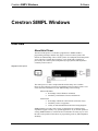
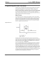
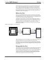
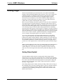
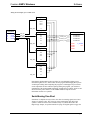
The intent of this primer is to introduce programmers to SIMPL Windows
programming techniques and how they apply to Crestron control systems. This
includes an understanding of how control systems use touchpanels and button panels
as user interfaces. Through these interfaces, a user might send a signal that is
processed by the control system (manipulated by logic symbols) and outputted to
eventually control a device.
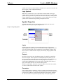
Simplified Control System
The control process is more complex than this and has many more variables.
However, this is the basic concept of programming Crestron control systems. Users
of this information should have a basic understanding of the following:
Microsoft Windows
•
•
Knowledge of basic Windows commands
Familiarity with Windows features and functions
Audio/Visual
•
•
•
Knowledge of different control formats (serial, IR, relays)
Familiarity with A/V equipment
Ability to read and understand control and wiring diagrams
SIMPL Windows provides a wide variety of symbols that are constantly being
expanded to support virtually every possible application. As you become proficient
at using SIMPL Windows it will become obvious that there are many ways to solve
the same control problem. This allows for programming creativity and independent
flexibility.
Primer – DOC. 6253
Crestron SIMPL Windows • 1
Software
Crestron SIMPL Windows
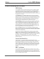
Crestron Development Software
SIMPL Windows
Crestron SIMPL Windows provides all the tools necessary to configure, program,
test and debug an integrated control system application. Combining the familiar
drag-and-drop functionality of Microsoft Windows with the programming power of
SIMPL (Symbol Intensive Master Programming Language), SIMPL Windows
provides the link between Crestron systems hardware, user interfaces, and the world
of equipment to be controlled.
The configuration aspect of SIMPL Windows allows you to select the control
system, user interfaces, network devices and controlled equipment required for the
installation. To these hardware components you can assign port addresses, Network
IDs and IP addresses, set communication parameters and specify which device is
connected to which card or network control module. You can also specify what
VisionTools™ Pro-e touchpanel projects are required for the system.
The programming aspect allows you to select the logic symbols the system will
require, assign signals to those symbols and connect the signals to other symbols or
devices as determined by the program logic. SIMPL Windows includes a wide
variety of symbols that are constantly being expanded to support virtually every
possible application. As you become proficient at using SIMPL Windows it will
become obvious that there are many ways to solve the same control problem. This
allows for programming creativity and independent flexibility.
Finally, the testing aspect allows you to test and debug your SIMPL Windows
program using powerful diagnostic tools including Test Manager, Network Analyzer,
and the Crestron Viewport. You can call these tools directly from SIMPL Windows
or launch the tools independently.
For even greater flexibility, the SIMPL Windows installation package includes
SIMPL+™, a development tool that allows advanced programmers to create and
compile custom control modules using a procedural language similar to C. You can
add SIMPL+ modules to your SIMPL Windows program or user module much like a
logic symbol, to extend functionality or solve a specific control problem.
SIMPL Windows is fully integrated with Crestron's suite of software tools, which
include the following:
Crestron VisionTools® Pro-e
VisionTools® Pro-e is Crestron's touchpanel page design software. Using
VisionTools Pro-e, programmers can create powerful touchscreen control interfaces
that include pop-up subpages for specific device transport controls, multi-mode
buttons and sliders with 3D effects, high-resolution graphics, dynamic text, video
windows, sound, and more. VisionTools Pro-e uses join numbers to identify button
presses, feedback, and other digital, analog and serial signals. These join numbers
correspond to inputs and outputs on the touchpanel symbol detail in SIMPL
Windows.
DEAL™ for Windows
Crestron's DEAL™ (Device Editor and Learner) for Windows software enables
programmers to learn manufacturer's IR signals. When used in conjunction with the
Crestron CNXLIR (IR Learner), DEAL allows you to create, modify and test IR
driver files, and to save the learned IR files in the User Database where you can add
them to your SIMPL Windows program.
2 • Crestron SIMPL Windows
Primer – DOC. 6253
Crestron SIMPL Windows
Software
Media Manager™ System Builder™
The Media Manager™ System Builder™ offers automatic programming for such
residential and commercial applications as audio distribution, home theater, and
video conferencing. The System Builder provides a Wizard-like interface that takes
you through a series of programming screens. Simply follow the prompts to select
the control system, user interfaces, devices and functionality. The System Builder
then automatically programs, compiles, and uploads the system, including
VisionTools Pro-e touchpanel projects and control system logic.
D3 Pro™
Crestron D3 Pro™ software offers design, development, and documentation for a
complete residential lighting system, with additional support for auxiliary devices
such as security systems, motion detectors and shades. Like the System Builder, D3
Pro presents a Wizard-like interface. Programming is accomplished through a series
of simple but powerful System View screens. After the design is complete, D3 Pro
automatically creates, compiles, and uploads the control system program and
touchpanel projects.
These are just some of the software tools that Crestron has created to help you
accomplish your programming tasks more easily and efficiently. You can download
all Crestron software for free from the Software Updates area of the Crestron Web
site (requires registration).
Databases
The Crestron Database is a large collection of information that is accessed by
various Crestron software packages, including SIMPL Windows, D3 Pro, and the
System Builder. The bulk of the Database consists of IR driver files that control user
devices such as CD players, DVD players, conferencing equipment, and other thirdparty IR devices the end user interfaces with using the Crestron control system.
In addition to IR driver files, the Crestron Database contains hundreds of Crestron
logic modules that control third-party device functions. Modules are self-contained
logic programs that have been pre-coded, tested and debugged at Crestron. These
dedicated modules can be plugged into a program and used to generate all the proper
control codes for a device automatically.
The User Database is designed to store IR driver files that are not included in the
Crestron Database. Programmers usually generate IR files using the Crestron
CNXLIR (IR Learner) in conjunction with DEAL (Driver Editor and Learner) for
Windows software. Alternatively, you can obtain user IR files by downloading them
from the Crestron Design Center or Crestron FTP site.
In addition to IR driver files, the User Modules directory stores user-created logic
modules that are not included in the Crestron Database.
Product Catalog CD
Crestron provides a variety of ways for you to obtain information about Crestron
hardware. The most comprehensive resource is the Crestron Web site:
www.crestron.com. Here you can download the most up-to-date user manuals,
reference guides, and CAD drawings for all Crestron control systems, network
devices and touchpanels. You can also access the Crestron Design Center, which
provides extensive information about user modules that control equipment from I2P
partner manufacturers, including help files, sample logic programs, touchpanel
projects, cable diagrams, and more.
Primer – DOC. 6253
Crestron SIMPL Windows • 3
Software
Crestron SIMPL Windows
You can access the Crestron Web site directly from the SIMPL Windows Online
Support menu. Click Crestron Online for the Crestron home page, or click
Crestron Design Center to open the Dealer/Tech Resources page.
The Crestron Product Catalog and Technical Reference CD is another valuable
tool that you can use in conjunction with the Crestron Web site, or any time you're
not connected to the Internet. The CD is a comprehensive library of Crestron
brochures, catalogs, product specification sheets, CAD drawings and user manuals.
You can browse the CD independent of any Crestron program, or you can link the
CD directly to SIMPL Windows to display documentation for devices you select in
the Device Library.
To access user manuals from SIMPL Windows
4 • Crestron SIMPL Windows
1.
Insert the Product Catalog CD into the CD-ROM drive (you can close the
selection screen if it opens automatically).
2.
In the SIMPL Windows Device Library, select whichever Crestron control
system, network device, touchpanel or control card you want documentation
for and press F1.
3.
The first time you try to access the Product Catalog CD from SIMPL
Windows you will be prompted to browse for the CD-ROM drive or folder
where the CD is located. Locate the drive or folder and click Open.
4.
If documentation is available for the selected device, SIMPL Windows will
find the PDF file and open it in Adobe Reader. If no PDF file is available
for the device, then the SIMPL Windows help file will display
programming help for the device.
5.
You can click Product Catalog CD on the SIMPL Windows Help menu
any time you want to open the CD selection screen for documents,
brochures, CAD drawings, or utilities.
6.
If you do not have the CD inserted and you press F1 on a device in the
Device Library, SIMPL Windows will prompt you to insert the CD. You
can then either insert the CD or click Cancel to view the online help file.
Primer – DOC. 6253
Crestron SIMPL Windows
Software
Crestron Control Systems
Why Program Control Systems?
The term program refers to the instructions loaded into the control processor that
cause it to operate in an intended way. For example, to control a DVD player, you
must write a program that tells the control system which port the unit is connected to,
what IR codes to send to it, and which buttons on a touchpanel trigger those
functions. A typical program may contain hundreds of similar instructions designed
to allow control of an entire rack full of audio/visual equipment. All programs are
written in the SIMPL programming language. Crestron has created the SIMPL
Windows development application expressly for writing in this language.
Elements of a Control System
Main Processor
The Crestron control system processor is the heart of a complete remote control
system. Its basic function is to integrate and communicate with equipment made by
other manufacturers. To do this the control system’s working memory (RAM) must
be programmed to use the specific instructions, or program, to communicate with the
devices being controlled.
In addition to working memory, control systems contain an operating system (OPS).
Similar to the operating systems that run personal computers, the OPS is a set of
instructions that enables the control system to understand the program that has been
loaded into it and to control equipment connected to the system by various
input/output devices (an infrared module, for example).
The need to upgrade the OPS will arise if programmers want to take advantage of
new programming capabilities, new Crestron hardware devices, or to correct a
problem found in a previous version. You can download control system updates from
the Crestron Web site. Operating system files on this site have file names such as
c2.v3080.cuz, with different extensions depending on the type of processor. Before
downloading, make sure the update is compatible with your control system by
verifying that the file name matches the OPS version number and the extension
corresponds to your control processor model.
2-Series processors use a CUZ file to load the operating system to the control
system. 2-Series processors provide 32 MB of DRAM, which is expandable to 4GB
for processors that include a Compact Flash slot. The size of the program, and
number of analog, digital, and serial signals that can be processed are limited only by
the amount of available RAM. In addition to RAM, the processor provides 256KB of
NVRAM (non-volatile RAM) that is used to store SIMPL+ variables and variables
expressly written to it by some “memory” symbols in SIMPL. These symbols
include Analog RAM, Digital RAM, and Analog Non-Volatile Ramp, and are
commonly used for lighting or volume presets. Non-volatile RAM retains data
written to it when power is turned off. The 256K of NVRAM may also be split to use
64K or 128K as an NVRAM disk.
X-Series processors have a base Monitor in addition to the operating system, as well
as separate TCP/IP stacks, all contained in a UPZ file. The separate stacks are for
systems that include the CNXENET or CNXENET+ card for Ethernet
communication. X-Series processors allow a total of 16373 user-defined digital
Primer – DOC. 6253
Crestron SIMPL Windows • 5
Software
Crestron SIMPL Windows
signals, and 2048 user-defined analog/serial signals. The processor also provides
256K of NVRAM that is divided in different ways depending on the type of Ethernet
card being used.
“Legacy” control processors such as the ST-CP and CN-Series processors allow a
total of 4085 user-defined digital signals and 512 analog/serial user-defined signals.
Processor
Maximum number of signals
2-Series
Depends on available RAM
X-Series
16373 digital
2048 analog/serial
ST-CP and CN-Series
4085 digital
512 analog/serial
Network Control Modules
Network control modules are devices connected to the Cresnet or Ethernet network
that extend the functionality of the control system and allow it to control third-party
equipment. Crestron provides an impressive variety of network control modules,
including audio receivers, mixers, distribution switchers, surround sound processors,
video processors, camera controllers and room solution boxes.
Any 2-Series processor is also capable of operating in “slave” mode, meaning that it
can be controlled by another 2-Series processor, in order to operate as a powerful
network control module.
Network control modules are located in the SIMPL Windows Device Library as
Cresnet Control Modules and Ethernet Control Modules. Lighting control
modules are located in the Lighting folder.
Plug-in Control Cards
Crestron plug-in control cards are circuit boards that can be easily installed in the
expansion slots of a processor and allow it to communicate with equipment. Plug-in
control cards include network interface cards that connect the 2-Series or X-Series
control system to the Ethernet network. Control cards are represented in the SIMPL
Windows Device Library as Plug-in Control Cards. Once installed and configured
the control cards allow the system to control virtually any number and variety of
devices.
Many control devices such as serial ports are available as either Plug-in Control
Cards or Network Control Modules.
Cards are usually less expensive since they don’t require housing or power
regulation. Of course, control cards are limited to the number of expansion slots in
the control processor.
User Interfaces
User interfaces are the controls that the user will use to request an action. Crestron
manufacturers a large variety of user interfaces, ranging from simple and
inexpensive handheld remotes and keypads to top-of-the-line touchpanels.
6 • Crestron SIMPL Windows
Primer – DOC. 6253
Crestron SIMPL Windows
Software
Touchpanels
Crestron touchpanels are the most common user interface of any control system.
Touchpanels are available in Cresnet, Ethernet, and wireless versions with either
gray scale or color displays.
Programmers develop touchpanel screen layouts with VisionTools Pro-e software.
Buttons are assigned numbers that link them to the specific operation that it
represents in the SIMPL Windows program. These links are called join numbers
and will be describe in more detail later.
Wired Keypads
Wired keypads have a simple design and operate on the Cresnet network. Their
push-button operation offers classic styling. Many models offer a choice of button
configurations and panel finishes.
Wireless Remotes
Crestron wireless touchpanels and remotes communicate with the control system
using Crestron gateway receivers (e.g. CNRFGWA, CNIRGWA, or CNRFGWX).
The gateway is connected to the control system via Cresnet. Wireless IR/RF
transmitters are one-way devices; they do not receive, but only transmit IR or RF
signals. Likewise, the Crestron CNIRGW is a one-way remote IR receiver and the
CNRFGWA is a one-way remote RF receiver.
User devices
User devices are the audio/visual equipment, such as CD players, TVs, and VCRs
that will be controlled by the Crestron control system. The User Devices folder
contains hundreds of driver files for these devices, organized by manufacturer or
device type.
Control Methods
When working with and programming Crestron control systems, it is important to
have a good understanding of how devices can be controlled. In general, any device
that has an electrical interface of some sort can be controlled by a Crestron control
system. The most common control methods are listed below:
•
•
•
•
Relay closures (mechanical or solid-state)
Serial communications
Analog voltages
Custom Crestron interfaces
Relay closures
Many devices employ internal electronics that allow functions to be triggered
through a simple electrical contact. In the world of control systems, this is
accomplished using relays. Devices such as screens and drapes, or third-party
lighting control systems tend to use this type of interface. In addition, some notdimmed lighting circuits can be switched on and off using relays. Crestron
manufactures relays of many different flavors: low-power relays for use with devices
that do not draw a lot of current or require high voltages, and high-power relays for
Primer – DOC. 6253
Crestron SIMPL Windows • 7
Software
Crestron SIMPL Windows
direct control of motors and lighting circuits. In addition, relays can either be
mechanical or solid-state. If you are unsure about what type of relay is needed for a
given application, you can call Crestron technical support for assistance.
Serial Communications
Many devices today can be controlled using various types of serial communication.
Typically serial-controlled devices use one of the following types of serial
communication: Infrared, RS-232, RS-422, RS-485, MIDI, and "custom serial". In
the next few paragraphs we will discuss the differences between these formats.
What does "serial" mean?
The term serial describes a communications format in which one piece of
information is transmitted and/or received after the next. As an analogy, think of a
telephone where you hear one word after word until a sentence is constructed. This is
different from parallel communications in which multiple pieces of information are
transmitted and received simultaneously.
Serial communication encompasses a wide variety of popular formats, many of
which are supported directly with Crestron control systems. The sections below
describe the most common formats in more detail.
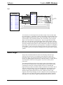
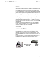
IR (Infrared)
For many years infrared remote control has been very popular, and today it remains
among the most common forms of serial control. As the name implies, infrared
control consists of serial data transmitted via pulses of infrared light. In addition, IR
signals are usually modulated by a carrier signal. In most cases this carrier signal has
a frequency of approximately 40kHz, though some can go as high as 1MHz.
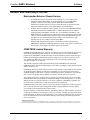
In the Crestron world there are two applications of IR control. Crestron wireless user
interfaces may use IR for communication with the control system. In this case the IR
is transmitted/received by Crestron equipment is in a proprietary format.
Crestron IR wireless interface
The other application of IR control is IR signals that the system generates to control
other manufacturer’s devices (e.g. to mimic Sony or Panasonic). The system can
generate the functions that were available on the device's remote control.
Since IR is a one-way communication, there is no feedback from the equipment
being controlled. That is, data is transmitted to the device to be controlled, but no
data is returned from the device to the control system. This means that when using
IR control, you have no true feedback from the device telling you that your
command was accepted, for example. This is one inherent disadvantage with this
type of control. Another disadvantage of IR is that it depends upon a line-of-sight
between the control system and the device to be controlled. To counter this problem,
Crestron can provide an IR probe, which provides a wired connection from the
8 • Crestron SIMPL Windows
Primer – DOC. 6253
Crestron SIMPL Windows
Software
control system to the IR receiver on the controlled device. Care must be taken to
ensure that the IR emitter on the IR probe is properly located next to the receiver.
Remote IR Equipment
Manufacturers do not normally publish the exact nature of the data that is being sent
via their IR remote controls. Therefore in order to generate the proper signal out of
the Crestron IR card, the remote must be learned through the use of a special device
called an IR Learner. The device, when attached to a PC and used in conjunction
with Crestron’s IR learning software (DEAL for Windows), will generate a driver
file that can be inserted into your programs. Once the program is finished and loaded
into the control system, the control system’s IR card can convert the information in
the driver file into the proper electrical signal.
Crestron IR Equipment
IR Probes (CNXIRP and STIRP)
The IR probe (CNXIRP or STIRP) is a very small, wired IR emitter that Crestron
developed to be installed externally over a device’s IR window. The probe is wired
from the control system and emits IR signals directly into the device's IR window.
Since the IR Probe can be mounted externally on equipment, it eliminates the need to
open other manufacturer’s equipment in order to rewire or alter the IR window. In
addition, by installing the probe directly on the device being controlled, the
interference caused by direct sunlight and high efficiency fluorescent lighting can be
eliminated.
IR Sprayer
The IR sprayer in an IR emitter that can “spray” IR signals 90 degrees. It eliminates
the need for the IR probe and can be positioned in a central location to reach all
devices. It is designed to handle several IR codes so only one sprayer is needed for
many devices.
IR Device Modules/Control Cards
IR device modules, such as the C2IR-8 or the IR ports built into some control
systems, provide control of IR or some serial controlled devices. The C2IR-8 and the
built in IR ports require the IR probe (CNXIRP) when using IR communication.
See Serial IR for information on using IR ports for serial communication.
IR Learner (CNXLIR)
Crestron Electronics CNXLIR is used to "learn" the codes (pulses of infrared light)
that a device's remote sends to control a piece of equipment. By learning these codes
programmers can create custom IR device drivers. DEAL for Windows software
allows programmers to create, modify, and test driver files. Programmers can then
store the learned .IR files in the User Database for use in their SIMPL Windows
programs.
Primer – DOC. 6253
Crestron SIMPL Windows • 9
Software
Crestron SIMPL Windows
Crestron Database
As described earlier, the Crestron Database contains hundreds of pre-coded IR driver
files for programmers to utilize. This database covers most of the IR controlled
devices on the market today. In fact, the database supports all current control
formats, including relay control, analog voltages, and TCP/IP. Programmers can
search the database by manufacturer or device type.
Custom Serial
The term custom serial is used here to describe a communications protocol that is
similar to IR, but is carried out over a wire rather than light pulses, and there is no
carrier frequency. It is called custom because currently a number of manufacturers
employ this method, but there is no true standard. Sony Control-S and Marantz RC-5
are examples of custom serial formats in use today.
In terms of usage, this form of serial communications differs from IR only in that a
specially made wired cable must be used in place of an IR probe to connect from the
control system to the controlled device. Because the data format is normally identical
to a corresponding IR remote, serial drivers are created first by learning the remote to
generate an IR driver, then by passing the file through a special filter that removes
the carrier frequency. Just like with IR, custom serial signals are generated using an
IR card such as the C2IR-8.
Crestron Custom Serial Equipment
CNSP-109
The CNS-109 is an Electrahome/Vidikron Cable for use with C2IR-8 or (1) serial
output port.
CNSP-110
The CNSP-110 is a Sony VO 5000, 7000, 9000 serial Umatic cable for use with
C2IR-8 port.
CNSP-112
The CNSP-112 is a Sony Control-S cable for use with (1) C2IR-8 port.
RS-232, RS-422, and RS-485
The terms RS-232, RS-422, and RS-485 all refer to physical standards for serial
communication developed by the Electronic Industries Association (EIA). The
standards specify the electrical interface between equipment. These standards have
been developed to allow various pieces of equipment to communicate with one
another without concern for special hardware; any device that conforms to one of the
standards above should be able to communicate with any other device conforming to
the same standard. Of the three formats, RS-232 is by far the most popular for use in
control systems. For the remainder of this section, the term RS-232 will be used to
describe any of the three protocols, except where noted.
Unlike the IR or custom serial formats, RS-232 control does not use ready-to-go
driver files. Instead, the data format, or protocol, that a controlled device is
expecting will be described in the unit's manual. This protocol includes the data that
the device expects to receive and transmit, the speed at which it communicates (baud
rate), the error checking (parity), the number of data bits and the number of stop bits.
In addition, a given device may require hardware (RTS/CTS) or software
(XON/XOFF) handshaking, which controls the flow of data between two devices.
All of these elements are adjusted in the control program to match the manufacturer's
specification.
10 • Crestron SIMPL Windows
Primer – DOC. 6253
Crestron SIMPL Windows
Software
Because of the absence of a driver file, RS-232 control is generally considered more
difficult to program than IR or custom serial. This is because each time an RS-232
device is to be programmed, the programmer must look up the protocol in the
manual, and then write the necessary logic into his program to send this data. To
counter this, many devices have dedicated modules written for them. These modules
can be plugged into a program and used to generate all the proper control codes
automatically.
The differences between RS-232, RS-422, and RS-485 are physical in nature, and do
not affect the programmer, except that they must make sure that the Crestron product
being used to send the data supports the format, and has been configured properly.
RS-232 uses one wire to transmit data, and one wire to receive it. It is generally valid
for sending data up to 50 feet, but this distance can depend on many factors, such as
cable quality, baud rate, and the ambient electrical noise. The RS-422 format uses a
balanced pair of wires for transmission, and another pair for reception. The balanced
pair allows the data to be less susceptible to noise, and RS-422 signals can be sent up
to 2000 feet. The final standard, RS-485, is similar to RS-422 except that a single
pair of conductors is used for both transmitting and receiving data. This makes RS485 very attractive for network applications, where data is being shared between
more than 2 devices. A typical application might be an HVAC system that
communicates to various thermostats and to a control system over an RS-485 LAN.
The Crestron C2IR-8 plug-in control card can only transmit RS-232 one-way. The
C2COM-2 plug-in control card is capable of generating RS-232, RS-422 or RS-485
two-way signals. The ST-COM network device can generate RS-232, RS-422, or
RS-485 two-way communication data.
Crestron RS-232, RS-422, and RS-485 Equipment
C2IR-8
The C2-IR8 includes eight serial ports for one-way RS-232.
C2COM-2
The C2COM-2 is a Cresnet plug-in control card. It includes two bi-directional RS232/RS-422 (DB-9) ports with hardware handshaking.
CAUTION: The DB9 pin-outs on the C2COM-2 control card are not standard RS232. Connecting a straight-through serial cable may damage equipment. Refer to the
Crestron Cable database or contact Crestron for serial cable pin-out specifications.
ST-COM
The ST-COM network device can generate either RS-232, RS-422, or RS-485 data.
Limitations
RS-232 is limited to a wire length of 50ft (15 m) and a minimum of three conductors
(RXD, TXD, and Ground).
Each piece of equipment requires a specific (protocol) format for the data it is
expecting.
Programmer needs to be familiar with binary, hex, and/or ASCII in order to generate
the correct strings.
MIDI (Musical Instrument Digital Interface)
MIDI stands for Musical Instrument Digital Interface and is yet another serial
communications standard. As its name implies, MIDI is used most commonly for
allowing musical instruments to talk to one another. However, certain audio mixers,
Primer – DOC. 6253
Crestron SIMPL Windows • 11
Software
Crestron SIMPL Windows
which sometimes find their way into control system applications, use MIDI control.
From a programmer’s viewpoint, MIDI does not differ from RS-232, RS-422, or RS485. From a hardware standpoint, the CNX-MIDI card is required to generate the
proper control signals.
Crestron MIDI Equipment
CNX-MIDI
The CNX-MIDI interface card is a MIDI IN, OUT and THRU interface. It is used
with mixers and lighting equipment.
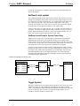
Analog Voltages
Certain devices, typically units such as camera pan-tilt heads, lighting control
systems, or voltage-controlled attenuators (VCAs) can be controlled with an analog
voltage. Programmable analog voltages can be generated using the CNXAO-8 card
or C2I-IO8. The latter card contains 8 Versiports capable of being programmed for
digital input/output or analog output.
Custom Crestron Interfaces
Certain devices have control interfaces that do not fall neatly into one control method
or category. In these instances Crestron has developed custom modules (either plugin control cards or network modules) to offer control. Examples of these include:
•
•
•
•
•
Line-level audio attenuation (volume control)
Pan/Tilt and Zoom/Focus control
Slide projector control
Keyboard/Mouse interface
Lighting (dimmed and non-dimmed) and motor control
modules
For detailed information regarding the above, see the Crestron Catalog for exact
model names, and reference the User Guide for each module.
Cresnet
The Crestron network, or Cresnet, refers to the network topology that is used by
Crestron. The RS-485 bus is used to connect the control system to Crestron
‘network’ devices such as a CNECI-4A (electric control interface for AC powered
devices) or a CNSC-1A (slide projector interface). The RS-485 bus should be used to
locate devices remotely when the limitations of IR and RS 232 restrict the
installation plans. For example, IR must have line-of-sight to the device being
controlled. Serial communications (RS-232) is limited to 50ft. The Cresnet RS-485 is
a proprietary cable connection that can be connected to devices with up to 5,000 feet
of cable.
Cresnet cable consists of:
•
•
•
12 • Crestron SIMPL Windows
Pair A #22 AWG, twisted pair with shield for data lines
Pair B #18 AWG, twisted pair for power and ground
PVC jacket
Primer – DOC. 6253
Crestron SIMPL Windows
Software
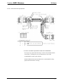
Cresnet - Network Interconnect Specifications
CAUTION: POSSIBLE EQUIPMENT DAMAGE IF MISWIRED.
Do not power up system until all wiring is verified. Care should be taken to
ensure data (Y, Z) and power (24, G) connections are not crossed.
Ground shield at control system end only.
Model CNTBLOCK network terminal block is recommended for testing
purposes and convenience of wiring.
Primer – DOC. 6253
Crestron SIMPL Windows • 13
Crestron SIMPL Windows
Software
SIMPL Windows Programming
Introduction to SIMPL
Crestron engineers are dedicated to the development of our products and the
interface with other manufacturer’s equipment. However, control systems need
individual programming in order to be customized for each installation. Crestron
control systems are programmed using SIMPL (Symbol Intensive Master
Programming Language).
SIMPL is an object oriented programming language designed for easy
implementation of your control system requirements. The objects that are used in
SIMPL are called symbols. Each symbol has a specific set of operations that it will
perform. The lines that connect symbols are called signals. The collection of SIMPL
symbols and their interconnection to one another is the program. Therefore, the
program is actually a picture created with objects (symbols) and lines (signals). This
type of picture is also referred to as a block diagram or flow diagram in other
applications. When planning an A/V installation, a block diagram indicating how all
of the system equipment is connected is essential to the installer. SIMPL allows the
programmer to develop a control program in a similar fashion. The collection of all
the symbols being used and the signals that connect them create a picture similar to a
block diagram. The development of a SIMPL program is intimately tied to the block
diagram of the A/V installation.
Symbol Categories
Writing a program in SIMPL is similar to wiring a circuit: you have to choose the
right components, and you have to wire them together properly. As just described, in
SIMPL the components are called symbols and the wires are called signals. Just like
in real-world electronics there are a multitude of symbols to choose from to
accomplish your goal, as you program more and more systems you will likely find a
subset of symbols that you use for most situations.
Symbols in SIMPL can be divided into two broad categories: device symbols and
logic symbols.
Device Symbols
Device symbols represent Crestron network control devices that can be included in a
program. They can be placed into or deleted from the program in the Configuration
Manager section of SIMPL Windows only. The Program Manager allows device
Primer – DOC. 6253
Crestron SIMPL Windows • 15
Software
Crestron SIMPL Windows
symbols to be connected, but not added or deleted. Device symbols are located in the
Device Library of the Configuration Manager.
Logic Symbols
While device symbols allow you to communicate with the outside world, logic
symbols allow you to make your program perform exactly the way you want. Logic
symbols can range from the very basic ones such as the AND, OR, or NOT symbols,
to those designed for very special applications. A more in-depth discussion of logic
symbols can be found in the Programming with Symbols section.
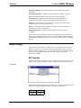
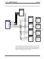
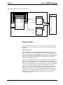
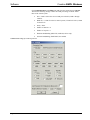
Symbol Properties
Although each symbol serves a special purpose, all symbols share some basic
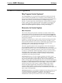
properties. These are inputs, outputs, and parameters.
Example: Analog Ramp symbol
Inputs
Symbol inputs allow signals to be connected from other parts of the program.
Depending upon the symbol type, the current state of the input signal(s) may affect
one or more output signal(s). Some symbols have a fixed number of inputs, while
others can have a variable number of inputs, determined by the programmer based
upon need.
Outputs
Except for a few special cases, the ultimate purpose of a symbol is to modify the
states of its outputs. These outputs states will depend upon the symbol type, the
current or past states of the input signals, and the values of the parameters. Because
the symbol alone determines the states of its output signal(s), the symbol is
considered the driving source for the output signals. Depending on the nature of
signal, some outputs can have more than one driving source.
Similar to symbol inputs, the number of symbol outputs is fixed for some symbols,
or can be variable based on need for other symbols.
Parameters
Some symbols also have parameters, which are constant values that help determine
how the symbol behaves. For example, a symbol that delays an action for a specified
period of time would have a parameter determining how long the delay should be
for. The exact function of a parameter depends solely on the symbol type itself.
16 • Crestron SIMPL Windows
Primer – DOC. 6253
Crestron SIMPL Windows
Software
For convenience, parameters may be expressed in a variety of formats (all of which
are directly related to one another). Although a parameter will default to one format
based upon the symbol type, you can alter the format by changing the format
specifier at the end of the value.
Listed below are the valid formats, where the character in parentheses represents the
format identifier.
•
(d)ecimal
•
(h)exadecimal
•
(%) percentage of 65535
•
(s)econds
•
(t)icks – 1 tick = 1/100 seconds (2-Series); or 1/112.5 seconds (X-Series)
•
(')character(') (single byte)
To set a parameter to a specific format, add the identifier after the value, i.e., 25%; if
the parameter is a single byte, place single quotes before and after the ASCII
character.
Parameters can also specify the time of day. Here the time of day is expressed in
military time followed by the “seconds” format specifier, as follows:
•
HH.MM.SS.HSs
•
MM.SS.HSs
•
SS.HSs
•
SSs
•
.HSs
Where HH = hours; MM = minutes; SS = seconds; and HS = hundredths of a second.
For example, the parameter 20.03.05s signifies a time value of 20 minutes, 3
seconds, and 5 hundredths of a second. When using this notation you can leave out
the larger units if you are not using them, thus "3.00.00s" would mean 3 minutes, 0
seconds, and 0 hundredths of a second (it would NOT mean 3 hours).
Depending on the function of a symbol, a parameter can be signed or unsigned.
Signed values range from–32768 to +32767; unsigned values range from 0 to 65535.
Percentages can also be expressed as negatives, i.e., -25% = 25% of 65536, or
16384. (-16384 = 49152d). Thus a parameter of -25% is the same as 49152d. Refer
to the SIMPL Windows help file for further information on valid parameter values.
NOTE: Parameters are constants whose value must be known at compile time. The
value of the parameter cannot be changed while the program is running (e.g. a signal
cannot be assigned to a parameter). To change a parameter, the program must be
changed and recompiled.
Signal Types
The concept of the signal has already been broached. Signals are the elements used
in your program to interconnect the various device and logic symbols that comprise
your program. However the discussion of signals does not end there. For starters,
signals can be one of three types: digital, analog, or serial. For any given signal, the
signal type is determined by the driving source. If the symbol that drives the signal
Primer – DOC. 6253
Crestron SIMPL Windows • 17
Software
Crestron SIMPL Windows
has an analog output, then the signal connected there will by definition become an
analog signal. The three signal types are defined in more detail below:
Digital Signals
Digital signals are the most common in the SIMPL language, and a typical program
will be comprised of between 95% and 100% digital signals. This type of signal can
have only two states, often referred to as on/off. Other common descriptors are
high/low, active/inactive, or 1/0. This transition is called the rising edge, or positive
edge. Generally speaking, actions in SIMPL program are triggered by a digital signal
going from the low to the high state. Although most actions are edge-triggered,
others can be level-triggered (based upon current state, not just last transition). For
example, a Toggle symbol is edge-triggered; it drives its digital output high and low
with each rising edge of its input. In contrast, the Buffer symbol is level-triggered; its
‘enable’ digital input signal must remain high for signals to flow.
When looking through the symbol library reference, take note as to which symbols
are edge-triggered, and which are level-triggered. You can find this information by
selecting the symbol and pressing F1, which will open the context-sensitive help
window for the symbol.
As stated previously, the type of signal is determined by its driving source. In many
applications there are signals that have multiple driving sources. Such signals are
said to be jammed. As a general rule, digital signals should not be jammed; that is,
they should have only one driving source. But there are two important and common
exceptions: system inputs (such as button presses), and the outputs of Buffer
symbols. These exceptions can be very useful in applications where functionality
must be shared across several user interfaces. For example, a DVD player can be
controlled by a touchpanel as well as by a remote control transmitter.
In SIMPL Windows, digital signals are represented by a blue line.
Analog Signals
Analog signals are represented with 16-bit numbers, and thus can have values
between 0 and 65535 (216 - 1). This means that unlike digital signals, analog signals
can vary continuously in value, in the same manner as a parameter such as volume or
temperature. This property makes analog signals useful for controlling devices that
do not have discrete on/off settings, such as volume controllers, pan/tilt head
controllers, and lighting dimmers.
Unlike digital signals, analog signals by their very nature may have multiple driving
sources. Thus analog signals are said to be jammable. In practice, whenever more
than one symbol is driving the same analog signal, the symbol that lasts changes the
signal's value takes precedence. Typical applications for analog signals are volume,
lighting, and temperature levels, as well as advanced string manipulation.
In SIMPL Windows, analog signals are represented by a red line.
Serial Signals
Serial signals facilitate the transmission of serial data (i.e. strings of characters).
These signals can be generated by incoming data on a COM port or by a symbol that
has a serial output. Similar to analog signals, serial signals are jammable; thus
multiple symbols can be used to generate strings on a single signal. By default, serial
signals are transient, meaning that the data on a serial signal is only valid for the
logic wave in which it was created (logic waves are described below). Symbols such
as the Make String Permanent symbol allow serial strings to be retained in memory.
In SIMPL Windows, serial signals are represented by a black line.
18 • Crestron SIMPL Windows
Primer – DOC. 6253
Crestron SIMPL Windows
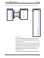
Software
Example Signal Colors
Some signals are ambiguous, meaning that the signal type is determined by the
driving source. For example, the inputs and outputs of a Serial Buffer symbol can be
either serial or analog. The ambiguous signal is resolved when the signal is
connected to an analog or serial symbol. Ambiguous signals should be resolved
before the program is finalized; otherwise a compiler error will be generated.
In SIMPL Windows, ambiguous signals are represented by a green line. Once they
are resolved, the line color changes to blue (digital), red (analog) or black (serial).
Special Signals ‘0’ and ‘1’
The special signals ‘0’ and ‘1’ are used to force a value on a signal. ‘1’ is a digitalonly signal whose value is always logic high. A digital signal named ‘0’ will always
be logic low. A ‘0’ on an analog signal forces the signal to a constant value of zero.
On a serial signal, a ‘0’ will result in no string being transmitted.
Logic Waves and Logic Solutions
A logic wave is a processor unit of measurement defined as the elapsed time
between the moment a signal's state changes and the moment that all symbols
connected to that signal have been evaluated. This is analogous to the term
"propagation delay" used when describing digital hardware. Although logic waves
are not expressed in real-world time units (i.e., milliseconds) due to the fact that the
actual time is indeterminate at compile time, SIMPL guarantees that all symbols
have a propagation delay of exactly one logic wave.
Note that some symbols do not always conform to this rule. Examples are time-based
symbols such as Delay and One-Shot. While the propagation delay of the Delay
symbol is determined solely by its parameter values, a One-Shot will propagate in a
single logic wave when its trigger input goes high. However, the falling edge of the
input has no effect, and the symbol's output will go low only after the specified time
has expired.
One or more logic waves make up a logic solution.
A logic solution is defined as the time it takes, starting with an external impetus, for
the SIMPL logic processor to evaluate all symbols to the point at which all signals in
the program have reached a "steady state" that is, the time required for all signals to
settle to stable, unchanging states. The length of a logic solution can vary at runtime,
and can be expressed in logic waves, i.e., "when this button is pressed, the
subsequent logic solution should take 6 logic waves".
It is important to realize that time-based (scheduled) events do not occur during a
logic solution, except to serve as the impetus to initiate one. Thus using an Oscillator
symbol would not cause an endless logic solution. Instead, each time the output
signal of the Oscillator changes, it triggers a new logic solution that runs until all
affected signals arrive at their final states. On the other hand, endless logic solutions
can be created by connecting logic incorrectly (i.e., routing the output of a NOR
symbol back into its input). This situation should obviously be avoided.
Primer – DOC. 6253
Crestron SIMPL Windows • 19
Software
Crestron SIMPL Windows
Programming with User Interfaces
The heart of any well-designed control system is the user-interface. This is the link
between the end-user and the control system itself. Regardless of how cleverly
programmed, or technically savvy a given system is, if it lacks a quality userinterface it is unlikely that the system will be appreciated, or used to its full potential.
Crestron control systems offer an impressive array of user interface options, from the
top-of-the-line Isys TPS touchpanels, to cost-effective and simple wired button
panels. No matter what type of interface(s) you are using in your system, this section
will help explain how to use them in your program.
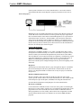
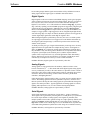
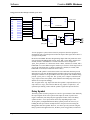
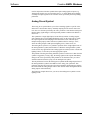
Button Presses
In a program button presses (whether from a touchpanel, wired or wireless button
panel, or other interface) are associated with signals. Since for a given device not all
buttons may be used, unused buttons are not given signal names. When a button is
pressed, the corresponding signal is asserted in the control system program. When
the button is released, that same signal is de-asserted. See the signal-state diagram
below for a graphical representation of this.
Simplified Button-Press
Note that in this case the button alone determines the state of the signal. That is,
when the button is pressed, the signal is high, and when the button is not pressed, the
signal is low. Because of this the button is the driving source for that signal. Since a
button can have only two states, high or low, the signal that it drives can only have
two states, thus this signal is a digital signal.
In most cases digital signals are limited to one driving source. That is, it is illegal to
have two different symbols driving the same digital signal. However, there are two
important exceptions to this rule. One concerns the Buffer symbol, which will be
described later. Button presses are another exception, in that a single signal may be
driven from multiple buttons. This can be very convenient, especially in cases where
you want to share functionality across several user interfaces. For example, the same
volume up and volume down controls may be accessible from a touchpanel as well
as from a wireless remote. Instead of having to create different signal names for each
case, and then using an OR symbol to combine the functionality, it is legal (and
desirable) to use the same signal names in both cases.
20 • Crestron SIMPL Windows
Primer – DOC. 6253
Crestron SIMPL Windows
Software
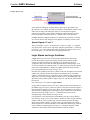
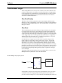
Button Feedback
User-interfaces that support 2-way communication (any interface except for 1-way
wireless transmitters) also support button feedback. This term is used to describe the
button's active appearance. For button panels, feedback is usually indicated with a
LED located inside the button housing. For touchpanels, feedback can vary, and
often includes changing the frame and text color, along with a simulated 3D
appearance.
Visual Button Feedback
Feedback is vitally important to a good user interface design. For one thing, feedback
lets the user know that a button press has registered with the system. This is
especially important for touchpanels, where the user cannot tell from feel alone
whether they pressed in the right spot. Another purpose feedback serves is to provide
information to the user about the current state of the system (that the VCR is
currently in PLAY mode, for example). In this case, care should be taken to make
the feedback be as accurate as possible, as inaccurate or vague feedback will only
serve to confuse the user.
Whether a button is pressed or not is determined by the user (or the user's finger to
be exact!) but it is a signal that decides whether a button is shown in its feedback
state or not. Therefore, the signal is the driving force for the button feedback. Where
the signal comes from depends upon what type of feedback is needed. The most
basic type of feedback is called momentary feedback. Momentary feedback causes
the button to display in its feedback state only when the button itself is pressed. This
type of feedback makes sense for functions that occur only while the button is
pressed. For example, volume up and volume down buttons typically receive
momentary feedback because the volume level only changes (goes up or down)
while the corresponding button is pressed.
Momentary feedback can be achieved simply by connecting the button press signal
name to the feedback signal for the same button, as shown in the diagram below.
Volume Momentary Feedback
Primer – DOC. 6253
Crestron SIMPL Windows • 21
Software
Crestron SIMPL Windows
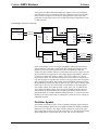
Certain buttons may call for more complex feedback. For example, a volume mute
button may alternately turn the mute on and off. To indicate this with feedback, the
button should display in the feedback state when the mute function is on, and turn off
when mute turns off. Clearly, momentary feedback will not do the trick here, so we
must use logic symbols to generate the desired behavior. This example shows how to
do this using the Toggle symbol.
Volume Mute – Toggle Feedback
An even more elaborate form of feedback is possible when there is 2-way
communications between the control system and a device being controlled. In this
case it is sometimes possible (and desirable) to show feedback based solely upon
information received from the device (NOTE: this information is also called
feedback. Don't confuse this with button feedback). For example, suppose you are
controlling a switcher, which allows you to choose one of 4 video sources. If the
switcher itself sent information back to the control system detailing which source
was currently selected, your program could use that information to highlight the
button representing the selected source. This would guarantee that the feedback was
always correct, even if a user performed the switch from the switcher itself, and not
via the control system.
Subpages (touchpanels only)
Subpages are powerful objects available for touchpanels only. Subpages are in many
ways similar to standard touchpanel pages, in that they may contain buttons, text,
graphics, etc. However, subpages ordinarily do not take up the entire display screen
area. Instead, a subpage often defines a small area with buttons serving a specific
function, such as VCR control buttons. A given subpage can then be designed to
22 • Crestron SIMPL Windows
Primer – DOC. 6253
Crestron SIMPL Windows
Software
appear on top of a standard page at any time and then disappear when no longer
needed, similar to a dialog box in Windows or Macintosh computers.
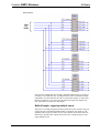
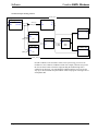
In order to make the implementation of subpages as flexible as possible, they are
controlled (i.e. shown or hidden) via touchpanel feedback signals. That is, whenever
a subpage is needed, a subpage reference is created at the exact location where it is to
appear. This subpage reference is simply a link to the subpage object that was
created previously. Each subpage reference is then be assigned a join number, and
the feedback signal for that join number will determine whether or not the subpage
appears. As long as the signal is high, the subpage will appear, and will disappear as
soon as the signal goes low. The example below shows the logic necessary to control
a volume subpage from a single button, allowing the subpage to be toggled on or off
as necessary.
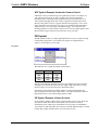
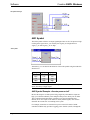
Analog displays (touchpanels only)
VisionTools Pro-e provides a number of objects for different types of analog
displays. For example, if you want to create a bargraph, you can go to the
VisionTools Pro-e toolbar, select the Gauge (bargraph) object and scale it to the size
you want. You would then assign an analog feedback join number to the gauge that
represents the analog channel that the gauge will display the value of.
VisionTools Pro-e provides several analog objects:
1.
Gauges (bargraphs)
2.
Sliders (bargraphs that also can be moved via touch)
3.
Digital gauges (display an analog signal in number format)
4.
Percentages (display analog signals in %)
5.
Time (display analog signals in time format: HH:MM:SS)
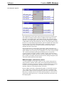
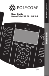
Indirect text (touchpanels only)
Indirect text is a feature where the particular text string that appears on a touchpanel
button can change, depending on the signal state. For example, when the user
touches a button it might read “Power ON”, and when touched again it might read
“Power OFF”.
In SIMPL Windows, touchpanel definitions have built-in serial feedback signals for
defined for indirect text fields. These text fields accept serial data signals directly.
Serial Send to touchpanel text fields
Primer – DOC. 6253
Crestron SIMPL Windows • 23
Software
Crestron SIMPL Windows
Building a Program with SIMPL Windows
Programming Process
Identify the equipment that is going to be controlled.
Programmers should prepare documentation that lists all the equipment that is to be
controlled.
Determine how the equipment is going to be controlled.
Knowing how the various pieces of equipment are going to be controlled is very
important. This will let the programmer know what control devices (Network
Module, Control Card, or other) will be necessary to control the equipment.
For example: IR control devices require a C2-IR8 plug-in card.
Configure the system in SIMPL Windows
Configure the system by building it in the Configuration Manager. Locate the control
system in the Device Library. Drag and drop the control system into the System
Views window. Complete the system configuration by adding interfaces, network
modules, control cards, and other devices. All the necessary Crestron hardware
should be included in your configuration.
Program the system in SIMPL Windows
After the system is built by adding all the necessary Crestron hardware, begin
programming the system by working in the Programming Manager. Program each
button function from touchpanels and other user interfaces. Begin by naming the
output signals from the user interface. Select the symbol(s) needed for the program
in the Symbol Library. Drag and drop the symbols into the Program View window.
Assign signal names to symbol inputs and outputs in the Detail View window.
Basic Programming Rules
1.
Symbols can be either device symbols or logic symbols.
2.
Logic symbols perform an operation that manipulates signals.
3.
Logic symbols only change states of output signals.
4.
Signals connect symbols.
5.
Digital signals should have only one driving source. Only one symbol in the
program should list the signal as an output.
NOTE: There are some exceptions to digital signals having only one driving source.
The exceptions are button presses and buffer outputs.
Build a System
The SIMPL Windows Configuration Manager allows you to do the following:
24 • Crestron SIMPL Windows
•
Select the control system.
•
Select additional Crestron hardware required for the installation. This can
include plug-in control cards, network control modules, touchpanels, and
wireless remotes.
Primer – DOC. 6253
Crestron SIMPL Windows
Software
•
Select user devices made by third-party manufacturers. These are usually
the devices being controlled and can include CD players, DVD players, TVs
and any other equipment the end user interfaces with using the control
system.
•
Configure the devices by specifying which units are connected to which
control cards or network modules. Assign ports, network addresses and IP
information, specify communication settings and document the system with
connection/installation notes.
•
Specify what VisionTools Pro-e projects are required for the system.
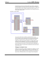
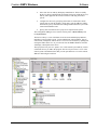
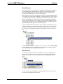
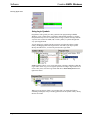
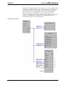
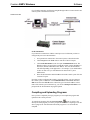
The Configuration Manager screen consists of three panes: a Device Library and
two System Views.
The Device Library is a tree with folders for all Crestron and third-party hardware,
including Crestron control systems, Cresnet and Ethernet control modules, plug-in
control cards, touchpanels, and user devices. You can view hardware by opening and
closing the folders in the tree. As you select devices the SIMPL Windows status bar
will display a description of the device.
The top System View pane is a "picture view" of the control system and any Cresnet
or Ethernet devices you add to the program. The lower System View is a tree of the
control system with numbered slots that you can open and close to view the network
addresses and configure each item.
Primer – DOC. 6253
Crestron SIMPL Windows • 25
Software
Crestron SIMPL Windows
Control Systems
The first step in building a system with SIMPL Windows is to select the control
processor. The Device Library includes all current Cresnet and Ethernet control
systems, including 2-Series, QM, and X-Series models.
You can quickly add a control system by double-clicking the empty folder that is
displayed in the lower System View and selecting the control system from the list.
You can also the drag the control system to either of the System Views.
26 • Crestron SIMPL Windows
Primer – DOC. 6253
Crestron SIMPL Windows
Software
Another method is to right-click the control system in the Device Library and choose
Add Device to System from the submenu.
Network Hardware
Once you add the control system, the next step is to add the other devices that
comprise the system, including network control modules, touchpanels and other
interfaces, additional plug-in cards, and user devices from the Crestron Databases.
The quickest and most efficient way to add Crestron hardware is to double-click the
card slot or Network ID in the tree view. This will open a selection list of Crestron
devices that are compatible with that slot. For example, if you want to add a Cresnet
device you can double-click the Net Device slot. Then scroll down the list to locate
the device.
To quickly add multiple copies of a Crestron device, right-click the unit in the
Device Library and select Add multiple copies from the submenu. Then enter the
number of devices you want to add and click OK.
Primer – DOC. 6253
Crestron SIMPL Windows • 27
Software
Crestron SIMPL Windows
If you add a Crestron device to a control card slot, SIMPL Windows will auto-assign
the network address, first by the default factory ID and then sequentially.
To add a Crestron device to a specific network address expand the slot and doubleclick the network address. This will open the device selection list and add the device
to the selected ID.
Another way to open the device selection list is to right-click the slot or network
address and select Add item from the submenu.
Plug-in Control Cards
Crestron plug-in control cards are circuit boards that can be easily installed in the
expansion slots of the control system. Plug-in cards serve many purposes, from
providing additional ports for IR or serial control, to adding audio mixing
capabilities to a processor, to connecting the control system to the Ethernet network.
You can select cards from the Plug-in Control Cards folder of the Device Library.
You can quickly determine which plug-in cards are compatible with which slots by
double-clicking the empty card slot in the control system tree. This will display a list
of all available cards.
28 • Crestron SIMPL Windows
Primer – DOC. 6253
Crestron SIMPL Windows
Software
Serial Devices
Crestron processors control serial devices using physical standards such as RS-232,
RS-422, and RS-485. Unlike IR, RS-232 control does not use ready-to-go driver
files. Instead, the data format, or protocol, that the device is expecting will be
provided by the manufacturer in the unit's documentation.
Most Crestron control systems provide built-in COM cards and IR cards that enable
1-way and 2-way serial control. In addition, Crestron manufactures a variety of plugin COM cards, plug-in IR cards, and standalone network devices that enable serial
control. For example, the C2COM-2 plug-in control card is capable of generating
RS-232, RS-422 or RS-485 two-way signals. The ST-COM is a standalone Cresnet
device that also generates two-way communication data. The C2-IR8 card provides
eight IR/serial ports that support one-way RS-232 signals.
Crestron's COM cards have internal serial drivers ready to be configured for 2-way
communication. Once you know the protocol for a serial device you can "add" the
device by configuring the communication settings of the serial driver. You can view
the serial ports by expanding the COM card or COM device in the control system
tree.
Double-click the serial driver to display its Device Settings. Click the Serial Settings
tab and configure the device according to the manufacturer's specification. This is
described in detail in the Configure Device section.
User Devices
You can locate third-party user devices in the Device Library by Manufacturer or
Device Type. To add a user device, right-click the unit and select Add device to
system. As shown below, you also have the option to add multiple copies of the
device.
You can also use the standard Windows drag-and-drop method to drag a device to
the card slot or port address in the tree view.
Primer – DOC. 6253
Crestron SIMPL Windows • 29
Software
Crestron SIMPL Windows
To hide unused slots from the tree view, right-click any item in the tree and select
Hide Unused from the submenu. This will make only the connected network
addresses visible and simplify the tree view.
Network IDs
A Network ID is a two-digit hexadecimal value that uniquely identifies each
Crestron device on the control system network. Every programmable Crestron
device, including network control modules, remote processors, touchpanels, remotes
and Ethernet devices, must be assigned a unique network address to enable
communication with the control system. The type of ID a device is assigned depends
on the communication format.
Cresnet devices receive a Cresnet ID, also called a NET ID. The control system's
Net-Device slot in SIMPL Windows provides 252 NET IDs for connecting Cresnet
devices, although the physical network would require the use of a network expander
if more than 30 Cresnet devices are connected. NET IDs range from 03 to FE.
Ethernet devices receive an IP ID, in addition to a unique IP address or host name.
The Ethernet card slot in SIMPL Windows provides 252 IP IDs for connecting
Ethernet devices. IP IDs range from 03 to FE.
Wireless panels and remotes must communicate with a Cresnet gateway receiver and
are assigned an IR ID or RF ID. The number of available IDs differs depending on
the gateway. Crestron's two-way wireless gateways such as the CNRFGWX provide
15 RF IDs (01 to 0F) for connecting wireless panels. Other gateways, such as the
CNIRGW, provide up to 254 IR IDs (01 to FF).
The Network ID you assign to a device in SIMPL Windows must be the same as the
device's hardware ID, which is the internal ID set at the factory. You generally have
to change the hardware IDs of Crestron devices so that they match the IDs assigned
in the software. The procedure for changing the hardware ID differs depending on
the device, and is described in each unit's documentation.
You can set or change the assigned Network ID of a Crestron device when you add it
your program. You can drop a device directly on a network address. You can also
drag the device from one network address to another.
Finally, you can edit the Network ID of a device when you double-click it to open its
Device Settings. This is described in the next section.
Configure Devices
Once you have added all your Crestron and third-party hardware to your system, you
can configure these network devices by double-clicking the device in either of the
System Views. You can also right-click the device and select Configure. This will
display the Device Settings dialog box. The available configuration options differ
depending on the device.
Cresnet Devices
Device Name: You can use this tab to change the default name of the device and
enter a device location. The new name will appear in the System Views and Program
30 • Crestron SIMPL Windows
Primer – DOC. 6253
Crestron SIMPL Windows
Software
View, as well as in the title bar of the device's symbol. The device name and location
will be included in the Device by Location report. It's a good idea to provide
descriptive names and specific locations for all network devices, as this can aid in
debugging. Devices that draw power from the Cresnet network will also display the
power consumption in watts.
Net ID: You can change the Cresnet ID of the device by selecting from the list.
Connection Sheet: You can use these free text fields to enter information and
program notes about connected equipment, installation requirements, functionality,
and other points you want to document. This information will be included in SIMPL
Windows reports such as the Connection Sheet, Devices by Location, or any User
Report that you generate.
Primer – DOC. 6253
Crestron SIMPL Windows • 31
Software
Crestron SIMPL Windows
Device Info: This tab provides "read-only" program information about each device.
Ethernet Devices
IP Net Address: You can change the IP ID of an Ethernet device or Ethernet remote
processor by selecting from the list. In addition to the IP ID, you have to assign a
unique IP address. If the device or remote processor has a static IP address, click Use
IP Address and enter the IP address in the text fields.
If the device or remote processor is enabled for DHCP or else has been assigned a
host name by the system administrator, then click Use Host Name and enter the fully
qualified domain name.
32 • Crestron SIMPL Windows
Primer – DOC. 6253
Crestron SIMPL Windows
Software
Serial Devices
Serial Settings: Set the device's serial protocol according to the manufacturer's
specification. The protocol you set here includes the communication standard (e.g.,
RS-232), the speed of data transmission (baud rate), error checking (parity), the
number of data bits, and the number of stop bits. In addition, a given device may
require hardware (RTS/CTS) or software (XON/XOFF) handshaking, which controls
the flow of data between two devices. Finally, some devices require line pacing, or
pauses between characters during transmission.
Touchpanels
UI Project: Each touchpanel in a SIMPL Windows program has an associated
VisionTools Pro-e project that defines join numbers for every digital, analog, and
serial signal that the touchpanel sends to the control system or receives as feedback.
You have to map the joins in the VT Pro-e touchpanel project to input and output
signals on the touchpanel symbol detail. To facilitate this you can import the
touchpanel project into SIMPL Windows. The imported project will be included if
you create an archive.
To import the touchpanel project click Browse to locate the project file. You can
select the Create signals check box to automatically define digital and analog
signals on the touchpanel definition. Here serial joins, sound joins, Web control and
analog state joins will NOT be imported and will need to be defined manually.
Signal names will have the format: Page name_button text. Note that this operation
will not overwrite or erase existing signals on the touchpanel symbol.
Chaining: (Cresnet only): If you have multiple touchpanels of the same type that
will be used for exactly the same functions, you can chain them together so that they
will be programmed identically. Here the Chain Master is the touchpanel that
determines the characteristics of the rest of the chain. To chain a touchpanel to a
Chain Master, select the Net ID of the Chain Master from the drop-down list. In the
example below, the touchpanel will be chained to the Chain Master located at Net ID
Primer – DOC. 6253
Crestron SIMPL Windows • 33
Software
Crestron SIMPL Windows
04. The chained device will share the master device's definition, and it will be
displayed in the top System View as a Chained
icon.
The Chain Master panel will automatically display the Net IDs of all touchpanels
that have been chained to it. In the following example, the Chain Master has two
chained touchpanels located at Net IDs 03 and 05. As indicated below, the chained
panel will lose any signals that were previously defined.
Connecting Signals
After you build the system by adding all the necessary Crestron hardware in
Configuration Manager, begin programming the system by working in the
Programming Manager. Program each button function from the system touchpanels
or other user interface devices. Begin by naming the output signals from the user
interface (output signals will already have assigned names if a VT Pro-e project has
been brought in when configuring a touchpanel in Configuration Manager).
Select the symbol(s) needed for the program in the Symbol Library. Drag and drop
the symbols into the Program View window. Assign signal names to symbol inputs
and outputs in the Detail View window.
Define Signals from User Interface
User interfaces are usually the most convenient place to begin programming. In a
program, button presses (whether from a touchpanel, wired or wireless button panel,
keypad, or other interface) are associated with signals. When a button is pressed, the
corresponding signal name is asserted in the control system program. When the
button is released, that same signal is un-asserted.
34 • Crestron SIMPL Windows
Primer – DOC. 6253
Crestron SIMPL Windows
Software
The button press is the end user’s request for a specific action; therefore, the output
signals of the user interface have to be named, or “defined”. This way, each signal
can be identified and routed properly.
To program a user interface, locate it in Program View by expanding the appropriate
slot or folder. Then drag the interface to Detail View or double-click it. This will
display the touchpanel definition in Detail View.
User Interface (Touchpanel) Symbol
Click each signal you want to name. Signals should be given descriptive names such
as “Power_On”, “Screen_Up” or “DVD_Play”, for example.
Selected Signal
The signal must be selected or highlighted before text can be entered. By default, the
top input signal (top left) is automatically selected when a signal is first displayed.
Use the pointer or arrow keys to navigate around the symbol.
NOTE: Signals whose symbol label appears in [brackets] are optional and are not
necessary for the symbol to operate.
You can enter the signal name when the signal is highlighted.
Primer – DOC. 6253
Crestron SIMPL Windows • 35
Software
Crestron SIMPL Windows
Entering Signal Name
Using Logic Symbols
Programmers will typically use many symbols when programming in SIMPL
Windows. Logic symbols allow programmers independent flexibility by offering
many different ways to solve a control problem. Logic symbols can range from the
very basic ones such as the AND, OR, or NOT symbols, to symbols designed for
very special applications.
You can bring logic symbols into the program by selecting them in the Symbol
Library and dragging them into Program View. Note that if you drop a symbol
directly into Detail View, it will not be placed in the Logic folder.
SIMPL Windows allows you to create Subsystems, which are subfolders within the
Logic folder. In this way you can organize symbols according to logic functions. To
create a subsystem, select the Logic folder and choose Insert Subsystem from the
right mouse menu.
When you create the new folder, you can right-click it to rename the folder to
something meaningful, and you can drag symbols from the Symbol Library directly
into the new folder.
36 • Crestron SIMPL Windows
Primer – DOC. 6253
Crestron SIMPL Windows
Software
Programming with Logic Symbols
Introduction
In the last chapter we saw how a program could be written simply using device
symbols and connecting them via signals. This type of program uses "direct
functionality." That is, button presses (or any other type of system input) are
connected directly to control functions, such as the PLAY command on an IR driver.
When the button is pressed, the PLAY command is sent out the IR port, and it stops
as soon as the button is released. This type of programming is simple, but as control
systems get more complex, you will find that you require more control over what
goes on inside the program. This is handled through the use of logic symbols.
In general terms each logic symbol can be thought of as a very specialized processor.
A logic symbol will evaluate the state of the signals connected to its input terminals,
and generate appropriate signal values onto the signals connected to its output
terminals. The values of the output signals will depend on the nature of the logic
symbol itself, and on the values of the symbol's parameters, where appropriate.
Types of Logic Symbols
Currently there are over one hundred logic symbols available for use by SIMPL
programmers. These symbols range from simple digital logic gates to complex serial
data generators. In order to make it easier to find the symbol or symbols needed for a
particular application, the entire logic symbol collection has been categorized as
follows:
Analog Operations – Symbols that are used to perform analog functions such as
ramping operations for lighting or volume presets.
Conditional – Logic gates that assert their outputs depending on whether some
condition is true or false.
Counters – Binary and decimal counters.
Debugging – Symbols that track signals during run time, or force signals to analog,
digital or serial types.
Device Interface – Mouse and keyboard simulators.
e-Control Software – Symbols that are used by Crestron e-mail power applications.
Memory – Symbols that write and read to NVRAM. That is, they retain data in
memory even if power is shut off.
Primer – DOC. 6253
Crestron SIMPL Windows • 37
Software
Crestron SIMPL Windows
Program Formatting – Symbols that help to organize and arrange program
information.
Sequencing Operations – Symbols that assert outputs according to a sequence.
Serial – Symbols that generate, parse, and process serial string data.
System Control – Symbols that affect the logic processor and allow it to
communicate with remote systems and send data directly to the console.
Time/Date – Symbols that process timing data, including astronomical clocks,
calendars, and the processor’s internal clock.
Timers – Symbols that remember their previous states and trigger functions at
specified times or after specified delays.
Touchpanel Interface – Symbols for broadcasting serial data to network
touchpanels.
The rest of this section will show examples incorporating the most commonly used
symbols. After reading this section, you can refer to the SIMPL Windows help file,
which includes individual help topics for every logic symbol available in the SIMPL
language.
Basic Logic
The term basic logic is used here to describe the most elemental logic elements in
SIMPL. If you have some experience working with digital logic, then you will be
familiar with these symbols. Even if you do not have any prior knowledge of digital
logic, this section should teach you all you will need to know to program
successfully in SIMPL.
NOT Symbol
The NOT symbol, also known as an inverter, simply inverts the input signal onto the
output. That is, whenever the input is high, the output will be low, and vice-versa.
NOT Symbol
Instead of describing the symbol's operation this way, we can use a truth table, which
shows the logical relationship between the symbol inputs and outputs.
Signal_In
Low
High
38 • Crestron SIMPL Windows
Signal_Out
High
Low
Primer – DOC. 6253
Crestron SIMPL Windows
Software
NOT Symbol Example: Automatic Camera Control
Sometimes a device provides the opposite signal than you want. For example, say
your control system is set up to receive contact closures from an automatic
microphone mixer, indicating which microphone has just been spoken into. In a
video conferencing application, these closures might be used to point the camera
directly at the speaker. However, suppose that instead of supplying a closure each
time a microphone was spoken into, the relays were normally all closed and that it
supplied an open contact to signify a microphone trigger. You could pass each
incoming signal into a NOT symbol to first invert its level. The output signals could
then be used to trigger camera presets somewhere else in your logic.
OR Symbol
The OR symbol will drive its output signal high whenever any of its inputs are high.
Looking at the figure below, you could say that 'signal_out' is high whenever
'signal_1_in' OR 'signal_2_in' are high.
OR Symbol
The truth table for a 2-input OR symbol is shown below.
Signal_In 1
Low
High
Low
High
Signal_In 2
Low
Low
High
High
Signal_Out
Low
High
High
High
Note from the truth table that when both of the input signals are high, the output is
still high. If you need an operation where the output is high when only one of the
inputs are high; you can use an Exclusive OR (XOR) symbol.
Note that the OR symbol has an arbitrary number of inputs (determined by the
specific application), and a single output. That is, a 20-input OR symbol will have a
high output whenever any of the 20 input signals are high.
OR Symbol Example: Volume Un-mute
As an example, consider volume control, which typically consists of up, down, and
mute buttons. When the audio has been muted, you may want to un-mute it
automatically if the volume up or down buttons were pressed. To accomplish this
you could use an OR symbol like the one shown. Note that additional logic is needed
to finish this example, and this will be covered in a later section.
Primer – DOC. 6253
Crestron SIMPL Windows • 39
Software
Crestron SIMPL Windows
OR Symbol Example
AND Symbol
The AND symbol will drive its output signal high whenever all of its inputs are high.
Looking at the figure below, you could say that 'signal_out' is high whenever
'signal_1_in' AND 'signal_2_in' are high.
AND Symbol
Alternatively, we can describe the behavior of the AND symbol using the truth table
shown below.
Signal_In 1
Low
High
Low
High
Signal_In 2
Low
Low
High
High
Signal_Out
Low
Low
Low
High
NOTE: Similar to the OR symbol, the AND symbol can have arbitrary number of
inputs, but always a single output.
AND Symbol Example: discrete power on/off
Because the output to an AND symbol will go high only when all of its inputs are
high, you would not ordinarily route multiple button presses directly into an AND.
This would mean that both buttons would have to be pressed simultaneously.
Instead, one or more inputs to the AND are usually latched signals, often used to
determine the current state of something in the system.
For example, assume that we want discreet power on and off control of an IRcontrolled VCR that only provides a toggling power function (on/off). Through the
40 • Crestron SIMPL Windows
Primer – DOC. 6253
Crestron SIMPL Windows
Software
use of a current sensing device, we have generated a digital signal that represents
whether a VCR is currently turned on or not. That is, when the signal ‘vcr_is_on’ is
high, the VCR is on. Using AND symbols, we can ensure that when the VCR is on,
and the ‘vcr_power_off’ button is pressed, we send the power command to the VCR.
If the VCR is off and the ‘power_off’ button is pressed, we do not want to send the
power command because this would cause the VCR to turn on. We use similar logic
to handle the case where the ‘vcr_power_on’ button is pressed. See the AND
Example for a logic diagram of a complete current sensing program.
AND Example
Buffer Symbol
The Buffer symbol can be thought of as a gate that can be opened or closed, thus
controlling the flow of data. When the gate is open, digital signals are allowed to
flow unaltered from the inputs to the corresponding outputs. When the gate is closed,
all output signals are set to logic low and the input signals have no effect on them.
Opening and closing the ‘gate’ is handled by the enable input terminal. When the
signal connected to this terminal is high, the Buffer is enabled (the gate is open), and
when this signal is low, the symbol is disabled (the gate is closed).
Primer – DOC. 6253
Crestron SIMPL Windows • 41
Software
Crestron SIMPL Windows
BUFFER Symbol- High/Low
This symbol differs from the other symbols discussed to this point in that not only
does it allows an arbitrary number of inputs (in addition to the enable), but each
input has a corresponding output. This is unlike the NOT, OR, and AND symbols,
which have just a single output. Realize that the each input/output pair in the Buffer
is independent of the other input/output pairs. That is, a given input signal can affect
the state of its corresponding output (when the symbol is enabled), but will not affect
any other output. It is because of this that the Buffer is sometimes referred to a
compound AND symbol, where each input it AND-ed with the enable input to
determine the state of each output.
One interesting and very useful property of the Buffer symbol is the nature of its
output signals. Previously we described digital signals and cautioned that each digital
signal could have only one driving source, though there were some exceptions to this
‘rule.’ We also learned that system inputs like button presses were one such
exception. Outputs of the Buffer symbol are another exception. This means that a
signal being driven by a Buffer may also be driven by another Buffer, or by a button
press (or other system input). This characteristic has far-reaching consequences that
will be discussed in detail later in this manual.
Buffer Example: multi-device control
A common application for the Buffer symbol is to allow control of many devices
using a shared set of buttons. This is useful when programming hand-held remote
transmitters, which have a limited set of buttons. A typical layout for such a remote
is to have one set of transport buttons, with different source select buttons to
determine which device the transport buttons will control.
Because a Buffer works like a compound AND symbol, we often need to generate
‘state’ signals. That is, signals whose value denotes the state of something in the
system. In this example we will need signals for each source which tell us whether
that source is currently selected or not. In the following chapter we will see how to
generate these signals, but for now, we will simply assume that we have them. See
the sample program.
42 • Crestron SIMPL Windows
Primer – DOC. 6253
Crestron SIMPL Windows
Software
Buffer Example
Note from the example that only one Buffer should be enabled at any given time. If
two Buffers were enabled at once, pressing the PLAY button would cause multiple
commands to be issued, which is not what we want in this example. To ensure that
this does not happen, we can force only one of the state signals to be high at any
time. This will be covered later in this chapter.
Buffer Example: triggering multiple events
The power of a custom-programmed control system such as the Crestron is that you
can provide users with automated functionality to meet their exact needs. A welldesigned control system will allow the user to do what they need with as little userinteraction as possible. This requires that in many cases a single button press will
trigger multiple events.
Primer – DOC. 6253
Crestron SIMPL Windows • 43
Software
Crestron SIMPL Windows
The nature of the SIMPL language makes it relatively easy to cause multiple events
to occur off of a single button press (or any event for that matter). For example, if a
button labeled ‘system on’ were designed to lower the screen, turn on the video
projector, and select a certain lighting preset, this could be accomplished by
connecting the button’s output signal to a relay to lower the screen, to the
‘Power_On’ command on the projector’s IR driver, and to a string literal on the RS232 driver for the lighting system. Without any logic programming we have
accomplished our goal. This is the program shown.
Single Button Press Example
44 • Crestron SIMPL Windows
Primer – DOC. 6253
Crestron SIMPL Windows
Software
However there are some drawbacks to this method. First, programs written in this
matter can be difficult to read, in that you must trace the signal completely to
determine what events it triggers. This is made easier by the ‘Show Routings’
command in SIMPL Windows. The second drawback is more serious: what if you
wanted to provide individual control of the screen, the projector power, and the
lighting presets? With the example shown above, these three functions are tied
together and can never be controlled independently. Even if you think that this type
of control is not needed, it may be needed in the future, requiring you to make
significant changes to your program.
To avoid this limitation, we can add logic to the program. An intuitive solution uses
OR symbols to gather all the events used to trigger a single event. For example, if we
want to lower the screen on the ‘system on’ button press, or when the ‘screen down’
button is pressed, we use an OR to accomplish this. The figure below shows an
equivalent program to the one above, now using OR symbols, thus allowing for
independent control of each function.
Multiple OR symbols for discrete control
Touchpanel
fb115
fb116
fb117
fb118
fb119
fb120
fb121
fb122
fb123
fb124
fb125
press115
press116
press117
press118
press119
press120
press121
press122
press123
press124
press125
OR
Screen_Down
in1
in2
out
Screen_Down_OR
out
VProj_On_OR
out
Lights_Scene_2_OR
OR
Vproj_Power_On
in1
in2
OR
Lights_Scene_2
in1
in2
This example is more flexible, but also has drawbacks. First, like the previous
example, programs will be hard to follow, especially as they get larger; for each
function you must trace back through an OR symbol to determine which events
trigger it. Second, as your program grows there may arise other occasions where you
need to trigger a function. For example, perhaps you want to lower the screen
automatically every time a source is selected. This can be handled by simply
increasing the number of inputs to the appropriate OR symbol, but ultimately this
leads to a ‘messy’ and hard to debug program.
This now leads us back to the Buffer symbol. Remember that the output signals on a
Buffer may be tied to existing signals that are driven by system inputs or by other
Buffers. This enables us to create an elegant program that uses one or more Buffers to
handle all the multi-event triggering. Shown below is a program that performs more
functions than the OR symbol example above, yet uses only a single symbol.
Primer – DOC. 6253
Crestron SIMPL Windows • 45
Software
Crestron SIMPL Windows
Buffer
Buffer
Touchpanel
fb115
press115
fb116
fb117
fb118
press116
press117
press118
fb119
fb120
press119
press120
fb121
fb122
fb123
press121
press122
press123
fb124
fb125
press124
press125
System_On
1
enable
in1
out1
Screen_Down
System_Off
in2
in3
in4
out2
out3
out4
VProj_Power_On
Lights_Scene_2
Screen_Up
in5
in6
out5
out6
VProj_Power_Off
Lights_Scene_1
To
Devices
You will notice two interesting features about this example. First, the enable input
has a signal called ‘1’ connected to it. Earlier in the manual we described this special
signal as a digital signal that always has a value of logic high. In this case, this will
cause the Buffer to be permanently enabled. This is useful when you are using the
Buffer not to control the flow of signals, but to ‘map’ one signal name into many
others, as we have done here. The second unique feature of this example is the fact
that we have used the same signal name multiple times in the input side of the Buffer.
This allows multiple output signals to be driven high when a single input signal goes
high. Finally, notice that because the input/output pairs of the Buffer are independent
of one another, we have used a single symbol to generate the system on and system
off sequences. However, for clarity we could have just as correctly used two separate
symbols.
State Logic
The previous section discussed some of the most commonly used basic logic
elements. This section will cover commonly used symbols that contain state
information. That is, the symbols described here provide the most basic form of
memory in a SIMPL program. Realize however that this memory is volatile, and any
stored information will be lost if the program is reset or the control system is
powered off.
The fundamental difference between the symbols in this section and those in the
previous section, are that the states of the output signals cannot be determined by
evaluating the current state of the input signals. Instead, it is something that
happened in the past that has caused the outputs to attain their current states. This is
where the concept of memory comes from. In addition, the input signals for these
symbols are considered “edge-triggered,” meaning that the output signal states
depend on input signal transitions. In most cases, symbols are positive edgetriggered, in that an input changing from low to high will cause an output change. In
some cases, however, inputs can be negative edge-triggered, and thus a transition
from high to low will affect the outputs. Symbols discussed in the last section are
46 • Crestron SIMPL Windows
Primer – DOC. 6253
Crestron SIMPL Windows
Software
considered “level triggered” in that the current input values always determine the
states of the outputs.
Set/Reset Latch symbol
This symbol implements the most basic memory element, also known as a set/reset
flip-flop. The symbol has two possible states, referred to (oddly enough) as set and
reset. When set, the signal connected to the ‘out’ terminal will be high. When reset,
‘out’ will be low. The ‘out*’ output provides the complement of ‘out,’ that is,
whenever ‘out’ is high, ‘out*’ is low and vice-versa. At startup (when the program
resets) the value of ‘out’ will be low (and thus ‘out*’ will be high).
A positive edge on the ‘set’ input will cause ‘out’ to go high. Once this transition is
seen on the ‘set’ input, the output will not change even after ‘set’ goes low. We say
that the output has ‘latched.’ In order for ‘out’ to go low again (and thus ‘out*’ go
high), there must be a positive edge seen on the ‘reset’ input.
Set/Reset Latch Example: System Power Relay
Suppose you are using an AC power controller to switch power on and off to the
equipment rack. Often such a power controller will have a low-voltage contact
closure interface: close the contact and the power switches on, open the contact and
it switches off. Clearly in this case we need a latching signal that we can connect to a
low-voltage relay in the Cresnet system (on a CNRY-8/16 for example).
A Set/Reset Latch symbol will work perfectly for this application. Simply connect
the signal from the ‘power on’ to the ‘set’ input, and the signal for ‘power off’ to the
reset input. Lastly, connect the output marked ‘out’ from the SR Latch to the relay
itself. When the SR Latch is set, the signal connected to ‘out’ will be high, thus
closing the relay and turning on the power. Remember that this output signal will
remain high until the symbol is reset.
Set/Rest Latch Example: system power relay
Touchpanel
fb87
fb88
press87
press88
fb89
fb90
press89
press90
Set/Reset
Power_On
Power_Off
set
reset
out
out*
Relay Card
Power_relay
A1
A2
A3
A4
A5
A6
A7
A8
Toggle Symbol
The Toggle symbol has a lot in common with the Set/Reset Latch. In fact, the Toggle
actually is an SR Latch with an additional input added on. This input is labeled
‘clock,’ and each positive edge on this input will cause the symbol’s state to alternate
between set and reset. The ‘set’ and ‘reset’ inputs are still provided to serve as
overrides to force the symbol to a specific state.
Primer – DOC. 6253
Crestron SIMPL Windows • 47
Software
Crestron SIMPL Windows
Toggle Example: Volume Mute
A Toggle symbol provides an easy way to implement a single-button volume mute.
Shown is a mute button being connected to the ‘clock’ input. Each press of this
button will cause the signal ‘Mute_On’ to alternate between logic high and low.
Typically this output signal would be routed to a muting relay inside of a volume
controller such as the ST-VC. Also note the use of the ‘reset’ input, which forces the
volume to unmute any time the user presses the volume up or down buttons.
Toggle Example: volume mute
Volume Controller
Toggle
CNRFHT30
A press1
set
Mute On/Off
Mute_State
out
reset
clock
Mute_Off
press3
press4
press5
press6
press7
muteB
volB
muteC
out*
press2
muteA
volA
volC
OR
Vol_Up
Vol_Down
in1
in2
out
press8
One word of caution: using a Toggle symbol in this manner would not be
recommended when controlling a device that itself provides only a toggling mute
function. For example, if you were controlling an AV Receiver via IR, it may have a
mute function that will Toggle between mute and unmute each time the command is
sent. In this case, you would not want a latching on/off signal, but instead you should
connect the mute button signal directly to the IR command. You might then be
tempted to use the Toggle symbol to provide realistic feedback on a Touchpanel,
showing the user what state the receiver was in. Be careful here as well, because it is
generally not recommended to provide state feedback unless you can be sure that it is
correct. Thus if you suspect that the feedback and the actual state of the receiver can
become ‘out of sync’ with one another, it may be best to provide momentary
feedback.
Toggle Example: Device Power On/Off
The last example used only the ‘out’ output signal from the Toggle to control mute
status. Sometimes both the ‘out’ and ‘out*’ outputs are required. Take for example
an RS-232 controlled video projector. Often such devices will have separate
commands for power on and power off. The program shown uses both outputs of the
Toggle to drive these commands. On each successive rising-edge of the
‘vproj_power’ signal, one of the power commands will be sent. Note of course that
the Toggle outputs are latching, but because RS-232 commands are only sent on the
rising-edge of the driving signal, this does not present a problem. However, if the
video projector were IR controlled, we would not want to program like this, since the
corresponding IR command would be sent continuously to the device. Instead, we
could add additional logic to create a short pulse from the Toggle outputs. This will
be covered later on in this manual.
48 • Crestron SIMPL Windows
Primer – DOC. 6253
Crestron SIMPL Windows
Software
Toggle Example: device power on/off
Touchpanel
fb87
press87
fb88
fb89
press88
press89
fb90
press90
Toggle
Power_On
Power_Off
Power_On/Off
set
reset
clock
COM Port
out
"PWR ON\r"
out*
"PWR OFF\r"
CNRFHT30
A press1
press2
press3
press4
press5
press6
press7
press8
Interlock Symbol
The Interlock symbol will latch an output high on the rising-edge of its
corresponding input. In addition, any other output signal that was previously high
will be latched off, thus this symbol will have at most one output high at any given
time (the exception here is the ‘set all’ input, discussed below). This property is
called break before make. In essence, this symbol will remember which input was
last driven high, making it very handy when the user has to select from a number of
choices.
The Interlock also has 2 special input terminals, ‘clear’ and ‘set all.’ ‘Clear’ will
cause any output that was previously high to go low. ‘Set all’ will cause all the
outputs to go high at the same time, the only time that more than one output can be
high simultaneously. This is useful in some specific applications involving nonvolatile memory.
Interlock Example: Source Selection Feedback
Many audio video systems consist of some sort of source selection. That is, the user
can select between a number of sources for viewing and/or listening. A typical
example in a conference room application might be VCR, laser disc, slide projector,
or computer, which may be selected by sending commands to a switcher or a video
projector. Shown below is an Interlock symbol that is implemented to provide
feedback to the user by showing which source is currently selected.
Primer – DOC. 6253
Crestron SIMPL Windows • 49
Software
Crestron SIMPL Windows
Interlock Example: source selection feedback
Select_VCR_fb
Select_DVD_fb
Touchpanel
COM Port
fb15
press15
Select_DVD
"IN1\r"
fb16
fb17
fb18
fb19
press16
press17
press18
press19
Select_VCR
Select_PC_1
Select_PC_2
Select_DSS
"IN2\r"
"IN3\r"
"IN4\r"
"IN5\r"
Interlock
clear
set_all
in1
in2
out1
out2
in3
in4
out3
out4
in5
out5
Select_DSS_fb
Select_PC_2_fb
Select_PC_1_fb
Note that the output signals in this example are being used for feedback only, and are
not being routed to the switcher to select the source. This is because the outputs of
the Interlock are latched, and it is generally considered poor programming to drive
momentary functions (such as an RS-232 command) with a latching signal, even
though in some cases it may work correctly. Since we have momentary signals
already on the input side of the symbol, it is ‘cleaner’ to use these to drive the
switcher.
There is one other reason to use the input signals of the Interlock to drive the
switcher, as opposed to the outputs. If we were to use the output signals, and for
some reason the same source had to be reselected (if for example, someone manually
changed the switcher), this would not work unless another source was selected first
and then the desired source reselected. This is because the RS-232 driver will send
data on the rising edge of the driving signals, and once an output of an Interlock has
gone high, it will not provide a positive-edge unless it is first turned off (by selecting
another input) and then turned back on again.
50 • Crestron SIMPL Windows
Primer – DOC. 6253
Crestron SIMPL Windows
Software
Interlock Example: multi-device control (part 2) - Each IR Driver symbol represents a different .IR file to control a different device
Interlock
clear
set_all
in1
in2
in3
in4
out1
out2
out3
out4
Buffer
IR Driver
enable
CNRFHT30
A press1
press2
press3
press4
press5
press6
press7
press8
DVD_Select
VCR_Select
Jukebox_Select
CD_Select
Play
Stop
FFwd
Rew
in1
in2
in3
in4
out1
out2
out3
out4
PLAY
STOP
FFWD
REW
Buffer
enable
in1
in2
in3
in4
IR Driver
out1
out2
out3
out4
PLAY
STOP
FFWD
REW
Buffer
IR Driver
enable
in1
in2
in3
in4
out1
out2
out3
out4
PLAY
STOP
FFWD
REW
Buffer
IR Driver
enable
in1
in2
out1
out2
PLAY
STOP
in3
in4
out3
out4
FFWD
REW
Earlier in the chapter we discussed controlling multiple devices with a common set
of buttons using Buffer symbols. At the time, we simply accepted that appropriate
signals were generated to enable or disable the Buffers, thus ensuring that only one of
them was enabled at any given time. Now that we have introduced the Interlock
symbol, we can complete this example as shown above.
Primer – DOC. 6253
Crestron SIMPL Windows • 51
Software
Crestron SIMPL Windows
Time-based Logic
All of the logic that we have seen up to now is strictly event-driven; when an event
(a positive-edge transition, for example) occurs the symbol drives its output signals
to the appropriate levels. Sometimes this is not sufficient, however, and you need to
control when things will happen. The symbols discussed in this section all allow
some form of control based on time.
One Shot Family
Thus far we have seen how symbols drive their output signals to different values
(high or low), but as a programmer, you do not have any control over the duration of
time that those signals maintain their levels. The One Shot family of symbols allows
this type of control.
One Shot
The most fundamental symbol in this family is simply called One Shot. It responds
to a positive-edge on the ‘trigger’ input by driving the output signal (connected to
‘out’) high for the duration specified by the double-precision ‘time’ parameter. The
output signal will remain high only for this duration, regardless of what is happening
on the ‘trigger’ input. Once ‘out’ has gone low, the symbol may be re-triggered by
another positive-edge. The output ‘out*’ is simply the complement of ‘out’ just as
we saw with the Set/Reset Latch and Toggle symbols.
One Shot also has a ‘trigger*’ input, which causes the symbol to trigger on the
negative-edge of a signal. Thus a negative-edge seen on ‘trigger*’ will have the
identical effect as a positive-edge on ‘trigger.’ Also notice the ‘reset’ input. This
input allows you to cancel a one-shot operation that is already in progress. That is,
once a positive-edge is seen by the trigger input, the signal connected to 'out' will go
high for the amount of time specified by the 'pulse_time' parameter. Once this output
pulse has started, the only way to cancel it before the full pulse_time has elapsed is
by driving the reset input high. The trig and trig* inputs are ignored for as long as
reset is held high.
All symbols in the One-Shot family provide a reset input (with the exception of the
Multiple One-Shots symbol) that works in the same manner.
One Shot Example: video projector power on
One Shot
IR Driver
Vproj_Power
trig
out
trig*
out*
POWER
reset
pulse_time
5s
Some brands of video projectors require that you hold down the ‘power on’ button
on their IR remotes for a lengthy period before the projector turns on. This is to
prevent you from switching it on (or off) accidentally while handling the remote. In a
52 • Crestron SIMPL Windows
Primer – DOC. 6253
Crestron SIMPL Windows
Software
custom control system you would normally want to handle this internally, thus the
user can simply tap a button and the projector would turn on as expected. Shown
above is a One Shot symbol that is triggered off a button press and generates a 4second output pulse to drive the IR command. Conveniently, if the video projector
power on function was part of a power up sequence programmed using Buffers, any
time the signal ‘vproj_power_on’ is driven high, the One Shot will ensure that a 4
second pulse is delivered to the IR driver.
Multiple One Shot
Many times you will find that when you need to use a One Shot to create a fixedpulse-length signal, you will need to do the same to other related signals. This can be
accomplished with many One Shot symbols, but because it is so commonplace there
is a special symbol available called the Multiple One Shot.
The Multiple One Shot symbol is essentially a bunch of independent One Shots
grouped into a single symbol. However, notice that each input/output pair represent
the ‘trigger’ and ‘out’ of a One Shot symbol; there is no ‘trigger*’ inputs or ‘out*’
outputs on the Multiple One Shot. In addition, all input/output pairs, though
independent of one another, share a common pulse length, specified by the doubleprecision ‘time’ parameter.
Multiple One Shot Example: screen and drape relays
Touchpanel
fb87
fb88
fb89
press87
press88
press89
fb90
press90
Multiple One Shots
Screen_Up
Screen_Down
Drapes_Open
Drapes_Close
pulse_time
Relay Card
i1
i2
i3
o1
o2
o3
Screen_Down_rly
i4
o4
Drapes_Close_rly
0.5s
Screen_Up_rly
Drapes_Open_rly
A1
A2
A3
A4
A5
A6
A7
A8
When controlling motorized screens and drapes via low-voltage relays, care must be
taken to ensure that the relay closes long enough for the screen or drape
manufacturer’s interface to recognize it. In most cases such interfaces require only
about a half-second closure, but you cannot be sure that the user will press the button
for a full half-second. To account for this, a Multiple One Shot symbol can be used
as shown above.
Retriggerable One Shot
Another form of one shot is the Retriggerable One Shot, which is almost functionally
identical to the One Shot. The only difference is that the One Shot symbol will
ignore any changes on ‘trigger’ or ‘trigger*’ until ‘out’ goes low. The Retriggerable
One Shot will recognize a rising-edge on the ‘trigger’ input (or falling-edge on
‘trigger*) even while ‘out’ is high, causing it to ‘re-trigger’ and start the count all
over again. ‘Out’ will not go low until the full duration specified by the double
precision ‘time’ parameter has elapsed since the last trigger.
Primer – DOC. 6253
Crestron SIMPL Windows • 53
Software
Crestron SIMPL Windows
Retriggerable One Shot Example: automatic power down
Touchpanel
OR
fb115
fb116
fb117
fb118
fb119
press115
press116
press117
press118
press119
i1
i2
i3
i4
i5
fb120
fb121
press120
press121
i6
i7
fb122
fb123
fb124
fb125
press122
press123
press124
press125
i8
i9
i10
Retriggerable One Shot
out
out
out*
trig
trig*
reset
pulse_time
System_Active
3.00.00.00s
Buffer
One Shot
0
trig
trig*
out
out*
reset
pulse_time
1
enable
in1
in2
out1
out2
Screen_Up
in3
out3
Lights_Off
Vproj_Off
0.5s
You can program a system to detect inactivity and power down the equipment
automatically after a specified period of time has elapsed. The figure shown above is
a program to do just this.
Recall from the SIMPL Windows Programming chapter that time parameters can be
expressed in the HH.MM.SS.XXs format, where: HH = hours, MM = minutes, SS =
seconds, and XX = hundredths of a second. Thus in the above example the
‘pulse_time’ parameter of "3.00.00.00s" means 3 hours, 0 minutes, 0 seconds, and 0
hundredths of a second. When using this notation you can leave out the larger units if
you are not using them, thus "3.00.00s" would mean 3 minutes, 0 seconds, and 0
hundredths of a second (it would NOT mean 3 hours).
Note that an OR symbol is used to detect when a relevant button has been pressed,
and each press will cause the Retriggerable One Shot symbol to be retriggered, thus
starting the countdown over again. When 3 hours have passed with no buttons being
pressed, ‘system_active’ will go low. The ‘system_active’ output is routed into the
‘trig*’ input of a One Shot symbol, which will detect the falling edge of the signal
and activate its output accordingly.
The "0" signal on the ‘trig’ input of the One Shot symbol is required whenever you
only want to use ‘trig*’, due to the fact that the ‘trig’ input is a required (i.e., not
optional) input. Placing a 0 here tells the symbol to ignore this input at all times.
Delay Symbol
The Delay symbol is used to postpone an event for a given amount of time. Basically
the output signals will be exact replicas of the inputs (in terms of positive and
negative transitions), but delayed by the appropriate amount of time. The Delay
symbol also has a ‘reset’ input, which cancels any impending output events.
At first glance you might think that the Delay symbol presents an easier way of
building the auto-power-down example shown in the previous section using the
Retriggerable One Shot symbol. However, two factors prevent you from using the
Delay symbol in this application. First, the Delay is not retriggerable, but instead it
54 • Crestron SIMPL Windows
Primer – DOC. 6253
Crestron SIMPL Windows
Software
simply passes all input transitions through to the output(s). Thus, you would need
some elaborate logic to reset the Delay each time a button was pressed. Second, the
Delay symbol is a single-precision symbol, meaning that the values of the ‘time’
parameters can only range from 0 to 583 seconds. This makes it impossible to create
a 3-hour wait time.
Delay Example: system power sequencing
Touchpanel
fb10
fb11
press10
press11
Delay
trig
reset
System On
System Off
delay1
delay2
delay3
Buffer
1
2s
5s
10s
enable
in1
in2
in3
in4
in5
out1
out2
out3
out4
out5
Screen_down
Vproj_On
Vproj_Source_1_Sel
DVD_Play
Lights_Scene_2
Buffer
Delay
trig
reset
delay1
5s
1
enable
in1
in2
in3
in4
out1
out2
out3
out4
Lights_Scene_1
DVD_Stop
Vproj_Off
Screen_Up
Earlier in this chapter we saw an example using Buffer symbols that allowed us to
generate multiple events from a single signal. This example provided an easy and
elegant way to create system power on/off events. One limitation of that first
example was that we had no control over when each event occurred. That is, once the
input to the Buffer was triggered, all of the outputs triggered immediately, and this is
not always acceptable. For example, during a ‘power on’ sequence you want the
projector lift to lower first, then turn on the projector, then switch to a certain source
only after the projector had ample time to turn on. The figure shows how to program
such a sequence using a Delay and a Buffer. Note that the Delay outputs are passed
through the Buffer in order to trigger the desired event. This is done so that the signal
names may be driven by other system inputs or other Buffers, as described in that
first example. Finally, notice that the signal ‘system_power_off’ is routed into the
‘reset’ input of the Delay symbol. This will prevent problems when the system on
and off buttons are pressed within a few seconds of one another (because the user
changed his mind, for example). Without resetting the Delay, a ‘system on’ function
that had yet to be processed would occur during the ‘system off’ process, causing an
undesirable situation.
Oscillator Symbol
An Oscillator symbol allows you to create a constantly alternating signal, useful for
tasks such as polling an RS-232 device for status information or blinking a feedback
indicator on a user interface. The output will only oscillate for as long as the ‘gate’
input is high, thus allowing you to turn the symbol on or off. The time that the output
signal is high and low is governed by the ‘hi_time’ and ‘lo_time’ parameters.
Primer – DOC. 6253
Crestron SIMPL Windows • 55
Software
Crestron SIMPL Windows
Oscillator Example: blinking feedback
Screen_up_fb
Touchpanel
fb245
fb246
Set/Reset Latch
press245
press246
Screen_up
Screen_down
set
reset
out
out*
Exclusive OR
in1
in2
One Shot
trig
out
out
reset
pulse_time
15s
OR
in1
in2
One Shot
trig
reset
out
pulse_time
15s
Oscillator
out
gate
out
hi_time
0.25s
lo_time
0.25s
Exclusive OR
in1
in2
out
Screen_down_fb
In order to indicate to the user that a certain event is processing, you can use an
Oscillator to cause a button’s feedback to blink. For example, when the user presses
the ‘Screen down’ button, instead of simply latching the feedback high with a
symbol like an SR Latch, you could blink the feedback until the screen was all the
way up (or down) and then keep the feedback solid. The program in the figure above
accomplishes this.
56 • Crestron SIMPL Windows
Primer – DOC. 6253
Crestron SIMPL Windows
Software
Analog Logic
The last section introduced you to the most basic set of symbols in the SIMPL
language. With a good understanding of these symbols, you can write complex and
powerful programs. You might have noticed, however, that all of the symbols
discussed up until now have dealt exclusively with digital signals. From our
discussion in previous chapters we know that in addition to digital signals our
programs can contain analog and serial signals as well. This chapter deals with
symbols that can generate and manipulate analog signals.
Before we get into dealing with specific signals, let’s make sure that we understand
why analog signals are important. Basically, each analog signal contain 16-bits of
information, unlike a digital signal which only contains 1 bit (on or off). This 16-bit
property means that analog signals can have values that range from 0 to 65,535 (2161). It is this large range of values that make analog signals useful for controlling
devices that do not have discrete on/off controls. For example, a relay has an opened
and a closed state, each IR function on an IR driver is either being transmitted or not.
These all lend themselves to control via digital signals. However, when you consider
devices such as volume controllers, pan/tilt head controllers, and lighting dimmers,
you see examples where digital signals are not sufficient: enter analogs.
As we saw in the last chapter, each digital signal should only have one driving
source, except in certain cases where this is allowed, such as system inputs (like
button presses) and the outputs of Buffers. Analog signals have no such restrictions,
thus each signal can have as many driving sources as you deem necessary. This may
seem unnatural, and that there would be conflicting values for each signal. This is
not the case, as each signal assumes a value based on the symbol which last changes
it.
When a symbol modifies the value of one of its analog outputs, the signal connected
to that output will hold the new value and retain it until that symbol or another
symbol changes the value. In the case where a signal has more than one driving
source, the value on the signal will be based on the symbol that changed its value
last.
Analog Ramp Symbol
The Analog Ramp symbol generates an analog signal which changes linearly
whenever the ‘up’ or ‘down’ inputs are high. The ‘time’ parameter sets the amount
of time it takes for the output to go from 0 to 100% (or vice versa). This symbol also
has a ‘mute’ input, which forces the output signal to 0% on the positive-edge, and
returns it to its previous value on the negative edge, thus this input is commonly
driven by a Toggle symbol.
Each Analog Ramp symbol is ideally suited to providing volume control, as long as
the controlling device can accept an analog signal, as is the case with the CNXVTC3. As shown in the following example, channels A and B of the CNXVTC-3 are
being driven by the first Ramp, providing stereo volume control, and the second
Ramp controls channel C.
Primer – DOC. 6253
Crestron SIMPL Windows • 57
Software
Crestron SIMPL Windows
Analog Ramp Example: volume control via CNXVTC-3
CNXVTC-3
Touchpanel
fb437
press437
Program_vol_up
fb438
fb439
fb440
press438
press439
press440
Program_vol_down
an_fb10
an_fb11
an_act10
an_act11
Analog
Rampaout
up
down
mute
ramp_time
Speech_vol_up
Speech_vol_down
ramp_time
4s
Analog
Rampaout
up
down
mute
4s
muteA
muteB
muteC
volA
volB
volC
trebA
trebB
trebC
bassA
bassB
bassC
Analog Initialize
The Analog Initialize symbol allows you to set the current state of an analog signal
to a specified value. The symbol behaves in two distinct ways, based on how you
configure it.
Single-Output Form:
In this configuration the symbol has multiple digital inputs and a single analog
output. Each input has a corresponding parameter. When a digital input goes high
(that is, on the rising-edge) the analog output will take on the value specified by the
parameter corresponding to that digital input. Due to the nature of analog signals in
general, the analog output will maintain this value until this symbol or another
symbol explicitly changes its value.
This form of the Analog Initialize is very useful to allow an analog signal to take on
different values throughout the course of a running program. As an example, let's say
that we want to create a number of TV channel preset buttons, where each button is
responsible for changing the tuner to a specific channel. One way to accomplish this
would be to use an Analog Initialize symbol with a digital input for each preset
channel you want. In the example shown below, we are introducing an additional
symbol, called the Decade, which is handy for decoding an analog value into its
hundreds, tens, and units digits. This is especially useful when dealing with an IRcontrolled device that expects individual keypad commands, as we are assuming in
this example. For more information on the Decade symbol, please consult the
SIMPL Windows help file.
58 • Crestron SIMPL Windows
Primer – DOC. 6253
Crestron SIMPL Windows
Software
Analog Initialize – the outputs of the Decade symbol must be connected to additional logic, not shown in the example below
Touchpanel
fb115
fb116
press115
press116
fb117
fb118
fb119
press117
press118
press119
fb120
fb121
fb122
fb123
fb124
press120
press121
press122
press123
press124
fb125
press125
Analog Initialize
Ch_preset_CBS
Ch_preset_NBC
Ch_preset_ABC
Ch_preset_PBS
Ch_preset_Comedy
Ch_preset_HBO
Ch_preset_HBO2
Ch_preset_HBOW
Ch_preset_ESPN
Ch_preset_On_Demand
2d
4d
Decade
Preset_channel
ain
enable
units0
units1
7d
13d
50d
units2
units3
units4
82d
96d
301d
36d
500d
units5
units6
units7
units8
units9
tens0
tens1
tens2
tens3
tens4
tens5
tens6
tens7
tens8
tens9
hundreds0
hundreds1
hundreds2
hundreds3
hundreds4
hundreds5
hundreds6
hundreds7
hundreds8
hundreds9
Single-Input Form:
The second form of the Analog Initialize symbol is corollary to the first, in that now
there is only a single digital input, and multiple analog outputs. Aside from this
difference, the behavior of the symbol is essentially the same, except that on the
rising-edge of the digital input, each analog output is assigned the value specified by
its corresponding parameter.
This form of the Analog Initialize is useful if you have more than one analog signal
to assign values to. Of course in this case you will need one Analog Initialize symbol
for each set of values you wish to assign. If, for example, we wanted to modify the
example presented above so that instead of changing one TV's channel, we wanted to
change five TV's, each to a *different* channel (for, say, a sports bar), we could add
one Analog Initialize symbol with a single input and five analog outputs, and then
copy that symbol as many times as necessary (once for each desired preset),
changing the digital input and parameter values on each one, but leaving the five
analog outputs the same.
In addition, this form of the Analog Initialize is often used to initialize a number of
analog signals that never need to change as the program runs. This is useful when
Primer – DOC. 6253
Crestron SIMPL Windows • 59
Software
Crestron SIMPL Windows
used in conjunction with other symbols that require analog signals as inputs (e.g.
Analog Sum). In this case you can simply place a "1" on the digital input, and thus
on startup all output signals will be set to the values specified by the corresponding
parameters.
Analog Preset Symbol
The Analog Preset symbol allows you to force an analog signal to a specific value,
and to have it assume that value by smoothly ramping from its current value to the
new value over the time specified by the ‘time’ parameter. Note that the actual speed
that the analog signal changes is based upon this parameter and the total distance it
must travel.
This symbol has a single digital input, but an arbitrary number of analog outputs,
each output having a corresponding destination value. On the rising edge of ‘input’,
the output signals will start ramping to their destination values. This one-input,
multiple-output property makes each Preset symbol useful for creating a ‘scene,’
where the analog outputs could represent lighting zones, volume levels, etc.
The Analog Preset symbol is very similar in operation to the "Single-Input Form" of
the Analog Initialize symbol, described above. While the Analog Initialize symbol
can be used for any application where analog signals are needed, such as volume and
lighting control, it is not always the most appropriate option.
The problem with using the Analog Initialize symbol in certain cases is that when the
symbol is triggered by a rising- edge, the analog signals on the outputs immediately
change to the values specified by their parameters. In situations where you want a
smooth transition instead of a jump, use the Analog Preset symbol.
The only difference between the Analog Preset symbol and the Single-Input Form of
the Analog Initialize symbol is the addition of the "ramp_time" parameter. This
parameter specifies how long it takes from the moment the digital input goes high to
the moment that the analog outputs achieve their desired values. During that time the
analog outputs will fade linearly.
The following example shows how you can use the Analog Preset symbol to create
lighting scenes.
60 • Crestron SIMPL Windows
Primer – DOC. 6253
Crestron SIMPL Windows
Software
Analog Preset Example: preset volume levels
Analog Preset
100%
100%
100%
100%
ramp_time
1s
Touchpanel
Analog Preset
CLX-1DIM4
fb1
fb2
press1
press2
Lights_On
Lights_Off
0%
Downlights_Level
incandescent
fb3
fb4
press3
press4
Lights_Scene_1
0%
0%
0%
Accents_Level
incandescent
incandescent
incandescent
Lights_Scene_2
ramp_time
Chandelier_Level
Sconces_Level
3s
Override1
In_Override
Error
Analog Preset
Override2
Override3
Override4
50%
10%
75%
50%
ramp_time
2s
Analog Preset
25%
55%
30%
10%
ramp_time
2s
Note that this implementation does not allow for user-adjustable lighting scenes;
instead the light levels are "hard-coded" into the program and changing these presets
would require editing and recompiling the program. To add support for presets that
can be adjusted at run-time without requiring editing the program, you could use a
combination of the Analog RAM and Analog Variable Preset symbols, which are not
discussed in this primer. Please see the SIMPL Windows help file for more
information on these two symbols.
Serial/Analog One-Shot
Sometimes it is helpful not only to know the value of an analog signal, but to know
whenever it changes value. This is the job of the Serial/Analog One-Shot. This
symbol is similar in nature to the One-Shot family of symbols discussed in the
Digital Logic chapter, except that instead of relying on a digital signal to trigger the
Primer – DOC. 6253
Crestron SIMPL Windows • 61
Software
Crestron SIMPL Windows
symbol, it is triggered by any change on the analog or serial signal connected to its
"rx$" input.
When a change is detected on the input, the symbol will drive its digital output "out"
high for the amount of time specified in the "pulse_time" parameter. The symbol is
also retriggerable in the sense that if the input signal changes again while the
symbol's output is still high, the timer restarts. Thus the output signal will remain
high until the input stops changing long enough for "pulse_time" to expire. When the
input is an analog signal, any change in value on that signal is enough to trigger the
symbol. When the input signal is a serial signal, the symbol will trigger any time new
data is placed on that signal.
As an example, we can use the Serial/Analog One-Shot symbol to implement
feedback that will blink whenever the volume is changing. Here we must be sure not
to make the pulse_time parameter too short, or the symbol's output may go low for a
short time even while the volume is being adjusted.
Serial/Analog One-Shot Example
Source_6_select_fb
Source_5_select_fb
Source_4_select_fb
Source_3_select_fb
Source_2_select_fb
Source_1_select_fb
Interlock
Buffer
clear
set_all
CNX-B12
fbck1
fbck2
fbck3
press1
press2
press3
Source_1_select
fbck4
fbck5
press4
press5
Source_4_select
fbck6
fbck7
fbck8
press6
press7
press8
fbck9
fbck10
fbck11
fbck12
press9
press10
press11
press12
enable
in1
in2
in3
out1
out2
out3
in1
in2
in3
out1
out2
out3
Source_5_select
in4
in5
out4
out5
in4
in5
out4
out5
Source_6_select
in6
out6
in6
out6
Source_2_select
Source_3_select
Analog Ramp
up
down
mute
ramp_time
Serial/Analog One-Shot
rx$
aout
4s
out
out*
0.1s
pulse_time
Enable_Temp_Rpt
Temp_Format
Backlite_On
PlayingSound
Temp_x10
Sound20
Oscillator
gate
hi_time
lo_time
out
NOT
in
out
0.1s
0.1s
IndicatorIntensity
BackliteIntensity
AudioVol
62 • Crestron SIMPL Windows
Primer – DOC. 6253
Crestron SIMPL Windows
Software
Modules
SIMPL Windows provides programmers with a number of Crestron modules as well
as a predefined directory to store user created modules.
Crestron modules are prepackaged logic programs. A Crestron module is a set of
pre-written and debugged logic used for controlling a particular device or performing
a function. The use of modules saves programming and debugging time since a large
portion of the symbol – signal functionality already exists inside the module. Thus
even beginning programmers can control very complex equipment by using the
correct Crestron module.
It is important to remember that modules (unlike symbols) do not have optional
inputs or outputs. Because of this, all input and output signals must be defined.
Module input signals that are not used can be given a 0 (zero) as a signal name. This
will force the signal LOW and will not affect the module. Output signals are
different and should be given unique names such as “no_connect1, no_connect2…”
Do not force unused output signals states with 1 or 0, this may affect how the module
operates internally.
Programmers can create their own modules and store them in the User Modules
directory. Alternatively, programmers can use an existing Crestron module as a
starting point, and edit them to match their specific needs.
For detailed information about Crestron and user modules, refer to the SIMPL
Windows help file.
Communication Settings
You must establish a valid connection between the control system and the PC before
you can upload programs or otherwise communicate with the processor. This is
accomplished using either a serial (RS-232) or TCP/IP connection. If you are
connecting to the control system for the first time, you must use RS-232. You can
then configure the IP settings of the control system for subsequent connections over
Ethernet.
For RS-232 communication, use a DB9 straight-through serial cable to connect the
COMPUTER port on the control system to one of the COM ports on the PC.
RS-232 connection
Primer – DOC. 6253
Crestron SIMPL Windows • 63
Software
Crestron SIMPL Windows
Click Communications on the Edit menu and select the connection type: RS-232.
Then use the following settings to make the COM port settings of the PC match
those of the control system:
•
Port = COM 1. Select the correct COM port on the PC (COM 1 through
COM 8).
•
Baud rate = 115200 for 2-Series control systems; 57600 for X-Series; 38400
for the ST-CP
•
Parity = None
•
Number of data bits = 8
•
Number of stop bits = 1
•
Hardware handshaking (RTS/CTS) enabled (2-Series only)
•
Software handshaking (XON/XOFF) not enabled
Communication settings for a 2-Series processor
64 • Crestron SIMPL Windows
Primer – DOC. 6253
Crestron SIMPL Windows
Software
For a TCP/IP connection, use Ethernet straight-through cables to connect the PC and
control system to the Ethernet network.
TCP/IP connection
Set IP Information
If you intend to communicate with the control processor via Ethernet you have to
configure the processor's IP information.
1.
Set up an RS-232 connection to the control system, as described earlier.
2.
Click Viewport on the Tools menu to start the Crestron Viewport.
3.
Click Set IP Information on the Viewport Communications menu. The
Ethernet settings you specify here include the control system's IP address or
host name, IP mask and default router address. The exact IP information
will differ depending on the application—for example, if you enable DHCP
or SSL. In most cases you will obtain the IP values from a system
administrator.
4.
Enter the IP information and click OK to reboot the control system. Exit the
Crestron Viewport.
Now that you have configured the control system's IP settings, you can connect to
the control system via Ethernet. Click Communications on the SIMPL Windows
Edit menu and select TCP/IP as the connection type. Enter the IP address or host
name of the control system. Alternatively, you can click Prompt on Connect to be
prompted for the IP information at program upload.
Compiling and Uploading Programs
Once you have completed your logic program you can compile the program and
upload it to the control processor.
button. If you have not
To compile the program click the Convert/Compile
already saved the program you will be prompted to do so. The Compiling screen will
show a progress bar with information about the program as it is converted and
compiled.
Primer – DOC. 6253
Crestron SIMPL Windows • 65
Software
Crestron SIMPL Windows
Convert/Compile Operation Information
If any errors or warnings are generated during the compile operation, they will be
shown in the Program Compilation list. You can click Help for further information
about the error, or double-click the error to locate the signal that generated the error.
For further information about compiler errors, refer to the SIMPL Windows help file.
The Compile dialog box will display information about the program, including the
number of symbols, signals, memory usage, and compile time.
To upload the program to the control processor, first establish a connection to the
processor if you have not already done so. Click Yes to transfer the file.
66 • Crestron SIMPL Windows
Primer – DOC. 6253
Crestron SIMPL Windows
Software
Software License Agreement
This License Agreement (“Agreement”) is a legal contract between you (either an individual or a single business entity) and
Crestron Electronics, Inc. (“Crestron”) for software referenced in this guide, which includes computer software and, as applicable,
associated media, printed materials, and “online” or electronic documentation (the “Software”).
BY INSTALLING, COPYING, OR OTHERWISE USING THE SOFTWARE, YOU REPRESENT THAT YOU ARE AN
AUTHORIZED DEALER OF CRESTRON PRODUCTS OR A CRESTRON AUTHORIZED INDEPENDENT PROGRAMMER
AND YOU AGREE TO BE BOUND BY THE TERMS OF THIS AGREEMENT. IF YOU DO NOT AGREE TO THE TERMS OF
THIS AGREEMENT, DO NOT INSTALL OR USE THE SOFTWARE.
IF YOU HAVE PAID A FEE FOR THIS LICENSE AND DO NOT ACCEPT THE TERMS OF THIS AGREEMENT,
CRESTRON WILL REFUND THE FEE TO YOU PROVIDED YOU (1) CLICK THE DO NOT ACCEPT BUTTON, (2) DO NOT
INSTALL THE SOFTWARE AND (3) RETURN ALL SOFTWARE, MEDIA AND OTHER DOCUMENTATION AND
MATERIALS PROVIDED WITH THE SOFTWARE TO CRESTRON AT: CRESTRON ELECTRONICS, INC., 15 VOLVO
DRIVE, ROCKLEIGH, NEW JERSEY 07647, WITHIN 30 DAYS OF PAYMENT.
LICENSE TERMS
Crestron hereby grants You and You accept a nonexclusive, nontransferable license to use the Software (a) in machine
readable object code together with the related explanatory written materials provided by Creston (b) on a central processing unit
(“CPU”) owned or leased or otherwise controlled exclusively by You, and (c) only as authorized in this Agreement and the related
explanatory files and written materials provided by Crestron.
If this software requires payment for a license, you may make one backup copy of the Software, provided Your backup copy
is not installed or used on any CPU. You may not transfer the rights of this Agreement to a backup copy unless the installed copy of
the Software is destroyed or otherwise inoperable and You transfer all rights in the Software.
You may not transfer the license granted pursuant to this Agreement or assign this Agreement without the express written
consent of Crestron.
If this software requires payment for a license, the total number of CPU’s on which all versions of the Software are installed
may not exceed one per license fee (1) and no concurrent, server or network use of the Software (including any permitted back-up
copies) is permitted, including but not limited to using the Software (a) either directly or through commands, data or instructions from
or to another computer (b) for local, campus or wide area network, internet or web hosting services; or (c) pursuant to any rental,
sharing or “service bureau” arrangement.
The Software is designed as a software development and customization tool. As such Crestron cannot and does not
guarantee any results of use of the Software or that the Software will operate error free and You acknowledge that any development
that You perform using the Software or Host Application is done entirely at Your own risk.
The Software is licensed and not sold. Crestron retains ownership of the Software and all copies of the Software and
reserves all rights not expressly granted in writing.
OTHER LIMITATIONS
You must be an Authorized Dealer of Crestron products or a Crestron Authorized Independent Programmer to install or use
the Software. If Your status as a Crestron Authorized Dealer or Crestron Authorized Independent Programmer is terminated, Your
license is also terminated.
You may not rent, lease, lend, sublicense, distribute or otherwise transfer or assign any interest in or to the Software.
You may not reverse engineer, decompile, or disassemble the Software.
You agree that the Software will not be shipped, transferred or exported into any country or used in any manner prohibited
by the United States Export Administration Act or any other export laws, restrictions or regulations (“Export Laws”). By downloading
or installing the Software You (a) are certifying that You are not a national of Cuba, Iran, Iraq, Libya, North Korea, Sudan, or Syria or
any country to which the United States embargoes goods (b) are certifying that You are not otherwise prohibited from receiving the
Software and (c) You agree to comply with the Export Laws.
If any part of this Agreement is found void and unenforceable, it will not affect the validity of the balance of the Agreement,
which shall remain valid and enforceable according to its terms. This Agreement may only be modified by a writing signed by an
authorized officer of Crestron. Updates may be licensed to You by Crestron with additional or different terms. This is the entire
agreement between Crestron and You relating to the Software and it supersedes any prior representations, discussions, undertakings,
communications or advertising relating to the Software. The failure of either party to enforce any right or take any action in the event
of a breach hereunder shall constitute a waiver unless expressly acknowledged and set forth in writing by the party alleged to have
provided such waiver.
Primer – DOC. 6253
Crestron SIMPL Windows • 67
Software
Crestron SIMPL Windows
If You are a business or organization, You agree that upon request from Crestron or its authorized agent, You will within
thirty (30) days fully document and certify that use of any and all Software at the time of the request is in conformity with Your valid
licenses from Crestron of its authorized agent.
Without prejudice to any other rights, Crestron may terminate this Agreement immediately upon notice if you fail to comply
with the terms and conditions of this Agreement. In such event, you must destroy all copies of the Software and all of its component
parts.
PROPRIETARY RIGHTS
Copyright. All title and copyrights in and to the Software (including, without limitation, any images, photographs,
animations, video, audio, music, text, and “applets” incorporated into the Software), the accompanying media and printed materials,
and any copies of the Software are owned by Crestron or its suppliers. The Software is protected by copyright laws and international
treaty provisions. Therefore, you must treat the Software like any other copyrighted material, subject to the provisions of this
Agreement.
Submissions. Should you decide to transmit to Crestron’s website by any means or by any media any materials or other
information (including, without limitation, ideas, concepts or techniques for new or improved services and products), whether as
information, feedback, data, questions, comments, suggestions or the like, you agree such submissions are unrestricted and shall be
deemed non-confidential and you automatically grant Crestron and its assigns a non-exclusive, royalty-tree, worldwide, perpetual,
irrevocable license, with the right to sublicense, to use, copy, transmit, distribute, create derivative works of, display and perform the
same.
Trademarks. CRESTRON and the Swirl Logo are registered trademarks of Crestron Electronics, Inc. You shall not remove
or conceal any trademark or proprietary notice of Crestron from the Software including any back-up copy.
GOVERNING LAW
This Agreement shall be governed by the laws of the State of New Jersey, without regard to conflicts of laws principles.
Any disputes between the parties to the Agreement shall be brought in the state courts in Bergen County, New Jersey or the federal
courts located in the District of New Jersey. The United Nations Convention on Contracts for the International Sale of Goods, shall
not apply to this Agreement.
CRESTRON LIMITED WARRANTY
CRESTRON warrants that: (a) the Software will perform substantially in accordance with the published specifications for a
period of ninety (90) days from the date of receipt, and (b) that any hardware accompanying the Software will be subject to its own
limited warranty as stated in its accompanying written material. Crestron shall, at its option, repair or replace or refund the license fee
for any Software found defective by Crestron if notified by you within the warranty period. The foregoing remedy shall be your
exclusive remedy for any claim or loss arising from the Software.
CRESTRON shall not be liable to honor warranty terms if the product has been used in any application other than that for
which it was intended, or if it as been subjected to misuse, accidental damage, modification, or improper installation procedures.
Furthermore, this warranty does not cover any product that has had the serial number or license code altered, defaced, improperly
obtained, or removed.
Notwithstanding any agreement to maintain or correct errors or defects Crestron, shall have no obligation to service or
correct any error or defect that is not reproducible by Crestron or is deemed in Crestron’s reasonable discretion to have resulted from
(1) accident; unusual stress; neglect; misuse; failure of electric power, operation of the Software with other media not meeting or not
maintained in accordance with the manufacturer’s specifications; or causes other than ordinary use; (2) improper installation by
anyone other than Crestron or its authorized agents of the Software that deviates from any operating procedures established by
Crestron in the material and files provided to You by Crestron or its authorized agent; (3) use of the Software on unauthorized
hardware; or (4) modification of, alteration of, or additions to the Software undertaken by persons other than Crestron or Crestron’s
authorized agents.
ANY LIABILITY OF CRESTRON FOR A DEFECTIVE COPY OF THE SOFTWARE WILL BE LIMITED
EXCLUSIVELY TO REPAIR OR REPLACEMENT OF YOUR COPY OF THE SOFTWARE WITH ANOTHER COPY OR
REFUND OF THE INITIAL LICENSE FEE CRESTRON RECEIVED FROM YOU FOR THE DEFECTIVE COPY OF THE
PRODUCT. THIS WARRANTY SHALL BE THE SOLE AND EXCLUSIVE REMEDY TO YOU. IN NO EVENT SHALL
CRESTRON BE LIABLE FOR INCIDENTAL, CONSEQUENTIAL, SPECIAL OR PUNITIVE DAMAGES OF ANY KIND
(PROPERTY OR ECONOMIC DAMAGES INCLUSIVE), EVEN IF A CRESTRON REPRESENTATIVE HAS BEEN ADVISED
OF THE POSSIBILITY OF SUCH DAMAGES OR OF ANY CLAIM BY ANY THIRD PARTY. CRESTRON MAKES NO
WARRANTIES, EXPRESS OR IMPLIED, AS TO TITLE OR INFRINGEMENT OF THIRD-PARTY RIGHTS,
MERCHANTABILITY OR FITNESS FOR ANY PARTICULAR PURPOSE, OR ANY OTHER WARRANTIES, NOR
AUTHORIZES ANY OTHER PARTY TO OFFER ANY WARRANTIES, INCLUDING WARRANTIES OF
MERCHANTABILITY FOR THIS PRODUCT. THIS WARRANTY STATEMENT SUPERSEDES ALL PREVIOUS
WARRANTIES.
68 • Crestron SIMPL Windows
Primer – DOC. 6253
Crestron SIMPL Windows
Software
Return and Warranty Policies
Merchandise Returns / Repair Service
1.
No merchandise may be returned for credit, exchange, or service without prior
authorization from CRESTRON. To obtain warranty service for CRESTRON
products, contact the factory and request an RMA (Return Merchandise
Authorization) number. Enclose a note specifying the nature of the problem, name
and phone number of contact person, RMA number, and return address.
2.
Products may be returned for credit, exchange, or service with a CRESTRON Return
Merchandise Authorization (RMA) number. Authorized returns must be shipped
freight prepaid to CRESTRON, Cresskill, N.J., or its authorized subsidiaries, with
RMA number clearly marked on the outside of all cartons. Shipments arriving freight
collect or without an RMA number shall be subject to refusal. CRESTRON reserves
the right in its sole and absolute discretion to charge a 15% restocking fee, plus
shipping costs, on any products returned with an RMA.
3.
Return freight charges following repair of items under warranty shall be paid by
CRESTRON, shipping by standard ground carrier. In the event repairs are found to be
non-warranty, return freight costs shall be paid by the purchaser.
CRESTRON Limited Warranty
CRESTRON ELECTRONICS, Inc. warrants its products to be free from manufacturing defects in
materials and workmanship under normal use for a period of three (3) years from the date of
purchase from CRESTRON, with the following exceptions: disk drives and any other moving or
rotating mechanical parts, pan/tilt heads and power supplies are covered for a period of one (1)
year; touchscreen display and overlay components are covered for 90 days; batteries and
incandescent lamps are not covered.
This warranty extends to products purchased directly from CRESTRON or an authorized
CRESTRON dealer. Purchasers should inquire of the dealer regarding the nature and extent of the
dealer's warranty, if any.
CRESTRON shall not be liable to honor the terms of this warranty if the product has been used in
any application other than that for which it was intended, or if it has been subjected to misuse,
accidental damage, modification, or improper installation procedures. Furthermore, this warranty
does not cover any product that has had the serial number altered, defaced, or removed.
This warranty shall be the sole and exclusive remedy to the original purchaser. In no event shall
CRESTRON be liable for incidental or consequential damages of any kind (property or economic
damages inclusive) arising from the sale or use of this equipment. CRESTRON is not liable for
any claim made by a third party or made by the purchaser for a third party.
CRESTRON shall, at its option, repair or replace any product found defective, without charge for
parts or labor. Repaired or replaced equipment and parts supplied under this warranty shall be
covered only by the unexpired portion of the warranty.
Except as expressly set forth in this warranty, CRESTRON makes no other warranties, expressed
or implied, nor authorizes any other party to offer any warranty, including any implied warranties
of merchantability or fitness for a particular purpose. Any implied warranties that may be imposed
by law are limited to the terms of this limited warranty. This warranty statement supercedes all
previous warranties.
Trademark Information
All brand names, product names, and trademarks are the sole property of their respective owners. Windows is a registered
trademark of Microsoft Corporation. Windows95/98/Me/XP and WindowsNT/2000 are trademarks of Microsoft Corporation.
Primer – DOC. 6253
Crestron SIMPL Windows • 69
Crestron Electronics, Inc.
15 Volvo Drive Rockleigh, NJ 07647
Tel: 888.CRESTRON
Fax: 201.767.7576
www.crestron.com
Primer – DOC. 6253
11.03
Specifications subject to
change without notice.