
1
ASWR8150
Component
Digital
Switcher
Technical
Guide
PN 9100-0212-04
Copyright© May 2000
Accom, Inc.
1490 O’Brien Drive
Menlo Park, California 94025
The drawings, diagrams, and specifications set
forth on the attatched are the property of Accom,
Inc. and are provided in confidence to the user for
the sole purpose of using the equipment
associated with the attatched document, and are
not to be disclosed to a third party or reproduced
in any manner without the express prior written
permission of Accom, Inc.
COPYRIGHT 2000 Accom, Inc.
ALL RIGHTS RESERVED. NO PART OF THIS
PUBLICATION MAY BE REPRODUCED OR USED IN
ANY FORM BY ANY MEANS WITHOUT WRITTEN
PERMISSION OF THE PUBLISHER.
Many of the designations used by manufacturers
and sellers to distinguish their products are claimed
as trademarks. Where those designations appear in
this manual, and Accom was aware of a
trademark claim, the designations have been
printed in initial caps or all caps.
Note
This equipment has been tested and found to comply
with the limits for a Class A digital device pursuant to
Part 15 of the FCC Rules. These limits are designed to
provide reasonable protection against harmful
interference when the equipment is operated in a
commercial environment. This equipment generates,
uses, and can radiate radio frequency energy and, if not
installed and used in accordance with the technical and
operations manuals, may cause harmful interference to
radio communications. Operation of this equipment in
a residential area is likely to cause harmful interference
in which case the user will be required to correct the
interference at his own expense. Changing or
modifying this equipment without express approval by
Accom could void your right to operate the equipment.
8150 Technical Guide
Table of Contents
Table of Contents
Introduction
Features and Options................................................... 1-1
System Components .................................................... 1-2
Video Processing Functional Description .................. 1-4
Video Input Modules [1]..................................................1-4
Crosspoint Matrix [2] .......................................................1-4
Crosspoint Matrix Inputs..........................................1-4
Crosspoint Matrix Outputs.......................................1-8
Color Corrector [3]..........................................................1-10
Key/Border Processor [4] ..............................................1-12
Inputs..........................................................................1-12
Outputs ......................................................................1-12
Key Processing..........................................................1-12
Key Modifiers............................................................1-14
Border Processing.....................................................1-14
Color Matte Generators [5]............................................1-14
Super Matte Generator [6] .............................................1-14
Black Generator [7] .........................................................1-14
Wipe Pattern Generators [8]..........................................1-16
Framestores [9] ................................................................1-16
Key Monitor Selector [10] ..............................................1-16
Mix/Effect Processor [11] ..............................................1-16
PGM/PST /DSK Processor [12] ...................................1-16
Standard Output Module [13] ......................................1-18
Auxiliary Outputs (Optional).................................1-18
Auxiliary Reference (Aux Ref) ...............................1-18
Component Analog Monitor Outputs ..................1-18
Program Outputs......................................................1-18
Preview Output ........................................................1-18
Enhanced (Frame Delay) Output Module [13] ..........1-20
Auxiliary Outputs (Optional).................................1-20
Auxiliary Reference (Aux Ref) ...............................1-20
9100-0212-04 - May 2000
Contents
I
Table of Contents
8150 Technical Guide
Component Analog Monitor Outputs ..................1-20
Program Outputs......................................................1-20
Preview Output ........................................................1-20
Auxiliary 3 and 4 Outputs (Optional)...................1-22
Control Functional Description ................................. 1-24
Signal Chassis ..................................................................1-24
Serial 1, 2, 3 ................................................................1-24
Control Panel ............................................................1-24
GPI (General Purpose Interface) ............................1-24
Tally ............................................................................1-24
Control Panel ...................................................................1-24
Control In...................................................................1-24
Control Out ...............................................................1-24
RS-232.........................................................................1-26
RS-422.........................................................................1-26
Keyboard ...................................................................1-26
External Floppy ........................................................1-26
Installation
Unpacking..................................................................... 2-1
Pre-Installation Checks................................................ 2-1
Signal Chassis ....................................................................2-1
Control Panel .....................................................................2-1
Power Consumption..................................................... 2-1
Signal Chassis ....................................................................2-1
Voltage Selection ........................................................2-1
Control Panel .....................................................................2-2
Voltage Selection ........................................................2-2
Cooling and Airflow ..................................................... 2-3
Signal Chassis ....................................................................2-3
Control Panel .....................................................................2-3
Dimensions and Physical Installation ......................... 2-4
Signal Chassis ....................................................................2-4
Front View ...................................................................2-4
Top View......................................................................2-4
Side View .....................................................................2-4
Control Panel .....................................................................2-6
Top View......................................................................2-6
II
Contents
9100-0212-04 - May 2000
8150 Technical Guide
Table of Contents
Back View ....................................................................2-6
Left/Side View ...........................................................2-6
Right/Side View.........................................................2-6
Control Panel Cutout Dimensions...........................2-6
External Disk Drive ..........................................................2-8
Signal Chassis Connections ........................................ 2-9
Video Inputs ......................................................................2-9
Inputs 1 - 14 .................................................................2-9
Inputs 15/16 - Auxiliary (AUX) 3/4 .......................2-9
Module Options ..............................................................2-10
Dual Serial Digital Input .........................................2-10
Dual Component Analog Input .............................2-11
Component Video + Key Input..............................2-11
Composite Analog Video + Key Input .................2-12
Dual Parallel Digital Input......................................2-12
Aux 3, 4 Output ........................................................2-12
Output Modules..............................................................2-13
Output Module Configurations.............................2-13
Output Module Connections .................................2-18
Auxiliary Outputs (AUX 1, AUX 2) ......................2-18
Preview Output (PVW) ...........................................2-18
Program Outputs (PGM 1, PGM 2) .......................2-19
Analog Monitor Output ..........................................2-19
Remote Ports: Serial 1, Serial 2, Serial 3 (LINC) .2-20
Control Panel ............................................................2-21
GPI ..............................................................................2-21
Tally ............................................................................2-21
AC Mains Power ......................................................2-21
Control Panel Connections ...................................... 2-22
Keyboard ..........................................................................2-22
RS-232 / RS-422...............................................................2-22
Control In .........................................................................2-22
Control Out ......................................................................2-22
External Floppy ...............................................................2-23
Power ................................................................................2-23
Reset Button ..............................................................2-23
9100-0212-04 - May 2000
Contents
III
Table of Contents
8150 Technical Guide
Using Multiple Control Panels.................................... 2-24
Physical Connections......................................................2-24
Acquiring and De-Acquiring Control .........................2-24
Troubleshooting Hints ...................................................2-25
Signal Chassis Connector Detail............................... 2-26
Serial 1, 2, 3 Connectors ................................................2-26
Serial Port Configuration ........................................2-26
Control Panel Connector ..............................................2-27
GPI Connector .................................................................2-28
GPI Inputs .................................................................2-28
GPI Outputs .............................................................2-30
Tally Connector ..............................................................2-31
Parallel Digital Connector ............................................2-33
Control Panel Connector Detail................................ 2-34
Keyboard Connector .....................................................2-34
RS-232 Connector ...........................................................2-35
RS-422 Connector ...........................................................2-36
Control In, Out Connectors ..........................................2-37
External Floppy Connector ..........................................2-38
Power Connector ............................................................2-39
Option Installation
Option Identification .................................................... 3-3
Aux 1, 2 ...............................................................................3-3
Aux 3, 4 ...............................................................................3-3
DVE Board .........................................................................3-3
4:4:4 Chroma Key ..............................................................3-3
Extended Memory ............................................................3-3
Framestore..........................................................................3-3
Wipe Generator .................................................................3-5
Color Corrector..................................................................3-5
Input Modules ...................................................................3-5
Hard Disk Drive ................................................................3-6
Option Installation ........................................................ 3-7
Aux Bus 1, 2 .......................................................................3-7
Aux Bus 3, 4 .......................................................................3-9
DVE Board .......................................................................3-11
4:4:4 Chroma Key ............................................................3-13
Dual Framestores ............................................................3-16
IV
Contents
9100-0212-04 - May 2000
8150 Technical Guide
Table of Contents
Standard or Advanced Wipe Generator .....................3-19
Color Corrector/Color Corrector Bypass ...................3-21
Input Modules .................................................................3-24
Extended Memory ..........................................................3-25
Hard Disk Drive ..............................................................3-27
System
Overview
Signal Chassis ............................................................... 4-2
Major Assembly Locations ..............................................4-2
Main Board Indicators......................................................4-4
Input Module Indicators..................................................4-7
Output Module Indicators...............................................4-8
Component Analog + Key Module Jumpers................4-8
DVE Board (Option) .........................................................4-9
Overview .....................................................................4-9
DVE Board Indicators .............................................4-11
DVE Board Jumpers and Modules ........................4-12
Control Panel ............................................................. 4-15
Menu Buttons .................................................................4-15
Menu Screen Layout & Controls .................................4-16
Menu Display............................................................4-16
Submenu Labels and Controls ...............................4-16
The Keypad Buffer ...................................................4-17
Softkeys and Pushknobs .........................................4-17
Entering and Modifying Parameter Values .........4-18
Clearing and Resetting Values and
UNDO MENU .........................................................4-18
Program/Preset Buttons ...............................................4-19
Transition Control Buttons ...........................................4-20
Quick Keyframe Buttons ...............................................4-21
TimeFrame Effects Editor Buttons ...........................4-22
Delegation Buttons ........................................................4-23
Timeline Buttons ............................................................4-24
The Status Menu.......................................................... 4-25
Fortune .......................................................................4-26
Engineering Setup
9100-0212-04 - May 2000
Contents
V
Table of Contents
8150 Technical Guide
Introduction................................................................... 5-1
Engineering Menu ........................................................ 5-2
Communications Submenu ............................................5-3
Input Submenu..................................................................5-4
Effects Loop Inputs ...................................................5-4
Setup Inputs ...............................................................5-6
Input Bits......................................................................5-7
Analog Input Setups ..................................................5-7
Gain/Pedstl Offsets ...................................................5-9
H Phase Offsets.........................................................5-10
Composite Input Setups..........................................5-10
Proc Adjust (Gain/Pedstl) ......................................5-11
More Proc Adjust (H Phase/Ofs) ..........................5-12
Key Input Setups ......................................................5-12
Proc Adjust (Gain/Pedstl) ......................................5-13
More Proc Adjust (H Phase/Ofs) ..........................5-13
Output Submenu ............................................................5-14
Output Delay.............................................................5-14
Output Bits ................................................................5-15
H Blanking.................................................................5-15
V Blanking .................................................................5-16
Output Phase.............................................................5-16
Key Mode...................................................................5-17
Miscellaneous Submenu ...............................................5-18
Video Standard .........................................................5-18
Aspect Ratio ..............................................................5-18
Display .......................................................................5-19
Timing ........................................................................5-19
Aux/Txt Retime .......................................................5-21
Lamp Saver................................................................5-23
Software Update Submenu ..........................................5-24
Confirm ......................................................................5-24
Update........................................................................5-24
Diagnostics Submenu ....................................................5-26
Personality Menu ....................................................... 5-28
Input Names Submenu .................................................5-28
VI
Contents
9100-0212-04 - May 2000
8150 Technical Guide
Table of Contents
Current Selection .....................................................5-29
Name ..........................................................................5-29
Input Assign Submenu .................................................5-30
Assigning Sources to Crosspoints .........................5-30
User Keys & Miscellaneous Submenu ........................5-31
Recording a Macro ...................................................5-31
Auto Menus...............................................................5-32
MENU UNDO Key ..................................................5-32
GPIs Submenu ................................................................5-34
Assign GPIs ...............................................................5-34
Input GPI Functions.................................................5-34
Using the A/B Side (Front/Back) Switch
Function ....................................................................5-36
Using GPI Outputs...................................................5-40
Remote Port Enables Submenu ....................................5-42
Port 1...........................................................................5-42
Port 2...........................................................................5-42
Port 3...........................................................................5-42
GPIs.............................................................................5-42
GPOs...........................................................................5-42
Preview Monitor Overlays Submenu .........................5-43
Safe Action.................................................................5-43
Grid Overlay .............................................................5-43
Overlay Color............................................................5-43
Reference Lines .........................................................5-44
Cursor.........................................................................5-44
Cursor & Ref Line Color..........................................5-44
Disk Drive Operations................................................. 5-45
Setting the Date and Time .............................................5-45
Formatting a Disk ...........................................................5-46
Creating Disk Subdirectories ........................................5-47
Saving Files to Disk.........................................................5-47
Recalling Files from Disk ...............................................5-50
Deleting Files from Disk ................................................5-51
Adding Comments to a Disk File .................................5-52
Showing Disk File Comments.......................................5-52
Saving Multiple Disk Files with One Command.......5-53
Recalling Multiple Disk Files with One Command ..5-54
9100-0212-04 - May 2000
Contents
VII
Table of Contents
8150 Technical Guide
The Disk Menu ............................................................ 5-56
Save Recall Submenu .....................................................5-57
Drive ...........................................................................5-57
Comment ...................................................................5-57
Comments..................................................................5-57
Save.............................................................................5-58
Recall .........................................................................5-58
Confirm ......................................................................5-58
Directory Submenu ........................................................5-59
Drive ...........................................................................5-59
Make Directory .........................................................5-59
Remove Directory ....................................................5-59
Change Directory .....................................................5-59
Confirm ......................................................................5-59
Delete Copy Submenu ...................................................5-60
Drive ...........................................................................5-60
From............................................................................5-60
To ................................................................................5-60
Delete..........................................................................5-61
Confirm ......................................................................5-61
Format Submenu ............................................................5-62
Drive ...........................................................................5-62
Format ........................................................................5-62
Confirm ......................................................................5-62
Miscellaneous Submenu ...............................................5-63
Date.............................................................................5-63
Time ............................................................................5-63
Date & Time ..............................................................5-63
Assembly Removal /Replacement ......................... 5-64
Power Supply Assembly Removal/Replacement .....5-64
Power Supply Output Voltage Adjustment ........5-67
Backup Battery Removal/Replacement......................5-69
Control Panel Disassembly and Assembly.................5-71
Separating the Control Panel Top and Bottom ..5-71
Reassembling the Control Panel Top and
Bottom .......................................................................5-72
"Preread" and the 8150 .............................................. 5-74
VTR Setups for Insert and Preread Editing ................5-75
VIII
Contents
9100-0212-04 - May 2000
8150 Technical Guide
Table of Contents
Digital Betacam VTR Settings ................................5-75
D5 VTR Settings........................................................5-76
Effects Loop Processing ............................................ 5-77
Conceptual Background Information..........................5-77
Effects Loop Re-Entry Timing .....................................5-79
Encoding the 8150 Output (NTSC) ............................ 5-84
8150 to A28 Connections................................................5-84
System Timing
General Timing Considerations .................................. 6-1
Introduction .......................................................................6-1
System Locking Reference...............................................6-2
Automatic Input Timing..................................................6-2
Propagation (Throughput) Delay...................................6-2
Aux Output Sources Delayed by Two Lines .........6-3
Aux Output Sources Delayed by 18 Lines .............6-3
Outputs Delayed by 34 Lines ...................................6-3
Outputs Delayed by One Frame (Some 8100s/all
8150s) ............................................................................6-4
Auxiliary Reference ..........................................................6-5
Appendix A
8150 Partial Parts List.................................................... A-1
9100-0212-04 - May 2000
Contents
IX
Table of Contents
X
Contents
8150 Technical Guide
9100-0212-04 - May 2000
8150 Technical Guide
Features and Options
Section 1
Introduction
Features and Options
The ASWR8150 offers a unique combination of small physical size and
features traditionally associated with large, expensive post production
switchers. The 8150 is the result of an aggressive ASIC (Application
Specific Integrated Circuit) development program at Accom. Using
ASIC solutions to solve traditional hardware problems has resulted in
an extremely cost effective yet powerful video switcher with an
expanded feature set.
The 8150 is a component digital switcher that conforms to the
international component digital video standards (CCIR 601, CCIR 656,
SMPTE 125M, SMPTE 259M) and switches between the 525/59.94 and
625/50 standards. Full 10-bit signal accuracy is supported for digital
inputs and outputs. The 8150 can accept a variety of input signal formats
via plug-in modules. These include parallel digital, serial digital, and
component analog modules that support a variety of user-selectable
formats.
Functionally, the 8150 has one Mix/Effect bus with two keyers and a
main Program/Preset bus that incorporates a single downstream keyer
with master fade-to-black. Four serial inputs are standard, as are two
serial digital program outputs, a serial digital preview output, and a
component analog (Y/R-Y/B-Y only) monitor output. You can
configure the system with up to 16 inputs with two auxiliary outputs,
or up to 14 inputs with four auxiliary outputs.
Available options include the following:
Dual full color framestores with strobe effects capability.
A package of seven Color Correctors—one per bus.
An Advanced Wipe generator for the M/E and PGM/PST buses.
Wide band 4:4:4 Chroma Keyers for use with high resolution images
from computer graphics or telecines.
An internal 1GB SCSI hard disk drive for storing effects files,
personality files, engineering files, and image files.
An internal, 10-bit, frame-based DVE board for processing video. The
DVE processing includes the following features:
9100-0212-04 - May 2000
Introduction
1-1
System Components
8150 Technical Guide
SuperShadow – a full bandwidth drop shadow.
SurfaceFX – combines the powerful texture and light source
modeling tools with the advanced UltraWarp feature. You
can use any 8150 source, including video and key inputs, the
SuperMatte generator, or the Framestores, as the source for a
texture.
Four independent input freeze buffers (two for video, two for
textures).
UltraWarp – an advanced image warping feature.
Channel configurations – one of the features that makes the
8150 DVE option unique is its flexible channel configuration.
The main channel is dedicated for video, and the second
channel can be used for video, key, or shadow. The A video
transformation path is a full bandwidth video channel. The B
channel can process key signals (luminance only), but is also
a full bandwidth video channel. This lets the DVE board
operate in three modes:
Video + Video – you can control both video channels
independently; there is no key channel in this mode.
Video + Key – you can control the video channel and key
channel independently.
Video/Key + Shadow – you can control the combined
video/key channel and the drop shadow channel
independently.
System Components
The 8150 is a flexible system that you can configure to accommodate a
variety of applications. Figure 1-1 shows the main system components.
Physically, the 8150 system consists of a rack mounted Signal Processor
Chassis and one or more Control Panels. You can connect up to four
Control Panels to a Signal Chassis on the Control Panel serial data
communications chain. The Control Panel maximum chain length is
2000 feet (610 meters) for all Control Panels on the chain.
There are three LED indicators on the front of the Signal Chassis:
Left (Green) – Lights to indicate that +5VDC from the power supply
is present.
Center (Green) – Lights to indicate that the main switcher
microprocessor is running.
Right (Amber) – Lights to indicate SCSI hard drive activity.
1-2
Introduction
9100-0212-04 - May 2000
8150 Technical Guide
System Components
The main power switch is in the lower right corner of the Signal Chassis
front panel, under a cover. The switch has a standard label: 0 = off, 1 =
on.
8150
MENUS
WIPE
KEY
COLOR
CRCTR
MISC
DVE
EFFECTS
TRANS
FRAME
STORE
TIME
LINE
DISK
PERSONALITY
ENG
UNDO
MENU
F1
F2
BORDERS EFFECT
NUMERIC
F3
CH B
CH A
CURSOR
FREEZE
GLOBAL
PATH
JOYSTICK
PREVIEW
LOCK
FIELD
RECALL
SAVE
ACQUIRE
KEYFRAME KEYFRAME
TIMELINE
PREVIOUS
NEXT
STOP
NEXT
REV
RUN
Figure 1-1 8150 System Components
9100-0212-04 - May 2000
Introduction
1-3
Video Processing Functional Description
8150 Technical Guide
Video Processing Functional
Description
Video Input Modules [1]
The 8150 can accept 16 video inputs with two auxiliary outputs, or 14
video inputs with four auxiliary outputs. (Two of the four aux output
paths are used for 16-input configurations.) Inputs can be any
combination of video or key sources. The standard system has two Dual
Serial Input modules; additional Input modules are optional. A
Personality menu lets you configure input crosspoint assignments.
Figure 1-2 shows popular input module combinations. Input modules
accept two inputs each. Input video formats can be dual parallel digital,
dual serial digital, dual component analog (with 8-bit A to D),
component analog plus key (with 10-bit A to D), or composite analog
plus key (with 10-bit A to D). Both of the Component Analog Input
modules accept various RGB and Y/R-Y/B-Y component formats, while
the Component Analog + Key module accepts high resolution video for
4:4:4 A to D conversion.
Crosspoint Matrix [2]
An internal 32 input by 32 output crosspoint matrix routes all video
sources in the 8150. A brief description of the matrix inputs and outputs
appears below.
Crosspoint Matrix Inputs
The following list includes all sources available to the 8150. You can type
the crosspoint input number (0-31) of any source and press the Source
Select pushknob in several menus to directly access these sources.
External Video and Key Inputs
The system is configurable for 14 or 16 inputs. (Two auxiliary video
output feeds are used for 16-input configurations.)
INPUT 1 - 14 – User video source inputs; the crosspoint input number
is the physical input number plus one, e.g., input 1 is crosspoint input
number 2, input 2 is crosspoint input number 3, etc.
INPUT 15, 16 – Additional user video source inputs; input 15 is
crosspoint input number 16, and input 16 is crosspoint input number
17. (Configuring these ports as inputs excludes using them as
auxiliary outputs, and vice versa.)
Mix/Effects Processor Outputs
The Mix/Effects processor provides four re-entries to the routing
switcher:
1-4
Introduction
9100-0212-04 - May 2000
8150 Technical Guide
Video Processing Functional Description
2
1
2
Figure 1-2 8150 Video Functional Diagram
9100-0212-04 - May 2000
Introduction
1-5
Video Processing Functional Description
8150 Technical Guide
M/E PGM – Mix/Effect main program output; crosspoint input
number 30.
M/E PVW – Mix/Effect look-ahead preview output; crosspoint input
number 31.
M/E LOOP VID SEND – Processed fill video feed for effects looping;
crosspoint input number 29.
M/E LOOP KEY SEND – Processed key feed for effects looping;
crosspoint input number 23.
Program/Preset/DSK Processor Outputs
The Program/Preset/DSK processor provides three re-entries to the
routing switcher:
DSK PVW – Program/Preset/DSK look-ahead preview output;
crosspoint input number 24.
DSK LOOP VID SEND – Processed fill video feed for effects looping;
crosspoint input number 25.
DSK LOOP KEY SEND – Processed key feed for effects looping;
crosspoint input number 26.
NOTE: To route the main program output to an Aux bus
output, select Program as the Preview Source in the
Miscellaneous menu Pvw Bus Ctrl & Misc submenu, and
select DSK Preview as the source for the Aux bus output.
WIPE SEND
Wipe Pattern Send. Use the Mix/Effect or Program/Preset wipe pattern
generator output as an additional key mask source; crosspoint input
number 28.
KEY MON
Key Monitor. Use the selected processed key signal from the M/E or
DSK key processors for monitoring or as a video source; crosspoint input
number 27.
BLACK
The 8150’s own internal black generator; crosspoint input number 0 or
1.
SUPER MATTE
Use the SuperMatte three color background generator output as a
background, border fill, or key fill source; crosspoint input number 18.
FS 1, 2 OUT
Framestore 1 and 2 outputs, if the option is installed. Use these
framestore outputs as still video or key mask sources; crosspoint input
numbers 19 and 20 respectively.
1-6
Introduction
9100-0212-04 - May 2000
8150 Technical Guide
Video Processing Functional Description
2
2
Figure 1-3 8150 Video Functional Diagram
9100-0212-04 - May 2000
Introduction
1-7
Video Processing Functional Description
8150 Technical Guide
INTERNAL DVE VIDEO RETURN
Combined channel A and B video output of the internal DVE option;
crosspoint input number 21.
INTERNAL DVE KEY RETURN
Combined channel A and B key output of the internal DVE option;
crosspoint input number 22.
Crosspoint Matrix Outputs
8150 Outputs
AUX 1, 2 – Auxiliary bus outputs for external DVE effects processing
or isolated video/key feeds to other equipment.
AUX 3, 4 – Additional auxiliary bus outputs. Using these ports as
auxiliary outputs excludes using them as inputs 15 and 16, and vice
versa.
MAIN PVW – The feed to the 8150 preview output.
Internal Destinations
BKGND A (Background A) – The video source selected on the
Mix/Effect Background A bus.
BKGND B (Background B) – The video source selected on the
Mix/Effect Background B bus.
FILL 1 – The 4:2:2 fill source selected for M/E keyer 1.
M/E KEY 1 AUX – The 0:2:2 part of a 4:4:4 fill source selected for M/E
keyer 1 if the 4:4:4 Chroma Key option is installed.
KEY 1 – The key source selected for M/E keyer 1.
MASK – The mask source selected for M/E keyer 1; also used as the
0:2:2 part of the key feed if the 4:4:4 Chroma key option is installed.
FILL 2 – The 4:2:2 fill source selected for M/E keyer 2.
M/E KEY 2 AUX – The 0:2:2 part of a 4:4:4 fill source selected for M/E
keyer 2 if the 4:4:4 Chroma Key option is installed.
KEY 2 – The key source selected for M/E keyer 2.
MASK 2 – The mask source selected for M/E keyer 2; also used as the
0:2:2 part of the key feed if the 4:4:4 Chroma key option is installed.
M/E BORDER FILL – The fill source for an M/E wipe border or keyer
border.
LOOP VID RTRN (Loop Video Return) – The dedicated video return
path provided for internal or external effects looping. This output
feeds both the M/E and PGM/PST processors.
LOOP KEY RTRN (Loop Key Return) – The dedicated key return path
provided for internal or external effects looping. This output feeds
both the M/E and the PGM/PST processors.
1-8
Introduction
9100-0212-04 - May 2000
8150 Technical Guide
Video Processing Functional Description
2
2
Figure 1-4 8150 Video Functional Diagram
9100-0212-04 - May 2000
Introduction
1-9
Video Processing Functional Description
8150 Technical Guide
DSK BORDER FILL – The fill source for a PGM/PST wipe border or
DSK border.
PGM (Program) – The source selected on the Program bus.
PST (Preset) – The source selected on the Preset bus.
DSK FILL – The 4:2:2 fill source selected for the DSK.
DSK AUX – The 0:2:2 part of a 4:4:4 fill source selected for the DSK if
the 4:4:4 Chroma Key option is installed.
DSK KEY – The key source selected for the DSK.
DSK MASK – The mask source selected for the DSK; also used as the
0:2:2 part of the key feed if the 4:4:4 Chroma key option is installed.
FS 1,2 IN – The video sources selected as the framestore inputs.
INTERNAL DVE CH A VIDEO SEND – The source selected for
channel A of the internal DVE option. This source is always a full color
video signal.
INTERNAL DVE CH B VID/KEY SEND – The source selected for
channel B of the internal DVE option. This source can be either a full
color video signal for Video/Video mode or a monochrome key signal
for Video/Key and Video-Key/Shadow modes.
INTERNAL DVE CH A TEXTURE SEND – The source selected as the
SurfaceFX texture input for channel A of the internal DVE option.
This source can be either a full color or monochrome video signal.
INTERNAL DVE CH B TEXTURE SEND – The source selected as the
SurfaceFX texture input for channel B of the internal DVE option.
This source can be either a full color or monochrome video signal.
Color Corrector [3]
There are seven available Color Corrector options, one for each bus row:
Background A, Background B, Fill 1, Fill 2, Program, Preset, and DSK
Fill.
The color correctors let you make adjustments in either YUV or RGB
color space. YUV video input at the standard 4:2:2 sample ratio can be
upsampled to 4:4:4, then transcoded into RGB to provide true RGB color
correction; also, YUV sampled at 4:4:4 is directly transcoded to RGB. In
either case, after correction, the video is transcoded, downsampled, and
output as YUV 4:2:2 video.
With the 4:4:4 Chroma Key option, you can input key fill signals (Fill 1,
Fill 2, and DSK Fill) to the 8150 by using two standard 4:2:2 inputs,
processing them at the 4:4:4 sample rate directly. The normal color
corrector fill video input handles the 4:2:2 part of the 4:4:4 signal. The
Aux color corrector input handles the 0:2:2 part. This complements
optional 4:4:4 chroma key extraction in the Key processor, which uses
1-10
Introduction
9100-0212-04 - May 2000
8150 Technical Guide
Video Processing Functional Description
3
3
Figure 1-5 8150 Video Functional Diagram
9100-0212-04 - May 2000
Introduction
1-11
Video Processing Functional Description
8150 Technical Guide
the main key input for the 4:2:2 part and the external mask input for the
0:2:2 part. After you complete the color correction, the video is
downsampled and output as 4:2:2 video.
Key/Border Processor [4]
Inputs
The Key/Border processors have a primary key extraction input (Key 1,
Key 2, and DSK Key) and an external mask input (Mask 1, Mask 2, and
DSK Mask). Selecting the optional 4:4:4 chroma key extraction mode
provides the external mask input with an additional sample resolution
path (4:2:2 + 0:2:2 = 4:4:4).
Outputs
The Key and Border processors have an extracted key output that feeds
their respective Mix/Effect or DSK keyer (Key 1, Key 2, DSK), and an
associated suppression signal that feeds the optional Color Corrector
(Suppress 1, Suppress 2, Suppress DSK).
Key Processing
All keyers are identical, and offer luminance and chroma key extraction.
Chroma Key Extraction
The 8150 features advanced chroma key modes, including 4:2:2 and
optional 4:4:4 high bandwidth modes. Conventional chroma key
controls appear on the left in Figure 1-6, below. The 8150 has advanced
chroma key circuitry that lets you precisely define the boundaries of the
chroma key. These advanced chroma key controls appear on the right
Figure 1-6 Conventional vs. 8150 Chroma Key Extraction
1-12
Introduction
9100-0212-04 - May 2000
8150 Technical Guide
Video Processing Functional Description
4
4
Figure 1-7 8150 Video Functional Diagram
9100-0212-04 - May 2000
Introduction
1-13
Video Processing Functional Description
8150 Technical Guide
in Figure 1-6. Dual patch mode discriminates and combines two phase
vectors; each patch has controls for adjusting the chroma key settings
precisely.
Luminance Key Extraction
Advanced clip and gain controls support fully linear luminance key
extraction. The Low Clip and Low Gain pushknobs are like the Clip and
Gain controls in a traditional keyer, letting you change the key signal
low level clip point and slope. The High Clip and High Gain pushknobs,
however, let you change the key signal high level clip point and slope.
Key Modifiers
Masking
The 8150 supports both internal and external masking. Internal box
mask controls include position, size, and rotation angle. You can select
external mask sources from the internal crosspoint matrix. You can use
the mask to hide parts of the key or to expose additional parts of the key.
Key Signal Transformations
Extracted key adjustments include size, position, and defocus in both
the horizontal and vertical dimensions.
Border Processing
Keys can have the following types of borders: full surround, outline
only, embossed, extruded, trailing, and drop shadow. You can soften
any border type. You can also soften extruded, trailing/decaying, and
drop shadow borders independently of the original key signal.
Color Matte Generators [5]
Three full field color matte generators can provide key matte, key
border, or wipe border fills. Two color matte generators are dedicated
to the Mix/Effects processor; one is dedicated to the PGM/PST/DSK
processor.
Super Matte Generator [6]
The SuperMatte generator can create three-color washes in a variety of
patterns, using a dedicated wipe pattern generator. The SuperMatte
generator feeds the internal crosspoint matrix for video source
assignment in the 8150.
Black Generator [7]
The black generator feeds the fade-to-black circuitry in the
PGM/PST/DSK processor, and the internal crosspoint matrix as system
black.
1-14
Introduction
9100-0212-04 - May 2000
8150 Technical Guide
Video Processing Functional Description
5
Figure 1-8 8150 Video Functional Diagram
9100-0212-04 - May 2000
Introduction
1-15
Video Processing Functional Description
8150 Technical Guide
Wipe Pattern Generators [8]
Two independent wipe pattern generators provide wipe transitions for
the Mix/Effects processor and the PGM/PST/DSK processor. Either
wipe generator can be fed to the routing switcher and output for use as
a mask source.
The standard wipe generators offer 28 patterns. Wipe pattern controls
include aspect ratio, softness, softness symmetry, position, and rotation.
Wipe border controls include width, opacity, and fill source selection.
The optional Advanced Wipe generator provides 65 additional wipe
patterns, plus matrix wipes, pattern multiplication, pattern modulation,
and pattern morphing for the M/E wipes. The Advanced Wipe
generator replaces both of the standard wipe generators, as well as
adding some of the same features to the SuperMatte generator.
Framestores [9]
Two optional 10-bit full bandwidth framestores can be used to freeze
video, key, or mask signals. Each has strobe freeze with variable duty
cycle, and has independent settings for field 1, field 2, or frame freeze
output. The framestores also provide internal test patterns that you can
route anywhere within or outside the 8150.
You can also save and recall framestore images to and from the floppy
disk drive or the optional internal SCSI hard disk drive.
Key Monitor Selector [10]
The Key Monitor selector lets you view the processed key signal of any
of the three keyers. The label above the Key Fill bus row indicates which
processed key signal you are outputting. You can toggle the Key Bus
Delegation button (the green oblong button above the SHIFT buttons)
to select the processed key signal of any keyer.
Mix/Effect Processor [11]
The Mix/Effect processor architecture is very flexible. The processing
blocks consist of a mixer, two keyers, and an internal video routing bus.
You can transition keyer priority freely. Mixer transition types include
mix, wipe, non additive mix (NAM), and full additive mix (FAM). The
M/E processor also lets you break out processed key and fill signals,
route them to external devices for further manipulation, and return them
to the M/E processor, before the final compositing.
PGM/PST /DSK Processor [12]
The PGM/PST mixer transition capabilities are identical to the
Mix/Effects processor, except that it has one active keyer instead of two.
1-16
Introduction
9100-0212-04 - May 2000
8150 Technical Guide
Video Processing Functional Description
8
7
9
6
Figure 1-9 8150 Video Functional Diagram
9100-0212-04 - May 2000
Introduction
1-17
Video Processing Functional Description
8150 Technical Guide
The processing flow consists of a PGM/PST mixer, a downstream keyer,
and a master fade-to-black mixer. Like the M/E processor, the
PGM/PST/DSK processor lets you to break out processed key and fill
signals, route them to external devices for further manipulation, then
return them before the final compositing.
Standard Output Module [13]
The standard Output module may be installed in some 8100s and 8150s
that have been upgraded from 8100s. It processes signal outputs as
follows.
Auxiliary Outputs (Optional)
Aux 1, 2
The Video Output module has two serial digital auxiliary bus outputs
for external processing feeds or for isolated feeds. These outputs are
always cotimed, and are delayed two lines, 18 lines, or 34 lines from
reference, depending on the source selected. The output connectors are
always present, whether the option is installed or not.
Auxiliary Reference (Aux Ref)
The Aux Ref feed is a variably-delayed analog composite sync signal
that provides locking reference for video devices (typically DVEs) fed
by Aux bus outputs 1 and 2, because of their inherent delay from house
reference. Aux bus output timing varies according to the source selected
for the output, and Aux Ref is always zero timed to Aux 1 and 2. See
Section 6 – System Timing for more information.
Component Analog Monitor Outputs
Y, R-Y, B-Y
You can select this monitor feed as program or preview video. This
output is in the SMPTE/EBU N10 component analog video format (700
mVp-p video with 300 mVp-p sync on Y).
NOTE: This output is intended for monitoring only and is
not recommended for program distribution or recording.
Program Outputs
The standard Output module provides two identical serial digital
program outputs. Each has a fixed delay from reference of 34 lines plus
approximately 5 microseconds.
Preview Output
The standard Output module provides one serial digital preview
output. It has a fixed delay from reference of 34 lines plus approximately
5 microseconds.
1-18
Introduction
9100-0212-04 - May 2000
8150 Technical Guide
Video Processing Functional Description
11
13
10
12
Figure 1-10 8150 Video Functional Diagram
9100-0212-04 - May 2000
Introduction
1-19
Video Processing Functional Description
8150 Technical Guide
Enhanced (Frame Delay) Output Module [13]
The Enhanced Output module may be installed in some 8100s and is
installed in all 8150s, with the possible exception of those 8150s that were
upgraded from 8100s. It processes signal outputs as follows.
Auxiliary Outputs (Optional)
Aux 1, 2
The Frame Delay Output module has two serial digital auxiliary bus
outputs for external processing feeds or for isolated feeds. These outputs
are always cotimed, and are delayed two lines, 18 lines, or 34 lines from
reference, depending on the source selected. You can also select a one
frame delay so that you can re-enter and retime these outputs back into
your video system. The output connectors are always present, whether
the option is installed or not.
Auxiliary Reference (Aux Ref)
The Aux Ref feed is a variably-delayed analog composite sync signal
that provides locking reference for video devices (typically DVEs) fed
by Aux bus outputs 1 and 2. Aux bus output timing varies according to
the source selected for the output, and Aux Ref is always zero timed to
Aux 1 and 2. See Section 6 – System Timing for more information.
Component Analog Monitor Outputs
Y, R-Y, B-Y
You can select this monitor feed as Preview, Program 1, or Program 2
video. Its timing (34-line or frame delay) follows the settings for the
output selected for it. This output is in the SMPTE/EBU N10 component
analog video format (700 mVp-p video with 300 mVp-p sync on Y).
NOTE: This output is intended for monitoring only and is
not recommended for program distribution or recording.
Program Outputs
The optional Output module provides two serial digital program
outputs that have identical video content but different output timing.
The Program 1 output delay from reference is selectable between one
frame for normal use and 34 lines plus approximately 5 microseconds
for use during preread operations with component digital VTRs. The
Program 2 output has a fixed delay of one frame.
Preview Output
The optional Output module provides one serial digital preview output.
It has a delay from reference that is switchable. You can set it to 34 lines
plus approximately 5 microseconds for preread operations, or to one
frame delay for normal operations.
1-20
Introduction
9100-0212-04 - May 2000
8150 Technical Guide
Video Processing Functional Description
13
Figure 1-11 8150 Video Functional Diagram
9100-0212-04 - May 2000
Introduction
1-21
Video Processing Functional Description
8150 Technical Guide
Auxiliary 3 and 4 Outputs (Optional)
Aux 3, 4
The Aux 3 and 4 Output module, if present, is installed in the lower right
input slot at the rear of the chassis. This module has two additional serial
digital auxiliary bus outputs for external processing feeds or for isolated
feeds. These outputs are always cotimed, and are delayed two lines, 18
lines, or 34 lines from reference, depending on the source selected; they
cannot be delayed by a full frame. Their timing is normally independent
of the Aux 1 and 2 outputs, but you can zero- time them to Aux 1 and 2
(unless Aux 1 and 2 are set to frame delay) by switching the Combiner
setting On in the Engineering Input submenu.
Aux Ref
The Aux Ref feed is a variably-delayed analog composite sync signal
that provides locking reference for video devices (typically DVEs) fed
by auxiliary bus outputs 3 and 4. Aux bus output timing varies according
to the source selected for the output, and this Aux Ref output is always
zero timed to Aux 3 and 4. See Section 6 – System Timing for more
information.
1-22
Introduction
9100-0212-04 - May 2000
8150 Technical Guide
Video Processing Functional Description
13
Figure 1-12 8150 Video Functional Diagram
9100-0212-04 - May 2000
Introduction
1-23
Control Functional Description
8150 Technical Guide
Control Functional Description
Signal Chassis
Serial 1, 2, 3
Three serial remote control ports provide interfaces to external devices,
primarily edit controllers. Figure 1-13, on the facing page, shows the
typical configuration for connecting the 8150 to an edit controller. Use
ports 1 and 2 for edit control, and configure them for crosspoint or
timeline protocols. Use the third serial port for LINC devices, or other
types of controllers. You can set each serial port independently for
connection type (e.g. master or slave RS-422), communication protocol,
baud rate, and parity.
Control Panel
This serial control port connects the 8150 Signal Chassis to the Control
Panel chain. You can connect up to four Control Panels to a Signal
Chassis using standard RS-422 cables. The Control Panel maximum
chain length is 2000 feet (610 meters) for all Control Panels on the chain.
GPI (General Purpose Interface)
This port supports eight inputs and eight outputs. GPI inputs trigger a
variety of functions, as assigned in the Personality menu. GPI outputs
are programmed as keyframe functions in a Timeline effect.
Tally
Sixteen input source tally connections are provided through
opto-isolated open collector outputs.
Control Panel
Control In
This serial port connects the Control Panel to the Signal Chassis control
chain.
Control Out
This serial port connects additional Control Panels to the Signal Chassis
control chain. You can connect up to four Control Panels to the Signal
Chassis control chain using standard RS-422 cables. The Control Panel
maximum chain length is 2000 feet (610 meters) for all Control Panels on
the chain.
1-24
Introduction
9100-0212-04 - May 2000
8150 Technical Guide
Control Functional Description
Figure 1-13 8150 Control Functional Diagram
9100-0212-04 - May 2000
Introduction
1-25
Control Functional Description
8150 Technical Guide
RS-232
This serial port connects a mouse, mouse pen, or trackball for fine control
of wipe pattern position and other joystick functions.
RS-422
This serial port is not currently supported.
Keyboard
You can connect an off-the-shelf, PC AT keyboard to this port for naming
crosspoints and disk files.
External Floppy
This port connects an external 3.5" 1.44MB floppy disk drive. You will
need this drive if you mount the Control Panel in a console that covers
the built-in disk drive.
1-26
Introduction
9100-0212-04 - May 2000
Good Practices
Electronic equipment requires special handling. When maintaining the equipment covered
in this manual, observe the standard procedures listed below:
Unless it’s terminated internally, use the correct termination resistor at the input of
any monitoring device when connecting it to a high frequency output.
Always turn power OFF before removing or installing circuit boards, fuses, cable
connectors, etc. After powering down, wait for the power supplies to bleed down
before reinstalling circuit boards.
When troubleshooting, sometimes removing an I.C. from its socket and reseating it
solves the problem. Also try cleaning the board and rechecking the device before
assuming it has failed.
MOS and other devices are sensitive to static electricity and may be damaged by static
discharge. Observe static precautions when handling any electronic components or
assemblies. Use only a soldering iron with a grounded tip when soldering
components.
Take care not to damage the circuit board traces when removing components.
Wear safety glasses when working on high voltage circuits.
The AC line circuit breaker protects the hot side of the line
only. There is no protection on the neutral leg. Therefore,
single phase power is required.
240 Volt Users
The power cord supplied with this equipment has a molded grounding connector (IEC
320-C13) at one end and stripped conductors (50/5 mm) at the other end. The conductors
are CEE color coded:
Light Blue...................... Neutral
Brown............................ Line
Green/Yellow .............. Ground
Other IEC 320 type power supply cords can be used if they comply with the safety
regulations of the country in which they are installed.
8150 Technical Guide
Unpacking
Section 2
Installation
Unpacking
Remove the 8150 Signal Chassis, Control Panel, and other equipment
from the shipping boxes. Inspect all articles for shipping damage. If you
find any, notify the shipping carrier immediately for claims adjustments.
Compare the contents against the packing list. Contact your Accom sales
representative if you find unexplained shortages.
Pre-Installation Checks
Signal Chassis
Remove the front cover and ensure the internal circuit board(s) is seated
in the Motherboard. Carefully inspect the Signal Chassis to ensure that
no parts were dislodged during shipping.
Control Panel
Carefully inspect the Control Panel to ensure that all buttons and knobs
are installed and secure.
Power Consumption
Signal Chassis
The 8150 Signal Chassis consumes less than 900 watts. Plug the 8150 into
a standard AC mains outlet.
Voltage Selection
The 8150 power supply automatically adapts to
the line voltage and frequency supplied (90 264 VAC, 47 - 63 Hz).
9100-0212-04 - May 2000
Installation
2-1
Power Consumption
8150 Technical Guide
Control Panel
The 8150 Control Panel consumes less than 55 watts. An external
modular power supply provides Control Panel operating voltages. Plug
the Control Panel power supply into a standard AC mains outlet, then
connect the DC power cable to the Control Panel "POWER" connector.
The DC power cable is approximately six feet (two meters) long.
Voltage Selection
The Control Panel power supply automatically
adapts to the line voltage and frequency
supplied (90 - 260 VAC, 50 - 60 Hz).
2-2
Installation
9100-0212-04 - May 2000
8150 Technical Guide
Cooling and Airflow
Cooling and Airflow
Signal Chassis
The 8150 dissipates less than 900 thermal watts. Four fans, two internally
mounted and two mounted at the chassis rear, draw air through the front
cover, over the circuitry, and out the chassis rear. Figure 2-1, below,
shows the air flow direction. Allow at least six inches (152mm) at the
chassis rear for ventilation.
NOTE: All eight input module locations must have either
a module or a blank plate installed for proper cooling air
flow inside the chassis.
Control Panel
The 8150 Control Panel does not require special cooling considerations.
Ensure that the Control Panel modular power supply has adequate
clearance for proper ventilation.
Figure 2-1 8150 Signal Chassis Air Flow
9100-0212-04 - May 2000
Installation
2-3
Dimensions and Physical Installation
8150 Technical Guide
Dimensions and Physical Installation
Signal Chassis
Figure 2-2, on the facing page, shows the 8150 Signal Chassis
dimensions.
Front View
This view shows the overall width of the Signal Chassis. The chassis fits
in a standard rack (19.00 inches or 483mm wide).
Top View
This view shows the chassis depth from the rack ears to the back panel
(24.75 inches or 629mm). Ensure your rack has adequate depth for cable
installation.
The clearance needed for the front cover is 1.44 inches (37mm).
Side View
The side view shows the chassis height and rack support locations. Rack
space required is 7.0 inches (178mm) or four rack units.
Three rack ear locations are available at the chassis front. The forward
position places the chassis front flush with the rack.
There are three mirror image rear rack support locations available. "L"
brackets (not shown), bolted to the rear rack rails, support the rear of the
chassis by sliding into the rear supports. Install the rear supports as
needed according to the rack depth.
2-4
Installation
9100-0212-04 - May 2000
8150 Technical Guide
Dimensions and Physical Installation
Figure 2-2 Signal Chassis Dimensions
9100-0212-04 - May 2000
Installation
2-5
Dimensions and Physical Installation
8150 Technical Guide
Control Panel
Figure 2-3, on the facing page, shows the dimensions of the 8150 Control
Panel for desk top installation.
Top View
The top view shows overall Control Panel dimensions.
Back View
The back view shows the Control Panel height from the base to the
highest point.
Left/Side View
The left/side view shows the angle between the Control Panel base and
the button surface, and from the base to the LCD display surface.
Right/Side View
The right/side view shows the location of the floppy disk drive and the
clearance from the Control Panel base rear edge to the LCD display rear
edge.
Control Panel Cutout Dimensions
If you are mounting your Control Panel in a console, please see the 3D
Control Panel drawing at the back of this publication. Several views
show console cutout dimensions.
2-6
Installation
9100-0212-04 - May 2000
8150 Technical Guide
Dimensions and Physical Installation
22.84"
580mm
12.30"
312mm
16.30"
414mm
5.50"
140mm
o
32.5
o
10
3.12"
79mm
Figure 2-3 8150 Control Panel Dimensions
9100-0212-04 - May 2000
Installation
2-7
Dimensions and Physical Installation
8150 Technical Guide
External Disk Drive
Mounting the Control Panel in a console blocks access to the internal
disk drive. You must install the optional external floppy drive to save
and recall switcher files. The figure below shows the dimensions for
console mounting the optional external disk drive.
TOP VIEW
4.0"
101mm
8.0"
203mm
0.5"
12.7mm
Mounting bracket
adjustment range.
FRONT VIEW
5.3"
134mm
4.8"
122mm
1.0"
25mm
Figure 2-4 External Disk Drive Console Mount Dimensions
2-8
Installation
9100-0212-04 - May 2000
8150 Technical Guide
Signal Chassis Connections
Signal Chassis Connections
Video Inputs
Inputs 1 - 14
A standard 8150 comes with four serial digital inputs (two Input
modules). You can customize your video inputs by installing up to 12
more inputs (six more Input modules) to meet your requirements. Input
modules plug into the chassis as shown in Figure 2-5, below.
The component digital and component analog inputs can be any
combination of video or key sources. The exceptions are the 10-bit
Component Analog and Composite Analog Input modules, which each
accept one analog video input and one analog key input. Please see the
following discussion on "Module Options."
Inputs 15/16 - Auxiliary (AUX) 3/4
This position can accept an Input module that provides two additional
inputs. If the position is not needed for inputs, it can accept an optional
Aux Output module, which requires that two Delaystik SIMMs be
installed on the Switcher board. This provides two additional serial
digital auxiliary bus output feeds. Please see the following discussion
on "Module Options."
Figure 2-5 8150 Back Panel Connections
9100-0212-04 - May 2000
Installation
2-9
Signal Chassis Connections
8150 Technical Guide
Module Options
Figure 2-6, below, shows the available Input and Output modules. The
Digital Input modules are full 10-bit compatible, with 8-bit paths for the
digital inputs selectable in the Engineering menu. The Digital Input
modules also have one color matte generator per input that you can use
as a fill source for borders, keys, backgrounds, etc., instead of the input
signal. You can select and adjust the matte generators in the Engineering
menu. The Analog Input modules do not have matte generators, but
provide gain and horizontal picture position adjustments for each input.
These adjustments are in the Engineering menu.
For information on installing and removing Input modules, see Section
3 – Option Installation.
NOTE: All eight input module locations must have either
a module or a blank plate installed for proper cooling air
flow inside the chassis.
Dual Serial Digital Input
This module conforms to CCIR 601/SMPTE 259M serial component
digital video standards. Input "A" connectors are odd numbered inputs;
input "B" connectors are even numbered inputs. Input horizontal
retiming is automatic, with a range of one half line advanced to two lines
delayed from reference. Dual color LEDs appear through an opening
near each BNC connector. These LEDs light green to indicate that the
input is correct and genlocked. Yellow indicates that the input is not
genlocked or does not match the system line standard. Unlit LEDs
indicate that there is no input signal present.
Figure 2-6 I/O Module Options
2-10
Installation
9100-0212-04 - May 2000
8150 Technical Guide
Signal Chassis Connections
Dual Component Analog Input
This optional module supports several component analog formats,
including SMPTE/EBU N10, Betacam® , MII® , RGB, and monochrome
key signals. Input "A" connectors are odd numbered inputs, input "B"
are even number inputs. Input horizontal retiming is automatic, with a
range of one half line advanced to two lines delayed from reference.
Input analog-to-digital conversion is eight bits per channel. You can set
the input format type (RGB, several versions of Y/R-Y/B-Y, or key) in
the Engineering menu. The Analog Input modules have dual color LEDs
that light green to indicate that the input is present and genlocked.
Yellow indicates that the input is present but not genlocked or does not
match the system line standard. Red indicates that there is no sync
present on the Y/G channel, or that there is no input present at all.
The Dual Analog Component Input module requires sync on the Y or G
channel for proper operation. If you have sources that do not have sync
on the Y or G component, you must connect the signal that does not have
sync to the even numbered "B" input (2, 4, 6, etc.) and connect a cotimed
signal with sync (for example, key or separate sync) to the odd numbered
"A" input (1, 3, 5, etc.). See Section 5 – Engineering for more information.
Component Video + Key Input
This optional module provides one component analog video input and
one analog key input. The video input can be one of several component
analog formats, including SMPTE/EBU N10, Betacam, MII, and wide
band RGB. The key input supports only monochrome key signals. Input
horizontal retiming is automatic, with a range of one half line advanced
to two lines delayed from reference. Input analog-to-digital conversion
is ten bits per channel, with the ability to convert wide band video from
high resolution graphics or telecine at the 4:4:4 sampling rate, for use
with the 4:4:4 Chroma Keyer option.
You can set the input format type (RGB or several versions of
Y/R-Y/B-Y, sampled at either the standard 4:2:2 rate or at the high
resolution 4:4:4 rate) in the Engineering menu. If you select 4:4:4
sampling by using this input as a source for a 4:4:4 chroma key, the video
is filtered for wide band response and converted to a 4:4:4 signal. This,
however, occupies both the video path and the path normally used by
the key signal, so you cannot use the key input in this mode.
This module accepts sync on the Y/G and key inputs or a separate sync
input. If neither the video Y/G input nor the key input has sync, you can
supply separate sync, setting the jumper to apply this sync to the video
input. You must then use the Engineering menu Master/Slave setting
to lock the key input. See Section 5 – Engineering for more information.
9100-0212-04 - May 2000
Installation
2-11
Signal Chassis Connections
8150 Technical Guide
The 10-bit Component Analog Input module has dual color LEDs that
light green to indicate that the video or key input is present and
genlocked. Yellow indicates that the video or key sync input is present
but not genlocked, or does not match the system line standard. Red
indicates that there is no video or key sync present, or that there is no
input present at all.
Composite Analog Video + Key Input
This optional module supports one composite video input (either NTSC
or PAL, depending on the line standard selected), plus one analog key
input, both sampled at 10-bit resolution. These two inputs also include
a high impedance loop through for connection to other equipment.
Connect a 75-ohm terminator to the loop through if it is not used.
The Composite Analog Input module has dual color LEDs that light
green to indicate that the video or key input is present and genlocked.
Yellow indicates that the video or key sync input is present but not
genlocked, or does not match the system line standard. Red indicates
that there is no video or key sync present, or that there is no input present
at all.
Dual Parallel Digital Input
This optional module conforms to CCIR 601/SMPTE 125M parallel
component digital video standards. Input "A" connectors are odd
numbered inputs, and input "B" connectors are even numbered inputs.
Input horizontal retiming is automatic, with a range of one half line
advanced to two lines delayed from reference. Dual color LEDs appear
through an opening near each input connector. These LEDs light green
to indicate that the input is correct and genlocked. Yellow indicates that
the input is not genlocked or does not match the system line standard.
Unlit LEDs indicate that there is no input signal present.
Aux 3, 4 Output
This optional module conforms to CCIR 601/SMPTE 259M serial
component digital video standards. It must be installed in the 15/16
AUX 3/4 module location, which precludes using inputs 15 and 16. The
horizontal blanking, timing, and output bit resolution of this module
follow the settings in the Engineering menu. You can select the sources
for these outputs in the Miscellaneous menu. These outputs are delayed
by two lines, 18 lines, or 34 lines from reference, depending on the source
selected; you cannot select a one frame delay for these outputs. They are,
however, always zero timed to each other. The Aux Ref 2 output on this
module provides a dedicated (1 volt p-p) analog composite sync signal
that matches the vertical timing of the Aux 3 and 4 outputs. This lets you
genlock an external device that is being fed by these outputs.
2-12
Installation
9100-0212-04 - May 2000
8150 Technical Guide
Signal Chassis Connections
Output Modules
Output Module Configurations
Because different systems have different characteristics, you can modify
certain 8150 output settings to suit your requirements. You can change
these settings: output blanking width (both horizontal and vertical),
output bit resolution, and output horizontal timing.
The 8100 may have one of two output modules, while the 8150 contains
only the Frame Delay Output module. The standard Output module
provides all outputs as described on the following pages. The optional
Frame Delay Output module provides the same functions, with these
added features:
The Program 1 output is switchable between a 34-line delay and a zero
timed one frame delay from reference.
The Program 2 output is zero timed to reference with a one frame
delay.
The Preview output is switchable between a 34-line delay and a zero
timed one frame delay from reference.
The Aux 1 and 2 output pair has a user selectable one frame delay in
addition to their standard automatic delay selections.
Vertical blanking widths are set in the Engineering menu instead of
with a DIP switch on the board.
10-bit/8-bit resolution is set independently for the Program/Preview
outputs and for the Aux 1 and 2 outputs.
NOTE: Of the following adjustments, only the Output
Horizontal Timing adjustment affects the analog monitor
output; the others affect only the serial digital outputs.
Output Horizontal Blanking Width
Since the 8150 is designed around the CCIR 601 and SMPTE 259M
component digital video standards, it processes the entire active picture
described by those standards. The blanking width specifications of these
digital standards are narrower than those for analog video, in both the
525-line and 625-line standards. If the Enhanced (Frame Delay) Output
module is installed (all 8150s and some 8100s), you can adjust horizontal
blanking by changing the front porch width, back porch width, or both.
Additionally, you can turn vertical blanking on or off independently for
ten lines in the vertical interval. Note that these adjustments affect only
the digital outputs, not the analog monitor output, whose horizontal
blanking width is fixed.
Press the H Blanking softkey to access the horizontal blanking width
controls. If H Blanking is OFF, the full digital active line is output;
9100-0212-04 - May 2000
Installation
2-13
Signal Chassis Connections
8150 Technical Guide
however, the rise times of the blanking-to-active video transitions are
unfiltered and may be subject to ringing. You may wish to turn H
Blanking to ON to properly filter these transitions.
Use the following pushknobs to set horizontal blanking as needed:
Main Left – Adjusts the blanking width of the left edge (back porch)
of all Output module digital outputs in 2-pixel (148 nsecond) steps.
The default, 1, selects minimum width; 4 selects maximum width.
Main Right – Adjusts the blanking width of the right edge (front
porch) of all Output module digital outputs in 2-pixel (148 nsecond)
steps. The default, 1, selects minimum width; 4 selects maximum
width.
Aux 3/4 Left – Appears only if the Aux 3/4 option is installed. Adjusts
the blanking width of the left edge (back porch) of both Aux 3/4
module digital outputs in 2-pixel (148 nsecond) steps. The default, 1,
selects minimum width; 4 selects maximum width.
Aux 3/4 Right – Appears only if the Aux 3/4 option is installed.
Adjusts the blanking width of the right edge (front porch) of both Aux
3/4 module digital outputs in 2-pixel (148 nsecond) steps. The default,
1, selects minimum width; 4 selects maximum width.
Output Vertical Blanking Width
Vertical blanking width for analog 525-line systems is nominally
specified as 20 lines, with the first unblanked lines being line 21 in field
1 and the last half of line 283 (20) in field 2. Likewise, vertical blanking
width for analog 625-line systems is nominally specified as 25 lines, with
the first unblanked lines being the last half of line 23 in field 1 and line
336 in field 2. You cannot change this blanking for the analog monitor
output blanking.
The component digital counterparts to these analog standards, CCIR 601
and SMPTE 125M, let you blank certain lines of the vertical interval. You
can unblank part of the vertical interval for inserting test signals, closed
captioning, vertical interval timecode, etc., if needed.
Vertical Blanking – Standard Output Module (8100 Only)
On the standard Output module, use DIP switch S2 to blank or unblank
lines in the vertical interval of the digital outputs. Change the vertical
blanking settings from the default (shown below) as follows.
NOTE: Signals generated completely internally in the 8150
are blanked at the output and do not have their own
blanking. If you reduce output vertical blanking width,
any internally generated signals (primarily the
2-14
Installation
9100-0212-04 - May 2000
8150 Technical Guide
Signal Chassis Connections
SuperMatte and Framestore test patterns) may be present
in any unblanked active lines when these signals are
included in the 8150 video output.
STEP 1:
Turn the Signal Chassis power off. Remove the four screws
that secure the Output module to the rear of the chassis and
pull the module out slightly.
STEP 2:
Locate DIP switch S2 on the Output module. Note that
switches 1 and 2 on S2 are turned on, and the other six
switches are turned off. This is the default factory setting,
which blanks the output according to the following chart. If
this setting does not suit your needs, use the following chart
to select the vertical blanking you do need. If the switch is on,
it passes its designated line pair; if the switch is off, it blanks
its designated line pair. Note that the switches only blank
their designated line pairs and are otherwise independent of
each other.
S2 Switch Setting
On = Pass; Off = Blank
525 Systems
Field 1/Field 2
625 Systems
Field 1/Field 2
S2 switch 1
21/284
24/336
S2 switch 2
20/283
23/335
S2 switch 3
19/282
22/334
S2 switch 4
18/281
21/333
S2 switch 5
17/280
20/332
S2 switch 6
16/279
19/331
S2 switch 7
15/278
18/330
S2 switch 8
14/277
17/329
STEP 3:
After making the necessary line blanking selections, reinstall
the Output module in the Signal Chassis and replace the four
screws. Turn the chassis power on.
STEP 4:
To verify that the output is correctly blanked, create a flat
color field with the SuperMatte generator signal and select it
9100-0212-04 - May 2000
Installation
2-15
Signal Chassis Connections
8150 Technical Guide
on the Program bus. Observe the program output on a
waveform monitor, and verify that the correct lines are
blanked or unblanked as needed.
Vertical Blanking – Frame Delay Output Module
There is a control for vertical output blanking in the Engineering menu
Output submenu. You can individually blank or unblank the first active
line and the previous nine lines of each field. In the 525-line standard,
you can blank/unblank lines 12 through 21 and 275 through 284. In the
625-line standard, you can blank/unblank lines 15 through 24 and 327
through 336.
Press the V Blanking softkey to access the controls for independently
blanking or unblanking any of these lines. The Blanking Status
pushknob label indicates which lines are blanked by displaying the line
number with its two digits oriented vertically. In 525-line systems, the
display looks like this:
11111111-23456789-In 625-line systems, the display looks like this:
11111222-56789012-The dashes (--) are "place holders" for the other lines that are currently
unblanked. To change the blanking status of any line (plus its
counterpart in Field 2), use the Select Line pushknob to select the line
number whose blanking status you want to change, then press the V
Blanking softkey. This toggles the Blanking Status display to add that
line number if it was not present, or to remove it if it was present. The
corresponding line in Field 2 is also blanked or unblanked accordingly.
Output Bit Resolution
The 8150 maintains full 10-bit processing throughout. However, if you
feed its output to a device that accepts or processes only eight bits, you
can configure the digital outputs to avoid banding and other truncation
errors. (The analog monitor output always uses a 10-bit signal in its
digital-to-analog conversion, and is not affected by this setting.) In the
Engineering Output submenu, the Bits softkey toggles the following. 10
(the default setting) keeps the full 10-bit resolution of the internal
processing. 8 Rounded takes the two least significant bits (LSBs) of the
10-bit signal and rounds them down to the next lower 8-bit value if the
binary value of the LSBs is 01. It rounds them up to the next higher 8-bit
value if the binary value of the LSBs is 11. It randomly rounds them down
2-16
Installation
9100-0212-04 - May 2000
8150 Technical Guide
Signal Chassis Connections
or up if the binary value of the LSBs is 10. 8 Truncated simply removes
the two LSBs from the 10-bit signal. This mode is recommended for
troubleshooting only, and should not be used during normal operations.
With the standard Output module, there is one bit resolution setting for
all digital outputs. With the Enhanced (Frame Delay) Output module
only, there is a bit resolution setting for the Program and Preview
outputs, a separate setting for the Aux 1 and 2 outputs, and a separate
setting for the Aux 3 and 4 outputs if they are installed.
Output Horizontal Timing
On the standard Output module, the Program 1, Program 2, and Preview
outputs are delayed 34 lines plus approximately 5 microseconds from
reference. The Aux 1 and 2 outputs are delayed by either two lines, 18
lines, or 34 lines, depending on the source selected for them.
On the optional Frame Delay Output module, the Program 1 output is
selectable between the 34-line delay and a full frame delay from
reference. The Program 2 output has a fixed one frame delay. The
Preview output is switchable between 34-line and one frame delays. The
Aux 1 and 2 outputs have the above-mentioned variable delay, plus a
selectable one frame delay from reference. The Aux 3 and 4 outputs have
only the variable delay; you cannot select a one frame delay for these
outputs.
With either Output module installed, you can advance the output
horizontal timing by as much as 9.25 microseconds if necessary. Use the
Output Timing pushknob in the Engineering Output submenu to
Figure 2-7 8150 Back Panel Connections
9100-0212-04 - May 2000
Installation
2-17
Signal Chassis Connections
8150 Technical Guide
advance the output horizontal phase of all digital outputs by up to 9.25
microseconds, in 18.5 nanosecond (1/4 pixel) steps.
Output Module Connections
The following describes all Output module connectors.
Reference (REF, REF LOOP)
Two 75Ω BNC connectors provide a passive looping system reference
connection. Feed the 8150 color black or composite sync. The system
accepts 525 or 625 line reference feeds. Set the system line standard to
match the reference line standard in the Engineering menu
Miscellaneous submenu. The LED between the connectors lights green
to indicate sync is present and matches the system standard (525 or 625).
It lights yellow to indicate that sync does not match the selected system
standard. It lights red to indicate that no sync present at all.
Termination Switch
Use the reference termination switch to terminate nonlooping reference
feeds into 75Ω.
Auxiliary Outputs (AUX 1, AUX 2)
Optional CCIR 601/SMPTE 259M serial digital auxiliary bus output
feeds are provided on 75Ω BNC connectors. You can choose the output
video source for each Aux output in the Miscellaneous menu. Note that
the connectors are present even if option is not installed.
With the standard Output module, these outputs are delayed by two
lines, 18 lines, or 34 lines from reference, depending on the source
selected. With the Enhanced Frame Delay Output module only, in
addition to the above delays, you can select a one frame delay for these
outputs in order to zero time them back into your system. With either
Output module, the Aux 1 and 2 outputs are always zero timed to each
other.
Preview Output (PVW)
One CCIR 601/SMPTE 259M serial digital preview output is provided
on a 75Ω BNC connector. With the standard Output module, this output
is delayed approximately 34 lines from reference (zero timed to the
program outputs). With the Enhanced Frame Delay Output module
only, you can also select a one frame delay to match the Program 2
output.
2-18
Installation
9100-0212-04 - May 2000
8150 Technical Guide
Signal Chassis Connections
Program Outputs (PGM 1, PGM 2)
Two CCIR 601/SMPTE 259M serial digital program outputs are
provided on 75Ω BNC connectors. With the standard Output module,
both outputs are delayed approximately 34 lines from reference. With
the Frame Delay Output module only, the Program 1 output is selectable
between a 34-line delay or a full frame delay, while the Program 2 output
is fixed at a full frame delay from reference.
Analog Monitor Output
R-Y Out, Y-Out, B-Y Out
This output provides either a program or preview analog monitor feed
on 75Ω BNC connectors, according to the setting in the Preview Bus
Control & Miscellaneous submenu of the Miscellaneous menu. This
output is in the SMPTE/EBU N10 component analog video format (100
percent color bars = 700 mVp-p on all channels with 300 mVp-p sync on
Y). The vertical and horizontal timing of this output follows the source
selected for it (Preview or Program with the standard Output module,
or Preview, Program 1, and Program 2 for the Enhanced Output
module).
NOTE: Use this output only for monitoring and not for
program distribution or recording.
Auxiliary Reference (AUX REF)
The Aux Ref signal, provided on a 75Ω BNC connector, is analog
composite sync (at 1 volt p-p) that is always timed to the Aux 1 and 2
outputs. You may need to use the Aux Ref signal to genlock external
devices being fed by the Aux 1 and 2 outputs due to their delay from
system reference.
9100-0212-04 - May 2000
Installation
2-19
Signal Chassis Connections
8150 Technical Guide
Remote Ports: Serial 1, Serial 2, Serial 3 (LINC)
There are three serial RS-422 ports on 9-pin female sub-miniature D
connectors. These ports provide the control interface for peripheral
LINC devices and computer editing systems. A variety of remote
protocols are supported, and you can select the port settings from the
Engineering menu.
Figure 2-8 Serial Port Configuration
2-20
Installation
9100-0212-04 - May 2000
8150 Technical Guide
Signal Chassis Connections
Control Panel
This serial RS-422 port provides the Control Panel interface on a 9-pin
female sub-miniature D connector.
GPI
This connector provides eight general purpose interface (GPI) inputs
and eight GPI outputs on a 25-pin female sub-miniature D connector.
Tally
This connector provides 16 input source tally outputs on a 25-pin female
sub-miniature D connector.
AC Mains Power
The 8150 operates on 100, 120, 220, or 240-volt mains power provided
by a standard AC mains receptacle.
Voltage Selection
The 8150 power supply automatically adapts to
the line voltage and frequency supplied (90 264 VAC, 47 - 63 Hz).
9100-0212-04 - May 2000
Installation
2-21
Control Panel Connections
8150 Technical Guide
Control Panel Connections
Keyboard
This connector lets you use an off-the-shelf PC AT keyboard with a 5pin DIN connector. You can use the keyboard to name inputs and disk
files.
RS-232 / RS-422
This serial port connects a mouse, mouse pen, or trackball to let you draw
masks in the framestore.
NOTE: This single data port supports two electrical
communication formats.
RS-232 signals are provided on a 9-pin male sub-miniature D connector.
RS-422 signals are provided on a 9-pin female sub-miniature D
connector.
Control In
This serial port connects the Control Panel to the Signal Chassis control
chain. It is a 9-pin female sub-miniature D connector.
Control Out
This serial port connects additional Control Panels to the Signal Chassis
control chain. You can connect up to four Control Panels to the Signal
Chassis control chain. The Control Panel maximum chain length is 2000
feet (610 meters). This is a 9-pin female sub-miniature D connector.
RS-232
CONTROL IN
RS-422
CONTROL OUT
KEYBOARD
POWER
EXTERNAL FLOPPY
RESET
RS-232
CONTROL IN
RS-422
CONTROL OUT
KEYBOARD
POWER
EXTERNAL FLOPPY
RESET
Figure 2-9 Control Panel Connections
2-22
Installation
9100-0212-04 - May 2000
8150 Technical Guide
Control Panel Connections
External Floppy
This port connects to an external 3.5" 1.44MB or 720KB floppy disk drive
with a 25-pin female sub-miniature D connector. This option is required
if you install the Control Panel in a console that prevents access to the
internal floppy disk drive.
Power
The Control Panel receives DC operating voltages on this 8-pin female
DIN connector.
Reset Button
Pressing this button resets the CPU in the Control Panel only, and does
not affect the CPUs in the 8150 Signal Chassis. Press this button if the
Control Panel does not communicate after you have reset the Signal
Chassis.
9100-0212-04 - May 2000
Installation
2-23
Using Multiple Control Panels
8150 Technical Guide
Using Multiple Control Panels
The 8150 Signal Chassis can connect to and communicate with multiple
Control Panels. All Control Panels connected to a Signal Chassis are in
communication with that chassis, but only one panel has control of that
chassis. Control Panels that are not transmitting to the Signal Chassis are
still receiving, and show the current status of all crosspoint buttons,
transition control buttons, and menu displays.
Physical Connections
Each Control Panel has two 9-pin connectors labeled CONTROL IN and
CONTROL OUT. These connectors are wired together to create a passive
loop. To connect more than one Control Panel to a Signal Chassis,
connect the supplied Control Panel cable or a standard RS-422 cable
from the Signal Chassis CONTROL PANEL port to the CONTROL IN
port on one of the Control Panels. Next, connect another RS-422 cable
from the CONTROL OUT port to the CONTROL IN port on the next
Control Panel. Continue until you connect all Control Panels.
Acquiring and De-Acquiring Control
When a single Control Panel 8150 system powers up, the Control Panel
automatically lights its ACQUIRE button (right side of the Control
Panel), indicating that it has control of the Signal Chassis. Double
pressing this button turns off the LED and disables control. The Control
Panel still communicates with the Signal Chassis: it receives, but does
not transmit. A single press of the ACQUIRE button reestablishes
control.
When a multiple Control Panel 8150 system is first powered up, no
Control Panel controls the Signal Chassis. Press the ACQUIRE button
on any panel to gain control of the Signal Chassis. As long as a Control
Panel is acquired, no other Control Panel can have control.
To de-acquire a Control Panel, double press the ACQUIRE button to
turn off its LED. At this point, you can acquire any Control Panel by
pressing its ACQUIRE button once.
Once a multiple Control Panel system is operational, rebooting or power
cycling any Control Panel or the Signal Chassis maintains the
acquire/de-acquire status of each Control Panel, and it does not need to
be reconfigured.
2-24
Installation
9100-0212-04 - May 2000
8150 Technical Guide
Using Multiple Control Panels
Troubleshooting Hints
If the Control Panel does not appear to have control of the Signal Chassis,
check the ACQUIRE button LED to verify that it is on. If not, press
ACQUIRE once to regain control. If it is part of a multiple Control Panel
system, check the other Control Panels to see if one is acquired.
If the ACQUIRE LED is lit but you still have no control over the Signal
Chassis, press the RESET button on the rear connector panel of the
Control Panel to reboot it. If, after a reboot, there is still no
communication, follow the steps outlined in the Control Panel menu
display:
STEP 1: Press a menu button to refresh the menu display.
STEP 2:
Check the cable connection between the Signal Chassis and
the Control Panel.
STEP 3:
Check that the Signal Chassis is powered up.
STEP 4:
Reboot the Signal Chassis by pressing the Switcher board
reset button.
9100-0212-04 - May 2000
Installation
2-25
Signal Chassis Connector Detail
8150 Technical Guide
Signal Chassis Connector Detail
Serial 1, 2, 3 Connectors
The serial connectors can be configured for RS-422 master or slave
operation (RS-232 format is not supported). See Figure 2-8 for
configuration details.
NOTE: Only Serial 3 supports LINC (Locally Integrated
Node Control). It is set as an RS-422 master as shipped from
the factory.
Serial Port Configuration
Serial port configuration switches are on the Output/Tally assembly. To
set the configurations, remove the screws indicated in the top part of
Figure 2-8, and pull the assembly from the chassis. The bottom part of
Figure 2-8 shows the configuration switch location and settings.
The 8150 comes from the factory with Serial 3 (LINC) set as a master,
Serial 1 and 2 as slaves. This configuration suits most applications.
Table 2-1 Serial 1 - 3 Connector Pin Functions
2-26
Installation
9100-0212-04 - May 2000
8150 Technical Guide
Signal Chassis Connector Detail
Control Panel Connector
The Control Panel connector is wired as an RS-422 master port. (The
Control Panel "Control In" connector is wired as an RS-422 slave port.)
You can use a generic RS-422 cable wired pin-to-pin for the Control Panel
connection.
Table 2-2 Control Panel Connector Pin Functions
9100-0212-04 - May 2000
Installation
2-27
Signal Chassis Connector Detail
8150 Technical Guide
GPI Connector
GPI Inputs
All GPI inputs work as switch closures through an opto-isolator. Figure
2-10, below, shows a typical interface. See Table 2-3 for the connector
pinout.
Electrical Specifications
The following specifications are for the opto-isolator (device # H11L1)
used in the 8150.
INPUT LED MAXIMUM RATINGS
Reverse Voltage (VR): 6 V.
Continuous Forward Current (IF): 60 mA.
Peak Forward Current (300 µSec Pulse): 1.2 A.
Forward (Turn On) Voltage (VF): 1.5 V (1.2 V Typical).
Isolation Surge Voltage (Peak AC Voltage, 60Hz, 1 Second Duration):
7500 V.
Figure 2-10 Typical GPI Input Circuit
2-28
Installation
9100-0212-04 - May 2000
8150 Technical Guide
Signal Chassis Connector Detail
Table 2-3 GPI Connector Pin Functions
9100-0212-04 - May 2000
Installation
2-29
Signal Chassis Connector Detail
8150 Technical Guide
GPI Outputs
All GPI outputs work as solid state opto-isolated switch closures.
Opto-isolators have limited drive current capability, so some form of
external drive interface is needed for applications that need greater
current than that supplied by the opto-isolator output. Figure 2-11,
below, shows an example current driver circuit you can build. The
2N2222 general purpose transistor provides up to 650mW of drive.
Check all applicable data sheets for the external devices shown below
before building your current driver.
Electrical Specifications
The following specifications are for the opto-isolator (device # 4N33)
used in the 8150.
OUTPUT DETECTOR MAXIMUM RATINGS
Collector - Emitter Voltage (VCEO): 30 V.
Emitter - Collector Voltage (VECO): 5 V.
Collector Current - Continuous (IC): 150 mA.
Power Dissipation (PD): 150 mW.
Isolation Surge Voltage (Peak AC Voltage, 60Hz, 1 Second Duration):
7500 V.
Figure 2-11 Typical GPI Output Circuit
2-30
Installation
9100-0212-04 - May 2000
8150 Technical Guide
Signal Chassis Connector Detail
Tally Connector
All Tally outputs are opto-isolated open-collector outputs.
Opto-isolators have limited current capability to drive some relays or
tally lamps. An external drive interface is needed for applications that
need greater current than that supplied by the opto-isolator output. (See
Figure 2-11 for an example current driver circuit.) Figure 2-12, below,
shows a tally relay interface using locally available parts, or you can
obtain them from Accom.
Electrical Specifications
The following specifications are for the opto-isolator (device # 4N33)
used in the 8150.
OUTPUT DETECTOR MAXIMUM RATINGS
Collector - Emitter Voltage (VCEO): 30 V.
Emitter - Collector Voltage (VECO): 5 V.
Collector Current - Continuous (IC): 150 mA.
Power Dissipation (PD): 150 mW.
Isolation Surge Voltage (Peak AC Voltage, 60Hz, 1 Second Duration):
7500 V.
Figure 2-12 Typical Tally Output Circuit
9100-0212-04 - May 2000
Installation
2-31
Signal Chassis Connector Detail
8150 Technical Guide
Table 2-4 Tally Connector Pin Functions
2-32
Installation
9100-0212-04 - May 2000
8150 Technical Guide
Signal Chassis Connector Detail
Parallel Digital Connector
Table 2-5, below, gives the pin functions for the CCIR 656/SMPTE 125M
parallel digital connectors on the Dual Parallel Input modules.
Table 2-5 Parallel Digital Connector Pin Functions
9100-0212-04 - May 2000
Installation
2-33
Control Panel Connector Detail
8150 Technical Guide
Control Panel Connector Detail
Keyboard Connector
This connector supports an off-the-shelf PC AT keyboard. See Table 2-6,
below, for standard IBM PC AT pin functions.
Table 2-6 Keyboard Connector Pin Functions
2-34
Installation
9100-0212-04 - May 2000
8150 Technical Guide
Control Panel Connector Detail
RS-232 Connector
The RS-232 and RS-422 ports support several pointing devices for fine
control of wipe patterns when drawing masks in the framestore. Table
2-7, below, gives the pin function details for the RS-232 port.
Table 2-7 RS-232 Connector Pin Functions
9100-0212-04 - May 2000
Installation
2-35
Control Panel Connector Detail
8150 Technical Guide
RS-422 Connector
The RS-422 and RS-232 ports support several pointing devices for fine
control of wipe patterns when drawing masks in the framestore. Table
2-8, below, gives the pin function details for the RS-422 port.
Table 2-8 RS-422 Connector Pin Functions
2-36
Installation
9100-0212-04 - May 2000
8150 Technical Guide
Control Panel Connector Detail
Control In, Out Connectors
Use the Control In connector to connect to the Signal Chassis "Control
Panel" connector. Use the Control Out connector to loop control to the
next Control Panel (you can loop up to four Control Panels). Both ports
are wired as RS-422 slave ports. See Table 2-9 below for pin function
details.
Table 2-9 Control In, Out Connector Pin Functions
9100-0212-04 - May 2000
Installation
2-37
Control Panel Connector Detail
8150 Technical Guide
External Floppy Connector
Use this connector to install the optional external floppy disk drive.
Table 2-10, below, shows the External Floppy connector pin functions.
Table 2-10 External Floppy Connector Pin Functions
2-38
Installation
9100-0212-04 - May 2000
8150 Technical Guide
Control Panel Connector Detail
Power Connector
Table 2-11, below, gives the Power connector pin functions.
Table 2-11 Power Connector Pin Functions
9100-0212-04 - May 2000
Installation
2-39
Control Panel Connector Detail
2-40
Installation
8150 Technical Guide
9100-0212-04 - May 2000
8150 Technical Guide
Section 3
Option Installation
This section explains how to identify and install 8150 options and
sub-assemblies. The 8150 is configured at the factory, but you may
upgrade your system later, or you may need to identify installed options.
Some option sub-boards plug into the 8150 Main board with standoff
supports. Others are SIMM type plug-ins. Still others plug into the rear
of the chassis or attach to the interior of the chassis. Figure 3-1, on the
following page, shows the Main and DVE board locations in the 8150
Signal Chassis. Remove the integral front cover/air filter to access the
boards.
WARNING: Removing the Main board
disconnects the RAM battery backup. Save all
effects, personality files, and engineering
setups to disk before extracting the board.
Use the Accom supplied tool to extract boards from the chassis. Lay the
board(s) on a clean, static free, grounded work surface.
NOTE: See the instructions at the front of this manual.
Observe all static electricity precautions you would
normally follow when handling static sensitive electronic
components. Handling the 8150 Main Switcher or DVE
boards (or the sub-boards) casually may cause failure.
9100-0212-04 - May 2000
Option Installation
3-1
8150 Technical Guide
SIGNAL CHASSIS - FRONT INTERNAL VIEW
DVE BOARD
FRAMESTORE
SUB-BOARD
WIPE PATTERN
SUB-BOARD
COLOR CORRECTOR
SUB-BOARD
8150
MAIN BOARD
HARD DRIVE
POWER SUPPLY
COOLING FAN
POWER
SWITCH
SIGNAL CHASSIS - TOP INTERNAL VIEW
RAM
BATTERY
BACKUP
REAR BOARD
CARD CAGE
HARD DRIVE
POWER SUPPLY UNIT
(PSU)
PSU
MOUNTING TRAY
REAR BOARD
CARD CAGE
Figure 3-1 8150 Signal Chassis Major Components
3-2
Option Installation
9100-0212-04 - May 2000
8150 Technical Guide
Option Identification
Option Identification
Figure 3-2, on the following page, shows option board locations for the
Main board. Figure 3-3 shows drawings of the various input option
boards. To identify the options installed in your 8150, examine Figures
3-2 and 3-3, and see the text below.
Aux 1, 2
Aux buses 1 and 2 are active if Delaystik SIMMs are installed at locations
UX9 and UW10 as indicated.
Aux 3, 4
Aux buses 3 and 4 are active if Delaystik SIMMs are installed at locations
UV14 and UX14 as indicated, and the Aux 3, 4 Output module is installed
in the IN 15/16 (AUX 3/4) slot at the chassis rear.
DVE Board
The DVE option is active if the DVE board is installed in the top Main
board slot. A "super-charger" DVE CPU interface sub-board is also
required on the Main board.
4:4:4 Chroma Key
The 4:4:4 Chroma Key option is active if Delaystik SIMMs are installed
at locations UW2, UW9, and UX10 as indicated.
Extended Memory
The Extended Memory option doubles the size of the Dynamic Random
Access Memory (DRAM) in the 8150, from 4MB to 8MB. This increases
the number of TimeFrame effects that you can store from 25 to 100. It
also provides enhanced auto chroma key setup when using the Color
Pick feature. The Show Status menu System status box shows the size of
the DRAM currently installed.
The DRAM SIMM is at location UW20. The 4MB DRAM has ICs on only
one side of the SIMM, and was standard on all 8100s shipped before
April 1996; the 8MB DRAM has ICs on both sides of the SIMM, and is
standard on all 8150s shipped after April 1996.
Framestore
The Framestore option is active if the Framestore sub-board is installed
at location J7 as indicated. The 8150 will function without the Framestore
sub-board installed.
9100-0212-04 - May 2000
Option Installation
3-3
Option Identification
8150 Technical Guide
SUPER CHARGER SUB-BOARD
AUX 3, 4
AUX 1, 2
U1
DRAM
MEMORY
444 CHROMA KEY
FRAMESTORE:
J7 and SURROUNDING
AREA
WIPE GENERATOR:
J6 and SURROUNDING
AREA
COLOR CORRECTOR:
J5 and SURROUNDING
AREA
Figure 3-2 8150 Option Board Installation Locations
3-4
Option Installation
9100-0212-04 - May 2000
8150 Technical Guide
Option Identification
Wipe Generator
A Wipe Generator sub-board is required in the 8150 and is factory
installed at location J6. Two versions are available: Standard and
Advanced. You have the Standard Wipe Generator if some ICs are not
installed on the sub-board; Advanced Wipe Generator boards are fully
populated. In either case, a Wipe Generator sub-board must be installed
for the 8150 to be able to perform transitions other than cuts.
Color Corrector
Either a Color Corrector Bypass sub-board or the Color Corrector
sub-board is required and is factory installed at location J5. The Color
Corrector Bypass sub-board completes M/E and PGM/PST bus row
signal paths and lets the 8150 operate without color correction. This
board is virtually devoid of parts. The Color Corrector sub-board is fully
populated and enables all seven Color Correctors. In either case, a
sub-board must be installed to complete the signal paths for the
Background A, Background B, Program, and Preset buses.
Input Modules
There are five versions of Input modules currently available: Dual Serial
Digital, Dual Parallel Digital, Dual Component Analog, Component
Video + Key, and Composite Video + Key. Each version includes two
inputs per board. The digital Input modules include a color field (matte)
generator for each input, which you can use in place of the connected
input signal. The Dual Component Analog module accommodates RGB
or Y/R-Y/B-Y (at SMPTE/EBU N10, Betacam, or MII levels),
monochrome key signals, or composite sync for video sources without
Figure 3-3 I/O Module Options
9100-0212-04 - May 2000
Option Installation
3-5
Option Identification
8150 Technical Guide
sync on G or Y. The Component Video + Key module supports one
analog video input in any of the above formats (as well as wide band
RGB, which it can sample at the 4:4:4 rate), plus one analog key input,
both sampled at 10-bit resolution, plus a composite sync input if needed.
The Composite Video + Key module supports one composite analog
video (NTSC or PAL, depending on the line standard selected) input
and one analog key (monochrome only) input.
There are eight input slots at the rear of the 8150 chassis, labeled 1/2,
3/4, etc. See Figure 3-4, below. The lower right hand slot (when viewed
from the rear) is labeled 15/16 AUX 3/4. This indicates that this slot can
be used either for inputs 15 and 16 or for Aux outputs 3 and 4 if that
option is active. Since this slot can be used for only one module at a time,
you can have two Aux outputs with a maximum of 16 inputs, or four
Aux outputs with a maximum of 14 inputs.
You can install any version of Input module in any of these slots. Blank
cover plates cover unused slots.
NOTE: It is important that any unused slots have a blank
plate installed for proper cooling air flow inside the Signal
Chassis.
Hard Disk Drive
An optional 3.5" 1GB SCSI hard disk drive mounts on the floor of the
Signal Chassis to the left of the power supply and in front of the backup
battery. It is readily visible from the front of the chassis when you
remove the front panel.
Figure 3-4 8150 Back Panel Connections
3-6
Option Installation
9100-0212-04 - May 2000
8150 Technical Guide
Option Installation
Option Installation
Aux Bus 1, 2
Before proceeding, ensure that you have two Accom SIMM type
Delaystiks, Accom P/N 9400-0706.
WARNING: Removing the Switcher board
disconnects the RAM battery backup. Save all
effects, timelines, personality files, and
engineering setups to disk before extracting the
board.
STEP 1:
Power down the 8150 Signal Chassis. Remove the integral
front cover/air filter to access the 8150 Switcher board. Use
the Accom supplied tool to extract the Switcher board from
the chassis and lay it on a clean, static free, grounded work
surface.
NOTE: Seating the Delaystiks requires moderate pressure.
Ensure that the Switcher board is sufficiently supported so
it does not flex.
STEP 2:
Install the Delaystiks in the SIMM sockets indicated in Figure
3-5, on the following page. Orient the Delaystiks like all the
other Delaystiks installed on the Switcher board.
Lift the ejector lever all the way up before trying to seat the
Delaystik. Otherwise, the lever prevents you from fully
seating the Delaystik.
STEP 3:
Use the Accom supplied tool to reseat the Switcher board in
the 8150 Signal Chassis.
STEP 4:
Power up the Signal Chassis. Assign a known video source
to Aux buses 1 and 2 and confirm video is present at each
output. Confirm that 1V p-p analog composite sync is present
on the Aux Ref output.
9100-0212-04 - May 2000
Option Installation
3-7
Option Installation
8150 Technical Guide
AUX BUS #1 DELAYSTIK LOCATION (AUX0)
AUX BUS #2 DELAYSTIK LOCATION (AUX1)
Figure 3-5 Aux Bus 1, 2 Delaystik Locations
3-8
Option Installation
9100-0212-04 - May 2000
8150 Technical Guide
Option Installation
Aux Bus 3, 4
Before proceeding, ensure that you have the following items:
Two Accom SIMM type Delaystiks, Accom P/N 9400-0706
One Aux 3, 4 Output module, Accom P/N 9400-0748
WARNING: Removing the Switcher board
disconnects the RAM battery backup. Save all
effects, timelines, personality files, and
engineering setups to disk before extracting the
board.
STEP 1:
Power down the 8150 Signal Chassis. Remove the integral
front cover/air filter to access the 8150 Switcher board. Use
the Accom supplied tool to extract the Switcher board from
the chassis and lay it on a clean, static free, grounded work
surface.
NOTE: Seating the Delaystiks requires moderate pressure.
Ensure that the Switcher board is sufficiently supported so
as not to flex.
STEP 2:
Install the Delaystiks in the SIMM sockets indicated in Figure
3-6, on the following page. Orient the Delaystiks as all other
Delaystiks installed on the Switcher board.
Lift the ejector lever all the way up before trying to seat the
Delaystik. Otherwise, the lever prevents you from fully
seating the Delaystik.
STEP 3:
Remove the blank plate or Input module at the 15/16 AUX
3/4 slot at the rear of the chassis and install the Aux 3, 4
Output module in its place.
STEP 4:
Use the Accom supplied tool to reseat the Switcher board in
the 8150 Signal Chassis.
STEP 5:
Power up the Signal Chassis. Assign a known video source
to Aux buses 3 and 4 and confirm that video is present at each
output. Confirm that 1V p-p analog composite sync is present
on the Aux Ref output of this option module.
9100-0212-04 - May 2000
Option Installation
3-9
Option Installation
8150 Technical Guide
AUX BUS #3 DELAYSTIK LOCATION (AUX2)
AUX BUS #4 DELAYSTIK LOCATION (AUX3)
Figure 3-6 Aux Bus 3, 4 Delaystik Locations
3-10
Option Installation
9100-0212-04 - May 2000
8150 Technical Guide
Option Installation
DVE Board
Before proceeding, ensure that you have a Twin Channel DVE assembly,
P/N 9400-0656, a Super Charger sub-board assembly, P/N 9400-0762,
and a new boot PROM, P/N 8700-5078-02.
This procedure is for 8150s containing Switcher board assemblies at or
above Revision 2.P, which began shipping in March 1996. If the revision
sticker on the component side of the board near the edge connector
shows Revision 2.O or below, you should contact Accom Customer
Service about the 8150 Upgrade Kit.
WARNING: Removing the Switcher board
disconnects the RAM battery backup. Save all
effects, timelines, personality files, and
engineering setups to disk before extracting the
board.
STEP 1:
Power down the 8150 Signal Chassis. Remove the integral
front cover/air filter to access the 8150 Switcher board. Use
the Accom supplied tool to extract the Switcher board from
the chassis and lay it on a clean, static free, grounded work
surface.
STEP 2:
Locate the Switcher Processor CPU IC (68EC030) at location
UV17 on the Switcher board assembly. Using a small flat
blade screwdriver, carefully remove this IC from its socket.
STEP 3:
Install this IC at location U4 on the "T" shaped Super Charger
sub-board assembly, shown in Figure 3-7, on the following
page. Take care to align the dot in the upper left corner of the
IC (pin 1) with the beveled edge of the silkscreen surrounding
the socket at U4.
STEP 4:
Install the Super Charger sub-board on the main Switcher
board by inserting the pins at location U1 on the Super
Charger sub-board into the now empty socket at location
UV17 on the Switcher board.
STEP 5:
Secure the Super Charger sub-board to the two standoffs near
the edge connectors with the Phillips head screws provided.
STEP 6:
Reinstall the Switcher board in its normal slot on the chassis
(just above the power supply tray).
9100-0212-04 - May 2000
Option Installation
3-11
Option Installation
8150 Technical Guide
STEP 7:
Install the DVE board into the topmost slot in the chassis.
There will be an empty board slot between the Switcher and
DVE boards.
STEP 8:
From this point, update the software by following the
instructions that came with the DVE Option Installation Kit.
SUPER CHARGER SUB-BOARD
U1
Figure 3-7 DVE Super Charger Sub-Board Location
3-12
Option Installation
9100-0212-04 - May 2000
8150 Technical Guide
Option Installation
4:4:4 Chroma Key
Before proceeding, ensure that you have three Accom SIMM type
Delaystiks, Accom P/N 9400-0706.
WARNING: Removing the Switcher board
disconnects the RAM battery backup. Save all
effects, timelines, personality files, and
engineering setups to disk before extracting the
board.
STEP 1:
Power down the 8150 Signal Chassis. Remove the integral
front cover/air filter to access the 8150 Switcher board. Use
the Accom supplied tool to extract the Switcher board from
the chassis and lay it on a clean, static free, grounded work
surface.
NOTE: Seating the Delaystiks requires moderate pressure.
Ensure that the Switcher board is sufficiently supported so
as not to flex.
STEP 2:
Install the Delaystiks in the SIMM sockets indicated in Figure
3-8, on the following page. Orient the Delaystiks as all other
Delaystiks installed on the Switcher board.
Lift the ejector lever all the way up before trying to seat the
Delaystik. Otherwise, the lever prevents you from seating the
Delaystik fully.
STEP 3:
Use the Accom supplied tool to reseat the Switcher board in
the 8150 Signal Chassis.
STEP 4:
Power up the Signal Chassis. In the Keyer menu for each
keyer, press the Advanced Chroma Key softkey and verify
that there are now four selections for the Key Type: Luma,
Single, Dual, and Chroma 444. In the Color Corrector menus,
the selections are YUV, RGB, and RGB 444. However, you
can only select RGB 444 when the active Color Corrector is
for one of the key fill signals (M/E Keyer 1, M/E Keyer 2, or
DSK).
9100-0212-04 - May 2000
Option Installation
3-13
Option Installation
8150 Technical Guide
M/E A FILL DELAYSTIK LOCATION (MEFILLA444)
DSK FILL DELAYSTIK LOCATION (DKYFILLA444)
M/E B FILL DELAYSTIK LOCATION (MEFILLB444)
Figure 3-8 4:4:4 Chroma Key Delaystik Locations
3-14
Option Installation
9100-0212-04 - May 2000
8150 Technical Guide
STEP 5:
Option Installation
SMPTE Proposed Recommended Practice RP 175 (Digital
Interface for 4:4:4:4 Component Video Signals [Dual Link])
specifies de-multiplexing wide band digital 4:4:4 or 4:4:4:4
video signals into 4:2:2:0 and 0:2:2:4 pairs. This is for
interconnecting to other devices using standard 4:2:2
connections, either serial or parallel digital. The 8150 requires
that if the 4:4:4 signal is digital, it must be of the format
YCbCr; it accepts YCbCrK, but does not process the Key part
of the signal. (It cannot process digital GBR signals at the 4:4:4
sampling rate. However, if the Component Video + Key
Input module is installed, it accepts either wide band RGB
(GBR) or Y/R-Y/B-Y analog video.)
You can connect either part of the digital pair to any digital
input on the 8150. Be sure to note which input is the 4:2:2 (link
A, or luminance and co-sited color difference samples) part
and which is the 0:2:2 (link B, or non-co-sited color difference
samples) part. Since the 8150 does not process a key signal as
a part of the 4:4:4 signal, the terms "4:2:2" and "0:2:2" appear
below to indicate that key samples, if present, are not used.
STEP 6:
You can select sources for the 4:4:4 Chroma Keyers in the
Keyer menu Sources submenu. When the Key Type is
Chroma 444, two pushknobs labeled Key 444 Cut Source #1
and Key 444 Cut Source #2 appear. Select the input you
connected the 4:2:2 (link A) part of the 4:4:4 signal to with the
Key 444 Cut Source #1 pushknob. Then select the input you
connected the 0:2:2 (link B) part to with the Key 444 Cut
Source #2 pushknob.
NOTE: Since the high resolution chrominance portion of
the 4:4:4 signal was sampled at twice the rate as a 4:2:2
signal, using only the 4:2:2 (link A) part of a 4:4:4 signal as
a source may result in aliasing of the half-sample-rate color
difference signals. The fill processor properly filters the
4:4:4 signal to 4:2:2 only when the Key Type is set to Chroma
444 and the Color Corrector Mode is set to RGB 444. Since
the Background A, Background B, Program, and Preset bus
Color Correctors cannot accept 4:4:4 signals, you should
use these signals only as chroma key fill sources in the
8150.
For more information on the 4:4:4 Chroma Keyers, see Section
4 – Keying in the 8150 Operations Manual.
9100-0212-04 - May 2000
Option Installation
3-15
Option Installation
8150 Technical Guide
Dual Framestores
Before proceeding, ensure that you have the Framestore sub-board,
Accom P/N 9400-0649. The mounting hardware should already be
present on the Switcher board. Figure 3-9, below, shows the major
components on the Framestore sub-board and the assembly number for
identification.
WARNING: Removing the Switcher board
disconnects the RAM battery backup. Save all
effects, timelines, personality files, and
engineering setups to disk before extracting the
board.
STEP 1:
Power down the 8150 Signal Chassis. Remove the integral
front cover/air filter to access the 8150 Switcher board. Use
the Accom supplied tool to extract the Switcher board from
the chassis and lay it on a clean, static free, grounded work
surface.
NOTE: Seating the sub-board requires moderate pressure.
Ensure that the Switcher board is sufficiently supported so
as not to flex.
Figure 3-9 Framestore Sub-Board
3-16
Option Installation
9100-0212-04 - May 2000
8150 Technical Guide
Option Installation
FRAMESTORE SUB-BOARD LOCATION
(J7 and SURROUNDING AREA)
Figure 3-10 Framestore Sub-Board Location
9100-0212-04 - May 2000
Option Installation
3-17
Option Installation
3-18
8150 Technical Guide
STEP 2:
See Figure 3-10, on the previous page, to locate the
Framestore sub-board (J7 and surrounding shaded area).
Note the orientation notch in J7 and orient the Framestore
sub-board to match. Seat the sub-board on the connector and
press gently but firmly directly over the connector area so as
not to unduly flex the Switcher board. Fix the standoff
fastening screws to secure the sub-board. Use the Accom
supplied tool to reseat the Switcher board in the 8150 Signal
Chassis.
STEP 3:
Power up the Signal Chassis. Select Framestore 1 as the source
for the program or preview outputs, and select a video source
as the input to Framestore 1. See the Operations Manual for
more information. Verify that you can freeze the selected
video in Framestore 1.
STEP 4:
Repeat the above step for Framestore 2.
Option Installation
9100-0212-04 - May 2000
8150 Technical Guide
Option Installation
Standard or Advanced Wipe Generator
Before proceeding, ensure that you have the correct sub-board; the
Standard Wipe Generator board is Accom P/N 9400-0708; the Advanced
Wipe Generator board is Accom P/N 9400-0681. Figure 3-11, below,
shows the major components on both Wipe Generator sub-boards and
their assembly numbers for identification.
WARNING: Removing the Switcher board
disconnects the RAM battery backup. Save all
effects, timelines, personality files, and
engineering setups to disk before extracting the
board.
STEP 1:
Power down the 8150 Signal Chassis. Remove the integral
front cover/air filter to access the 8150 Switcher board. Use
the Accom supplied tool to extract the Switcher board from
the chassis and lay it on a clean, static free, grounded work
surface.
NOTE: Seating the sub-board requires moderate pressure.
Ensure that the Switcher board is sufficiently supported so
as not to flex.
STEP 2:
See Figure 3-12, on the following page, to locate the Wipe
Generator sub-board (J6 and surrounding shaded area).
Remove the screws securing the installed Wipe Generator
sub-board to the Main board, then remove the sub-board.
Figure 3-11 Standard (Left) & Advanced (Right)
Wipe Generator
9100-0212-04 - May 2000
Option Installation
3-19
Option Installation
8150 Technical Guide
WIPE SUB-BOARD LOCATION
(J6 and SURROUNDING AREA)
Figure 3-12 Wipe Generator Sub-Board Location
3-20
Option Installation
9100-0212-04 - May 2000
8150 Technical Guide
Option Installation
STEP 3:
Note the orientation notch in J6 and orient the replacement
Wipe Generator sub-board to match. Seat the sub-board on
the connector and press gently but firmly directly over the
connector area so as not to unduly flex the Switcher board.
Fix the standoff fastening screws to secure the sub-board. Use
the Accom supplied tool to reseat the Switcher board in the
8150 Signal Chassis.
STEP 4:
Power up the Signal Chassis. Perform wipes on the M/E and
PGM/PST buses to verify proper operation. Select the
SuperMatte generator as a source and adjust it to verify that
it is present.
Color Corrector/Color Corrector Bypass
Before proceeding, ensure that you have the correct sub-board; the Color
Corrector board is Accom P/N 9400-0648; the Color Corrector Bypass
board is Accom P/N 9400-0731. Figure 3-13 shows the major
components on both sub-boards and their assembly numbers for
identification.
WARNING: Removing the Switcher board
disconnects the RAM battery backup. Save all
effects, timelines, personality files, and
engineering setups to disk before extracting the
board.
Figure 3-13 CCR Bypass (Left) & CCR (Right) Sub-Boards
9100-0212-04 - May 2000
Option Installation
3-21
8150 Technical Guide
Option Installation
CCR or CCR BYPASS SUB-BOARD LOCATION
(J5 and SURROUNDING AREA)
Figure 3-14 Color Corrector Sub-Board Location
9100-0212-04 - May 2000
Option Installation
3-23
Option Installation
8150 Technical Guide
Input Modules
Before proceeding, ensure that you have the necessary Input module(s)
and/or blank plate(s) to install in all empty slots. These are the Accom
part numbers:
Dual Serial Digital Input, Accom P/N 9400-0675
Dual Parallel Digital Input, Accom P/N 9400-0669
Dual Component Analog Input, Accom P/N 9400-0667
Component Video + Key Input, Accom P/N 9400-0687
Blank plate, Accom P/N 8900-0976-03
NOTE: If you are installing the Component Video + Key
Input module, there are some jumper settings that you may
need to change before installation. See Section 4 – System
Overview for information on these jumpers.
STEP 1:
Power down the 8150 Signal Chassis. Remove the two screws
securing the Input module or blank plate currently installed
in the slot at which you wish to install the new module.
STEP 2:
Remove the Input module or blank plate from the slot and
replace it with the new Input module. Gently slide the
module into place along the built-in card guides. It should
seat easily but firmly into place on the Motherboard.
NOTE: If there is no module in an input slot, install a blank
plate over the slot to prevent cooling problems caused by
air being drawn in the rear instead of the front of the
chassis. Extra blank plates were included with the
manuals, etc. that shipped with your 8150.
STEP 3:
3-24
Option Installation
Power up the Signal Chassis. Connect signals to the new
inputs and verify that they appear correctly when selected.
Note that on power-up, each Input module identifies itself to
the 8150 Switcher CPU. If there is no module installed in a
slot, those inputs do not appear in the Personality menu Input
Names submenu list. We recommend that you install all
Input modules in the Signal Chassis when you create the
Input Names and save them to disk.
9100-0212-04 - May 2000
8150 Technical Guide
Option Installation
Extended Memory
Before proceeding, ensure that you have an 8MB DRAM SIMM, Accom
P/N 3119-0005.
WARNING: Removing the Switcher board
disconnects the RAM battery backup. Save all
effects, timelines, personality files, and
engineering setups to disk before extracting the
board.
STEP 1:
Power down the 8150 Signal Chassis. Remove the integral
front cover/air filter to access the 8150 Switcher board. Use
the Accom supplied tool to extract the Switcher board from
the chassis and lay it on a clean, static free, grounded work
surface.
NOTE: Seating the DRAM SIMM requires moderate
pressure. Ensure that the Switcher board is sufficiently
supported so it does not flex.
STEP 2:
Remove the 4MB DRAM SIMM at location UW20 indicated
in Figure 3-15, on the following page, by lifting the ejector
lever all the way up. One end of the SIMM is notched. Note
the end of the socket this SIMM end was installed in.
STEP 3:
Lift the ejector lever all the way up before trying to seat the
8MB DRAM SIMM. If you do not lift the lever, it prevents you
from fully seating the SIMM in its socket.
STEP 4:
Use the Accom supplied tool to reseat the Switcher board in
the 8150 Signal Chassis.
STEP 5:
Power up the Signal Chassis. When it boots up, press the
SHOW STATUS button. In the upper right hand System
Display box, the Memory readout should be 8MB. The 8150
can now store 100 Timeline effects in on-line memory, and
the enhanced chroma key auto setup function is now active.
9100-0212-04 - May 2000
Option Installation
3-25
Option Installation
8150 Technical Guide
DRAM
MEMORY
Figure 3-15 DRAM Memory Location
3-26
Option Installation
9100-0212-04 - May 2000
8150 Technical Guide
Option Installation
Hard Disk Drive
Installing this option requires access to the bottom side of the Signal
Chassis. If it is installed in a rack that does not allow screwdriver access
to the chassis bottom, remove it from the rack and place it on a suitable
workbench.
Before proceeding, ensure that you have the following items:
One 3.5" 1GB SCSI disk drive, Accom P/N 1600-0075 (initialized and
formatted by Accom).
One 50-way ribbon cable, Accom P/N 9000-0518-00.
One 4-way power cable, Accom P/N 9000-0515-01.
Four 6-32 x 1/4" Phillips screws, Accom P/N 1901-0071.
Four 5/16" diameter #6 Star washers, Accom P/N 1901-0182.
WARNING: Removing the Switcher board
disconnects the RAM battery backup. Save all
effects, timelines, personality files, and
engineering setups to disk before extracting the
board.
STEP 1:
Power down the Signal Chassis. Remove the integral front
cover/air filter to access the Switcher board. Use the Accom
supplied tool to extract the Switcher board from the chassis
and set it aside on a clean, static free surface.
STEP 2:
If you originally received your 8100 (or 8150) during or after
March 1995, skip to step 4. If you received your 8100 during
or before February 1995, use the next step to verify that a
modification is in place.
STEP 3:
On the component (top) side of the Switcher board, locate the
voltage regulator at location UAA20. Verify that its heatsink
faces up, away from the circuit board, and that the
silkscreened side of the component faces the circuit board. If
so, the modification is present. If the regulator at UAA20 has
the heat sink facing the board and the silkscreen facing away
from the board, it must be modified for the SCSI circuitry to
work properly. Contact Accom for an update kit at no charge.
9100-0212-04 - May 2000
Option Installation
3-27
Option Installation
8150 Technical Guide
NOTE: The SCSI update involves inverting the voltage
regulator and changing two surface-mount resistors. If you
do not feel comfortable making these modifications
yourself, contact Accom Customer Service to arrange an
exchange or on-site service call.
STEP 4
Connect the 4-way power harness to Motherboard connector
J35 (directly behind the backup battery) and bring the other
end of the cable to the front of the chassis.
STEP 5:
Connect the 50-way SCSI ribbon cable to Motherboard
connector J19 (above J35) and bring the other end of the cable
to the front of the chassis.
STEP 6:
Place the hard disk drive in the chassis on top of the ribbon
cable. Pull the ribbon cable forward to draw any slack to the
front of the disk drive. Place the disk drive circuit board side
down, with the 50-way and 4-way connectors facing toward
the front. Route the disk drive power harness under the main
DC power harness and down the right-hand side of the disk
drive.
STEP 7:
Connect the ribbon cable and power harness to the disk drive.
STEP 8:
Secure the disk drive from under the chassis with four 6-32 x
5/16" screws and #6 star washers.
STEP 9:
Install the shorting jumper on the Switcher board at location
JP3.
STEP 10: Reinstall the Switcher board in the chassis and power up the
unit.
NOTE: It takes approximately ten seconds for the hard
drive to spin up to operating speed after a power cycle. This
creates a short delay in accessing the Disk menu for the
first time after a power cycle.
3-28
Option Installation
9100-0212-04 - May 2000
8150 Technical Guide
Option Installation
STEP 11: When the unit boots up, press the DISK menu button to
access the Disk menu. Toggle the Drive softkey to Hard Drv.
The status box message should be <no files>. The prompt
under the central status box should read:
path: C:
disk size: 1079736800 [approximately]
disk free: 1079736800 [approximately]
Since the hard drive is initialized and formatted at the factory, it is ready
for use. You can save and recall files to this disk drive just like the floppy
drive. This includes image files, and the drive can save and recall full
frames of video (YUV and Y10 files) in about three seconds. See Section
11 – Disk Operations in the 8150 Operations Manual for information on
creating subdirectories and saving files to the hard drive.
SIGNAL CHASSIS - TOP INTERNAL VIEW
RAM
BATTERY
BACKUP
F
A
N
REAR BOARD
CARD CAGE
HARD DRIVE
POWER SUPPLY UNIT
(PSU)
PSU
MOUNTING TRAY
REAR BOARD
CARD CAGE
F
A
N
Figure 3-16 8150 Signal Chassis
9100-0212-04 - May 2000
Option Installation
3-29
Option Installation
3-30
Option Installation
8150 Technical Guide
9100-0212-04 - May 2000
8150 Technical Guide
Section 4
System
Overview
This section describes the major Signal Chassis physical assemblies and
the LED indicators for the 8150 Main Circuit board, the optional DVE
board, and the Input and Output modules. You will also find a brief
discussion of the Control Panel buttons and their locations.
9100-0212-04 - May 2000
System Overview
4-1
Signal Chassis
8150 Technical Guide
Signal Chassis
See Figure 4-1, on the facing page, in reference to the descriptions below.
Major Assembly Locations
The Signal Chassis front internal view shows the locations of the 8150
Main Circuit board, the optional DVE board, and the subboards. Note
that there may not be a DVE board or framestore subboard installed in
your system. See Section 3 – Options for more information.
The Signal Chassis top internal view shows the locations of the power
supply, RAM battery backup assemblies, and optional hard disk drive.
4-2
System Overview
9100-0212-04 - May 2000
8150 Technical Guide
Signal Chassis
SIGNAL CHASSIS - FRONT INTERNAL VIEW
DVE BOARD
FRAMESTORE
SUB-BOARD
WIPE PATTERN
SUB-BOARD
COLOR CORRECTOR
SUB-BOARD
8150
MAIN BOARD
HARD DRIVE
POWER SUPPLY
COOLING FAN
POWER
SWITCH
SIGNAL CHASSIS - TOP INTERNAL VIEW
RAM
BATTERY
BACKUP
REAR BOARD
CARD CAGE
HARD DRIVE
POWER SUPPLY UNIT
(PSU)
PSU
MOUNTING TRAY
REAR BOARD
CARD CAGE
Figure 4-1 8150 Signal Chassis Major Components
9100-0212-04 - May 2000
System Overview
4-3
Signal Chassis
8150 Technical Guide
Main Board Indicators
See the drawing on the facing page in reference to the descriptions
below.
4-4
D1 - D8
YELLOW
ADDRESS BUS ACTIVITY
These LEDs show activity on the eight MSBs of the Address
bus.
D9
GREEN
VIDEO STANDARD
When this LED is lit, 525-line operation is selected. If it is
off, 625-line operation is selected.
D10
GREEN
RUN
This LED is normally lit while the switcher processor is
active, and goes off while the processor is halted.
D11
GREEN
SWITCHER PROC ADDRESS STROBE
This LED lights to indicate that the switcher processor
address strobe is active.
D12
GREEN
DEBUG PORT TX
Factory test only.
D13
YELLOW
DEBUG PORT RX
Factory test only.
D14
GREEN
CONTROL PANEL PORT TX
This LED normally flashes to indicate that the Signal
Chassis is transmitting data to the Control Panel.
D15
YELLOW
CONTROL PANEL PORT RX
This LED normally flashes to indicate that the Signal
Chassis is receiving data from the Control Panel.
D16
GREEN
SCSI ACTIVITY
This LED flashes to indicate that the 8150 is accessing its
SCSI hard disk drive.
D17
GREEN
COMM PROC ADDRESS STROBE
This LED lights to indicate that the communications
processor address strobe is active.
System Overview
9100-0212-04 - May 2000
COMM PROC ADDRESS STROBE
SCSI ACTIVITY
D D D D D
16 15 14 13 12
9100-0212-04 - May 2000
GREEN
FRAMESTORE
SUB-BOARD
WIPE PATTERN
SUB-BOARD
System Overview
YELLOW
YELLOW
YELLOW
YELLOW
YELLOW
YELLOW
YELLOW
YELLOW
GREEN
GREEN
GREEN
GREEN
YELLOW
GREEN
YELLOW
GREEN
YELLOW
GREEN
YELLOW
VIDEO STANDARD
ADDRESS BUS ACTIVITY
D D
11 10
D
9
D D D D D D D D
8 7 6 5 4 3 2 1
ADDRESS BUS ACTIVITY
ADDRESS BUS ACTIVITY
ADDRESS BUS ACTIVITY
ADDRESS BUS ACTIVITY
ADDRESS BUS ACTIVITY
ADDRESS BUS ACTIVITY
ADDRESS BUS ACTIVITY
RUN
SWITCH PROC ADDRESS STROBE
DEBUG PORT TX
DEBUG PORT RX
CONTROL PANEL PORT TX
CONTROL PANEL PORT RX
EDITOR PORT 1 RX
EDITOR PORT 2 TX
EDITOR PORT 2 RX
EDITOR PORT 3 TX
D
17
GREEN
D D D D D D
23 22 21 20 19 18
GREEN
EDITOR PORT 3 RX
YELLOW
EDITOR PORT 1 TX
NOT USED
D
24
GREEN
8150 Technical Guide
Signal Chassis
COLOR CORRECTOR
SUB-BOARD
8150
MAIN BOARD
SIGNAL CHASSIS - FRONT INTERNAL VIEW
Figure 4-2 8150 Main Board LEDs
4-5
Signal Chassis
4-6
8150 Technical Guide
D18
GREEN
EDITOR PORT 1 TX
This LED normally flashes to indicate that Serial Port 1 is
transmitting data.
D19
YELLOW
EDITOR PORT 1 RX
This LED normally flashes to indicate that Serial Port 1 is
receiving data.
D20
GREEN
EDITOR PORT 2 TX
This LED normally flashes to indicate that Serial Port 2 is
transmitting data.
D21
YELLOW
EDITOR PORT 2 RX
This LED normally flashes to indicate that Serial Port 2 is
receiving data.
D22
GREEN
EDITOR PORT 3 TX
This LED normally flashes to indicate that Serial Port 3 is
transmitting data.
D23
YELLOW
EDITOR PORT 3 RX
This LED normally flashes to indicate that Serial Port 3 is
receiving data.
D24
GREEN
System Overview
NOT USED
9100-0212-04 - May 2000
8150 Technical Guide
Signal Chassis
Input Module Indicators
COMPOSITE VIDEO + KEY
DUAL SERIAL INPUT
DUAL PARALLEL INPUT
LEDS
DUAL COMPONENT INPUT
COMPONENT VIDEO & KEY
Figure 4-3 Input Module LED Locations
The Input modules have dual color LEDs that indicate the input signal
status. See the following table.
9100-0212-04 - May 2000
LED Color
Digital Input
Module Status
Analog Input
Module Status
OFF
No input signal
present
(Does not apply)
RED
(Does not apply)
No input sync
present
YELLOW
Input signal
unlocked or does
not match
selected line
standard
Input sync
unlocked or does
not match
selected line
standard
GREEN
Input signal
present and
locked
Input sync present
and locked
System Overview
4-7
Signal Chassis
8150 Technical Guide
Output Module Indicators
The standard and optional Frame Delay Output modules each have a
dual color LED that indicates the reference status.
LED Color
Reference Status
RED
No reference present
YELLOW
Reference present but does not match
selected line standard
GREEN
Reference present at selected line standard
Component Analog + Key Module Jumpers
The optional Component Analog + Key Input module supports one
dedicated component video input and one dedicated key input. Sync is
expected on the Y/G component of the video signal, and on the key
signal. However, if you need to input a video signal that does not have
sync, the module has a separate sync input for this purpose.
There are three jumpers on this module for selecting of Y/G sync or
separate sync, for terminating or unterminating the separate sync signal,
and for selecting the level of sync on the key signal. The following table
describes the functions and settings for each jumper.
Jumper
Function
Pin Connections
JP1
Selects level of
the sync on key
input
Selects sync on
video or separate
sync
Terminates or
unterminates the
separate sync
input
1-2 = 300mV sync (default)
2-3 = 2V/4V sync
JP2
JP3
4-8
System Overview
1-2 = video sync (default)
2-3 = separate sync
1-2 = 75-ohm term (default)
2-3 = hi-z termination
9100-0212-04 - May 2000
8150 Technical Guide
Signal Chassis
DVE Board (Option)
Overview
The optional DVE board provides frame-based, 10-bit video processing.
This processing includes image sizing, positioning, rotation, warps, light
sourcing, textures, and drop shadows. One of the unique features of the
8150 DVE option is its flexible channel configuration. The board comes
with two channels: one main channel dedicated for video, and a second
channel that can be used for video, key, or shadow. The A video
transformation path is a full bandwidth video channel. The B channel
can process key signals (luminance only), but is also a full bandwidth
video channel. This lets the DVE board operate in three modes:
Video/Video Mode
In the Video/Video mode, the DVE board acts as two identical
video-only DVE channels, each processing a full 4:2:2 video path. Each
channel has a video input and a texture source input with dedicated
freeze buffers. The texture inputs feed each channel’s light source model,
where the textures are applied to the light source calculations. The video
inputs feed the border/crop processing, then pass to their respective
light source models. Then the light source, including texture, is applied
to each image.
Each channel has its own independent transform controller, which
generates addressing for the main transform framestore and filter
coefficients for the horizontal and vertical bandwidth filters. The video
for each channel is filtered and then passed to the motion detection and
vertical upsampling circuitry. From here the video is written into the
main transform framestores.
Figure 4-4 The DVE Board in Video/Video Mode
9100-0212-04 - May 2000
System Overview
4-9
Signal Chassis
8150 Technical Guide
The video for each channel is read out of the transform framestores, with
addresses generated by that channel’s transform controller, and sent to
the output interpolators. The transformed video and generated key
information from each channel passes to the combiner, which
composites the two channels together.
The combining process uses either a fixed key priority (A over B or B
over A) or a Z (depth) based key priority. In Z key mode, the Z position
of each channel in 3D space determines its priority relative to the other
channel.
The graphics output consists of axis grids and channel identifiers for
each channel.
Video/Key Mode
The Video/Key mode differs from the Video/Video mode only in that
the board processes the B channel as the key signal for the A channel,
with additional key clip, gain, and horizontal phase adjustments. Note
that the chrominance processing of the B channel is not used in this mode
since key signals have luminance information only. This makes the A
channel 4:2:2 and the B channel 4:0:0.
The A/B Combiner’s key output is effectively that of the B channel, and
not the raster-based signal seen in the Video/Video mode. Since the key
(B) transform can be independent of the video (A) transform, it is
possible to position the transformed key so that the transformed video
is not visible, or only partly visible, in the final composited output.
Figure 4-5 The DVE Board in Video/Key Mode
4-10
System Overview
9100-0212-04 - May 2000
8150 Technical Guide
Signal Chassis
Video-Key/Shadow Mode
The Video-Key/Shadow mode is similar to the Video/Key mode, except
that the key signal input to the B channel is processed by the A channel’s
transform controller, so that the video and key are transformed
identically. Also, the key input is used to create a drop shadow. The drop
shadow is routed through the chrominance part of the B circuitry, and
processed by the B channel’s transform controller, which provides
independent shadow transform control. Although the actual signal
paths are the same as in Video/Video mode, from an operational point
of view, the A channel is a 4:2:2:4 path and the B channel is a 4:0:0 path.
The A/B Combiner key output in this mode is a combination of the key
shadow signals processed by the B channel.
Figure 4-6 The DVE Board in Video-Key/Shadow Mode
DVE Board Indicators
The three green LEDs at the front edge of the DVE board indicate that
the DVE processors are active. They all normally flash at a field rate,
actually appearing continually on. A red LED lights to indicate that the
DVE processor has halted. Press the pushbutton reset switch to reset the
DVE board without affecting the rest of the system.
Figure 4-7 DVE Board Front Edge LEDs
9100-0212-04 - May 2000
System Overview
4-11
Signal Chassis
8150 Technical Guide
DVE Board Jumpers and Modules
The DVE board has several jumpers and plug-in modules. Some
modules are small printed circuit boards that install parallel to the
primary board, and attach with standoffs and Phillips screws. Others
are SIMMs (Single In-Line Memory Modules), and plug in
perpendicular to the primary board.
See the instruction sheet in the front of this manual for details on using
the insertion/extraction tool for removing and installing circuit boards.
NOTE: Always observe proper antistatic procedures when
handling circuit boards and electronic components.
Failing to do so can lead to permanent damage.
When removing and installing the plug-in modules, always place the
circuit board on an antistatic flat, smooth surface. This provides support
to counter the pressure used to push the modules into their sockets and
prevents the board from flexing and possibly causing damage.
The Address Generator module plugs into two sockets: J8F1 (120-pin)
and J4D1 (160-pin). It provides the main transform address generation,
warp address generation, and the light source and texture functions.
NOTE: Use extra care when installing and removing the
Address Generator board from the DVE board, and also
carefully support the back of the DVE board to prevent it
from flexing.
There are three sockets for the DSP (Digital Signal Processor) circuitry
memory SIMMs:
SM8F1 DSP Data RAM
SM8F2 DSP Program RAM
SM8F3 DSP Program ROM
There are eight Filter Coefficient #1 SIMMs. They are identical, although
some are used for horizontal processing and some for vertical:
SM3E4 A channel Y horizontal filter
SM3E2 A channel Y vertical filter
SM3E1 A channel C horizontal filter
SM2E3 A channel C vertical filter
SM2E2 B channel Key/Y horizontal filter
SM1E4 B channel Key/Y vertical filter
SM1E3 B channel Shadow/C horizontal filter
SM1E1 B channel Shadow/C vertical filter
4-12
System Overview
9100-0212-04 - May 2000
8150 Technical Guide
Signal Chassis
There are four Delay SIMMs. They are identical, and support a video or
key component path:
SM3E3 A channel Y delay
SM2E4 A channel C delay
SM2E1 B channel Key/Y delay
SM1E2 B channel Shadow/C delay
Figure 4-8 DVE Board Locations
9100-0212-04 - May 2000
System Overview
4-13
Signal Chassis
8150 Technical Guide
There are four Interpolator Coefficient #2 SIMMs. They are identical, and
support a video or key component path.
SM8B4 A channel Y interpolator
SM8B3 A channel C interpolator
SM8B2 B channel Key/Y interpolator
SM8B1 B channel Shadow/C interpolator
There are eight Transform Framestore SIMMs. They are identical, and
are divided into four banks. Each provides a fieldstore function.
Field A SM7A2 and SM7A1
Field B SM6A3 and SM6A2
Field C SM6A1 and SM5A2
Field D SM5A1 and SM4A1
There are four jumpers on the DVE board. Their positions are factory set
and should not be changed for normal operations.
JP8F1
Jumper across pins 1 and 2 for normal operation. The 2 to 3 setting is
for factory use only.
JP8E1
Jumper across pins 5 to 6 and 7 to 8 for normal operation. The other
settings are for factory use only.
JP8E2
Leave all positions open. This is a debug port for factory use only.
JP8E3
Leave all positions open. This is for factory use only.
4-14
System Overview
9100-0212-04 - May 2000
8150 Technical Guide
Control Panel
Control Panel
A brief description of all Control Panel button groups and where they
are located follows.
NOTE: There are high voltages present inside the Control
Panel. Never operate the Control Panel unless the case is
securely closed.
Menu Buttons
The Menu buttons are the group of green buttons to the right of the menu
display. These buttons let you access switcher functions and settings. All
8150 menus have two levels: the main (top level) menu and a set of up
to six submenus. Access a top level menu by pressing its labeled button.
Pressing a menu button does not change or clear any switcher settings,
with the exception of the UNDO MENU button, which reverses the
effect of the last button press.
8150
EFFECT
WIPE
KEY
COLOR
CRCTR
MISC
STILL
DVE
EFFECTS
TRANS
FRAME
STORE
TIME
LINE
DSK
PERSON
ALITY
BORDERS
EFFECT
ENG
UNDO
MENU
Figure 4-9 The Menu Buttons
9100-0212-04 - May 2000
System Overview
4-15
Control Panel
8150 Technical Guide
Menu Screen Layout & Controls
Menu Display
You can adjust the menu display LCD brightness and contrast with the
two thumbwheels set into the left side of the Control Panel.
Submenu Labels and Controls
A top level menu can have up to six submenu labels, shown on the right
side of the menu screen. Bring up a submenu by pressing the softkey
next to its label. As you press a submenu softkey, a black drop shadow
appears to indicate that the submenu is active. The submenu controls
(parameters and flags) appear on the left side of the menu screen.
Pressing a submenu softkey does not change or clear any switcher
settings.
Press a parameter/flag softkey on the left side of the menu display to
select a control or toggle a flag or function. As you press a softkey, a
black drop shadow appears to indicate that you have selected that
control. When you press a softkey, up to four settings for that function
appear at the bottom of the menu screen. You can adjust these settings
with the pushknobs, or with the joystick if the arrow icon appears. The
keypad buffer is always present in the lower right corner of the menu
display.
Submenu Controls
Function
Function
Function
Function
Func label
Function
Function
Function
Function
Func label
Function
Function
Function
Function
Func label
Function
Function
Function
Function
Func label
Function
Function
Function
Function
Func label
Function
Function
Function
Function
Func label
Submenu Labels
Menu Header
Submenu
Submenu
Submenu
Submenu
Submenu
Submenu
Knob 1 Label
Knob 2 Label
Knob 3 Label
Knob 4 Label
Parameter/Flag
Softkeys
Value
Value
Keypad
{number}
Knob Label 3
Value
Value
Value
Submenu
Softkeys
Numeric Keypad
Buffer
1
2
3
4
Pushknobs
Figure 4-10 The Menu Screen & Controls
4-16
System Overview
9100-0212-04 - May 2000
8150 Technical Guide
Control Panel
The Keypad Buffer
The keypad buffer can show one of the following:
Empty – the keypad buffer is ready for use. You can enter a number
or command from the numeric keypad, or press a pushknob to copy
that pushknob value into the buffer.
A value – pressing a pushknob enters the number in the buffer as that
pushknob value.
A value and the word "<Trim>" – pressing the TRIM button with a
value present, or pressing TRIM and then entering a value, offsets the
parameter value by the amount shown in the buffer (positive or
negative) when you press that pushknob.
The word "<Align>" – pressing the ALIGN button clears any value in
the keypad buffer; pressing a pushknob that contains a numerical
value changes the value to a number that is the nearest one-eighth of
the full range for that adjustment. For example, if the pushknob is a
gain adjustment with a range of 0.00 to 100.00, pressing ALIGN and
the pushknob changes the value to 0.00, 12.50, 25.00, 37.50, 50.00, 62.50,
75.00, 87.50, or 100.00, whichever is closest to the current value. If the
pushknob is an angular adjustment, pressing ALIGN and the
pushknob changes the value to 0.00, 45.00, 90.00, 135.00, 180.00, 225.00,
270.00, or 315.00, whichever is closest to the current value.
The word "<Clear>" – pressing a pushknob with the word "<Clear>"
in the buffer loads the default setting for that pushknob. Pressing and
holding the CLEAR button highlights the word "<Clear>." This lets
you press several pushknobs or softkeys to set them all to their
defaults.
The word "<Negate?>" and the "-" symbol – press the +/- button by
itself, then press a pushknob to change the sign of the pushknob value
if its range includes negative numbers. Otherwise, it changes the value
to its lowest setting.
Softkeys and Pushknobs
There are six blank buttons, called softkeys, on either side of the menu
screen. The group on the right are submenu softkeys. The group on the
left are parameter/flag softkeys.
You can press the submenu softkeys on the right side of the menu screen
to access submenus without returning to a top level menu. Pressing a
submenu softkey brings up all its parameter/flag controls on the left
side of the menu. Pressing a flag softkey turns the flag on and off, or
toggles through multiple settings. Pressing a parameter softkey selects
that function and brings up as many as four values or settings at the
bottom of the menu screen, above the pushknobs.
9100-0212-04 - May 2000
System Overview
4-17
Control Panel
8150 Technical Guide
Entering and Modifying Parameter Values
You can change menu values or settings several ways:
Turn the pushknob below its label.
Enter a value in the numeric keypad, then press a pushknob to set the
value. This applies to pushknobs that select sources; use the
crosspoint number for a source, not its physical input number.
Use the joystick to change pushknob settings that have arrow icons
next to them. Adjust pushknob settings with left/right arrow icons by
moving the joystick left and right. Adjust settings with up/down
arrow icons by moving the joystick up and down. Adjust pushknob
settings with circular arrow icons by twisting the joystick handle.
You can copy a pushknob value to another pushknob. Pressing the
pushknob with the needed value copies it to the keypad buffer.
Pressing another pushknob enters the keypad value in it. For example,
to copy the value in pushknob 1 to pushknob 2, press pushknob 1,
then pushknob 2. Note the value in the numeric keypad register when
copying settings this way.
Clearing and Resetting Values and UNDO MENU
You can easily reset values and entire menus to their default settings:
Press the CLEAR button, then a pushknob to reset the value to default.
Press and hold CLEAR and press one or more pushknobs to clear
multiple settings to default.
Press and hold CLEAR and press a softkey to clear all the values for
that softkey to default. This resets both the softkey setting (if it is a
toggle), and any pushknob values.
Press and hold CLEAR and press a submenu softkey to clear all the
values for that submenu to default. This resets all softkey settings (if
they are toggles) and all pushknob values.
Press and hold CLEAR and press a menu button to reset all the values
for that menu to default. This resets all submenus, softkeys, and
pushknob values.
Press the MENU UNDO Key softkey in the Personality menu User
Keys & MISC submenu to enable and disable the UNDO MENU
button. With this button enabled (default), you can use it to "back up"
through button presses. As you press UNDO MENU, the 8150 steps
backward and "undoes" button presses and menu settings. If you
disable the UNDO MENU button, you cannot automatically "undo"
button presses.
Press CLEAR + UNDO MENU to redo all the steps previously
undone with UNDO MENU.
4-18
System Overview
9100-0212-04 - May 2000
8150 Technical Guide
Control Panel
Program/Preset Buttons
The Program/Preset button group includes the PGM PST, DSK, and
FTB (Fade-To-Black) buttons. They are in the lower right corner of the
Control Panel.
Pressing the PGM PST or DSK button accesses control of the Program,
Preset, and DSK Fill buses. When either or both of these buttons are lit,
they are part of the active transition, which you can perform by pressing
the CUT button, the AUTO TRAN button, or by moving the fader bar.
Pressing the FTB button fades the 8150 program output (including the
DSK) to black. It then flashes to warn you that it has performed a
fade-to-black, and that you must press the button again to fade up from
black to the current program and DSK outputs.
8150
SHOW
STATUS
PGM
PST
DSK
FTB
Figure 4-11 The Program/Preset Buttons
9100-0212-04 - May 2000
System Overview
4-19
Control Panel
8150 Technical Guide
Transition Control Buttons
The Transition Control button group includes four rows of buttons. Lit
LEDs in the buttons indicate the current transition settings.
The top row BKND, KEY 1, and KEY 2 buttons select the M/E bus(es)
for the active transition. Any combination of these buttons can be lit
simultaneously. If PRIORITY is lit, the transition will exchange the
priority of the two key buses. For example, if Keyer 2 is over, or has a
higher priority than, Keyer 1, you can transition them so that Keyer 1 is
over, or has a higher priority than, Keyer 2.
Below the bus select buttons, the MIX, WIPE, EFFECT, NAM, and FAM
buttons select the type of transition, both for the M/E buses and the
PGM/PST/DSK buses. You can, however, only select EFFECT as the
transition type if the DVE option board is installed, and you cannot
transition M/E priority as an EFFECT. You can press AUTO TRANS or
move the fader bar to execute the transition. Pressing CUT performs the
transition instantly, regardless of the transition type selected.
BKND
KEY 1
KEY 2
PRIORITY
8150
MIX
WIPE
EFFECT
SHOW
STATUS
NAM
FAM
CUT
AUTO
TRAN
Figure 4-12 The Transition Control Buttons
4-20
System Overview
9100-0212-04 - May 2000
8150 Technical Guide
Control Panel
Quick Keyframe Buttons
The Quick Keyframes button group includes the INSERT NEXT,
DELETE, MODIFY, and UNDO KF EDIT buttons. All are located on
the left side of the Control Panel, below the pushknobs. They only affect
the current keyframe (the one that is currently highlighted in the
timeline[s]), except for the UNDO KF EDIT button, which undoes the
last effect edit. See Section 10 – Timelines in the 8150 Operations Manual
for more details.
8150
INSERT
NEXT
DELETE
MODIFY
UNDO
KF EDIT
SHOW
STATUS
Figure 4-13 The Quick Keyframe Button Group
9100-0212-04 - May 2000
System Overview
4-21
Control Panel
8150 Technical Guide
TimeFrame Effects Editor Buttons
The Timeframe Effects Editor buttons, located below the four
pushknobs, include these buttons: INSERT, DELETE, REMOVE,
COPY, MODIFY, CLEAR KEYFRAME, START (REW), TO, END (FF),
THIS, ALL, and ENTER. Use these buttons to edit and modify effect
keyframes. See Section 10 – Timelines in the 8150 Operations Manual for
more details.
INSERT
DELETE
REMOVE
COPY
MODIFY
START
(REW)
TO
END
(FF)
THIS
ALL
CLEAR
KEYFRAME
8100
ENTER
SHOW
STATUS
Figure 4-14 The TimeFrame Effects Editor Buttons
4-22
System Overview
9100-0212-04 - May 2000
8150 Technical Guide
Control Panel
Delegation Buttons
The Delegation buttons are toggles. Press one or more of the TIMELINE
1 through TIMELINE 4 buttons to activate or deactivate Timeline
editing in an effect. Double press one of the TIMELINE buttons, or press
one of the TL 1 through TL 4 softkeys in the Display Timelines submenu,
to delegate that Timeline as the Master Timeline. All keyframe editing
commands apply only to the Timeline or group of Timelines currently
selected. Lit LEDs in the TIMELINE buttons indicate the currently
delegated Timeline(s). All four Timelines run in an effect, regardless of
whether they are delegated or not.
TIMELINE
1
TIMELINE
2
TIMELINE
3
TIMELINE
4
8150
SHOW
STATUS
Figure 4-15 The Delegation Buttons
9100-0212-04 - May 2000
System Overview
4-23
Control Panel
8150 Technical Guide
Timeline Buttons
The Timeline button group includes the PREVIOUS, NEXT, STOP
NEXT, REV, and RUN buttons. All are located in the lower right corner
of the Control Panel. Use these buttons to run effects and park on
Timeline effect keyframes in the work buffer.
The STOP NEXT button lights when the Timeline effect is paused. It
lights if you use the joystick in the Display Timelines submenu to
manually move the Timeline cursor through the effect. It also lights if
there is a pause programmed into the effect, and when you press the
STOP NEXT button. Pressing STOP NEXT when it is lit turns the lamp
off and takes the effect out of pause mode. This stops the effect; it runs
from its beginning if you press the RUN button.
See Section 10 – Timelines in the 8150 Operations Manual for more
details.
8150
SHOW
STATUS
PREVIOUS
NEXT
STOP
NEXT
REV
RUN
Figure 4-16 The Timeline Button Group
4-24
System Overview
9100-0212-04 - May 2000
8150 Technical Guide
The Status Menu
The Status Menu
You can see the current state of every major function in the 8150 at a
glance by pressing the blue SHOW STATUS button below the softkeys
on the right of the menu display. This menu is continually updated in
real time, and shows the current state of all indicated parameters.
This menu displays status boxes that show the major system functional
areas: Wipes, System, Key 1, Key 2, DSK, Aux, Framestores, Color
Correctors, and Autotrans.
Wipes
This status box shows four icons: Primary, Secondary, Pgm/Pst, and
Matte. The Primary icon shows the selected M/E wipe pattern (or the
primary M/E pattern if the Advanced Wipe option is installed).
Secondary shows the selected secondary M/E pattern, and is present
only if the Advanced Wipe option is installed. Pgm/Pst indicates the
selected Program/Preset wipe generator. Matte shows the pattern
selected for the SuperMatte generator.
System
This box shows the status of the three RS-422 serial remote ports and the
GPI port. It also shows the Signal Chassis and Control Panel software
versions, plus the size of the DRAM memory: 4MB (standard) or 8MB
(Extended Memory option).
Key 1, Key 2, DSK
These three boxes show the current state of each keyer, including the key
type selected, the fill, key, and mask sources selected, the status of the
internal and external masking functions, and the selected border type.
Aux
This box shows the sources selected for each of the four Aux bus outputs,
whether these options are installed or not.
Framestores
Whether the option is installed or not, this box shows the current state
of each framestore, including its input source, and whether the
framestore is frozen, strobing, or in pass-through mode.
Color Correctors
Whether the option is installed or not, this box shows the current state
of the seven color correctors: Background A, Background B, Keyer 1 fill,
Keyer 2 fill, Program bus, Preset bus, and DSK fill. Unity indicates that
the color corrector is transparent, i.e., not modified. YUV indicates that
the color corrector is modified and set to YUV mode. RGB indicates that
the color corrector is modified and set to RGB mode.
9100-0212-04 - May 2000
System Overview
4-25
Option Installation
8150 Technical Guide
STEP 1:
Power down the 8150 Signal Chassis. Remove the integral
front cover/air filter to access the 8150 Switcher board. Use
the Accom supplied tool to extract the Switcher board from
the chassis and lay it on a clean, static free, grounded work
surface.
NOTE: Seating the sub-board requires moderate pressure.
Ensure that the Switcher board is sufficiently supported so
it does not flex.
3-22
STEP 2:
See Figure 3-14, on the following page, to locate the Color
Corrector or Color Corrector Bypass sub-board (J5 and
surrounding shaded area). Remove the screws that secure the
installed sub-board to the Switcher board, then remove the
sub-board.
STEP 3:
Note the orientation notch in J5 and orient the replacement
sub-board to match. Seat the sub-board on the connector and
press gently but firmly directly over the connector area so as
not to unduly flex the Switcher board. Fix the standoff
fastening screws to secure the sub-board. Use the Accomsupplied tool to reseat the Switcher board in the 8150 Signal
Chassis.
STEP 4:
Power up the Signal Chassis. Select an appropriate video
signal on the Background A and Background B buses and
verify that you can mix or wipe between the two buses. Select
the source on Program and Preset and verify that you can mix
or wipe between the two buses.
Option Installation
9100-0212-04 - May 2000
The Status Menu
8150 Technical Guide
Autotrans
This box shows the current duration values for auto transitions on the
M/E bus, PGM/PST bus, and for fade-to-black (FTB) transitions.
Fortune
Press this softkey to display an inspirational message. Press SHOW
STATUS while in this menu to clear the fortune display.
4-26
System Overview
9100-0212-04 - May 2000
8150 Technical Guide
Introduction
Section 5
Engineering
Setup
You can set most of the 8150 engineering parameters with the Control
Panel. This makes 8150 setups easier to make and recall, since there is
no need for time consuming manual adjustments in the Signal Chassis.
Introduction
This section covers the three menus that control engineering and other
technical setups. The Engineering menu controls the remote control port
setups, video input and output parameters, and software updates. The
Personality menu controls the source name and crosspoint assignment
databases, as well as the function (macro) buttons, input GPI
assignments, remote port enables, and preview monitor overlays (safe
title, safe action, etc.). The Disk menu controls all floppy disk functions,
including saving and recalling files to and from disk, deleting files, and
formatting disks.
This section also includes procedures for removing and replacing major
assemblies in the Signal Chassis, including the power supply, backup
battery, and cooling fans. There are also disassembly instructions for the
Control Panel you can use if you need to access the assemblies inside it.
9100-0212-04 - May 2000
Engineering Setup
5-1
Engineering Menu
8150 Technical Guide
Engineering Menu
Press the green ENG menu button to bring up the Engineering menu.
The softkeys on the right side of the menu display call up submenus that
adjust communications, input and output parameters, and
miscellaneous settings. Use the Software Update softkey to install new
system software. All software updates come with instructions.
A display in the center of the Engineering menu shows the options and
features installed in your 8150, and the current version of Signal Chassis
and Control Panel software.
When you save engineering (ENG) files to disk, you save all the settings
in the Communications, Input, Output, and Miscellaneous submenus.
When you recall an engineering file from disk, it loads all those settings
into memory. See the Disk menu description later in this section for more
information.
NOTE: When you remove an Input module from an input
slot and replace it with an Input module of another type,
the Engineering menu settings for the original Input
module are no longer valid. If you change an input module
location or type, make sure that you reconfigure the
Engineering menu and save the new setup as an
Engineering file. The Personality menu Input Names and
Input Assignments are saved as personality files, however,
and are independent of the Engineering settings.
Engineering Menu
Keypad
Figure 5-1 The Communications Submenu
5-2
Engineering Setup
9100-0212-04 - May 2000
8150 Technical Guide
Engineering Menu
Communications Submenu
The Communications submenu lets you set up the serial
communications ports. These ports, are labeled Serial 1, Serial 2, and
Serial 3 (LINC) on the back of the Signal Chassis. Each port is
independent, and all can communicate simultaneously. See Section 3 –
Installation for more details on these ports.
Use the Protocol pushknob to select a communication protocol. See the
manuals that came with your editor to determine the correct protocol.
GVG – The 8150 communicates with edit controllers using Grass
Valley Group RS-422 protocol by emulating a GVG Model 200 video
switcher. This setting also works with the Accom A82/A83 and GVG
Model 1000 protocols.
SPARE – Reserved for future use.
Sony – The 8150 communicates with edit controllers using Sony
RS-422 protocol to run timeline commands by emulating a Sony VTR.
SMPTE – The 8150 communicates with edit controllers using SMPTE
RS-422 protocol to run switcher and timeline commands.
LINC – The 8150 controls external devices that support LINC (Locally
Integrated Node Control). LINC lets you frame-accurately run DVEs,
DDRs, etc. as part of an 8150 Timeline effect. This setting is valid only
for Serial Port 3.
Use the Baud pushknob to set the baud rate for the serial remote port:
1200, 2400, 9600, 38400, or 76800. See your editor’s technical manual for
the correct baud rate setting.
The Parity pushknob toggles Odd, Even, and Off. See your editor’s
technical manual for the correct parity setting.
Most edit controllers can send edit preview switch commands to the
switcher, which then performs the preview switch on an Aux bus output.
Since the 8150 uses the preview output as the edit preview switcher, it
must re-route these preview switch commands to the preview output.
In the Engineering Comms submenu, the Preview cmds routed from:
pushknob toggles None, Aux 1, Aux 2, Aux 3, Aux 4, and Aux 5. This
selects which Aux bus command is processed as a preview output
command. For example, if you select None, it switches all Aux outputs
normally and does not switch the preview output at all. If you select Aux
4, the 8150 routes any crosspoint switch commands intended for Aux 4
to the preview output, while continuing to switch other Aux buses
normally. If you select Aux 5, you can set the edit controller to execute
preview switching on Aux 5. Since the 8150 has no Aux 5, you can use
this setting to let the editor control all four Aux outputs, plus the preview
output for preview switching.
9100-0212-04 - May 2000
Engineering Setup
5-3
Engineering Menu
8150 Technical Guide
Since the GVG model 200 switcher does not support preview switching,
some edit controller manufacturers do not support this function in their
GVG 200 protocol. If this is the case with your editor, you should use
Accom A82/A83 protocol or GVG Model 1000 protocol to control the
8150. Either of these communications protocols works with the GVG
setting on the 8150, and they both support preview switching.
Input Submenu
Press the Input softkey to bring up the Input submenu. This submenu
lets you select settings for bit resolution and the matte (color field) for
the digital inputs, component analog input settings, and DVE inputs for
effects looping.
Effects Loop Inputs
Press this softkey to access routing for the inputs from an external DVE.
An Effects Loop sends processed fill and key signals from one of the
keyers to an external DVE via two Aux bus outputs. Since these signals
are delayed from reference, the DVE must be delayed to match by
referencing it to the 8150 Aux Ref output associated with the Aux
outputs in use. Upon re-entry, the 8150 anticipates this delay and
changes its input re-timing window to compensate, at the same time
routing the DVE video and key return signals directly to the keyer. Use
the pushknobs to configure the 8150 inputs so that they can correctly
compensate for the delayed DVE outputs.
Engineering Menu
Keypad
Figure 5-2 The Input Submenu - Effects Loop Inputs
5-4
Engineering Setup
9100-0212-04 - May 2000
8150 Technical Guide
Engineering Menu
If the internal DVE board is not installed, you can have up to two external
DVEs connected to the 8150 for effects looping purposes, although you
can perform only one Effects Loop at a time. For routing purposes, a
DVE connected to Aux 1 and 2 is called DVE 1, and a DVE connected to
Aux 3 and 4 is called DVE 2.
If the internal DVE board is installed, the Aux 1 and 2 outputs are still
available for effects looping, while the Aux 3 and 4 output may be used
for effects looping if the internal DVE does not require its texture inputs
to be retimed. See the description of the Engineering menu
Miscellaneous submenu later in this section for more information on
Aux 3/4 output timing and DVE texture input timing interaction.
For effects looping to work correctly, the Aux 1 output must be
connected to the Video input of DVE 1, and the Aux 2 output must be
connected to the Key input of DVE 1. If you are using a second DVE, or
are using a single DVE with Aux 3 and 4, the Aux 3 output must be
connected to the Video input of DVE 2, and the Aux 4 output must be
connected to the Key input of DVE 2. Toggle the Effects Loop Inputs
softkey to select DVE 1 or DVE 2. Note that connections other than these
will not produce the desired result.
If you are using two external DVEs, you may also be using a combiner
to composite the DVEs together before re-entering them into the 8150 as
a single video and key source. In this case, the DVEs typically must be
zero timed to each other. This may not be the case, however, when one
DVE is locked to the 8150 main Aux Ref output and the other is locked
to the Aux Ref 2 output. The Combiner pushknob lets you force all four
Aux outputs to the timing of the Aux output with the largest delay. This
zero times all Aux outputs and their related Aux Ref outputs with each
other.
NOTE: If you are using the video and key outputs of a
combiner, you must select its video and key outputs as
either the DVE 1 or DVE 2 video and key inputs, but not
both; the other DVE input settings should remain at 0 for
both video and key.
Use the DVE Video Input pushknob to select the 8150 input to which
the selected DVE video output is connected. This allows it to be retimed
properly when using it in an Effects Loop.
Use the DVE Key Input pushknob to select the 8150 input to which the
selected DVE key output is connected. This allows it to be retimed
properly when using it in an Effects Loop.
Use the Combiner pushknob to select relative Aux output timing.
Combiner Off is the default state, which lets the Aux 1 and 2 outputs
9100-0212-04 - May 2000
Engineering Setup
5-5
Engineering Menu
8150 Technical Guide
have a different delay than the Aux 3 and 4 outputs. Combiner On forces
all four Aux outputs, and therefore both Aux Ref outputs, to the timing
of the Aux outputs used in a DVE Effects Loop. See the discussion later
in this section for a step-by-step description of setting up an Effects Loop.
NOTE: Combiner On mode only works correctly if the
output delay of Aux 1 and 2 is set to Auto (see the Output
submenu discussion later in this section). If the Aux 1 and
2 output delay is set to 1 Frame when Combiner On mode
is active, there may be timing errors on the Aux 3 and 4
outputs because they cannot be delayed by one frame.
Setup Inputs
The Serial Digital and Parallel Digital Input modules each include matte
(color field) generators so that you can create extra color mattes and use
them as border fills or key fills. The component analog inputs do not
have built-in matte generators, and this softkey does not appear when
you select an input at which a Component Analog module is installed.
The Input Number pushknob scrolls through the 16 inputs.
With Video selected for the input, the active video input is passed to the
system. Toggling the softkey selects the Matte color field, which makes
the matte generator the source for that input. The matte generators are
limited to RGB-legal colors.
Engineering Menu
Keypad
Figure 5-3 The Input Submenu - Input Matte Generator
5-6
Engineering Setup
9100-0212-04 - May 2000
8150 Technical Guide
Engineering Menu
The Luma pushknob sets a luminance value, in the range 0 percent
(black) to 100 percent.
The Sat pushknob sets the chroma saturation value in the range 0 percent
(monochrome) to 100 percent.
The Hue pushknob adjustment ranges from +/- 720 degrees.
Input Bits
Set the bit resolution of the selected input with the Input Bits softkey.
Normally, leave it at 10 bits (the default), unless the source connected to
this input has only 8-bit resolution and does not set the LSBs (least
significant bits) to 0, as may be the case with some older parallel digital
equipment. This softkey does not appear for inputs that have an Analog
Input module (either Component or Composite) installed.
Analog Input Setups
NOTE: This softkey appears only when you have selected
an input of a Dual Component Analog Input module, or
the video input of a Component Video + Key Input
module.
If a Component Analog Input module is installed at the selected input,
Analog Input Setups, Gain/Pedstl Offsets, and H Phase Offsets softkeys
replace the Setup Inputs and Input Bits softkeys. The Analog Input
Setups softkey accesses pushknobs as described below.
Engineering Menu
Keypad
Figure 5-4 The Input Submenu - Analog Input Setups
9100-0212-04 - May 2000
Engineering Setup
5-7
Engineering Menu
8150 Technical Guide
Use the Input Number pushknob to select the physical input number.
This number corresponds with the input number on the Signal Chassis,
not the crosspoint button assignment. Even numbered inputs have a
Master/Slave pushknob that the odd numbered inputs do not have, as
described later.
The Format pushknob sets the analog signal type for the selected input
with the Input Number pushknob. All of the selections listed below
appear for either input of the Dual Component Analog Input module;
however, only the video selections appear for the video (odd numbered)
input of the Component Video + Key Input module, while only the key
selections appear for the key (even numbered) input of that module.
SMPTE/EBU – The SMPTE/EBU N10 700mV color difference
standard, containing Y, R-Y, and B-Y components with black level at
0mV. This format is compatible with all 625-line standard and MII
VTRs and some 625-line Betacam and BetacamSP VTRs that have
been modified for EBU levels.
50Hz Beta – Y/R-Y/B-Y color difference signals from 625-line
Betacam or Betacam SP VTRs.
60Hz Beta wSU – NTSC-related Y/R-Y/B-Y with 7.5 IRE (54mV)
black level (i.e., with setup). This format is compatible with all 525-line
Betacam and Betacam SP VTRs outside of Japan.
60Hz Beta woSU – NTSC-related Y/R-Y/B-Y with 0 IRE (0mV) black
level (i.e., without setup). This format is compatible only with
Japan-market 525-line Betacam and Betacam SP VTRs.
60Hz MII – Y/R-Y/B-Y with 7.5 IRE (53mV) black level. This format
is used on 525-line standard MII VTRs. 625-line MII format VTRs
use the SMPTE/EBU format.
SMPTE/EBU GBR – The SMPTE/EBU 700mV standard containing red,
green, and blue components with no setup (0mV black level).
SMPTE/EBU KEY – A black and white (high contrast) signal used as a
dedicated key source at SMPTE/EBU levels (peak white = 700mV). This
format internally copies the luminance value to the Cb and Cr channels to
provide a key signal for the chrominance samples of the fill signal. Use this
setting if the input is a dedicated monochrome key signal with no chroma.
NTSC KEY wSU – A black and white (high contrast) signal with 7.5 IRE
(54mV) black level (i.e., with setup), used as a dedicated key source at
NTSC levels (peak white = 100 IRE or 714mV). This format internally
copies the luminance value to the Cb and Cr channels to provide a key
signal for the chrominance samples of the fill signal. Use this setting if the
input is a dedicated monochrome key signal with setup and no chroma.
The Component Analog + Key Input module also contains a mode that
converts high resolution analog RGB or Y/R-Y/B-Y to a component
5-8
Engineering Setup
9100-0212-04 - May 2000
8150 Technical Guide
Engineering Menu
digital signal at the 4:4:4 sample rate for use as a chroma key source with
the optional 4:4:4 chroma keyers. This feature is automatically enabled
only when both of the following conditions are met:
At least one keyer is set as a Chroma Key in the Main submenu with
Chroma 444 selected as its Key Type in the Advanced Chroma Key
submenu.
That keyer has the odd numbered "A" input of the Component Analog
+ Key module selected as its 444 Cut Source #1. (You should also select
the even numbered "B" input of the same module as the 444 Cut Source
#2 for this feature to operate correctly; this selection is not automatic.)
With both of these conditions met, the input module changes its
sampling mode from 4:2:2 to 4:4:4 and uses the normal key path for the
extra chrominance samples. This means that, in 4:4:4 mode, a key signal
connected to the key input cannot be routed to the 8150. However,
changing either of the above conditions (selecting a different mode for
the keyer, or selecting a different 4:4:4 Cut Source #1) sets the sampling
rate of the input module back to 4:2:2 and allows the use of the key input.
The Master/Slave pushknob appears only for even numbered inputs for
which a Component Analog Input module is installed. This feature lets
analog signals without sync be connected to the even numbered "B"
input (2, 4, 6, etc.), and a companion signal with sync, such as correlated
key or composite sync, to be connected to the adjacent odd numbered
"A" input (1, 3, 5, etc.) on the same module. The default setting for this
control is Master; you should set it to Slave only if the signal connected
to the "B" input has no sync on the G or Y channel (including non
composite key signals). The "A" input must have sync on the G or Y
channel.
The Component Video + Key module contains a separate sync input that
you can use to supply separate sync without using up a dedicated video
input. The use of this separate sync input is selected with jumpers on the
circuit board of the module. See Section 3 – Option Installation for
information on jumper settings for this module.
Gain/Pedstl Offsets
This softkey accesses Y Gain, U Gain, and V Gain pushknobs (plus a
Pedestal pushknob if the selected format contains setup). Each
pushknob setting defaults to 0.00, which is set at the factory for unity
gain. A negative offset reduces the gain (or pedestal) and a positive offset
increases the gain (or pedestal) of each channel individually. There are
no red/green/blue gain adjustments when the input format is RGB, as
the gain adjustments are downstream of the RGB to YUV transcoding
matrices.
9100-0212-04 - May 2000
Engineering Setup
5-9
Engineering Menu
8150 Technical Guide
NOTE: These pushknob adjustments should not replace
output level adjustments at the source. They are intended
only to compensate for minor non-unity gains in a video
system.
H Phase Offsets
This softkey accesses the H Phase pushknob, which lets you make minor
corrections to the horizontal picture position. The default is 0.00, set at
the factory for no horizontal shift. A negative offset shifts the active
picture to the left, and a positive offset shifts the active picture to the
right.
NOTE: Do not use this pushknob as a substitute for system
timing adjustments at the source. It is intended only to
compensate for minor timing errors in a video system.
Composite Input Setups
NOTE: This softkey appears only when you have selected
the video input of a Composite Video + Key Input module.
If a Composite Video + Key Input module is installed at the selected
input, Composite Input Setups, Gain/Pedstl Offsets, and H Phase
Offsets softkeys replace the Setup Inputs and Input Bits softkeys. The
Composite Input Setups softkey accesses pushknobs as described below.
Use the Input Number pushknob to select the physical input number.
This number corresponds with the input number on the Signal Chassis,
not the crosspoint button assignment. Odd numbered inputs on this
module are dedicated video inputs, while even numbered inputs are
dedicated key (i.e., monochrome or luminance only) inputs.
NOTE: Composite video inputs must contain color burst
in order for the decoder to lock to the input correctly. The
video input does not support signals without color burst.
The Key input, however, can process monochrome signals
with or without color burst.
The Adaption pushknob selects the mode for decoding the composite
analog signal into component digital video.
Adapt Vid – This is the default setting. It is an adaptive combination
of Notch and Comb modes (see below) that has a high noise threshold.
Use this setting for video that comes from cameras, analog VTRs, or
other sources that maybe noisy. In NTSC systems, the effect of this
5-10
Engineering Setup
9100-0212-04 - May 2000
8150 Technical Guide
Engineering Menu
setting appears identical to the Adapt Gph mode; in PAL systems,
there is a noticeable difference between the two.
Adapt Gph – This is an adaptive combination of Notch and Comb
modes (see below) that has a low noise threshold. Use this for video
that comes from computer graphics, character generators, or other
digital sources that are noise free. In NTSC systems, the effect of this
setting appears identical to the Adapt Gph mode; in PAL systems,
there is a noticeable difference between the two.
Notch – This is a simple bandpass filter that reduces or eliminates
cross-color effects (dot crawl) on horizontal edges in the image.
However, vertical edges and luminance frequencies close to that of
color subcarrier produce color fringing. This setting is most useful
with images that have no vertical edges (i.e. horizontal detail).
Comb – This is a comb filter that reduces or eliminates color fringing
on vertical edges and luminance frequencies close to that of color
subcarrier in the image. However, horizontal edges in the image
produce cross-color effects (dot crawl). This setting is most useful
with images that have no horizontal edges (i.e. vertical detail).
Use the Hue pushknob to adjust the chroma phase of the input
composite video; this control has a range of +/– 180 degrees of
subcarrier. Use the Sat pushknob to adjust the chroma level of the input
composite video; this control has a range of –50 to +150 percent of
nominal saturation.
Proc Adjust (Gain/Pedstl)
Press this softkey to access controls for adjusting levels for the decoded
components of the composite video.
Use Y Gain to adjust the level of the luminance component; use U Gain
to adjust the level of the B-Y component; and use V Gain to adjust the
level of the R-Y component. The range of all three is –50 to +150 percent
of nominal. Use Pedestal to adjust the black offset of the Y component.
The default setting of 0.00 assumes that the black level of the incoming
composite video is correct for the current line standard (7.5 IRE or 54mV
in NTSC, or 0mV in PAL). For NTSC signals without 7.5 IRE setup, such
as in Japan, the default setting is incorrect and should be adjusted for
proper black level. The range of this control is +/– 10 percent.
NOTE: These pushknob adjustments should not replace
output level adjustments at the source. They are intended
only to compensate for minor non-unity gains in a video
system.
9100-0212-04 - May 2000
Engineering Setup
5-11
Engineering Menu
8150 Technical Guide
More Proc Adjust (H Phase/Ofs)
Press this softkey to access controls for adjusting the horizontal position
of the active picture, as well as adjusting the DC offsets of the
chrominance components of the decoded input video.
Use H Phase to adjust the horizontal position of the active picture
relative to sync. This control has a range of +/– 1000 nanoseconds (+/–
1 microsecond).
Use U Offset and V Offset to adjust the DC offsets of the decoded B-Y
and R-Y components respectively. The range of these controls is +/– 50
percent.
NOTE: Do not use this pushknob as a substitute for system
timing adjustments at the source. It is intended only to
compensate for minor timing errors in a video system.
Key Input Setups
NOTE: This softkey appears only when you have selected
the key input of a Composite Video + Key Input module.
If a Composite Video + Key Input module is installed at the selected
input, Key Input Setups, Gain/Pedstl Offsets, and H Phase Offsets
softkeys replace the Setup Inputs and Input Bits softkeys. The Key Input
Setups softkey accesses pushknobs as described below.
Use the Input Number pushknob to select the physical input number.
This number corresponds with the input number on the Signal Chassis,
not the crosspoint button assignment. Odd numbered inputs on this
module are dedicated video inputs, while even numbered inputs are
dedicated key (i.e., monochrome or luminance only) inputs.
Use the Mode pushknob to select the format of the input key signal. If
the key signal contains sync and color burst, use the Comp setting, which
locks to the burst signal. If the key signal contains sync but no color burst,
use the NComp setting, which locks to horizontal sync. If the key signal
has no sync, use the Slave setting, which uses sync from the video input
to lock the key input.
NOTE: If the key input has no sync, make sure that it is
zero timed (+/– one microsecond) to its companion video
input. A timing discrepancy greater than this does not
allow the key input to be properly timed to the video input.
5-12
Engineering Setup
9100-0212-04 - May 2000
8150 Technical Guide
Engineering Menu
Proc Adjust (Gain/Pedstl)
Press this softkey to access controls for adjusting levels for the analog
key input.
Use Key Gain to adjust the level of the key input. The range is –50 to
+150 percent of nominal. Use Pedestal to adjust the black offset of the
key input. The default setting of 0.00 assumes that the black level of the
incoming composite video is 0mV or 0IRE for either line standard. The
range of this control is +/– 10 percent.
More Proc Adjust (H Phase/Ofs)
Press this softkey to access the H Phase pushknob, which adjusts the
horizontal position of the active key signal relative to sync. This control
has a range of +/– 1000 nanoseconds (+/– 1 microsecond).
9100-0212-04 - May 2000
Engineering Setup
5-13
Engineering Menu
8150 Technical Guide
Output Submenu
This submenu has adjustments for the 8150 serial digital outputs. The
menu display varies depending on the Output module installed, as
covered in the following discussion.
Output Delay
This softkey appears only if the Enhanced (Frame Delay) Output module
is installed (some 8100s and all 8150s). Press Output Delay to bring up
the Program, Preview, and Aux 1/2 pushknobs. Their default delay
settings are 34 Lines for the program and preview outputs, and Auto
for the Aux 1 and 2 outputs. Use these settings when a one frame delay
through the 8150 is not acceptable or appropriate, as when using
preread, or when using all four Aux outputs with the Combiner On
setting active. The 1 Frame setting provides a one frame delay (from
reference) for the selected output, allowing it to be re-entered and
retimed into your video system.
An output delay control for Aux 3 and 4 does not appear, even if the
option is installed, because these outputs are not capable of one frame
delays. Their outputs are fixed in "Auto" mode and cannot be changed.
NOTE: The Program 2 output is always delayed by one
frame and cannot be changed. If you are using preread, set
the Program 1 output to 34 Lines and feed it to the preread
VTR.
Engineering Menu
Keypad
Figure 5-5 The Output Submenu
5-14
Engineering Setup
9100-0212-04 - May 2000
8150 Technical Guide
Engineering Menu
Output Bits
Press this softkey to set the bit resolution for the serial digital outputs.
If the original Output module is installed (8100s only), there is one
control for the combined Main outputs (Program 1, Program 2, Preview,
Aux 1, and Aux 2) and a separate control for the Aux 3/4 output pair, if
present. If the Enhanced (Frame Delay) Output module is installed
(some 8100s and all 8150s), there is a control for the PGM/PVW outputs
and separate controls for the Aux 1/2 output pair and Aux 3/4 output
pair, if installed. Use the 10 setting for full 10-bit resolution; this is the
default. 8 Rounded rounds the 10-bit signal’s two least significant bits
(LSBs) up or down to the nearest true 8-bit level. Use this setting if the
output feeds an 8-bit device; the rounding reduces banding in shallow
ramps and color washes. The 8 Truncated setting discards the two LSBs
of the 10-bit signal; use this mode for troubleshooting only.
H Blanking
This softkey appears only with the Enhanced (Frame Delay) Output
module installed (some 8100s and all 8150s). Press H Blanking to adjust
the horizontal blanking width of the main outputs (Program 1/2,
Preview, and Aux 1/2) and the Aux 3/4 output pair. If H Blanking is
OFF, the full digital active line is output. However, the risetimes of the
blanking-to-active video transitions are unfiltered and may be subject to
ringing. Typically, you may wish to leave H Blanking ON to properly
filter these transitions.
The pushknobs are as follows:
Main Left – Adjusts the blanking width of the left edge (blanking back
porch) of the main outputs, described above, in 2 pixel (148 nsecond)
steps. The range is about 600 nseconds. The default, 1, sets minimum
blanking; 4 sets maximum blanking.
Main Right – Adjusts the blanking width of the right edge (blanking
front porch) of the main outputs, described above, in 2 pixel (148
nsecond) steps. The range is about 600 nseconds. The default, 1, sets
minimum blanking; 4 sets maximum blanking.
Aux 3/4 Left – Appears only if the Aux 3/4 option is installed. Adjusts
the blanking width of the left edge (blanking back porch) of the Aux
3 and 4 outputs in 2 pixel (148 nsecond) steps. The range is about 600
nseconds. The default, 1, sets minimum blanking; 4 sets maximum
blanking.
Aux 3/4 Right – Appears only if the Aux 3/4 option is installed.
Adjusts the blanking width of the right edge (blanking front porch)
of the Aux 3 and 4 outputs in 2 pixel (148 nsecond) steps. The range
is about 600 nseconds. The default, 1, sets minimum blanking; 4 sets
maximum blanking.
9100-0212-04 - May 2000
Engineering Setup
5-15
Engineering Menu
8150 Technical Guide
V Blanking
This softkey appears only if the Enhanced (Frame Delay) Output module
is installed (some 8100s and all 8150s). Press V Blanking to set the vertical
blanking width of the Program 1 and 2, Preview, and Aux 1 and 2
outputs. DIP switches set the vertical blanking widths for the original
Output module (8100s only) and the Aux 3/4 outputs (all 8100s/8150s
with this option).
As of this writing, the 8150 ships with lines 12 through 19 blanked, and
line 20 is the first active line in 525-line systems. In 626-line systems, lines
15 through 22 are blanked, and line 23 is the first active line. In both cases,
the status of the field 2 line that corresponds to the indicated Field 1 line
is identical to the Field 1 line status.
The Blanking Status pushknob label shows which lines are blanked by
displaying the line number with its two digits oriented vertically. In 525
systems, the display looks like this:
11111111-23456789-In 626 systems, the display looks like this:
11111222-56789012-The dashes (--) are "place holders" for the lines that would appear next
in the sequence, and indicate that those lines are not blanked.
To change the vertical blanking status of any line pair, use the Select
Line pushknob to select the Field 1 line number whose blanking status
you want to change, then press the V Blanking softkey. This toggles the
display to add that line if it was not there before, or to remove it if it was.
The corresponding line in field 2 is blanked or unblanked accordingly.
Output Phase
Press this softkey to adjust the horizontal output timing of all 8150
outputs, both digital and analog. The Horizontal Phase pushknob sets
system output horizontal timing. The default value is 8. The range is -256
to 245 (approximately 9.28 microseconds) in 1/4 pixel (18.5 nanosecond)
increments.
NOTE: The original Output module (8100s only) has a
fixed vertical delay of 34 lines for the program and preview
outputs, which you cannot adjust; the Horizontal Phase
control is for horizontal timing only. If the Enhanced
(Frame Delay) Output module is installed (some 8100s and
5-16
Engineering Setup
9100-0212-04 - May 2000
8150 Technical Guide
Engineering Menu
all 8150s), some outputs may have no vertical delay, but the
Horizontal Phase control still affects all outputs.
Key Mode
Press this softkey to select the type of signal for the Preview, Aux 2, and
Aux 4 outputs. Because of the way that the 8150’s M/E and DSK
processors perform key compositing, the gain and offset of all key
signals are changed internally. This rescaled key signal is also copied to
the chrominance samples of the key path, so that the chrominance
samples of the fill signal and background video are keyed correctly. This
Key Mode control removes the chrominance key samples and rescales
the gain and offset of the key signal so that it is correct for external
viewing or use.
NOTE: The analog monitor output of the original Output
module (8100s only) is not affected by this control.
The settings are as follows:
Auto – Automatically selects one of the following settings according
to whether the source routed to that output is a video signal or a
key/mask/wipe signal.
Video – Passes the selected source without modification.
Key w/o Border – Removes the chrominance from the signal and
rescales the luminance for use as an external key signal, minus any
border that the 8150 has applied to it.
Key w/ Border – Removes the chrominance from the signal and
rescales the luminance for use as an external key signal, including any
border that the 8150 has applied to it.
9100-0212-04 - May 2000
Engineering Setup
5-17
Engineering Menu
8150 Technical Guide
Miscellaneous Submenu
Press this softkey to bring up the Miscellaneous submenu, which lets
you select the line standards, aspect ratio, lamp saver delay, and Aux
output usage if the DVE board is installed.
Video Standard
Toggle this softkey to select the 525-line or 625-line standard for the
system.
NOTE: The 8150 requires a black burst or composite sync
reference signal at the selected line standard to operate
properly.
Aspect Ratio
Toggle this softkey to select 4:3 or 16:9 aspect ratio processing for the
system. 4:3 is the default; 16:9 changes aspect ratio calculations only and
should be used when working with video intended to have a 16:9 aspect
ratio.
NOTE: The 8150 processes only component digital video
with luma and chroma sampled at 13.5MHz and 6.75MHz
respectively. Some 16:9 component digital video formats
have luma and chroma sampled at 18MHz and 9MHz
respectively. The 8150 can neither input nor output digital
video sampled at this rate; the 16:9 selection changes aspect
ratio calculations only.
Engineering Menu
Keypad
Figure 5-6 The Miscellaneous Submenu
5-18
Engineering Setup
9100-0212-04 - May 2000
8150 Technical Guide
Engineering Menu
Display
This softkey toggles Day and Night. Day mode displays the menus in
dark text over a light background for legibility in bright environments.
Night mode displays the menus in light text over a dark background for
reduced glare in dark environments. Set this according to your
preference.
Timing
Press this softkey to access the Edit Const, Field Motion, and Field Ref
pushknobs. The editor constant is a two digit number that specifies two
different parameters for use with edit controllers. Field motion
determines at what rate a transition or Timeline effect is updated as it
runs. Field reference determines on which field a cut occurs or transition
begins.
Edit Const
Since the 8150 can emulate both SMPTE and Sony protocol VTRs, you
may need to adjust the timing relationship between the edit controller
commands and the 8150’s execution of the commands. The 8150
supports two edit timing parameters, know as Command Delay and
Time Code Delay, although these names do not appear in the menu.
These two parameters affect the 8150 only when you use it to run
Timeline effects from an edit controller by emulating a VTR.
Command Delay is the delay (in fields) between the time that the 8150
receives a command and the time that it actually executes it; the higher
the Command Delay number, the longer it waits to execute the
command.
Time Code Delay actually delays the time code that the 8150 sends to
the edit controller. By delaying the time code to the edit controller, the
8150 appears to be "behind" where the edit controller expects it to be,
forcing the edit controller to advance the 8150 Timeline effect relative to
other devices in the system.
The Edit Const value can be a number up to four digits, but only the last
two are significant. The last digit specifies the Command Delay
parameter: it is a single digit, in the range 0 to 9. This gives a maximum
of nine fields, or four and one half frames, of delay. Enter a Command
Delay value if the 8150 executes editor commands too soon relative to
other devices in the system.
The second-to-last digit specifies the Time Code Delay parameter: it is a
single digit in the range 0 to 9. This gives a maximum of nine fields, or
four and one half frames, of delay. Enter a Time Code Delay value if the
9100-0212-04 - May 2000
Engineering Setup
5-19
Engineering Menu
8150 Technical Guide
8150 is consistently "behind" or "late" relative to other devices in the
system.
This is a "trial and error" adjustment, but once set, you should not need
to change it for a given edit controller. Type the Time Code Offset value
first, then the Command Delay value, then press the Edit Const
pushknob to enter them. If the Time Code Offset value is 0, it does not
appear in the display after you enter it.
Field Motion
When the 8150 executes a transition or runs a Timeline effect, it calculates
a new mix coefficient every field, referred to as an update. There may be
occasions, however, when you want to update a transition or Timeline
effect only once per frame, or, in 525-line systems, you may want to
update a transition or Timeline effect at the 3:2 field sequence of a
film-to-video transfer. The Field Motion control allows you to specify
how often, and on which field boundary, transitions and Timeline effects
are updated.
Normal – Updates transitions and Timeline effects at every field
boundary, i.e., once per field, for maximum smoothness. This is the
default setting.
F1 – Updates transitions and Timeline effects at every Field 1
boundary, i.e., once per frame.
F2 – Updates transitions and Timeline effects at every Field 2
boundary, i.e., once per frame.
3:2/A, 3:2/B, etc. – Updates transitions and Timeline effects in a
staggered fashion (twice per five field sequence) to match 525-line
film-to-video transfers. The first update occurs after three fields, the
next update occurs two fields later, the next occurs three fields later,
etc. There are five selections because the sequence can potentially start
on any of the five fields in the sequence; you must use trial and error
to determine which of the five is correct. This mode is useful only in
525-line systems.
Field Ref
Normally, the 8150 executes a cut or other transition on the next field
after it receives the command, which could be Field 1 or Field 2. There
may be times when you want the transition to begin only on Field 1, or
only on Field 2.
NOTE: These field dominance settings affect transitions
performed by pressing a source crosspoint directly, or by
pressing CUT, AUTO TRAN, FTB, or by moving the fader
bar. Timeline effects always start and stop running at the
boundary between the end of Field 2 and the beginning of
Field 1, i.e., they always have Field 1 dominance.
5-20
Engineering Setup
9100-0212-04 - May 2000
8150 Technical Guide
Engineering Menu
Use the Field Ref pushknob to select the field on which the transitions
are executed:
Either – Executes a cut or begins a transition at the boundary between
the current field and the next, whether it is Field 1 or Field 2. This is
the default setting.
F1 – Executes a cut or begins a transition only at the boundary between
the end of Field 2 and the beginning of Field 1.
F2 – Executes a cut or begins a transition only at the boundary between
the end of Field 1 and the beginning of Field 2.
Aux/Txt Retime
This softkey appears only when the optional internal DVE is installed in
the 8150.
You can use any 8150 source except DSK Preview as a video input to
either channel of the DVE, and the DVE retimes itself for that source.
You can also use any direct source (defined below) in the 8150 as a
texture input to either channel of the DVE. However, because there may
be a timing difference between the DVE video input and the DVE texture
input, the 8150 must compensate for this difference. Because there are
not dedicated delay paths for the DVE texture inputs, the 8150 must
"borrow" the Aux 3 and/or Aux 4 retiming paths in the event that the
selected DVE video and texture inputs are not zero timed to each other.
The Aux/Txt Retime control allows you to select the following modes:
Aux 3/Aux 4 – All Aux 3 and 4 sources are correctly timed, but DVE
Channel A and Channel B texture sources may not be. Select this mode
if you need to use the Aux 3 and 4 outputs or are not using the DVE
texture inputs.
Aux 3/Txt A – All Aux 3 sources and DVE Channel A texture sources
are correctly timed, but Aux 4 and DVE Channel B texture sources
may not be. Select this mode if you are using only the DVE Channel
A texture input, such as in V+K or VK+S modes, and need to use the
Aux 3 output only.
Txt A/Txt B – All DVE Channel A and Channel B texture sources are
correctly timed, but Aux 3 and 4 may not be. Use this mode if you are
using both DVE texture inputs in V+V mode or do not need the Aux
3 and 4 outputs.
Each of the three modes is explained in the table on the following page.
Note that the DVE video input selections affect the functionality of these
modes. Even though any source in the 8150 (except DSK Preview) is
valid as a DVE video input, only a direct source is valid as a DVE texture
input. A "direct source" is defined as a source in the 8150 that is not
delayed by internal processing, i.e., inputs 1 through 14, the SuperMatte
9100-0212-04 - May 2000
Engineering Setup
5-21
Engineering Menu
8150 Technical Guide
generator, and Framestores 1 and 2. A "delayed source" is defined as a
source in the 8150 that is delayed by internal processing, i.e., M/E
Program, M/E Preview, Wipe Pattern, and Key Monitor. Note that the
DVE Video and Key outputs are considered direct sources if both DVE
video inputs are fed by direct sources, but they are considered delayed
sources if either DVE video input is fed by a delayed source.
Aux/Txt
Retime
Mode
Aux 3/
Aux 4
DVE
Video
Input
Direct
source
(Both
Ch A
and B)
Delayed
source
(Either
Ch A or
B)
5-22
Aux 3/
Txt A
Direct
source
(Both
Ch A
and B)
Delayed
source
(Either
Ch A or
B)
Txt A/
Txt B
Direct
source
(Both
Ch A
and B)
Delayed
source
(Either
Ch A or
B)
Engineering Setup
Aux 3
Output
status
Timing
OK for
all
sources
Aux 4
Output
status
Timing
OK for
all
sources
Ch A
Texture
status
Source
selection
locked
out;
timing
OK
Timing
Timing
Selection
Ok for
OK for
locked
all
all
out;
sources
sources
timing
not
correct
Timing
Timing
Selection
OK for
OK for
allowed;
all
all
timing
sources
sources
OK all
sources
Timing
Source
Selection
OK for
selection allowed;
locked
all
timing
sources
out;
OK all
Texture
sources
A visible
Timing
Timing
Selection
OK for
Ok for
allowed;
all
all
timing
sources
sources
OK all
sources
Source
Source
Selection
selection selection allowed;
locked
locked
timing
out;
out;
OK for
Texture
Texture
all
B visible
A visible sources
Ch B
Texture
status
Source
selection
locked
out;
timing
OK
Selection
locked
out;
timing
not
correct
Selection
locked
out;
timing
OK
Selection
locked
out;
timing
not
correct
Selection
allowed;
timing
OK all
sources
Selection
allowed;
timing
OK for
all
sources
9100-0212-04 - May 2000
8150 Technical Guide
Engineering Menu
Lamp Saver
This softkey sets the delay (time out) for the Lamp Saver feature. If there
is no Control Panel activity (no button presses or fader bar or joystick
movement) for the specified duration, the system shuts off the
incandescent lamps and LEDs in the Control Panel buttons. Set the delay
in minutes with the Timeout pushknob. The range is 1 minute to 60
minutes; 10 minutes is the default.
The LCD menu display is always active, and is not affected by the Lamp
Saver function.
9100-0212-04 - May 2000
Engineering Setup
5-23
Engineering Menu
8150 Technical Guide
Software Update Submenu
Use this submenu to install a software update from Accom.
NOTE: Software updates from Accom always include
installation instructions. ALWAYS read the instructions
before attempting to install new software. The procedure
may require other system changes before the software
installation. You should always save engineering setups,
personality files, and effects to disk before installing new
software; updating the system clears resident memory.
Confirm
Press this softkey to update the device selected with the Device
pushknob.
Update
Press this softkey to access the Device pushknob, which selects None,
Chassis, Panel, or RAM for updating.
An 8150 software upgrade usually calls for updating the Signal Chassis
software first. With the software update disk installed in the floppy disk
drive, select Chassis, then press Confirm. This automatically begins the
update process for the Signal Chassis, which takes about 2 minutes. A
small read-out in the upper left corner of the menu shows the update
progress. When finished, the Signal Chassis reboots itself, and the Keyer
1 menu appears when it is ready for use.
Engineering Menu
Keypad
Figure 5-7 The Software Update Submenu
5-24
Engineering Setup
9100-0212-04 - May 2000
8150 Technical Guide
Engineering Menu
NOTE: There are two different versions of Chassis
software on the update diskette; one version (crate. bin) is
for the 8150 without the DVE CPU interface sub-board
installed, and the other version (turbo.bin) is for the 8150
with the DVE CPU interface sub-board installed. The 8150
automatically recognizes and loads the correct version
according to whether or not the DVE CPU interface
sub-board is installed.
You can cancel the update before it reaches 96 percent complete by
rebooting or powering down the Signal Chassis. The update creates a
temporary file before updating the flash memory and does not affect the
current software version or system memory before then. After the
update is 96 percent complete, however, the existing software is erased
from the flash memory, and the update must continue. Otherwise, the
Signal Chassis will have no operating software at all.
The next item to update is the Control Panel software. Return to this
menu, select Panel, then press Confirm. The Control Panel update
process is not totally automatic; you must press SHIFT + M/E at the same
time when the menu prompts you to. If you do not, it aborts the update
and the Control Panel reloads its existing software. Once started, the
update takes about two minutes. When it is finished, the Control Panel
reboots and prompts you to press SHIFT + M/E again. You can press
the flashing FTB button to boot from the new software immediately, or
do nothing, which causes the Control Panel to time out and boot from
the new software automatically.
Like the chassis, you can cancel the Control Panel update before the
display indicates that it is "erasing flash." The update creates a temporary
file before updating the flash memory and does not affect the current
software version or system memory before then. When it begins erasing
the flash memory, however, the update must continue or the Control
Panel will have no operating software at all.
The RAM setting erases all battery backed memory and forces all
switcher settings to factory defaults. This is also known as a "first
birthday." This is not a normal operation and should be used only as a
last resort if other measures to fix operational problems are unsuccessful.
WARNING: Updating RAM clears the
switcher’s battery backed up memory. Save all
engineering setups, personality files, and
effects to disk before updating the RAM.
9100-0212-04 - May 2000
Engineering Setup
5-25
Engineering Menu
8150 Technical Guide
Diagnostics Submenu
This submenu lets you perform tests on the Control Panel. Normally,
you will not use it, unless you suspect a fault in the Control Panel. Note
that the 8150 "sees" when you press menu and crosspoint buttons while
in this menu, just as it does normally.
Hold down the Lamp Test softkey to test the lamps and LEDs on the
Control Panel for burn-out. As you hold the softkey, the 8150 lights each
lamp and LED in succession so you can identify burnt out ones. The
labels in the pushknobs let you verify that the 8150 changes values in
single steps. For example, if you turn the pushknob one click, the value
in the label should only increase or decrease by one unit.
The display in the center of the menu lets you test other Control Panel
functions. Press a button and the "Keys" line indicates the switch number
for the button. Press more than one button (up to four at a time) to verify
more than one button.
The "Joy" line is a read-out of the current joystick position. When you let
go of the joystick, the X, Y, and Z values should be 0, which means that
the joystick has recentered itself. Note that a small amount of "drift" in
the joystick is normal.
The "TBar" line lets you test the fader bar’s range. The top of its range is
8000, the bottom is 0000. Intermediate settings give corresponding
read-outs, in hexadecimal form.
Engineering Menu
Keypad
Figure 5-8 The Diags Submenu
5-26
Engineering Setup
9100-0212-04 - May 2000
8150 Technical Guide
Engineering Menu
You can add your own mouse or mouse pen for drawing masks and
controlling wipes. The 8150 also supports using an external PC AT
keyboard for naming sources and disk files. The Diagnostics submenu
lets you verify communications between the 8150 and a mouse and/or
keyboard. The "Mouse" line lets you verify that the 8150 "sees" external
mouse movement and button presses. In the same way, the "KBD" line
lets you verify button presses on the external keyboard.
9100-0212-04 - May 2000
Engineering Setup
5-27
Personality Menu
8150 Technical Guide
Personality Menu
Press the PERSONALITY menu button to bring up this menu. You can
use this menu to name and assign inputs, assign functions to the User
Keys (function buttons), assign GPI input functions, enable remote
ports, and select preview monitor overlays.
You can save and recall all settings and adjustments in the Personality
menu as PER files on a floppy disk. See the Disk menu description later
in this section for more information.
Input Names Submenu
Press this softkey to bring up the Input Names submenu. You can assign
a 14-character name to each physical input. The list that appears in the
middle of the display is a list of the inputs, in order, and their default
names, not a list of the crosspoints as they appear on the bus rows. Note
also that the module types are identified (e.g., serial-601, parallel-601,
etc.) in this list, and that it does not list inputs that have no Input module
installed.
Note that you can use the Keyboard connector on the back of the Control
Panel to use an off-the-shelf PC AT keyboard to name inputs. Depending
on your configuration, this may save considerable time. If a PC AT
keyboard is not available, you can use the pushknobs to name the inputs.
Use the Input List pushknob to scroll the highlight bar through the list.
The highlight bar indicates the current input.
Personality Menu
Name
Input Names
Inputs
1
2
3
4
5
6
7
8
9
10
11
12
13
14
15
16
input1
input2
input3
input4
input5
input6
input7
input8
input9
input10
input11
input12
input13
input14
input15
input16
parallel-601
parallel-601
parallel-601
parallel-601
parallel-601
parallel-601
serial-601
serial-601
serial-601
serial-601
serial-601
serial-601
serial-601
serial-601
serial-601
serial-601
Input Assign
User Keys
& MISC
GPIs
Remote Por t
Enable
Copy
Current
Selection
Preview Monitor
Overlays
Assign
Name
A
Input
List
Cursor
Character
Scroll
< Move >
Change
Keypad
Figure 5-9 The Input Names Submenu
5-28
Engineering Setup
9100-0212-04 - May 2000
8150 Technical Guide
Personality Menu
Use the Cursor pushknob to move the cursor into the naming box (if you
do not have an external PC AT keyboard to name the inputs). Turn the
Cursor pushknob to move the cursor in the naming box (above the
pushknob label); push it to backspace (with delete) through the name.
Turn the Character pushknob to scroll through the character set. Press
the pushknob to enter the character at the current cursor position.
If there is already a name in the naming box, clear it by pressing CLEAR
(in the numeric keypad), then the Character pushknob. This leaves the
letter A in the box, since valid file names must have at least one character.
You can enter numbers in file names with the numeric keypad.
Current Selection
Press this softkey to copy the current input name from the list to the
naming box. This lets you easily edit existing names.
Name
Press this softkey to assign the name in the naming box to the current
input.
9100-0212-04 - May 2000
Engineering Setup
5-29
Personality Menu
8150 Technical Guide
Input Assign Submenu
The Input Assign submenu displays the bus crosspoint assignments and
lets you set which sources appear at which crosspoint buttons.
This menu shows two bus rows of nine boxes that represent the
crosspoint buttons on the Control Panel. The top row represents the
primary crosspoints (1 – 9), and the bottom row represents the shifted
crosspoints (10 – 18). Above the boxes are the sources currently assigned
to the buttons, including the input names assigned in the Input Names
submenu. The black box indicates the currently selected crosspoint
button on the BKGND B or PRESET bus row.
Assigning Sources to Crosspoints
STEP 1:
Press the Input Assign softkey to open this submenu. Select
the crosspoint button you want to assign a source to on the
BKGND B or PRESET bus row. The black box in the menu
indicates that crosspoint.
STEP 2:
Use the Source pushknob to select the source you want to
assign to that crosspoint. You can choose any of the external
or internal sources available in the 8150.
STEP 3:
Press the Assign softkey to assign the source to the selected
crosspoint.
Personality Menu
Keypad
Figure 5-10 The Input Assign Submenu
5-30
Engineering Setup
9100-0212-04 - May 2000
8150 Technical Guide
Personality Menu
User Keys & Miscellaneous Submenu
The User Keys & MISC submenu lets you record macros (commonly
used button-press sequences), select certain menus for automatic recall,
and disable or enable the UNDO MENU button.
You can assign macros of up to 50 button presses to the blue function
buttons (F1, F2, F3) located near the joystick. After recording, pressing
one of these buttons runs the macro assigned to it.
Any Control Panel button press may be included as part of a macro,
including another macro button. This lets you run a macro as part of
another one, and create repeating macros.
Recording a Macro
STEP 1:
Use the User Key pushknob to select the number (F1, F2, or
F3) you want to assign a macro to. You can also press the F1,
F2, or F3 button directly to select it. The current User Key
appears in the display above the User Key pushknob.
STEP 2:
Press the Record softkey. The 8150 now records every button
press you make. As you record button presses, the name of
the button just pressed appears in the list box below the menu
title.
Personality Menu
Select
Input Names
User
Keys
Empty
Input Assign
Record
User Keys
& MISC
Stop
GPIs
Of f
On
Remote Por t
Enable
Auto
Menus
Disable
Enable
Preview Monitor
Overlays
MENU UNDO
key
User Key
Input
List
F1
Scroll
Keypad
Figure 5-11 The User Keys & MISC Submenu
9100-0212-04 - May 2000
Engineering Setup
5-31
Personality Menu
8150 Technical Guide
HINT: It is often helpful, especially when recording long
macros, to create a script to follow, since you cannot edit
macros after recording them.
STEP 3:
If the User Keys & MISC submenu is still active, press the Stop
softkey to complete the macro recording. If another menu is
active, you can press the F1, F2, or F3 button (whichever is
the current macro) to stop recording. The list box in the
middle of the menu lists the recorded button presses. You can
now run the recorded macro by pressing the appropriate
function button.
Note that the User Keys only recall button presses, not necessarily the
functions selected by those button presses. For example, if you want to
turn on both the Safe Area and Safe Title displays in the preview output,
you press the Safe Area softkey three times. However, if you record a
macro that does this, it does not remember the original setting; it only
remembers that you pressed the Safe Area softkey three times. If it is set
to something other than Off, it toggles three times and end up at
whatever setting appears after three presses. This feature is useful for
recording a macro that toggles a parameter setting with each press of the
function button.
To record a macro that selects the same setting for a function every time,
you can start the recording by pressing and holding CLEAR and
pressing the softkey. This sets that function to its default state, and you
can then toggle the softkey to the desired setting. Now when you run
the macro, it first sets the parameter to a known setting (default), then
toggles to the correct setting.
After recording the macro, you can use the Input List pushknob to scroll
through the list of macro steps (button presses).
Auto Menus
Toggling this softkey to On sets the menus to automatically come up
when you press these transition select and delegation buttons: Off is the
default.
Pressing KEY 1 recalls the Keyer 1 menu.
Pressing KEY 2 recalls the Keyer 2 menu.
Pressing DSK recalls the DSK Keyer menu.
Pressing WIPE recalls the M/E Wipes menu if the M/E buses are
active, or recalls the Program/Preset Wipe menu if the PGM/PST
buses are active.
MENU UNDO Key
5-32
Engineering Setup
9100-0212-04 - May 2000
8150 Technical Guide
Personality Menu
Toggle this softkey to enable and disable the UNDO MENU button.
With this button enabled (the default), pressing UNDO MENU steps
backward to the last button pressed and "undoes" button presses and
menu settings. You can "undo" all button presses made since you
enabled this feature. If you step back too far, hold CLEAR while pressing
UNDO MENU to re-do all the steps that you have just undone, one
"re-do" at a time.
If the MENU UNDO Key is set to Disable, you cannot step back through
previous button presses and undo them with the UNDO MENU button.
The 8150 boots up with this function enabled.
9100-0212-04 - May 2000
Engineering Setup
5-33
Personality Menu
8150 Technical Guide
GPIs Submenu
The GPIs submenu lets you assign functions to the eight input GPIs. A
GPI (general purpose interface) is simply an active-low TTL pulse or
contact closure that is output by one device to trigger a function in
another device. See Section 2 – Installation for information on physically
interconnecting GPI inputs and outputs.
There are two boxes in this menu. The top one lists the GPIs and their
current functions. The bottom one lists the functions that you can assign
to the GPIs. Black highlight bars in each box indicate the current GPI
input and the current function.
NOTE: To enable GPIs, you must enable the GPI port in
the Remote Port Enables menu.
Assign GPIs
Press this softkey to assign the current function (lower box) to the current
GPI input (upper box).
Use the GPI List pushknob to scroll the highlight bar through the list of
eight GPI inputs. The bar indicates the current GPI input.
Use the Selection List pushknob to scroll the highlight bar through the
list of GPI input functions. The bar indicates the current function.
Input GPI Functions
Personality Menu
Keypad
Figure 5-12 The GPIs Submenu
5-34
Engineering Setup
9100-0212-04 - May 2000
8150 Technical Guide
Personality Menu
The functions available for GPI input triggers appear in the lower list
box. Input GPIs can trigger the following functions:
<None> – no function.
Autotrans (Current) – executes the currently active transition, just like
pressing the AUTO TRAN button.
Cut (Current) – cuts the currently active transition, just like pressing
the CUT button.
M/E Autotrans <Current> – executes a transition on the M/E, using
its currently active transition mode, just like pressing the AUTO
TRAN button while the M/E buses are active.
M/E Cut <Current> – executes a cut on the M/E, just like pressing the
CUT button while the M/E buses are active.
M/E Key 1 Cut – cuts Keyer 1 on or off on the M/E, just like pressing
the CUT button with KEY 1 lit.
M/E Key 2 Cut – cuts Keyer 2 on or off on the M/E, just like pressing
the CUT button with KEY 2 lit.
M/E Background Cut – cuts between the Background A and B buses
on the M/E, just like pressing the CUT button with BKND lit.
P/P Autotrans <Current> – executes a transition on PGM/PST, using
its currently active transition mode, just like pressing the AUTO
TRAN button.
P/P Cut <Current> – cuts the PGM/PST buses, DSK, or both using
the current transition mode, just like pressing the CUT button.
P/P DSK Cut – cuts the DSK on or off, just like pressing the CUT
button with DSK lit.
P/P Cut – cuts Preset-to-Program on PGM/PST, just like pressing the
CUT button with PGM PST lit.
P/P Fade-to-Black – executes a fade-to-black on the program output,
just like pressing the FTB button.
P/P Cut-to-Black – executes a cut-to-black on the program output, just
like pressing the FTB button with a transition duration of 0:00.
Grab Image in Framestore #1 – freezes Framestore 1 with its currently
selected input video, just like pressing the Framestore #1 Freeze
softkey in the Framestore menu.
Grab Image in Framestore #2 – freezes Framestore 2 with its currently
selected input video, just like pressing the Framestore #2 Freeze
softkey in the Framestore menu.
Freeze/PassThru FS #1 Switch – toggles the state of Framestore 1 to
its opposite, just like toggling between the Framestore #1 Mode and
Framestore #1 Freeze softkeys in the Framestore menu.
9100-0212-04 - May 2000
Engineering Setup
5-35
Personality Menu
8150 Technical Guide
Freeze/PassThru FS #2 Switch – toggles the state of Framestore 2 to
its opposite, just like toggling between the Framestore #2 Mode and
Framestore #2 Freeze softkeys in the Framestore menu.
F1, F2, F3 – executes the macro currently assigned to a User Key, just
like pressing one of these buttons (F1, F2, F3).
Aux 1 A/B Side Switch – triggers the Aux 1 A/B (front/back) switch.
This mode requires a simple state change as its input. A TTL high (or
open contact) designates the A or front side, and a TTL low (or closed
contact) designates the B or back side. Assign the sources for A and B
in the Miscellaneous menu.
Aux 2 A/B Side Switch – triggers the Aux 2 A/B (front/back) switch
as above.
Aux 3 A/B Side Switch – triggers the Aux 3 A/B (front/back) switch
as above.
Aux 4 A/B Side Switch – triggers the Aux 4 A/B (front/back) switch
as above.
Run Effect Forward – runs the current Timeline effect forward from
the start or its current position if paused, just like pressing the RUN
button.
Run Effect Reverse – runs the current Timeline effect in reverse from
the end or its current position if paused, just like pressing the REV
button.
Jog Effect Forward – steps the current Timeline effect forward one
field.
Jog Effect Reverse – steps the current Timeline effect backward one
field.
Rewind Effect – resets the current Timeline effect back to the first
keyframe, just like pressing the START (REW) button.
FastFwd Effect – sends the current Timeline effect ahead to the last
keyframe, just like pressing the END (FF) button.
Previous Keyframe – steps the current Timeline effect back to the
previous keyframe, just like pressing the PREVIOUS button.
Next Keyframe – steps the current Timeline effect ahead to the next
keyframe, just like pressing the NEXT button.
NOTE: The time delay between receipt of a GPI and its
execution is one frame.
Using the A/B Side (Front/Back) Switch Function
5-36
Engineering Setup
9100-0212-04 - May 2000
8150 Technical Guide
Personality Menu
Many DVEs have two video inputs, corresponding to a "front" side and
a "back" side. The DVE typically performs a switch internally when the
transformed picture rotates from its "front" side to its "back" side or vice
versa. If you are feeding the DVE from a switcher, this would normally
require four Aux outputs (two for video, two for key).
However, some DVEs output a "front/back" tally signal that identifies
which side of the transformed video is being displayed. The 8150 can
use this tally signal to perform the front/back switch internally, thus
using only two Aux outputs (one for video, one for key) and freeing up
the other two DVE inputs for connection to other sources.
The Accom A57 is one such DVE. To take advantage of the 8150’s
front/back switch feature, use the following connections and menu
setups.
The A57 GPI A connector outputs its front/back tally on pins 23 (+ GPI
2 Out) and 22 (- GPI 2 Out). When connected to an external pull-up
voltage, it outputs a TTL high when the transformed video is displaying
the front side, and outputs a TTL low when the transformed video is
displaying the back side. See the A57 Technical Guide for more
information on this connector.
The 8150 GPI connector accepts eight independent GPI inputs, any of
which you can configure as a front/back switch for any of the four Aux
outputs. Also, since the 8150 provides a TTL level pull-up on the positive
terminal of each GPI input, it automatically provides the external voltage
to the A57 GPI output when used in this configuration. When you have
determined which GPI input(s) you want to use for the front/back
switch inputs, see the following table to determine which pins need to
be connected to the A57 GPI A connector. See Section 2 – Installation for
the complete 8150 GPI connector pinout.
If you are using a two channel DVE and combining those outputs with
a video combiner, the relative timing of the Aux bus outputs becomes a
consideration. The Aux 1 and 2 outputs are always zero timed to each
other, regardless of what source is selected for them; the pair always
takes the timing of the "later" (more delayed) source that is assigned to
either Aux bus. Likewise, the Aux 3 and 4 outputs are always zero timed
to each other, again according to the "later" of the two sources assigned
to either Aux bus.
However, the relative timing of the two pairs (Aux 1/2 and Aux 3/4)
are normally independent of each other, meaning that the Aux 1/2 pair
could be as much as 32 lines early or late compared to the Aux 3/4 pair.
If these Aux outputs are feeding two DVEs that are ultimately combined
9100-0212-04 - May 2000
Engineering Setup
5-37
Personality Menu
8150 Technical Guide
in a video combiner, this potential timing discrepancy could cause a
problem.
For this reason, there is a control in the Engineering menu Input
submenu that forces all four Aux bus outputs to be zero timed to each
other, again according to the "latest" source assigned to any Aux bus. In
this submenu, press the Effects Loop Inputs softkey to access the
Combiner pushknob. Set this control to Combiner On if using a DVE
video combiner; otherwise, leave it set to Combiner Off.
STEP 1:
You must supply a cable that connects pin 23 (+ GPI 2 Out)
of the A57 GPI A connector to one or more of the eight GPI +
pins (2-9) listed in the following table, and pin 22 (- GPI 2 Out)
of the A57 GPI A to one or more of the common GPI return
pins (14-21) listed in the following table.
Pin Number
Pin Function
1
Chassis ground
2
GPI 1 in +
3
GPI 2 in +
4
GPI 3 in +
5
GPI 4 in +
6
GPI 5 in +
7
GPI 6 in +
8
GPI 7 in +
9
GPI 8 in +
14 - 21
GPI return (common)
NOTE: If you are using two Aux outputs to feed video and
key as a pair to a DVE with key channel, you may need to
connect two front/back switch signals to the 8150, one for
each Aux output (video and key). If you are connecting two
DVEs with key channels, you may need to supply two
front/back switch signals from each DVE.
5-38
Engineering Setup
9100-0212-04 - May 2000
8150 Technical Guide
Personality Menu
STEP 2:
To configure the 8150 GPI Inputs, press the GPIs softkey in
the Personality menu. Use the GPI List pushknob to scroll
the list and highlight the GPI input number to which you
want to assign the front/back switch function.
STEP 3:
Use the Selection List pushknob to scroll the list of GPI
functions and highlight the appropriate function. Since the
8150 Effects Loop feature is configured so that Aux 1 and 2
feed video and key to DVE 1, and Aux 3 and 4 feed video and
key to DVE 2, if connected, the GPI function you select
depends on which Aux Bus outputs you are feeding to the
DVE. Select Aux 1 A/B Side Switch for the video feed to DVE
1, select Aux 2 A/B Side Switch for the key feed to DVE 1,
select Aux 3 A/B Side Switch for the video feed to DVE 2, or
select Aux 4 A/B Side Switch for the key feed to DVE 2.
STEP 4:
After highlighting the GPI function and the GPI input to
which you want to assign that function, press the Assign
softkey to enter the assignment. Repeat steps 2 and 3 for any
other Aux outputs that require front/back switching.
STEP 5:
In the Remote Port Enables submenu, toggle the GPIs softkey
to On. The front/back switch does not work unless GPIs are
enabled.
STEP 6:
To select the front and back sources for the Aux outputs, press
the Aux Buses softkey in the Miscellaneous menu. Press the
Sources softkey to bring up the source control pushknobs
(Aux 1, Aux 2, Aux 3, and Aux 4).
STEP 7:
Press the Side softkey to toggle it to Front.
STEP 8:
Using the pushknob for the highlighted Aux output(s), select
the source that you want to feed when the DVE is on its front
side. If the source is assigned to a crosspoint button, you can
press and hold that button on the Background B or Preset bus
row and press the source pushknob to set the source directly.
STEP 9:
Toggle the Side softkey to Back.
STEP 10: Repeat step 8 to assign the source for the back side of the DVE.
STEP 11: To test the front/back switch setup, press the crosspoint
button assigned to the DVE on the 8150 Program bus to view
9100-0212-04 - May 2000
Engineering Setup
5-39
Personality Menu
8150 Technical Guide
it. Rotate the DVE video so that the front and back sides
alternate on screen. The sources you selected for front and
back should appear in the DVE at the appropriate times. Also,
if the DVE is equipped with a key channel and it is turned on,
you can press the crosspoint button assigned to the DVE key
input to view the key front/back switch. Note also that the
center of this menu displays "Front" or "Back" for the
appropriate Aux outputs to indicate which side the DVE has
requested via the GPIs.
STEP 12: If the GPI setups are correct, you can use the Disk menu to
save them as Personality menu settings in a PER file for easy
recall later. See the Disk menu description later in this section
for more information. You can save the Aux bus source
settings as a snapshot keyframe or Timeline effect. See Section
10 – Timelines in the 8150 Operations Manual for more
information on saving and recalling snapshot keyframes and
Timeline effects.
NOTE: If the DVE sending the front/back switch signal is
also used in an Effects Loop, the Loop Select pushknob,
which you recall with the Effects Loop Inputs softkey,
overrides the existing source selections. See Section 6 –
System Timing, for more information on effects looping.
Using GPI Outputs
You can send up to eight independent GPIs to other devices as part of a
Timeline effect. The 8150 can fire any or all GPOs (output GPIs) at the
beginning of any keyframe on its assigned Timeline.
This example demonstrates how to assign a GPI output to a keyframe:
5-40
STEP 1:
In the Personality menu, press the Remote Port Enables
softkey. Toggle the GPIs softkey to On. This activates the GPI
output port.
STEP 2:
In the Timeline menu, press the Display Timelines softkey to
view the Timeline graphic display.
STEP 3:
Use the PREVIOUS or NEXT buttons (near the fader bar) to
move the Timeline cursor to Keyframe 2.
Engineering Setup
9100-0212-04 - May 2000
8150 Technical Guide
Personality Menu
STEP 4:
Press the Events softkey. Turn the Select GPO pushknob to
select GPI 1.
STEP 5:
Press the Toggle GPO softkey. Note that the GPO Select
display changes from None to 1– – – – – – –. This indicates
that GPI Output 1 is selected.
STEP 6:
Turn the Select GPO pushknob to select the GPI 4 output,
and press Toggle GPO again. Note that GPO Select now
displays 1 – – 4 – – – –, indicating that GPI outputs 1 and 4 are
selected.
STEP 7:
Press the Quick Keyframes MODIFY button to modify
Keyframe 2 (which you selected in step 2) to trigger GPI
outputs 1 and 4.
STEP 8:
Run the effect by pressing the RUN button. The GPO Select
display reads None until it reaches Keyframe 2, when it
changes to 1 – – 4 – – – . When it reaches Keyframe 3, it reverts
to None again for the rest of the effect. Any external device
whose GPI input is connected to GPI outputs 1 or 4 is
triggered at Keyframe 2 of this effect.
STEP 9:
Repeat steps 6 and 7 to add more GPI outputs or trigger GPIs
on other keyframes. Numbers in the GPO Select display
indicate that those GPI outputs are active if saved as part of
a keyframe. To remove GPI outputs from a keyframe, select
the GPI output number with Select GPO and press Toggle
GPO to remove the number from the GPO Select display.
Press the Quick Keyframes MODIFY button to disable that
GPO for that keyframe.
9100-0212-04 - May 2000
Engineering Setup
5-41
Personality Menu
8150 Technical Guide
Remote Port Enables Submenu
This submenu lets you enable and disable the remote ports. See the
Installation section for more information on setting up these ports.
Port 1
Toggle this softkey to enable/disable the port marked "SERIAL 1" on the
back of the Signal Chassis. On is the default.
Port 2
Toggle this softkey to enable/disable the port marked "SERIAL 2" on the
back of the Signal Chassis. On is the default.
Port 3
Toggle this softkey to enable/disable the port marked "SERIAL 3
(LINC)" on the back of the Signal Chassis. On is the default.
GPIs
Toggle this softkey to enable/disable the GPIs (input triggers). Off is the
default.
GPOs
Toggle this softkey to enable/disable the GPOs (output triggers). Off is
the default.
Personality Menu
Figure 5-13 The Remote Port Enables Submenu
5-42
Engineering Setup
9100-0212-04 - May 2000
8150 Technical Guide
Personality Menu
Preview Monitor Overlays Submenu
The preview monitor overlays are tools for picture conformation and
composition. These overlays appear only in the preview output.
Safe Action
Toggle this softkey to enable the Safe Action area boundary, the Safe
Title area boundary, or Both. The safe action boundary is located 5
percent in from each edge of the active picture; the safe title boundary
is located 10 percent in from each edge of the active picture, according
to SMPTE RP27.3.
Grid Overlay
Toggle this softkey to turn on a 6x8 grid or a large crosshair cursor fixed
in the center of the screen. If the video aspect ratio is set to 16:9, the grid
is 16x9.
Overlay Color
Toggle this softkey to select black or white as the color for the grid and
center crosshair.
Personality Menu
Figure 5-14 The Preview Monitor Overlays Submenu
9100-0212-04 - May 2000
Engineering Setup
5-43
Personality Menu
8150 Technical Guide
Reference Lines
Toggle this softkey to enable reference lines, which are useful for placing
screen objects precisely. The position values default to 0 for the exact
center of the screen. Position values align with the grid overlay pattern;
integer position values coincide with the fixed lines in the grid. You can
select the following combinations of reference lines:
Horizontal enables two horizontal lines, with Bottom Line Position and
Top Line Position pushknobs. The lines cannot exchange positions; if
one line meets the other, it "pushes" it along with it.
Vertical enables two vertical lines, with Left Line Position and Right
Line Position pushknobs. The lines cannot exchange positions; if one
line meets the other, it "pushes" it along with it.
Toggling to Both enables one horizontal and one vertical line, with H
Position and V Position pushknobs.
NOTE: If the Crosshair or Box Cursor is turned on, the
Reference Lines are not visible.
Cursor
Toggle this softkey to turn on the movable (color pick) crosshair or box.
This overlay uses the same circuitry as the reference lines, so if the
Crosshair or Box is turned on, the reference lines are not visible.
Cursor & Ref Line Color
Toggle this softkey to set the color pick cursor color to White, Black, or
Xor. If you select Xor (the default), the cursor automatically changes to
black or white according to the luminance level of the video over which
it is superimposed.
5-44
Engineering Setup
9100-0212-04 - May 2000
8150 Technical Guide
Disk Drive Operations
Disk Drive Operations
Press the DISK menu button to access all 8150 floppy disk operations,
except software updates. These you can control from the Engineering
menu, as described earlier in this section. The 8150 uses a 3.5" floppy
disk drive built into the right side of the Control Panel, an optional
external floppy disk drive that you can connect to the rear of the Control
Panel, or an optional hard disk drive located in the Signal Chassis. The
floppy drive supports 720KB and 1.44MB DOS format floppy disks,
letting you manage files off-line on a PC. The hard disk is a 3.5" 1GB SCSI
drive initialized at the factory by Accom. The ability to save and recall
setups to and from disk makes changing switcher configurations easy.
When you press the DISK menu button, the 8150 checks to see if there
is a disk present if one of the floppy drives is selected. If so, it displays
the floppy disk files with the selected extension in the center of the menu.
If the hard drive is installed and selected, it displays its files with the
selected extension in the center of the menu.
NOTE: You should always save engineering setup,
personality, and effect files to disk before performing a
system update or removing the Main board from the Signal
Chassis. Both these actions clear the battery backed
memory in the 8150.
If you are using the Disk menu for the first time, set the current date and
time with the Misc softkey in the Disk menu, as described below. If you
have an unformatted floppy disk, you can format it in the Format
submenu, or with a DOS compatible personal computer. The 8150 can
format either 720KB or 1.44MB disks.
The menu also lets you name and add comments to disk files. If you have
a PC AT keyboard with a 5-pin DIN connector, you can connect it to the
rear Control Panel KEYBOARD port and use it to enter file names and
comments.
Setting the Date and Time
STEP 1:
Press the DISK menu button, then the Misc softkey.
STEP 2:
Press the Date softkey and select today’s date with the
Month, Day, and Year pushknobs. The display shows the
month, day, and year, in that order.
9100-0212-04 - May 2000
Engineering Setup
5-45
Disk Drive Operations
8150 Technical Guide
STEP 3:
Press the Time softkey and select the current time with the
Hour (00-23) and Minute pushknobs. The 8150 uses a
24-hour clock, where midnight is 00:00, 6 AM is 06:00, noon
is 12:00, and 6 PM is 18:00.
STEP 4:
After entering the current date and time, press the Date &
Time softkey. This enters the settings into the 8150’s real-time
clock, where it is not disturbed, even if the battery backed
RAM is cleared. Whenever you save a file to floppy disk, it is
"stamped" with the current date and time according to these
settings.
Formatting a Disk
5-46
STEP 1:
Insert a blank floppy disk, either 720KB or 1.44MB, into the
floppy disk drive (internal or external, if connected).
STEP 2:
Press the DISK menu button, then the Format softkey. If an
external disk drive is connected, make sure that you select the
correct drive with the Drive softkey.
STEP 3:
Press the Confirm softkey; the prompt "are you sure you want
to do this?" appears. To continue, press the Confirm softkey
again. Press any other button to abort the format command.
STEP 4:
If you press Confirm again, the prompt "formatting: A:"
appears if you are formatting with the internal disk drive;
"formatting: B:" appears if you are using the optional external
drive to format the disk; "formatting: C:" appears if you are
formatting the optional hard disk. Since the hard disk is
already formatted by Accom, you probably will never need
to format it.
STEP 5:
When the formatting process is complete, the display adds
the word ". . . done" to the "formatting" prompt. You may
remove the disk and format another, or save files to this disk.
Engineering Setup
9100-0212-04 - May 2000
8150 Technical Guide
Disk Drive Operations
Creating Disk Subdirectories
STEP 1:
Insert a formatted floppy into the internal disk drive or the
external drive, if connected.
STEP 2:
Press the Directory softkey to bring up the Directory
submenu. Press the Make Directory softkey on the left side
of the display.
STEP 3:
You can use a standard PC AT keyboard to assign an
8-character name (DOS compatible) to the directory. If a PC
AT keyboard is not available, you can name the file with the
Cursor and Character pushknobs. Use the Cursor pushknob
to move the cursor in the naming box. Turn the Character
pushknob to select a character. Push it to enter the current
character in the current cursor position. To clear the naming
box, press the CLEAR button in the numeric keypad, then the
Character pushknob.
STEP 4:
Press the Confirm softkey to create the new directory. Note
that you have not changed to the new directory, only created
it.
STEP 5:
To change to the new directory, press the Change Directory
softkey and use the Directory List pushknob to highlight the
directory name. Press the Confirm softkey to change to the
selected directory.
To remove a directory, follow the above steps, but press the Remove
Directory softkey instead of the Make Directory softkey.
Saving Files to Disk
You can save many different types of files to the floppy and hard disk
drives. Files that you can save are ENG (engineering), PER (personality),
EFF (effect), WIP (user wipe), CCR (user color corrector), KEY (user
keyer), MAT (user SuperMatte), TIM (timeline), and three image file
types: TIF (Tag Image File), YUV (8-bit video), and Y10 (10-bit video).
See the following table for typical file sizes. Note that these sizes may
change in future software versions.
9100-0212-04 - May 2000
Engineering Setup
5-47
Disk Drive Operations
8150 Technical Guide
File Type
File Size in Bytes
EFF
TIM
WIP
CCR
PER
ENG
TIF
YUV
Y10
KEY
MAT
9796
varies with number of keyframes
660
664
3552
1552
varies with image content
699,840 (525) or 829,440 (625)
874,800 (525) or 1,036,800 (625)
708
348
The ability to save full frame images to disk is a powerful feature. The
YUV and Y10 file types save a frame in the 8150’s native format
(luminance and color difference) at either 8-bit (YUV) or 10-bit (Y10)
uncompressed resolution. A YUV or Y10 file takes about three seconds
to save and recall on the hard disk, but takes about six and one half
minutes to save, and about three and one half minutes to recall, on a
floppy disk.
TIFF (Tag Image File Format) was developed by Aldus and Microsoft
for use by PC, Macintosh, and Unix platforms for desktop publishing
and graphic arts. There are several classes of TIF files, including
monochrome, gray scale, palette-based color, and RGB color. The 8150
can read and recall all types of TIF files, including TIFF-B (monochrome),
TIFF-G (gray scale), TIFF-P (palette-based color), and TIFF-R (RGB
color). However, it saves them only as compressed TIFF-R (24-bit RGB,
8 bits per color) files.
When the 8150 saves a TIF image file, it is smaller than a YUV or Y10 file.
However, since the amount of compression varies with image content,
the file size varies also, and it takes significantly longer to save and recall
to the hard disk than the other two image file types. We recommend that
you save an image as a TIF file only if you expect to export it to a
computer for further processing. The save and recall time for a TIF file
varies due to image content, but typically takes the same amount of time
as a YUV or Y10 file, due to the floppy disk transfer speed.
Save a file to disk as follows:
STEP 1: Insert a formatted floppy into the internal disk drive or the
external drive, if connected.
5-48
Engineering Setup
9100-0212-04 - May 2000
8150 Technical Guide
Disk Drive Operations
STEP 2:
Press the Save Recall softkey to bring up the Save Recall
submenu. Press the Save softkey on the left side of the
display.
STEP 3:
If the external floppy disk drive is connected or the hard disk
drive is installed, use the Drive softkey to the select the drive
to which you want to save the file(s).
STEP 4:
Use the File Type pushknob to select the type of file you want
to save. These are the file types available:
EFF – Effect file. Use the Register Number pushknob to select
the effect register (0 - 24) that you want to save to disk.
TIM – Timeline file. Use the Register Number pushknob to
select the Timeline effect number (0 - 99) that you want to save
to disk.
WIP – User Wipe file; use the Register Number pushknob to
select the User Wipe register (1 - 20) that you want to save to
disk.
CCR – User Color Corrector file; use the Register Number
pushknob to select the User Color Corrector register (1 - 20)
that you want to save to disk.
PER – Personality menu settings file.
ENG – Engineering menu settings file.
TIF – Compressed computer image file. Use the Register
Number pushknob to select which Framestore video (1 or 2)
you want to save to disk.
YUV – Full frame 8-bit uncompressed image file; use the
Register Number pushknob to select which Framestore
video (1 or 2) you want to save to disk.
Y10 – Full frame 10-bit uncompressed image file; use the
Register Number pushknob to select which Framestore
video (1 or 2) you want to save to disk.
KEY – User Key file; use the Register Number pushknob to
select the User Key register (1 - 20) that you want to save to
disk.
MAT – User SuperMatte file; use the Register Number
pushknob to select the User SuperMatte register (1 - 20) that
you want to save to disk.
9100-0212-04 - May 2000
Engineering Setup
5-49
Disk Drive Operations
STEP 5:
8150 Technical Guide
You can use a standard PC AT keyboard to assign an
8-character name (DOS compatible) to the file. If a PC AT
keyboard is not available, you can name the file with the
Cursor and Character pushknobs. Use the Cursor pushknob
to move the cursor in the naming box. Turn the Character
pushknob to select a character. Push it to enter the current
character in the current cursor position. To clear the naming
box, press the CLEAR button in the numeric keypad, then the
Character pushknob.
The 8150 automatically adds the file extension based on the
file type currently selected, and stamps it with the current
time and date.
STEP 6:
Press the Confirm softkey to save the file. The 8150 prompts
if a file with the same name already exists on the disk. Press
ENTER in the TimeFrame Effects Editor area to overwrite the
existing file. The menu display indicates that the 8150 is
saving the file. The prompt " . . . done" appears when the save
is finished.
Recalling Files from Disk
5-50
STEP 1:
Insert the floppy with the files you want to recall into the
internal disk drive, or the external drive if connected.
STEP 2:
Press the DISK menu button, then the Save Recall softkey.
Press the Recall softkey on the left side of the display.
STEP 3:
If the external disk drive is connected, or the hard disk drive
is installed, use the Drive softkey to select the drive from
which you want to recall the file(s).
STEP 4:
Use the File Type pushknob to list the file type you want to
recall. See the earlier discussion, "Saving Files to Disk," for a
list of available file types.
STEP 5:
Use the File List pushknob to move the black highlight bar
through the file list and choose the file you want to recall.
STEP 6:
Press the Confirm softkey to recall the file. The menu display
indicates that the 8150 is recalling the file, and prompts ". . .
done" when it is finished.
Engineering Setup
9100-0212-04 - May 2000
8150 Technical Guide
Disk Drive Operations
Deleting Files from Disk
You can use this function to delete unwanted or unneeded files from a
floppy disk.
NOTE: The 8150 does not have an "undelete" function.
After deleting a file, you cannot use the 8150 to bring it
back. However, the "undelete" facility on many PCs should
let you recover deleted files if you have not written over
them.
STEP 1:
Insert the floppy disk with the files that you want to delete
into the Control Panel internal drive, or external if connected.
STEP 2:
Press the DISK menu button, then the Delete softkey to recall
the Delete submenu.
STEP 3:
If the external disk drive is connected, or the hard disk is
installed, select the drive from which you want to delete the
file(s) with the Drive softkey.
STEP 4:
Use the File Type pushknob to select the type of file you want
to delete. See the discussion "Saving Files to Disk" for a list of
available file types.
STEP 5:
Use the File List pushknob to move the black highlight bar
through the file list and select the one you want to delete.
WARNING: The 8150 does not prompt you to
confirm a deletion, and deleting a file is not
reversible. Make sure that the correct file is
highlighted before pressing the Confirm
softkey.
STEP 6:
9100-0212-04 - May 2000
Press the Confirm softkey to delete the file. The menu display
indicates that the 8150 is deleting the file, and prompts ". . .
done" when it is finished.
Engineering Setup
5-51
Disk Drive Operations
8150 Technical Guide
Adding Comments to a Disk File
You can add comments of up to 80 characters to each 8150 disk file. The
file must already be saved on the disk before you can add comments to
it. You cannot save comments to a file that you have not yet saved. You
also cannot add comments to an image (TIF, YUV, or Y10) file.
The 8150 saves comments as ASCII text at the beginning of each file. If
you are archiving files on a PC, you can use the DOS "type" command
to view a file’s comments.
STEP 1: Press the DISK menu button, then the Save Recall softkey.
STEP 2:
Press the Comments softkey and scroll through the list with
the File List pushknob and highlight the file to which you
want to add comments. The large "comment box" appears in
the lower part of the menu display.
STEP 3:
If you have a PC AT keyboard connected to the Control Panel
rear Keyboard port, you can enter comments of up to 80
characters in length. If a PC AT keyboard is not available, you
can use the Cursor and Character pushknobs to enter
comments into the comment box. The Cursor pushknob
moves the cursor in the comment box. Turn the Character
pushknob to select the character, and press it to enter the
character at the current cursor position.
STEP 4:
After typing the comments, press the Confirm softkey to save
the comments with the highlighted disk file. The time and
date stamp is not updated when you add the comment.
Showing Disk File Comments
5-52
STEP 1:
Press the DISK menu button, then the Save Recall softkey.
STEP 2:
Press the Recall File softkey and scroll through the file list
with the File List pushknob and highlight the file whose
comments you want to show.
STEP 3:
Press the Comment softkey. The "comment box" appears in
the lower part of the menu display with the file’s comment,
if any.
Engineering Setup
9100-0212-04 - May 2000
8150 Technical Guide
Disk Drive Operations
Saving Multiple Disk Files with One Command
To save more than one register of the same type to the disk, you can
specify a range of registers to save. All registers in this range are saved
with a common file name, to which the 8150 adds a two digit number
according to each register’s place in the range. For instance, if you want
to save eight registers in the range 3 through 10, you assign a single file
name, to which the 8150 adds the numbers 01 through 08, to indicate in
what order the registers originally appeared.
Follow these steps to save multiple files of the same type to disk with a
single command.
STEP 1: In the Disk menu, press the Save Recall softkey, followed by
the Save softkey.
STEP 2:
To specify the range of registers that you want to save, use
the numeric keypad to type the number of the first register in
the range, followed by the decimal point, followed by the
number of the last register in the range. Then press the
Register Number pushknob to enter the range.
For instance, to specify registers 3 through 10, type 3 – . – 10,
then press Register Number. The pushknob display now
reads 3 thru 10.
STEP 3:
Turn the File Type pushknob to select the type of file you
want to save. You can save a range of registers of any file type
except for PER(sonality) and ENG(ineering), which each
have only one register available. Note that you can save a
range of image files (TIF, YUV, or Y10), but the range is
limited to two, since there are only two framestores (registers)
in the system.
STEP 4:
Using the Cursor and Character pushknobs, or an external
PC AT keyboard connected to the Control Panel, type a file
name, which all registers in the specified range will use when
saved to disk. A two digit number is automatically added to
the file name to indicate the order that each register has in the
sequence. If you type a name longer than six characters, this
two digit number replaces the seventh and eighth characters
in the original file name.
For instance, for a range of timeline effect registers using the
file name ENDING.TIM, the files on on the disk appear as
ENDING01.TIM, ENDING02.TIM, etc. However, if the file
9100-0212-04 - May 2000
Engineering Setup
5-53
Disk Drive Operations
8150 Technical Guide
name is CLOSINGS.TIM, the files on disk appear as
CLOSIN01.TIM, CLOSIN02.TIM, etc.
STEP 5:
Press the Confirm softkey. This saves all registers in the
specified range to the disk with the file name that you
entered, including the two digit number as described above.
The menu prompts when it is done.
Recalling Multiple Disk Files with One Command
To recall more than one register of the same type from the disk, you can
specify a range of registers to which you want to recall those files. The
files must be adjacent in the file list for this feature to work. For instance,
if you want to recall eight files of the same type from the disk to registers
3 through 10, those eight files must be next to each other in the list. You
specify a range of registers to which you want to recall those files, and
the files are recalled in the order in which they appear in the list.
Follow these steps to recall multiple files of the same type with a single
command.
STEP 1: In the Disk menu, press the Save Recall softkey, followed by
the Recall softkey.
STEP 2:
To specify the range of registers to which you want to recall
the files, use the numeric keypad to type the number of the
first register in the range, followed by the decimal point,
followed by the number of the last register in the range. Then
press the Register Number pushknob to enter the range.
For instance, to specify registers 3 through 10, type 3 – . – 10,
then press Register Number. The pushknob display now
reads 3 thru 10.
STEP 3:
Turn the File Type pushknob to select the type of file you
want to recall. You can recall a range of any file type except
for PER(sonality) and ENG(ineering), which each have only
one register available. Note that you can recall a range of
image files (TIF, YUV, or Y10), but the range is limited to two,
since there are only two framestores (registers) in the system.
NOTE: Do not select ALL as the file type. If there are files
of different types in the list, they will not be recalled
correctly.
5-54
Engineering Setup
9100-0212-04 - May 2000
8150 Technical Guide
STEP 4:
Disk Drive Operations
Turn the File List pushknob to select the first file of the range
that you want to recall. That file is highlighted, and in
addition, a range of files below the first file is highlighted,
indicating which files will be recalled into the specified range
of registers. You cannot "mark" or otherwise specify files that
do not directly follow the first file.
For example, if the range that appears in the Register
Number pushknob display is 3 thru 10 (a total of eight
registers), the selected file name plus the next seven are
highlighted to indicate that these are the files that will be
recalled into registers 3 through 10.
STEP 5:
9100-0212-04 - May 2000
Press the Confirm softkey. This recalls all highlighted files to
the range of registers that you specified. The menu prompts
when it is done.
Engineering Setup
5-55
The Disk Menu
8150 Technical Guide
The Disk Menu
This section describes each control in the Disk menu. You can use this
menu to format disks, save, recall, and delete files, add and display file
comments, and set the system time and date.
Press the green DISK menu button to bring up the Disk menu.
Internal
External
Hard Drv
Disk Menu
Save
Recall
Drive
Time: 12:32
Date: 4/1/95
MORNOPEN.EFF
JOES_BAR.EFF
Show
JAN-02-1995
JAN-06-1995
16:15:58
12:20:12
Comment
Set
Delete
Copy
Comments
Name File
Save
Director y
Path: A:
Disk Size: 1457664
Disk Free: 1423872
File Size: 3346
Format
Recall File
Misc
Recall
Confirm
Confirm
JOESTART.EFF
T
Register
Number
File
Type
Cursor
Character
1
EFF
< Move >
Change
Keypad
Figure 5-15 The Disk Menu
5-56
Engineering Setup
9100-0212-04 - May 2000
8150 Technical Guide
The Disk Menu
Save Recall Submenu
Use the Save Recall softkey to name, save, recall, and add or read
comments on disk files.
Drive
This softkey selects the built-in disk drive (Internal), an optional floppy
drive connected to the rear of the Control Panel (External), or an optional
1GB hard disk drive (Hard Drv) installed in the Signal Chassis. The
default selection is Internal; however, if you change the selection, it
returns to this selection whenever you access the Disk menu.
Comment
Use this softkey with the Recall File softkey. When you highlight a disk
file with the Recall File softkey, press Comment to view the highlighted
file’s comments.
Comments
Press this softkey to add comments to an existing file, using an external
PC AT keyboard or the File List, Cursor, and Character pushknobs. You
cannot save a comment with an image (TIF, YUV, or Y10) file. See the
tutorial earlier in this section for a step-by-step procedure.
Internal
External
Hard Drv
Disk Menu
Save
Recall
Drive
Show
Comment
Set
Comments
Name File
Save
Date: 4/1/95
Time: 12:32
MORNOPEN.EFF
JOES_BAR.EFF
EDIT_1.ENG
NEWROOM.ENG
SAMMYS.PER
CLIENT1.PER
SKATEOPN.CCR
SPOT_3.CCR
1STBREAK.WIP
Path: A:
Disk Size: 1457664
Disk Free: 1423872
File Size: 3346
JAN-02-1995
JAN-06-1995
JAN-06-1995
JAN-10-1995
JAN-10-1995
FEB-05-1995
FEB-20-1995
MAR-18-1995
MAR-23-1995
16:15:58
12:20:12
14:02:17
08:20:45
10:45:10
13:38:40
16:25:30
09:35:16
11:36:23
Director y
Delete
Copy
Format
Recall File
Misc
Recall
Confirm
Confirm
A
Register
Number
File
Type
File
List
1
ALL
Scroll
Keypad
Figure 5-16 The Save / Recall Submenu
9100-0212-04 - May 2000
Engineering Setup
5-57
The Disk Menu
8150 Technical Guide
Save
Press this softkey to name and save a new file to the disk. The Register
Number pushknob selects which register, if applicable, you want to save
to disk. You can specify a range of registers by typing the first number
in the range, followed by the decimal point, followed by the last number
in the range; pressing Register Number enters this range.
The File Type pushknob selects the type of 8150 file you want to save,
and automatically adds the correct filename extension. The Cursor and
Character pushknobs let you enter a standard DOS eight character
filename if you do not have a PC AT keyboard available. The 8150
prompts if a file with the same name already exists on the disk. Press
ENTER in the TimeFrame Effects Editor area to overwrite the existing
file. Pressing any other button aborts the save.
Recall
Press this softkey to recall a file from the disk. The Register Number
pushknob selects the register to which you want to restore the disk file.
It does not have to be the same register from which it was originally
saved, except for PER and ENG files, which each have only one register.
You can specify a range of registers by typing the first number in the
range, followed by the decimal point, followed by the last number in the
range; pressing Register Number enters this range.
The File Type pushknob lets you list only the files with the selected
extension. The File List pushknob selects the file for recall from the menu
file list.
Confirm
Press this softkey to execute or enter the current command or text. This
softkey is similar to the "ENTER" or "RETURN" button on a keyboard.
5-58
Engineering Setup
9100-0212-04 - May 2000
8150 Technical Guide
The Disk Menu
Directory Submenu
Press the Directory softkey to create, remove, or change directories on
the disk drives.
Drive
This softkey serves the same function as in the Save Recall submenu.
Make Directory
This softkey creates a new directory on the floppy disk or optional hard
disk. The Cursor and Character pushknobs let you enter a standard DOS
eight character directory name if you do not have a PC AT keyboard.
Remove Directory
Press this softkey to remove a directory from the floppy disk or optional
hard disk. The Directory List pushknob lets you scroll through a list of
directories and highlight the one you want to delete.
Change Directory
Press this softkey to change from the current directory on a floppy disk
or hard disk to another directory on the same disk. The Directory List
pushknob lets you scroll through a list of directories and highlight the
one to which you want to change.
Confirm
Press this softkey to execute or enter the current command. This softkey
is similar to the "ENTER" or "RETURN" button on a keyboard.
Internal
External
Hard Drv
Disk Menu
Save
Recall
Drive
Date: 4/1/95
Time: 12:32
<No Sub-Dir>
Director y
Make
Remove
Delete
Copy
Make
Director y
Remove
Director y
Path: C:
Disk Size: 1079736832
Disk Free: 1074146304
Format
Change
Misc
Change
Director y
Confirm
Confirm
A
Cursor
Character
< Move >
Change
Keypad
Figure 5-17 The Directory Submenu
9100-0212-04 - May 2000
Engineering Setup
5-59
The Disk Menu
8150 Technical Guide
Delete Copy Submenu
Use the Delete Copy softkey to delete unwanted files from a disk, or to
copy files from one disk to another.
Drive
This softkey serves the same function as in the Save Recall submenu.
From
Press this softkey to bring up the File Type and File List pushknobs. Use
the pushknobs to highlight the file that you want to copy. Press the
Confirm softkey to enter the selection. The prompt "copy file
[filename.ext]" appears to confirm your selection.
To
Press this softkey to select the drive to which you want to copy the file
selected with the From softkey. Use the Drive softkey to select the drive,
and press the Confirm softkey to actually copy the file. The prompt "copy
file [filename.ext] to [a:/filename.ext]" appears to confirm that the file is
being copied to the indicated disk drive (a:, b:, or c:) with the indicated
file name.
Internal
External
Hard Drv
Disk Menu
Save
Recall
Drive
Date: 4/1/95
MORNOPEN.EFF
JOES_BAR.EFF
Copy
Time: 12:32
JAN-02-1995
JAN-06-1995
16:15:58
12:20:12
From
Copy
Delete
Copy
To
Delete
Delete
Director y
Path: A:
Disk Size: 1457664
Disk Free: 1423872
File Size: 3346
Format
Misc
Confirm
Confirm
File
Type
File
List
EFF
Scroll
Keypad
Figure 5-18 The Delete Copy Submenu
5-60
Engineering Setup
9100-0212-04 - May 2000
8150 Technical Guide
The Disk Menu
Delete
Press this softkey to access the File Type and File List pushknobs, which
let you select a file to delete. See the tutorial earlier in this section for a
step-by-step procedure.
Confirm
Press this softkey to execute the current command, in this case, a "copy
file" or "delete file" command.
WARNING: The 8150 does not prompt you to
confirm a deletion, and deleting a file is not
reversible with the 8150. However, a PC with
the "undelete" utility can restore deleted files if
you have not overwritten them. Make sure that
the correct file is highlighted before pressing
the Confirm softkey.
9100-0212-04 - May 2000
Engineering Setup
5-61
The Disk Menu
8150 Technical Guide
Format Submenu
Press the Format softkey to format a 720KB or 1.44MB floppy disk with
the 8150 floppy disk drive, or to format the optional 1GB SCSI hard disk
drive. The 8150 automatically senses the floppy disk density (DD =
720KB, HD = 1.44MB) and formats it accordingly. You cannot format a
1.44MB disk as a 720KB disk.
Drive
This softkey serves the same function as in the Save Recall submenu.
Format
This softkey is highlighted whenever the Format submenu is active.
Confirm
Press this softkey to execute the format command. The prompt "are you
SURE you want to do this" appears as a last chance to change your mind
before formatting. To continue, press the Confirm softkey again. To exit
without formatting, press any other button.
Internal
External
Hard Drv
Disk Menu
Drive
Save
Recall
Time: 12:32
Date: 4/1/95
<No Files>
Director y
Delete
Copy
Format
Format
Path: A:
Disk Size: 1457664
Disk Free: 1457664
Format
Misc
Confirm
Confirm
Keypad
Figure 5-19 The Format Submenu
5-62
Engineering Setup
9100-0212-04 - May 2000
8150 Technical Guide
The Disk Menu
Miscellaneous Submenu
Use the Misc softkey to set the time and date for the 8150’s real-time
clock, which the 8150 uses to time/date "stamp" all files saved on the
disk.
Date
Press this softkey to enter the current date. Use the Month, Day, and
Year pushknobs to set the real-time clock to today’s date. The entered
values are not set until you press the Date & Time softkey.
Time
Press this softkey to enter the current time. Use the Hour (00-23) and
Minute pushknobs to adjust the time. The Hour pushknob uses a
24-hour clock: 00:00 is midnight, 06:00 is 6 AM, 12:00 is noon, and 18:00
is 6 PM. The entered values are not set until you press the Date & Time
softkey.
Date & Time
Press this softkey to set the system clock to the date and time as set with
the Date and Time softkeys. The entered values are not set until you
press the Date & Time softkey.
Disk Menu
Adjust
Save
Recall
Date
Date: 4/1/95
MORNOPEN.EFF
JOES_BAR.EFF
Adjust
Time: 12:32
JAN-02-1995
JAN-06-1995
16:15:58
12:20:12
Time
Director y
Delete
Copy
Path: A:
Disk Size: 1457664
Disk Free: 1423872
File Size: 3346
Format
Misc
Set
Date &
Time
Month
Day
Year
4
1
1995
Keypad
Figure 5-20 The Miscellaneous Submenu
9100-0212-04 - May 2000
Engineering Setup
5-63
Assembly Removal /Replacement
8150 Technical Guide
Assembly Removal /Replacement
This section discusses the procedures for removing and replacing the
power supply and backup battery in case of failure, as well as the
procedure for disassembling the Control Panel.
Power Supply Assembly Removal/Replacement
The 8150 uses a Todd NMX-504-1205V 500 Watt four output power
supply. The Signal Chassis power supply mounting tray is designed for
relatively quick removal and replacement without having to remove the
chassis from the rack. However, if you want to remove the chassis top,
you must remove the unit from the rack. Follow these steps to remove
and re-install the power supply.
The tools you need include the Accom supplied board inserter/extractor
tool, a Phillips screwdriver, and a standard flat blade screwdriver.
WARNING: This procedure involves removing
the Switcher board from the chassis, which
clears the battery backed memory. Be sure to
save all needed Engineering, Personality,
Effects, and User files to a floppy disk before
beginning this procedure.
5-64
STEP 1:
Remove the front panel from the Signal Chassis by grasping
the lower left and right sides and pulling slightly up and
toward you. Power the Signal Chassis off and remove the
power cord.
STEP 2:
Insert the board insertion/extraction tool over the stud at the
front right edge of the Switcher board. Lever the board out
with the tool and set the board aside on a clean, static-free
surface.
STEP 3:
Look into the chassis (you may need a work light) and locate
the 16-way (J17) and 12-way (J16) power harnesses connected
to the Motherboard. Squeeze the locking mechanisms on the
connectors and pull them away from the Motherboard.
Engineering Setup
9100-0212-04 - May 2000
8150 Technical Guide
Assembly Removal /Replacement
STEP 4:
Unplug the two way Power Fail cable from Motherboard
connector J20.
STEP 5:
Disconnect the 3-way AC harness on the right hand side of
the power supply from the AC input harness at the rear of
the chassis.
STEP 6:
Remove the two M4 flat head screws that secure the power
supply tray to the front of the chassis.
STEP 7:
Two rear facing tabs on the bottom of the chassis locate and
secure the rear of the power supply tray. Push the power
supply tray back into the chassis slightly to clear these tabs,
and lift the rear of the tray straight up, over the tabs, and out
the front of the chassis.
STEP 8:
To remove the power supply from its tray, loosen the lugs at
the rear of the power supply and remove the DC harnesses.
The harness wires are color coded as follows:
9100-0212-04 - May 2000
Power Supply DC Terminals
Wire Color and Size
CH 1 + (+5VDC)
Red (6 awg)
CH 1 – (+5VDC return)
Black (6 awg)
CH 2 + (+12VDC)
Orange (18 awg)
CH 2 – (+12VDC return)
Orange/black (18 awg)
CH 3 + (–12VDC return)
White/black (18 awg)
CH 3 – (–12VDC)
White ( 18 awg)
CH 4 + (–5.2VDC return)
Violet/black ( 16 awg)
CH 4 – (–5.2VDC)
Violet ( 16 awg)
Engineering Setup
5-65
Assembly Removal /Replacement
STEP 9:
8150 Technical Guide
Remove the four flat head screws that secure the power
supply to the tray. Slide the power supply away from the
front of the tray, loosen the lugs at the front of the power
supply, and remove the AC harness. The harness wires are
color-coded as follows:
Power Supply AC Terminals
Wire Color and Size
L (AC live)
Brown/black (14 awg)
N (AC neutral)
Blue/black (14 awg)
G (AC ground)
Green/yellow (14 awg)
STEP 10: Remove the two-way Power Fail cable from this power
supply and plug it into the replacement power supply. Make
sure this cable is seated firmly in the replacement supply. If
the Power Fail signal is not connected properly, the battery
backup function does not work, and it clears the Switcher
board RAM every time the Signal Chassis is reset or
power-cycled.
STEP 11: The power supply is normally aligned at the factory and
should not require further adjustment. However, if you want
to adjust the replacement supply, you must do it at this point,
before installing it in the chassis. See the discussion at the end
of this installation procedure for more information.
STEP 12: Reconnect the AC harness wires according to the chart on the
previous page.
STEP 13: Install the replacement power supply to the mounting tray,
securing it with the four 6-32 x 5/16" flat head screws.
Reconnect the DC harness wires according to the chart on the
previous page. The assembly is now ready for reinstallation.
STEP 14: Guide the power supply tray far enough into the chassis so
that it clears the rear locating tabs. Set it down on the bottom
of the chassis and pull it forward so that it is located under
the rear tabs and flush with the front of the chassis. Install the
two M4 flat head screws to secure the power supply tray to
the chassis front.
5-66
Engineering Setup
9100-0212-04 - May 2000
8150 Technical Guide
Assembly Removal /Replacement
STEP 15: Reconnect the two power harnesses and the Power Fail cable
to the Motherboard. The 12-way connector mates with J16,
the 16-way connector mates with J17, and the two-way
connector mates with J20.
WARNING: The Motherboard has male mating
connectors for the circuit board assemblies.
Though the connectors are designed to prevent
insertion if the Circuit Board connectors are not
properly aligned with the Motherboard
connectors, use caution when inserting board
assemblies into the chassis. They should not
require a great deal of force, and should slide
smoothly into place.
STEP 16: Reinstall the Switcher board into the chassis. Use the
inserter/extractor tool to seat the circuit board connectors
completely into the Motherboard connectors.
STEP 17: Power up the 8150 Signal Chassis and replace the front panel.
The unit is now ready for use.
Power Supply Output Voltage Adjustment
It is probably not necessary, but you can adjust the power supply’s
output voltages as follows. Perform this adjustment when the power
supply is outside the Signal Chassis.
This procedure requires a digital volt-ohm meter, an insulated
screwdriver or alignment tool, a method to connect AC mains power to
the AC input terminals, and a user supplied low resistance load to
connect across the +/-12V outputs for use in bringing the power supply
into regulation.
9100-0212-04 - May 2000
Engineering Setup
5-67
Assembly Removal /Replacement
5-68
8150 Technical Guide
STEP 1:
The main +5VDC output and the -5.2VDC output do not
require a minimum load for proper regulation. However, the
+/-12VDC outputs require a 20 percent minimum load to
regulate properly. Since those outputs are rated at 10 Amps,
a 20 percent load draws 2 Amps. If you need to adjust the
+/-12VDC outputs, you must connect a 6 ohm (maximum)
25 W (minimum) power resistor across the +12VDC output.
STEP 2:
Connect a standard AC mains power source to the AC input
terminals on the power supply. See step 9 in the Power
Supply Assembly Removal /Replacement procedure for AC
terminal connections. This supply is auto ranging, and
accepts any voltage from 90VAC to 264VAC, 47Hz to 63Hz.
STEP 3:
There are three multi-turn potentiometers in the supply at the
DC output end. The potentiometer nearest the +5VDC output
terminals (R111) adjusts the +5VDC output. Measure this
output with a DVM and set it for +5.1VDC.
STEP 4:
The potentiometer in the center (R56) adjusts the +12VDC
output, and the -12VDC output tracks it. Measure this output
with a DVM across connector J1 pin 5 or 10 (+12) and J1 pin
4 or 9 (+12 return) and set it for 12VDC. (J1 pins 3 and 8 are
the -12 output.)
STEP 5:
The potentiometer on the left end (R72) adjusts the -5.2VDC
output. Measure this output with a DVM across connector J1
pin 1 or 6 (-5.2) and J1 pin 2 or 7 (-5.2 return) and set it for
-5.2VDC.
STEP 6:
Remove AC mains from the power supply. Remove the load
resistor (if installed) and follow the previous installation
procedure beginning with step 12.
Engineering Setup
9100-0212-04 - May 2000
8150 Technical Guide
Assembly Removal /Replacement
Backup Battery Removal/Replacement
The 8150 uses a sealed 6V lead-acid battery to power and refresh the
on-board 8MB DRAM when the 8150 is not powered. Because of its size,
the backup battery is located on the floor of the chassis, not on the
Switcher board. Change the backup battery, if needed, as follows. You
can usually do this without removing the chassis from the rack.
You need these tools: the Accom supplied board inserter/extractor tool,
an ohm meter, and a 5.5mm nut driver.
WARNING: This procedure involves removing
the Switcher board from the chassis, which
clears the battery backed memory. Be sure to
save all needed Engineering, Personality,
Effects, and User files to a floppy disk before
beginning this procedure.
STEP 1:
Remove the front panel from the Signal Chassis by grasping
the lower left and right sides and pulling slightly up and
toward you. Power the Signal Chassis off and remove the
power cord.
STEP 2:
Insert the board insertion/extraction tool over the stud at the
front right edge of the Switcher board. Lever the board out
with the tool and set the board aside on a clean, static-free
surface.
STEP 3:
Remove the four M3 nuts that hold the battery bracket to the
floor of the chassis. (You may have to hold the power harness
out of the way while loosening the right-side nuts.) Lift the
bracket up to clear the mounting studs and remove it from
the chassis.
STEP 4:
Disconnect the battery harness from Motherboard connector
J18 and remove the battery from the chassis.
9100-0212-04 - May 2000
Engineering Setup
5-69
Assembly Removal /Replacement
5-70
8150 Technical Guide
STEP 5:
Remove the wiring harness from this battery and install it on
the replacement battery. You may want to check for
continuity of the red lead, as it has a fuse. If there is no
continuity, replace the fuse with a 3.5 amp in-line fuse
(Accom P/N 2000-0023). Connect the black wire (gnd) to the
black battery terminal and the red wire (+6V) to the red
battery terminal.
STEP 6:
Set the replacement battery in the chassis (terminals toward
the left side of the chassis) and connect the battery harness to
Motherboard connector J18.
STEP 7:
Reinstall the battery bracket, securing it with the four M3
nuts. Again, you may need to hold the power harness out of
the way to tighten the right-hand nuts.
STEP 8:
Reinstall the Switcher board into the chassis. Use the
inserter/extractor tool to seat the circuit board connectors
completely into the Motherboard connectors.
STEP 9:
Power up the Signal Chassis. To test the replacement battery
and related control circuit, recall an Engineering, Personality,
Effect, or User file from a floppy disk into memory. (See the
Disk menu description earlier in this section for more
information.) Power cycle the Signal Chassis and verify that
the file(s) just recalled are still present in memory. If so, the
unit is ready for use.
Engineering Setup
9100-0212-04 - May 2000
8150 Technical Guide
Assembly Removal /Replacement
Control Panel Disassembly and Assembly
The 8150 Control Panel requires little or no access to its internal sub
assemblies over the course of normal operations and/or maintenance.
However, if you need to get inside the Control Panel for any reason,
follow this a step-by-step procedure.
The only tool that you need is a Phillips screwdriver, magnetic if
possible. You may also want to have a small piece of cloth or plastic
available to place between the Control Panel sections to avoid scratching
the paint, as described in step 4.
Separating the Control Panel Top and Bottom
STEP 1:
Disconnect any external cables from the Control Panel,
including: the Chassis communications cable, the DC power
cable, the PC keyboard cable (if installed), the mouse cable (if
installed), and the external floppy disk drive cable (if
installed).
STEP 2:
Place a piece of cloth or other protective covering over the
workbench area to avoid scratching the paint on the Control
Panel. Place the Control Panel face down on this protective
covering.
STEP 3:
There are 10 flat head screws that secure the top of the Control
Panel to the bottom. Loosen these screws and remove them
with the magnetic screwdriver.
NOTE: If you do not have a magnetic screwdriver, the
screws will fall out when you invert the Control Panel in
the next step. Make sure that you do not lose these screws!
STEP 4:
9100-0212-04 - May 2000
Hold the top and bottom sections of the Control Panel
together, and turn it over so that it is face up. First, gently lift
the left side of the panel top, tilting it slightly. (This tilt is
necessary to clear the floppy disk drive on the right side of
the Control Panel top.) Continue to lift the left side while also
lifting the right side. Internal cables prevent you from lifting
the top piece completely off. You may want to place a small
piece of cloth or plastic at the bottom edge between the two
panel sections while disconnecting the cables in the next step.
Engineering Setup
5-71
Assembly Removal /Replacement
STEP 5:
8150 Technical Guide
Tilt the top edge of the Control Panel LCD panel toward you,
letting the bottom edge rest on the bottom edge of the Control
Panel. Inside the Control Panel, there are four cables that you
must disconnect from the CPU assembly if you want to
completely separate the two Control Panel sections. These
cables are:
DC Power (J7), in the lower right portion of the board
Floppy Disk (J3), at the right edge of the board
LCD Data (P6), in the upper right portion of the board
CPU Data/Address (J4), at the center lower edge of the board
STEP 6:
After disconnecting the above cables from the CPU board, lift
the Control Panel top piece completely off and set it aside.
Reassembling the Control Panel Top and Bottom
STEP 1:
You may want to place a piece of cloth or plastic along lower
edge of the Control Panel bottom to avoid scratching the
paint. Place the Control Panel top on top of the bottom, tilting
the LCD panel up toward you.
STEP 2:
Reconnect the four cables to the CPU board:
DC Power (J7), in the lower right portion of the board
Floppy Disk (J3), at the right edge of the board
LCD Data (P6), in the upper right portion of the board
CPU Data/Address (J4), at the center lower edge of the board
5-72
STEP 3:
Lift and hold the Control Panel top piece above the bottom
piece and tilt the right side down slightly. Lower the top piece
so that the floppy disk drive fits into its cutout in the bottom
piece. Continue lowering the top piece until it fits into place
on the bottom piece.
STEP 4:
Hold the two pieces together, and turn the Control Panel face
down on the cloth or plastic. Reinstall the 10 flat head screws
in the Control Panel bottom.
Engineering Setup
9100-0212-04 - May 2000
8150 Technical Guide
STEP 5:
Assembly Removal /Replacement
Invert the Control Panel so that it faces up. You may now
reconnect it to the 8150 Signal Chassis. Make sure the
following cables are reconnected:
The Chassis communications cable
The DC power cable
The PC keyboard cable (if installed)
The mouse cable (if installed)
The external floppy disk drive cable (if installed)
STEP 6:
When you power up the Control Panel, it takes about eight
seconds to boot up. If it is connected to an operating Signal
Chassis, the menu that was current when the Control Panel
was disconnected should appear in the LCD menu display.
The Hangman game appears to indicate that the Control
Panel is running but not communicating with the Signal
Chassis. Verify that the Signal Chassis is powered up and the
control cable is connected at both ends.
If the menu does not appear at all, check to make sure that
the LCD brightness and contrast controls (thumbwheels on
the left edge of the Control Panel) are set correctly for proper
viewing, as you may have disturbed these settings during
assembly/disassembly.
9100-0212-04 - May 2000
Engineering Setup
5-73
"Preread" and the 8150
8150 Technical Guide
"Preread" and the 8150
Some digital VTRs offer a "preread" or "read before write" feature. This
function takes advantage of the fact that, in a digital VTR, the "stunt
motion" playback heads are physically ahead of the erase and record
heads for each video track.
In normal Play mode, the stunt motion playback heads are used as the
playback heads. In Record or Insert Edit modes, they actually play back
the video and audio data on the tape (the so-called "preread") before it
is erased and modified video and/or audio is recorded in its place. The
playback heads are typically located at points on the scanner as far in
advance of their corresponding erase heads as possible. Since the
scanner is rotating at a known speed, there is a certain predictable
amount of time between when the playback heads are in contact with a
certain point on the tape, and when the record heads are in contact with
the same point on the tape. It is this time interval that lets preread work
by routing the preread video out of the VTR to another processing device
(in this case, the 8150), and back into the VTR before the record heads
get to the point on the tape where the video originally came from.
The preread video from the VTR can now be combined with a new video
signal (usually by keying the new video over the off-tape signal), or
otherwise processed, and sent back to the VTR input. If the processing
time outside the VTR is within the time interval between the playback
heads and the record heads, minus processing time inside the VTR, the
modified video can be re-recorded in the same location on the tape. In
the case of the Digital Betacam, this time interval is approximately 40
TV lines in the 525-line standard. Since the maximum delay through the
8150 is 34 lines, the 8150 can be used to process the off-tape video in
Preread mode.
Of course, when you perform a Preread edit, you erase and overwrite
the original (unmodified) video so that it no longer exists on that tape.
You must process the off-tape video correctly the first time – there are
no second chances. For this reason, it would be good practice to make a
digital protection "clone" or "dub" of the master tape before editing it in
Preread mode.
The 8150 needs no special setup to work with the Preread feature.
Connect the 8150 and the digital VTR to the same reference; connect the
8150 Program output or one of the Aux outputs to the VTR digital video
input; and connect the VTR digital video output to one of the 8150 digital
inputs.
5-74
Engineering Setup
9100-0212-04 - May 2000
8150 Technical Guide
"Preread" and the 8150
VTR Setups for Insert and Preread Editing
This discussion covers the settings needed on certain digital VTRs for
proper viewing of editor controlled Insert and Preread edits.
Digital Betacam VTR Settings
If you are using a Digital Betacam format VTR, for normal insert editing
or for Preread editing, configure the reference settings for the VTR as
follows. This procedure assumes that the VTR has SYS1 and SYS2
software version 4.00 or above installed.
STEP 1: On the VTR, make sure that DIP switch S100 on the SS board
has segments 1 and 5 turned on. This lets you access the
needed setup menus.
STEP 2:
Pull out the VTR front Control Panel section. Set the OUT REF
switch to REF.
STEP 3:
Connect the VTR’s VIDEO OUTPUT COMPOSITE 3 to an
analog monitor, or connect SERIAL V/A OUTPUT 4 to a
serial digital monitor. Make sure the CHARACTER switch
on the system setup panel is ON.
STEP 4:
Press the MENU button to display the Setup menu on either
of the above outputs. Make sure the search dial is in JOG
mode (no click stops when you turn it). If not, press it once.
STEP 5:
Turn the search dial to get to the System Menus and set the
following parameters:
Menu
Item
105
309
316
706
727
810
STEP 6:
9100-0212-04 - May 2000
Parameter
Correct Setting
Ref Alarm
Servo Ref
Confi Mode
V Blk Shift
V Ed Sw’er
A Ed Sw’er
Off
Ext
Mode 2
On
Ext
Ext
To load these settings and exit the Setup menus, press the SET
button. The Setup menu disappears and the changes you
made are saved.
Engineering Setup
5-75
"Preread" and the 8150
STEP 7:
8150 Technical Guide
For normal insert editing, toggle the CONFIDENCE
ON/OFF button on the front control panel to light the LED,
and toggle the PB.EE PB button to light the PB LED. This
forces the VTR to output off-tape video in all modes except
Standby Off. For Preread editing, press the PREREAD
ON/OFF button to light the LED. This places the VTR output
in PB mode and forces it to lock to external reference at all
times.
The Digital Betacam VTR is now ready for both normal and Preread
editing.
D5 VTR Settings
If you are using a D5 format VTR, for normal insert editing or for Preread
editing, configure the reference settings for the VTR as follows.
5-76
STEP 1:
On the front panel of the VTR, press the VIDEO OUT menu
button (keypad button 8). Press the F8 softkey (SETUP), and
toggle F7 (V SYNC) to REF. This locks the VTR output to
external reference in all modes.
STEP 2:
Press the F12 softkey (STATE). This brings up a matrix that
shows the VIDEO, D. AUDIO, and CUE output modes of the
VTR in different states (STBY OFF, STBY ON, REC, EDIT
REC, etc.). Use the CURSOR controls (four arrow buttons
around a center button) to set the VIDEO states of STBY ON
and EDIT REC to TAPE (see the VTR Operations Manual for
more information on using the CURSOR controls). This
forces the VTR to output off-tape video in all modes except
Standby Off. This results in a properly framed output at all
times, including while in Edit Preview and Edit Record
mode. Set all other states according to your preference.
STEP 3:
The VTR is now configured for both normal insert editing
and Preread editing. To enable Preread mode, press the
HOME button. Press and hold the F button and press F11
(PREAD A), F12 (PREAD V), or both to enable Preread for
audio, video, or both. To exit Preread mode, press the
appropriate F11 or F12 button.
Engineering Setup
9100-0212-04 - May 2000
8150 Technical Guide
Effects Loop Processing
Effects Loop Processing
Conceptual Background Information
While keying, it is often desirable to manipulate the processed key and
fill signals in a DVE or other device before combining them with the
background. Traditionally, this involved performing the key on one
keyer, sending the processed key and fill out two Aux outputs to the
DVE, manipulating the processed key and fill, and re-entering them to
the switcher. Another keyer must be used here to perform the actual
layering over the background. This process uses two keyers to create one
key, which can be a significant sacrifice of resources.
The power of the 8150 Effects Loop feature is that it can divert the
processed key and fill from the keyer before it is layered over the
background, send it out two Aux outputs to either the internal DVE if
installed, or an external DVE, where it is manipulated, then re-entered
as before. However, instead of using another keyer to perform the
layering, you use the same keyer from which the processed key and fill
were originally routed. This process uses only one keyer to create one
key, leaving the other keyers available for more layers.
DVE
OTHER SOURCES
VIDEO
IN
MONITOR
IN
IN
INPUTS
AUX 4
AUX 2
AUX 3
AUX 1
PGM
AUX
REF
M/E PROCESSOR
PVW
8150 SWITCHER
IN 8
IN 5
REF
IN
IN 7
FILL
BGND B
IN 3
IN 4
VTR
KEY
IN
KEY
OUT
IN 6
BGND A
KEY
IN 1
IN 2
VIDEO
OUT
OUTPUTS
M/E DVE VID
M/E DVE KEY
KEY 2 FILL
KEY 2 CUT
DVE
VIDEO RETURN
DVE
KEY RETURN
BGND
KEYER
2
M/E PGM
M/E PVW
KEY 1 FILL
KEY 1 CUT
BGND
BGND A
BGND B
KEYER
1
BGND
MIXER
M/E WIPE
PGM/PST/DSK PROCESSOR
DSK DVE VID
DSK DVE KEY
DSK FILL
DSK PGM
DSK CUT
DVE
VIDEO RETURN
DVE
KEY RETURN
PRESET
PROGRAM
DOWNSTREAM
KEYER
DSK PVW
BGND
BGND
MIXER
PGM/PST WIPE
Figure 5-21 Effects Looping Off
9100-0212-04 - May 2000
Engineering Setup
5-77
Effects Loop Processing
8150 Technical Guide
There are two types of 8150 Effects Loops. The first sends the processed
key and fill of Keyer 1, Keyer 2, or the DSK to the DVE, and returns it to
the same keyer.
The second type lets you perform an M/E Background A/Background
B transition (mix, wipe, or NAM), composite Keyer 1 over this mix, and
send the entire composite out to the DVE for manipulation. The
Background A/B /Keyer 1 composite, now "inside" the DVE, is
re-entered into the M/E and keyed over another background using
Keyer 2. The question here is how to select the "new" background video,
since the Background A and B buses are already being used to create the
transition fed to the DVE.
The answer: in this mode the DVE is forced as the Keyer 2 fill and key
source, so the Keyer 2 bus row is now free. This lets you use it to select
the "new" background video over which the DVE, and the Background
A/B/Keyer 1 composite, is keyed. The DSK is still available for another
independent key over all of the above.
In a traditional switcher, duplicating this effect requires using an entire
M/E to perform the transition, sending it to the DVE, and keying the
re-entry in another M/E. This uses two M/Es to generate one key.
DVE
OTHER SOURCES
VIDEO
IN
IN
INPUTS
M/E DVE VID
AUX
REF
AUX 3
AUX 2
AUX 4
AUX 1
PGM
M/E PROCESSOR
PVW
8150 SWITCHER
IN 8
IN 4
IN 6
IN 3
MONITOR
IN
REF
IN
IN 7
FILL
BGND B
IN 2
VTR
KEY
IN
KEY
OUT
IN 5
BGND A
KEY
IN 1
VIDEO
OUT
OUTPUTS
M/E DVE KEY
KEY 2 FILL
KEY 2 CUT
DVE
VIDEO RETURN
DVE
KEY RETURN
BGND
M/E PGM
KEYER
2
M/E PVW
KEY 1 FILL
KEY 1 CUT
BGND
BGND A
BGND B
KEYER
1
BGND
MIXER
M/E WIPE
PGM/PST/DSK PROCESSOR
DSK DVE VID
DSK DVE KEY
DSK FILL
DSK PGM
DSK CUT
DVE
VIDEO RETURN
DVE
KEY RETURN
PRESET
PROGRAM
DOWNSTREAM
KEYER
DSK PVW
BGND
BGND
MIXER
PGM/PST WIPE
Figure 5-22 M/E Key Effects Loop
5-78
Engineering Setup
9100-0212-04 - May 2000
8150 Technical Guide
Effects Loop Processing
NOTE: Since the M/E processor and the PGM/PST/DSK
processor share the Effects Loop return path, you can
enable only one Effects Loop at a time. However, if you
have four Aux outputs installed, you can use them to feed
two different DVEs to create different Effects Loops, as
long as they are not used simultaneously. Alternatively, if
the internal DVE option is installed, you can use it for one
Effects Loop and an external DVE for another Effects Loop,
again provided that they are not attempted
simultaneously.
Effects Loop Re-Entry Timing
You must reference an external DVE, or any device fed by an Aux output
to perform effects looping, to the Aux Ref output associated with those
Aux outputs. The issue now is how the 8150 deals with the DVE re-entry
after it has been delayed by the 18 or 34 lines of processing time, since
the 8150 input timing window range is only one half line advanced to
two lines delayed from reference.
DVE
OTHER SOURCES
VIDEO
IN
VIDEO
OUT
IN
INPUTS
AUX 3
AUX 4
AUX 2
AUX 1
PGM
AUX
REF
M/E PROCESSOR
PVW
IN 7
8150 SWITCHER
IN 8
PST
IN 5
IN 4
MONITOR
IN
REF
IN
IN 6
PGM
KEY
FILL
IN 1
IN 2
KEY
OUT
IN 3
VTR
KEY
IN
OUTPUTS
M/E DVE VID
M/E DVE KEY
KEY 2 FILL
KEYER
2
KEY 2 CUT
DVE
VIDEO RETURN
DVE
KEY RETURN
M/E PGM
M/E PVW
BGND
KEY 1 FILL
KEYER
1
KEY 1 CUT
BGND
BGND A
BGND B
BGND
MIXER
M/E WIPE
PGM/PST/DSK PROCESSOR
DSK DVE VID
DSK DVE KEY
DSK FILL
DSK PGM
DSK CUT
DVE
VIDEO RETURN
DVE
KEY RETURN
PRESET
PROGRAM
DOWNSTREAM
KEYER
DSK PVW
BGND
BGND
MIXER
PGM/PST WIPE
Figure 5-23 Downstream Key Effects Loop
9100-0212-04 - May 2000
Engineering Setup
5-79
Effects Loop Processing
8150 Technical Guide
The Engineering menu Input submenu Effects Loop Inputs softkey has
two pushknobs that select DVE video and key inputs. Note that there
are independent settings for DVE 1 and DVE 2, to support two pairs of
Aux outputs as described above. Entering the input numbers for the
DVE(s) here tells the 8150 that, when it is performing an Effects Loop,
the re-entry video and key from the DVE is returning at the selected
inputs. The 8150 then compensates for these delayed sources by delaying
its automatic input timing window by the same amount for just those
two inputs. It then routes these two inputs back to the same points in the
M/E Processor or PGM/PST/DSK Processor from which the original
signals left.
If you are using two DVEs, you may also be using a video combiner to
composite the outputs of the two DVEs together before re-entry to the
8150. If this is so, the two DVEs must be locked to the same reference.
However, if DVE 1 is locked to the 8150’s main Aux Ref output, and DVE
2 is locked to the Aux Ref 2 output, they may not be cotimed to each
other. This is why the Combiner pushknob appears in this submenu.
Combiner Off is the default mode; it lets the timing of Aux 1 and 2
outputs be different from that of the Aux 3 and 4 outputs. Combiner On
forces all Aux outputs to match the delay of those Aux outputs, and
therefore the Aux Ref outputs, used in the current Effects Loop. Note
also that if you are using a video combiner with two DVEs, one pair of
DVE
OTHER SOURCES
VIDEO
IN
INPUTS
M/E PROCESSOR
M/E DVE VID
AUX
REF
AUX 2
AUX 3
8150 SWITCHER
IN 8
IN 6
IN 7
IN 5
REF
IN
AUX 4
IN 4
IN
PGM
BGND B
IN 3
KEY
OUT
MONITOR
IN
AUX 1
LOOP BGND
IN 2
Generated in the DVE
VTR
KEY
IN
PVW
BGND A
KEY
IN 1
VIDEO
OUT
OUTPUTS
M/E DVE KEY
KEY 2 FILL
KEY 2 CUT
DVE
VIDEO RETURN
DVE
KEY RETURN
BGND
KEYER
2
M/E PGM
M/E PVW
KEY 1 FILL
KEY 1 CUT
BGND
BGND A
BGND B
KEYER
1
BGND
MIXER
M/E WIPE
PGM/PST/DSK PROCESSOR
DSK DVE VID
DSK DVE KEY
DSK FILL
DSK PGM
DSK CUT
DVE
VIDEO RETURN
DVE
KEY RETURN
PRESET
PROGRAM
DOWNSTREAM
KEYER
DSK PVW
BGND
BGND
MIXER
PGM/PST WIPE
Figure 5-24 M/E Background Effects Loop
5-80
Engineering Setup
9100-0212-04 - May 2000
8150 Technical Guide
Effects Loop Processing
DVE Effects Loop Inputs must be the video and key outputs of the video
combiner, and the other pair of DVE Effects Loop Inputs must remain
set to 0.
In any Effects Loop mode, the DVE video and key re-entries are not
correctly timed for use as direct sources in the 8150. They are timed
properly only for the processor (M/E or PGM/PST/DSK) from which
they are currently being fed.
Connect and set up effects looping as follows.
STEP 1:
For effects looping purposes, the Aux outputs and external
DVE inputs must be connected as follows if using Aux 1 and
2:
Aux 1 to DVE 1 Video input
Aux 2 to DVE 1 Key input
If you are using a second DVE or using the Aux 3 and 4
outputs to feed a single external DVE:
Aux 3 to DVE 2 Video input
Aux 4 to DVE 2 Key Input
STEP 2:
Connect the main Aux Ref output to the DVE 1 reference
input. If you are using two DVEs, connect the Aux Ref 2
output (from the Aux 3 and 4 option module) to the DVE 2
reference input. If the DVE(s) need to also have house
reference because they are shared with other devices or
suites, you may need a reference patching or switching
arrangement. This is because the DVE is delayed by two lines,
18 lines, or 34 lines from house reference when Aux Ref or
Aux Ref 2 is the DVE reference.
STEP 3:
Press the Input softkey in the Engineering menu. Press the
Effects Loop Inputs softkey and highlight DVE 1. (The DVE
2 selection is used only with the optional Aux 3 and 4 outputs
described later.)
STEP 4:
Using the DVE Video Input and DVE Key Input pushknobs,
select the physical input numbers (not the crosspoint
numbers) to which the DVE video and key outputs are
connected.
9100-0212-04 - May 2000
Engineering Setup
5-81
Effects Loop Processing
8150 Technical Guide
NOTE: Because the input timing window for an entire
Input module is changed, the DVE video and key inputs
must be connected to the same Input module for effects
looping to work properly.
5-82
STEP 5:
This completes the connection and setup for a single external
DVE (for two external DVEs, see step 12). To check for proper
operation, set up a key on M/E Keyer 1. See Section 4 –
Keying, in the 8150 Operations Manual, for information on
setting up a key.
STEP 6:
After setting up the key, bring up the Aux Buses submenu in
the Miscellaneous menu. Press the Effects Loop Inputs
softkey, then turn the DVE Select pushknob to select EXT 1.
(To use the internal DVE, if installed, you can select Internal
to use that DVE.)
STEP 7:
Use the Loop Select pushknob to select M/E Key 1, then press
the Press to Assign pushknob to activate the loop. (The Press
to Assign display reads DVE 1 – M/E Key 1 to indicate that
a loop is active; if you are using the internal DVE, the display
reads DVE I – M/E Key 1.) The processed fill and key signals
from Keyer 1 are now routed via the DVE to the keyer. (Make
sure that the DVE key channel is turned on.) You can now
reposition and otherwise transform the key over the
background, and still have the other two keyers available.
You can perform an Effects Loop for any of the three keyers,
one at a time, by performing a key on Keyer 1, Keyer 2, or the
DSK, and selecting M/E Key 1, M/E Key 2, or DSK
(respectively) with the Loop Select pushknob, followed by
pressing the Press to Assign pushknob to activate the loop.
STEP 8:
Set Loop Select back to Off and press Press to Assign,
changing its display to DVE Loop Off. Turn KEY 1 on and
select a background for it on the Background A bus.
STEP 9:
Select M/E Bgnd with the Loop Select pushknob and press
Press to Assign. (Make sure the DVE key channel is turned
off.) Press the BGND transition select button and perform a
partial transition of Background A and B. The transition, with
Keyer 1 composited over it, should appear "inside" the DVE.
The DVE is visible because it is returning via Keyer 2, which
is forced on; you cannot turn Keyer 2 off in this mode. If you
"squeeze" the DVE image size down, you can see it keyed over
Engineering Setup
9100-0212-04 - May 2000
8150 Technical Guide
Effects Loop Processing
the background video, which you can select on the Keyer 2
Fill bus row.
STEP 10: To change the background video, select a different source on
the Keyer 2 Fill bus. To change the video "inside" the DVE,
select a different source on the Background A bus, or move
the fader bar to transition to the Background B source. Note
that the DSK is still available for use.
STEP 11: If the Aux 3 and 4 option is installed in the 8150, you can use
these outputs to feed another DVE, called EXT 2 in the Effects
Loop Inputs softkeys in the Miscellaneous Aux Buses
submenu.
STEP 12: You can set up and check a second DVE for effects looping
by toggling the Effects Loop Inputs selection to DVE 2 and
repeating steps 1 through 10. If the two DVEs feed a video
combiner before re-entry to the 8150, set the DVE 1 inputs to
correspond to the video combiner output connections, and
leave the DVE 2 settings at 0.
9100-0212-04 - May 2000
Engineering Setup
5-83
Encoding the 8150 Output (NTSC)
8150 Technical Guide
Encoding the 8150 Output (NTSC)
The 8150 processes only component video, so does not provide
composite outputs. If you are operating in the 525-line standard and
need a composite output, you can use the Accom A28 Digital Encoder
to output composite digital and analog video for monitoring, recording,
etc.
Encoding the 8150 output in 625-line environments is outside the scope
of this manual. However, as a general rule, if you are operating in the
625-line standard and need a composite output, you must provide a
suitable encoder. If the encoder requires an external black burst
reference, you must cotime this reference to the 8150 output (i.e., delayed
by 34 lines from the reference to the 8150). One way to do this is to
convert the 8150 output to a component analog signal and use the sync
portion of this signal to genlock a dedicated black burst generator, which
can then provide a suitable composite reference for the encoder.
8150 to A28 Connections
The Accom A28 Digital Encoder requires a composite reference to
provide a properly encoded output. The A28 processes this reference
with one of three option modules: Option F (parallel composite digital
reference, the standard), Option G (composite analog reference and
output), or Option H (serial composite digital reference and output). The
A28 with any of these three options provides a parallel composite digital
output, but Option G gives you two features that the others do not:
Two composite analog (NTSC) video outputs. You can adjust the gain,
black level, and active picture phase from the front menu display.
Horizontal phase and subcarrier phase timing controls for all outputs.
It is recommended that the A28 used for this purpose has Option G
installed for greatest flexibility. Since the standard A28 has only parallel
digital inputs, Option C (the serial component digital input module) is
also required, unless you have another way to deserialize the 8150
output before inputting it to the A28
NOTE: When connected to the 8150, the output timing
delay of the A28 equals that of the 8150. In other words, if
the 8150 output is set to 34 line delay, the A28 output has
that same delay from reference. If the 8150 output is set to
one frame delay, the A28 output is also delayed by one
frame from reference.
5-84
Engineering Setup
9100-0212-04 - May 2000
8150 Technical Guide
Encoding the 8150 Output (NTSC)
If your 8150 does not have the Frame Delay Output module, modify and
connect the A28 for use with the 8150 as follows. If you do have the Frame
Delay Output module, you can use the A28 without this modification,
as long as the 8150 output connected to the A28 is set to one frame delay.
If your A28 was shipped after January 1995, skip steps 1 through 10 and
begin with step 11.
STEP 1:
Make sure you have the A28 Timing Modification Upgrade
Kit (Accom P/N 9300-00-7900) before you begin. This
modification lets you delay the A28 output sync and burst to
match the delay of the 8150. The modification kit consists of
a programmed IC and some rework wire.
STEP 2:
If the A28 is installed in a rack, remove all cables from the rear
of the unit, labeling them to make it easier to reconnect them
when you are finished. If the A28 is not installed in a rack,
continue to the next step.
STEP 3:
At the front of the A28 chassis, remove the four small screws
along the lower edge of the front plate. At the rear of the
chassis, remove the four larger screws at the corners of the
rear connector panel.
STEP 4:
Press on the rotary knobs to slide the bottom chassis tray out
the rear of the housing. Set the bottom tray (with the circuit
board) on a work surface.
STEP 5:
Remove the option module(s) from the Main board by
removing the three screws that secure the module(s) to the
rear panel.
STEP 6:
Loosen the Main board by removing the hex screws from the
rear D subconnectors. Slide the board forward and up to
remove it from the chassis.
STEP 7:
On the solder side of the Main board, connect pin 13 of IC
U29E to pin 16 of DIP switch U15Q with the rework wire.
STEP 8:
On the component side of the board, remove the IC at location
U29E and replace it with the IC from the kit, labeled 457302.
9100-0212-04 - May 2000
Engineering Setup
5-85
Encoding the 8150 Output (NTSC)
STEP 9:
8150 Technical Guide
Set DIP switch U15Q position 1 to ON. This delays the A28
output sync and burst to match the 8150 delay; turn the switch
OFF if you are feeding a source other than the 8150 to the A28.
STEP 10: Reinstall the Main board and option module(s) into the
bottom chassis tray and reinstall the tray into the upper
chassis housing.
STEP 11: Make the following connections to the A28.
REF(ERENCE) IN: Connect one of the following reference
signals to this input according to the option module installed.
Option F (parallel composite digital reference) must have a
parallel D2 signal, locked to the same reference as the 8150,
connected to it.
Option G (composite analog output and reference) must
have black burst, locked to house reference, connected to it,
preferably the same black burst that serves as reference to the
8150. Do not use composite sync or other signals without
color burst, as the A28 needs subcarrier reference to generate
a properly encoded output.
Option H (serial composite digital output and reference)
must have a serial D2 signal, locked to the same reference as
the 8150, connected to it.
REF(ERENCE) OUT: This is a passive loop through with the
Option G and H modules. Connect it to other equipment or
terminate it into 75 ohms. If the Option F module is installed,
this is an active loop through, which you do not need to
terminate. However, it does not provide a loop through
signal if you remove power to the A28.
O/P VA and O/P VB (Options G and H only): These are
identical composite analog video outputs if Option G is
installed, or identical serial composite digital video outputs
if Option H is installed. Connect them to any composite
device that needs the 8150 output in the appropriate format.
With DIP switch U15Q segment 1 turned ON, this output is
delayed 34 lines from the reference connected to the A28.
5-86
Engineering Setup
9100-0212-04 - May 2000
8150 Technical Guide
Encoding the 8150 Output (NTSC)
O/P KA and O/P KB (Options G and H only): These are
identical composite analog key outputs if Option G is
installed, or identical serial composite digital key outputs if
Option H is installed. Only use these if you are feeding a key
signal to the A28 that matches the timing of the 8150 program
or preview output. With DIP switch U15Q segment 1 turned
ON, this output is delayed 34 lines from the reference
connected to the A28.
D1 VID IN: If you have a way to convert the 8150 output from
serial digital to parallel digital, connect the deserialized 8150
output to this input.
D1 KEY IN: Use this input only if you are feeding a parallel
digital key signal to the A28 that is zero timed to the 8150
program or preview output.
D2 VID OUT: This is the composite digital (D2) video output.
Connect this to any composite digital device that uses the
8150 as an input. With DIP switch U15Q segment 1 turned
ON, this output is delayed 34 lines from the reference
connected to the A28.
D2 KEY OUT: This is the composite digital (D2) key output,
which is not active unless you have a digital key input
connected. If so, connect this output to any composite digital
device that requires the encoded key signal as an input. With
DIP switch U15Q segment 1 turned ON, this output is
delayed 34 lines from the reference connected to the A28.
If the A28 has Option C (serial component digital input)
installed:
I/P VA: Connect an 8150 program output to this input.
I/P VB: If needed, connect the 8150 preview output to this
input. You can connect an Aux output to this input, but its
timing is incorrect unless the source fed to the Aux output is
a source delayed by 34 lines from reference. Note that the A28
encodes only one input video signal at a time.
9100-0212-04 - May 2000
Engineering Setup
5-87
Encoding the 8150 Output (NTSC)
8150 Technical Guide
I/P KA and I/P KB: Use these inputs only if you are feeding
serial component digital key signals to the A28 that are
cotimed to the 8150 program or preview output. Note that
the A28 encodes only one input key signal at a time.
STEP 12: Connect power to the A28. Verify that a composite version of
the 8150 output is present at all A28 video outputs. If Option
G is installed, you can adjust the levels and horizontal timing
of the analog outputs in a limited range, if needed, to match
you system’s levels and horizontal timing.
NOTE: If you use the A28 to encode sources other than the
8150 set to 34 lines of delay, you must set DIP switch U15Q
segment 1 OFF. This setting, however, prevents using it to
encode the 8150 output with the correct timing, unless the
8150 output is set to one frame delay. See the A28 Technical
Manual for more information on this DIP switch and other
A28 timing controls.
5-88
Engineering Setup
9100-0212-04 - May 2000
8150 Technical Guide
General Timing Considerations
Section 6
System Timing
General Timing Considerations
Introduction
Using digital processing in a post production switcher lets you
implement features that would be difficult, or at least very expensive,
with a traditional analog switcher. Because the video is processed
digitally, you can use features such as automatic input timing, key and
border defocus, wide keyer borders, vertical key sizing and positioning,
and high resolution 4:4:4 chroma key extraction and downsampling.
This processing, however, does take time. The processing delay for the
Preview and Program outputs is a minimum of 34 lines; however, with
the optional Frame Delay Output module, which is optional on the 8100
and standard on the 8150, you can select either the 34-line delay (from
reference) or a full frame of delay for the Program 1 and Preview outputs
so that you can retime them into your system. The Program 2 output
delay is fixed at one frame from reference.
There are three timing delays associated with the 8150 Aux bus outputs:
two lines from reference, 18 lines from reference, and 34 lines from
reference. Additionally, you can select a one frame delay for the Aux 1
and 2 pair only; a detailed discussion of these three delays appears
below. Most devices that a typical post production switcher must feed,
however, are not affected by these delays. Monitors, as long as they are
set to internal sync, simply lock to their input video regardless of its
timing relative to the rest of the system. Likewise, routing switchers and
other terminal gear usually are not concerned with the relative timing
of their input video sources. Most VTRs and digital disk recorders
automatically lock to their input video when in Record or Edit mode,
and relock to external reference when in playback mode. Also,
component digital VTRs with the "preread" or "read before write"
feature typically allow up to 40 lines of external processing delay.
Most DVEs do not correctly lock to video more than one to two lines
delayed from the DVE reference. For this reason, the 8150 provides a
floating reference output associated with each pair of Aux outputs. This
floating reference is called Aux(iliary) Ref(erence), and it matches the
timing of its associated Aux outputs so that any destination device locks
9100-0212-04 - May 2000
System Timing
6-1
General Timing Considerations
8150 Technical Guide
to any source sent to it via an 8150 Aux output, provided that the
destination device is referenced to the 8150 Aux Ref signal.
Video encoders often require a black burst reference to add correct sync,
burst, and blanking to the final composite output. The 8150 does not
output a black burst signal, but in 525-line environments, the Accom A28
Digital Encoder has a mode that can properly encode the 8150’s output
for a composite digital (D2) or analog (NTSC) signal.
Setting the outputs to a full frame delay is useful in allowing you to
retime the switcher output back into your video system, or for routing
the switcher output to a device that locks only to reference, and cannot
lock to its own input. Another use is when editing with analog VTRs,
whose outputs lock to input video when in E-E or Record mode.
System Locking Reference
The 8150 accepts either NTSC or PAL black burst (nominally 340mV or
300mV p-p into 75 ohms, respectively) or 525/625 composite sync (either
2V or 4V p-p into 75 ohms) as a system locking reference signal. Ensure
that the line standard selected in the Engineering Setup menu matches
the line standard of the reference signal. The SYNC LED on the Output
module lights green when it detects a reference signal at the selected line
standard. See Section 5 – Engineering Setup for more information.
Automatic Input Timing
The 8150 can accept sources that are advanced by up to one half line or
delayed by up to two lines with regard to reference; this eliminates the
need for source timing adjustments. The source, however, must be
genlocked to the same reference as the 8150; the automatic input timing
does not function as a frame synchronizer or time base corrector. Also,
if a DVE or other source is locked to the Aux Ref output, the 8150 can
automatically compensate for the timing delay of the returning video.
Propagation (Throughput) Delay
As mentioned above, the processing delay through the 8150 is more
significant than with some other component switchers. The delays fall
into three main categories. The following applies to the standard 8100
Output module Aux 1 and 2 outputs, the Enhanced (Frame Delay)
Output module with the Aux 1 and 2 outputs set to Auto delay, and the
Aux 3 and 4 outputs. If an output is set to one frame delay, all sources
are delayed by a full frame.
6-2
System Timing
9100-0212-04 - May 2000
8150 Technical Guide
General Timing Considerations
Aux Output Sources Delayed by Two Lines
Any external input is immediately delayed by approximately two lines
from its original timing due to the automatic input timing circuitry (-1/2
to + 2 lines from reference). This means that if an external input to the
8150 is routed directly out an Aux output, it is delayed two lines from
8150 reference, no matter what the original timing of the source. Other
independently generated internal sources (Black, SuperMatte, and the
Framestores, if installed) have this same delay from reference so that a
live switch from an external source to an independent internal source,
or vice versa, does not cause a timing discontinuity at the output.
Any Aux output with the following sources selected is delayed by two
lines from reference, as is the Aux Ref signal associated with that output:
Any external inputs
Switcher Black
SuperMatte generator output
Optional Framestore 1 and 2 outputs
Internal DVE video and key output (if fed by one of the above sources)
Aux Output Sources Delayed by 18 Lines
The M/E processing circuitry has a propagation delay of 16 lines. Any
external or independent internal source processed by the M/E is delayed
by its original two lines, plus the 16 lines through the M/E, for a total of
18 lines delayed from reference.
Any Aux output with the following sources selected is delayed by 18
lines from reference, as is the Aux Ref signal associated with that output:
M/E Program output
M/E (look-ahead) Preview output
Key monitor out (if Keyer 1 or Keyer 2 is the active keyer)
Wipe pattern output (if M/E wipe is the selected pattern)
M/E DVE video and key send (used for effects looping)
Internal DVE video and key output (if fed by one of the above sources)
Outputs Delayed by 34 Lines
Like the M/E, the PGM/PST processing circuitry has a propagation
delay of 16 lines. Any external source processed by the PGM/PST block
is delayed by its original two lines, plus an additional 16 lines to cotime
its input with the M/E output, plus the 16 lines through the PGM/PST
processing, for a total of 34 lines delayed from reference.
9100-0212-04 - May 2000
System Timing
6-3
General Timing Considerations
8150 Technical Guide
The Program 1 and Preview outputs are always delayed by 34 lines from
reference, no matter what source is selected on them, unless set for one
frame delay. Also, any Aux output with the following sources selected
is delayed by 34 lines from reference, as is the Aux Ref signal associated
with that output:
DSK Preview output
Key monitor output (if the DSK is the active keyer)
Wipe pattern output (if PGM/PST wipe is the selected pattern)
DSK DVE video and key send (used with effects looping)
Internal DVE video and key output (if fed by one of the above sources)
NOTE: The 8150 main program output is not available
directly as an Aux source; however, if Program is selected
as the preview output source, then DSK preview is actually
main program video.
Outputs Delayed by One Frame (Some 8100s/all 8150s)
With the Enhanced (Frame Delay) Output module, some outputs can be
delayed by one frame from reference. This lets them be retimed into your
video system, though with video that is delayed by one frame from the
8150 input.
The Program 1 and Preview outputs on the Frame Delay Output module
are switchable between the minimum 34 line delay and a full frame of
delay. The Program 2 output, however, contains a fixed one frame delay
so that it can be timed to reference to let it re-enter into your video
system.
Likewise, the Aux 1 and 2 outputs retain their two line, 18-line, or 34-line
automatic delay selections, but add the ability to select a one frame delay
so that they can be retimed into your system. Also, if the Aux outputs
are delayed one frame, the Aux Ref output becomes effectively zero
timed to reference.
The optional Aux 3 and 4 Output module does not support the one frame
delay feature; they are effectively in Auto mode all the time.
6-4
System Timing
9100-0212-04 - May 2000
8150 Technical Guide
General Timing Considerations
Auxiliary Reference
The Aux bus output is normally used as a router, feeding video and/or
key sources out to a DVE. The DVE then feeds back into the switcher as
the video and key source of a linear key. As mentioned above, the
minimum delay from reference that an Aux bus output can have is two
lines. However, the typical DVE input timing window is usually no more
than plus or minus one line with respect to reference (the A57 and
DVEOUS are two an exceptions, the A57 having a plus or minus two
line window, and the DVEOUS having the identical minus one half to
plus two line input timing window as the 8150).
The solution is the Aux Ref signal, which automatically selects one of
the three timing offsets: two lines delayed, 18 lines delayed, or 34 lines
delayed. The Aux Ref signal from the Output module is vertically timed
to Aux bus outputs 1 and 2 (if active); the Aux Ref 2 signal from the Aux
3 and 4 module (if installed) is vertically timed to Aux bus outputs 3 and
4. The example in Figure 6-1 shows a standard Aux bus feed out to an
Accom A57, which returns to an 8150 input as a re-entry to the M/E. In
this example, the Aux bus and the Aux Ref are delayed two lines with
respect to reference. To re-enter the DVE output into the 8150, the DVE
must be able to advance its output timing by only about 10.5
microseconds from its reference to fall into the 8150 automatic input
timing window. The A57, for example, is capable of advancing its output
timing from reference by almost 19 microseconds.
Video and Key
DVE
"Aux Ref" Output
2 lines delayed
Automatic Input Timing
(up to 2-line delay)
Mix/Effects
2 lines delayed
16-line delay
18 lines total delay
Pgm/Pst
18 lines total delay
Pgm/Pst Output
34 lines delayed
16-line delay
8150
Aux Bus Outputs
(Video & Key)
2 lines delayed
Figure 6-1 Normal Aux Bus Feed to a DVE
9100-0212-04 - May 2000
System Timing
6-5
General Timing Considerations
8150 Technical Guide
If Aux bus outputs 1 and 2 are installed in your 8150, they have one of
the three delay values described above, and they are always zero timed
to each other. Similarly, if Aux bus outputs 3 and 4 are installed, they
have one of the three delays, and are always zero timed to each other,
but not necessarily to Aux 1 and 2. This is because most Aux bus
applications are for feeding DVE video and key inputs with a pair of
Aux outputs, which need to be zero timed to each other. The timing of
the analog Aux Ref output associated with each pair of digital Aux
outputs always matches the timing of those outputs.
In cases where one Aux output of a pair has a source assigned that
contains more inherent delay than the source assigned to the other Aux
output of the pair, both Aux outputs are delayed by the larger amount,
as is the Aux Ref signal. For example, if Aux 1 has input 4 as a source
(with two lines of delay), and Aux 2 has M/E program as a source (with
18 lines of delay), both the Aux outputs and the Aux Ref signal are
delayed by 18 lines.
NOTE: If you convert the Aux output(s) to analog video via
a digital-to-analog converter, the Aux video output timing
is delayed from that of the Aux Ref output by the amount
of throughput delay inherent in the D-to-A converter.
Also, if you have Aux bus outputs 3 and 4 installed, they have one of the
three delay values described above, as well as being cotimed to each
other, but not necessarily to Aux outputs 1 and 2. These additional
outputs have their own independent Aux Ref 2 output that serves the
same purpose for them as the main Aux Ref output serves for Aux
outputs 1 and 2.
6-6
System Timing
9100-0212-04 - May 2000
8150 Technical Guide
8150 Partial Parts List
Appendix A
8150 Partial Parts List
Part Number
Description
Qty. per system
1000-0009
BAT,6V,PE6V6.5,PORTALAC
1
1500-0028
DISPLAY,14V LAMP, V3250-028
44
1500-0033
DISP,LCD,640x480
1
1600-0060
DISK DR,SONY,3.5"
1
1700-0002
FAN,12V,42CFM,80MM
2
1700-0031
FAN,GUARD,3 1/8" FAN
2
1700-0046
POWER CORD,#C-3120-008BL
2
1700-0047
FAN,12V,A66,60X60X25MM
1
1700-0048
FAN,GUARD,A66,60MM FAN,#08147
2
2500-0063
OEM,8100,PUSH BUTTON ENCODER
4
2800-0054
PSU,360W,MULTI OUTPUT (8100 ONLY)
1
2800-0058
PSU,60W,+5V-6A/+12V-2A,APS
1
2800-0059
PSU,500W,NMX-504-1205 (8150 ONLY)
1
3119-0002
IC,MOD,SIMM,1MEGX32 DRAM,70NS
1
3200-0029
SWI,C&K TP11,PSH BTN,RT/A,SPST
1
3200-0066
SWI,VEETRONICS,12V-14V BULB
44
3200-0081
SWI,C&K,DPDT,1201-M2-ABE2
6
3200-0090
SWI,CKT BRKR,10A,P&B W28XQ1A10
1
3200-0093
SWI,VEETRONIX,BI-LED
6
3200-0100
SWI,ROCKER,4TERM DPST NONLITED
1
3500-0873
KYCP,VEETRONIX,.600 SQ BLANK
20
3500-0874
KYCP,VEETRONIX,.687 SQ BLANK
30
9100-0212-04 - May 2000
Appendix A
A-1
8150 Partial Parts List
8150 Technical Guide
Part Number
A-2
Appendix
Description
Qty. per system
8900-0247
FAB,A51 DISK DRIVE COVER
1 (option)
8900-0248
FAB,A51 DISK DRIVE TRAY
1 (option)
8900-0904
FAB,3U BEZEL,DOOR POWER SWITCH
1
8900-0932
FAB,8100,TOP
1
8900-0933
FAB,8100,STIFFENER,PCB
2
8900-0934
FAB,8100,BATTERY BRACKET
1
8900-0935
FAB,8100,PCB HANDLE
1
8900-0936
FAB,8100,PSU MTG PLATE
1
8900-0942
FAB,BEZEL,4U CHASSIS
1
8900-0956
FAB,8100,PCB INS/EXTR
1
8900-0976
FAB,8100,BLANK INPUT PLATE
1
8900-0977
FAB,8100,RACK EAR,RIGHT
1
8900-0983
FAB,8100,REAR BRACKET
2
8900-0987
FAB,SHIELD BEZEL,4U CHAS
1
8900-1023
FAB,8100,FACIA 4U,2 LED,NO MED
1
8900-1026
FAB,BRKT,BEZEL INDICATOR LIGHT
1
8900-1053
FAB,8100,RACK EAR,LEFT
1
8901-0116
LABEL,8100,C/P LEGEND SET
3
9000-0081
CBL ASSY,A51 DISK EXTERNAL
1 (option)
9000-0171
CBLASSY,RS422,33FT,DB9M-DB9M
1
9000-0488
CBLASSY,8100,A/C HARNESS
1
9000-0489
CBLASSY,8100,D/C HARNESS
1
9000-0513
CBLASSY,8100,FAN
1
9000-0514
CBLASSY,8100 BATTERY
1
9000-0526
CBLASSY,8100,CP,CHE ROT ENC
4
9000-0527
CBLASSY,8100,CP,CHE DISPKBD R
1
9100-0212-04 - May 2000
8150 Technical Guide
8150 Partial Parts List
Part Number
Description
Qty. per system
9000-0528
CBLASSY,8100,A/C INPUT HARNESS
1
9000-0529
CBLASSY,8100,POWER FAIL
1
9000-0561
CBLASSY,8100,CP TO CHAS 50FT
1 (option)
9000-0563
CBLASSY,8100,CP,CHE DISPKBD L
1
9000-0571
CBLASSY,8100,CP TO CHAS 100FT
1 (option)
9000-0572
CBLASSY,8100,EXT FD CHAS INT
1 (option)
9000-0574
CBLASSY,8100,BEZEL STATUS
1
9000-0595
CBLASSY,8100,0VDC TO TERM BLK
1
9000-0596
CBLASSY,8100,+5VDC TO TERM BLK
1
9000-0598
CBLASSY,8100,SWITCH BD STATUS
1
9100-0204
DOC,8100,OPERATIONS MANUAL
1
9100-0212
DOC,8100,TECHNICAL GUIDE
1
9400-0517
ASSY,SIMM,SRAM,256KX32,20NS
1
9400-0578
ASSY,8100,C/P VEETRONIX KBD
1
9400-0580
ASSY,8100,C/P DISPLAY
2
9400-0628
ASSY,8100,MOTHERBOARD
1
9400-0631
ASSY,8100,601 SERIAL OUTPUT
1
9400-0634
ASSY,8100,SWITCHER
1
9400-0645
ASSY,8100,C/P CPU
1
9400-0646
ASSY,8100,CHERRY
1
9400-0648
ASSY,8100,CLR CRCT SUB BOARD
1 (option)
9400-0649
ASSY,8100,FRAMESTORE SUB
1 (option)
9400-0656
ASSY,5100,DVE MAIN BOARD
1 (option)
9400-0658
ASSY,5100,SIMM,FRAME BUFFER
(DVE board subassembly)
1
9100-0212-04 - May 2000
Appendix A
A-3
8150 Partial Parts List
8150 Technical Guide
Part Number
A-4
Appendix
Description
Qty. per system
9400-0659
ASSY,5100,SIMM,LINE DELAY
(DVE board subassembly)
1
9400-0660
ASSY,5100,SIMM,DSP RAM
(DVE board subassembly)
1
9400-0661
ASSY,5100,SIMM,COEFFICIENT #1
(DVE board subassembly)
1
9400-0662
ASSY,5100,SIMM,COEFFICIENT #2
(DVE board subassembly)
1
9400-0663
ASSY,5100,SIMM,DSP ROM
(DVE board subassembly)
1
9400-0667
ASSY,8100,ANALOG CMPNT 8B I/P
option
9400-0669
ASSY,8100,601 PARALLEL INPUT
option
9400-0673
ASSY,8100,TALLY
1
9400-0675
ASSY,8100,INPUT (GENNUM)
2 (+ options)
9400-0681
ASSY,8100,ADV,WIPE SUB
1 (option)
9400-0696
ASSY,8100,ANLG CMPST I/P
option
9400-0702
ASSY,5100,ADDRESS GEN WARP
(DVE board subassembly)
1
9400-0706
ASSY,8100,ASIC DELAYSTIK
20 (+ options)
9400-0708
ASSY,8100,STD WIPE SUB
1
9400-0716
ASSY,8100,BEZEL STATUS 3 LED
1
9400-0722
ASSY,8100,ANLG CMPNT 10B I/P
option
9400-0731
ASSY,8100,CCR BYPASS SUB BD
1
9400-0740
ASSY,SIMM,5VFLASH,2MEG,120NS
1
9400-0741
ASSY,SIMM,5VFLASH,4MEG,120NS
1
9400-0748
ASSY,8100,AUX 3,4 OUTPUT
1 (option)
9400-0762
ASSY,8100,CPU SUPERCHARGER
1 (option)
9400-0767
ASSY,8100,601 MAIN O/P ENH (FR DELAY) 1
9100-0212-04 - May 2000
8150 Technical Guide
8150 Partial Parts List
Part Number
Description
Qty. per system
9500-0197
MECH,8100,FRONT PANEL
1
9500-0198
MECH,8100,CONTROL PANEL
1
9500-0199
MECH,8100,C/P, BOTTOM
1
9500-0200
MECH,8100,C/P, TOP
1
9500-0201
MECH,8100,JOYSTICK ASSY
1
9500-0202
MECH,8100,FADER ARM
1
9500-0204
MECH,8100,EXT FLOPPY DISK
1 (option)
9500-0241
MECH,8150,POWER SUPPLY TRAY
1
9500-0247
MECH,8150,CHASSIS FAN ASSY
1
9500-0248
MECH,8100,MAIN BD W/SIMM/RAM
(includes 9400-0634, 9400-0517, 9400-0706,
and 9400-0741)
1
9100-0212-04 - May 2000
Appendix A
A-5
8150 Partial Parts List
A-6
Appendix
8150 Technical Guide
9100-0212-04 - May 2000


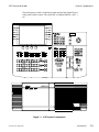
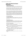
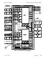


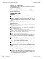
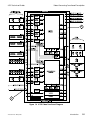
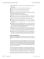


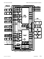
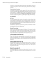
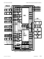

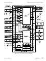

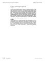


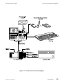
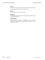


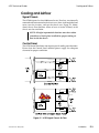
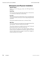
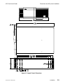

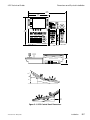


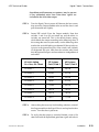
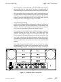

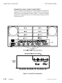

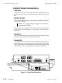

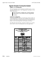

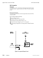


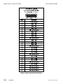

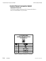
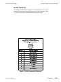
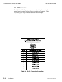
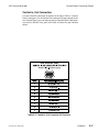


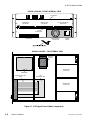
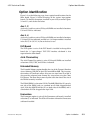
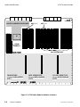


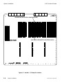


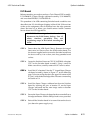

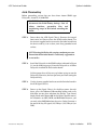


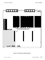
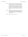
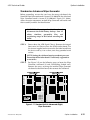
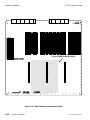

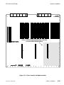

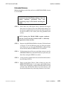


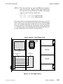


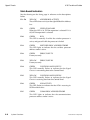

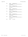
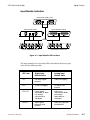
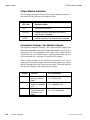
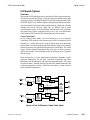
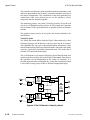
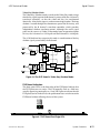


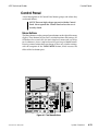
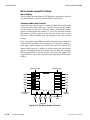
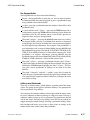
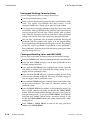
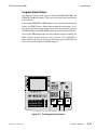
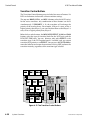
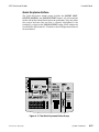
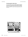

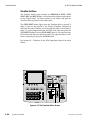


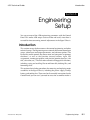

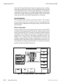
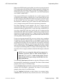
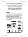
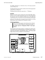
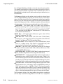
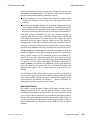
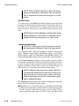

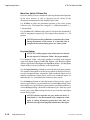

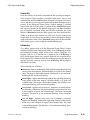


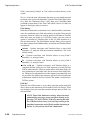
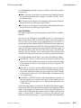

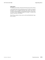
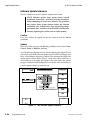

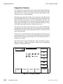
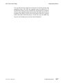
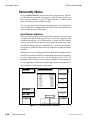

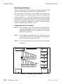

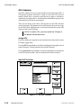
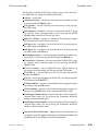

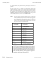


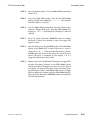

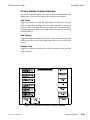


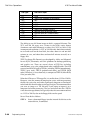


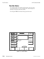

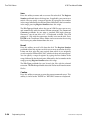
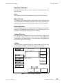
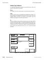

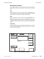
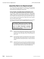
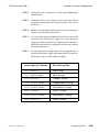
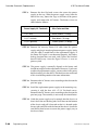

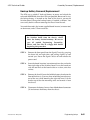


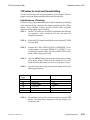

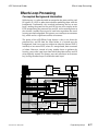


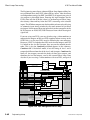


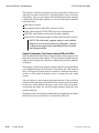
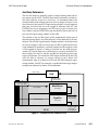
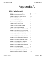
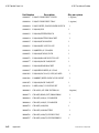
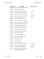


![User's Manual[FBD1] ProMax ProMedia Converter](http://vs1.manualzilla.com/store/data/006881326_1-9e3a0042b45fc9f5f8ff38953ecf78a2-150x150.png)