1
MS-812
Programmable
Main Station
INSTRUCTION
and
SERVICE MANUAL
91
Clearo
Cum
intercom Systems
945 Camelia St. Berkeley, California 94710 510-527-6666
Clear-Com 810124
11/90 REV.A
Clear-Com MS-812 Programmable Main Station
Clear-Com Systems
MS-812 Programmable Main Station
Instruction Manual
P/N 810124
(C) 1990 Clear-Com Systems
All Rights Reserved
Clear-Com Systems
945 Camelia St.
Berkeley, Ca. 94710
US.A
While Clear-Corn makes every attempt to maintain the accuracy of the information contained in its product
manuals, that information is subject to change without notice.
11/90 Rev. 1.0
Clear-Com MS-812 Programmable Main Station
CLEAR-COM LIMITED WARRANTY
Clear-Corn products are warranted to be free from defects in materials
and workmanship, for a period of one year from the date of sale.
Clear-Com's sole obligation during the warranty period is to provide,
without charge, the parts and labor necessary to remedy covered defects
appearing in products returned prepaid to Clear-Com, 945 Camelia St.,
Berkeley, Ca. 94710-1484, U.S.A.
This warranty does not cover any defect, malfunction or failure caused
beyond the control of Clear-Com, including unreasonable or negligent
operation, abuse, accident, failure to follow instructions in the Manual,
defective or improper associated equipment, attempts at modification
and repair not authorized by Clear-Com, and shipping damage. Products
with their serial numbers removed or defaced are not covered by this
warranty.
To obtain warranty service, follow the procedures described below in
"Procedures for Returns" and "Shipping to Manufacturer for Repair or
Adjustment."
This warranty is the sole and exclusive express warranty given with
respect to Clear-Com products. It is the responsibility of the user to
determine before purchase that this product is suitable for the user's
intended purpose.
Any and all implied warranties, including the implied warranty of merchantability are limited to the duration of this express limited warranty.
Neither Clear-Com nor the dealer who sells Clear-Com products is liable
for incidental or consequential damages of any kind.
Return Shipping Instructions
Procedures for returns:
--If repair is necessary, contact the dealer where the unit was purchased.
--If repair through the dealer is not possible, contact the Clear-Com
Customer Service Department, located at the factory, as directed
below. They will issue a Return Authorization Number (RMA).
--Do not return any equipment to the factory without first obtaining a
Return Authorization Number.
--Be prepared to provide your company's name, address, phone number,
name of person to contact regarding the repair, type and quantity of the
equipment, description of the defect, and the equipment serial
number(s).
Questions regarding returns for repair should be directed to:
Customer Service Department
Clear-Com Intercom Systems
945 Camellia Street
Berkeley, California 94710-1484
Telephone: (415) 527-6666
Telefax: (415) 5274699
0
11/90 Rev. 0.2
Page i-2
TABLE OF CONTENTS / Clear-Com MS-812 Programmable Main Station
Shinning IQManufacturer for Repair or Adjustment
All shipments of Clear-Com equipment must be prepaid via United
Parcel Service or the best available shipper. The equipment should be
shipped in the original packing container; however, if the original container is not available, use a suitable container that is rigid and of adequate size. If a substitute container is used, the equipment should be
wrapped in paper and surrounded with at least four inches of excelsior or
similar shock-absorbing material. All shipments should be directed to the
attention of the Customer Service Department and must include the
Return Authorization Number.
Upon completion of repairs, equipment will be returned collect via United
Parcel Service or other specified shipper.
SOFTWARE LICENSE AGREEMENT
Clear-Com Systems ("Clear-Com") provides this software firmware for
the MS-812 and licenses its use. You assume responsibility for the
selection of the firmware to achieve your intended results, and for the
installation and use of, and results obtained from, the program.
'Firmware" in this agreement refers to the operating software stored in
ROMs through the MS-812 MAIN STATION.
License
You may:
1- Use the program only on a single machine;
2. Transfer the firmware and license to another party if the other party
agrees to accept the terms and conditions of this Agreement. ClearCorn grants a license to such other party under this agreement and
the other party will accept such license by its initial use of the
program. If you transfer possession of any copy of the firmware in
whole or in part to another party, your license is automatically
terminated.
The firmware contains confidential information pertaining to ClearCorn. You may not modify, reverse compile, rent, lease, or distribute
the firmware, or any copy, in whole or in part.
Term
11/90 Rev. 0.2
The license is effective until terminated.
Page i-3
TABLE OF CONTENTS / Clear-Corn MS-812 Programmable Main Station
Disclaimer of Warranty
The program is provided "as is" without any warranty of any kind, either
expressed or implied, with respect to its merchantability or its fitness for
any particular purpose. The entire risk as to the ability and performance
of the program is with you. Should the program prove defective, you (and
not Clear-Com or an authorized Clear-Com representative) assume the
entire cost of all necessary servicing, repair or correction. Clear-Com
does not warrant that the functions contained in the program will meet
your requirements or that the operation of the program will be
uninterrupted or error-free, or that defects in the program will be
corrected.
Some States and Provinces do not allow the exclusion of implied
warranties, so the above exclusion may not apply to you. This warranty
gives you specific legal rights, and you may also have other rights which
vary from State to State or Province to Province.
Limitation of Remedies
In no event will Clear-Com be liable to you for any lost profits, lost
savings or other incidental or consequential damages arising from use
of, or inability to use, any program, even if Clear-Com or an authorized
Clear-Com representative has been advised of the possibility of such
damages, or for any claim by any other party.
Some States and Provinces do not allow the limitation or exclusion of
liability for incidental or consequential damages, so the above limitation
or exclusion may not apply to you.
Clear-Com's liability to you for actual damages for any cause
whatsoever, and regardless of the form of the action, will be limited to
the money paid for the firmware that caused the damages or that is the
subject matter of, or is directly related to, the cause of the action.
General
Any attempt to rent, lease, or sublicense the program, or (except as
expressly provided in this Agreement) to transfer any of the rights, duties
or obligations under this Agreement is void.
The Agreement will be construed under the laws of the State of
California, except for that body of laws dealing with the conflict of laws. If
any provision of this Agreement shall be held by a court of competent
jurisdiction to be contrary to law, that provision will be enforced to the
maximum extent permissible, and the remaining provisions of the
Agreement shall remain in full force and effect.
11/90 Rev. 0.2
Page i-4
TABLE OF CONTENTS / Clear-Corn MS-812 Programmable Main Station
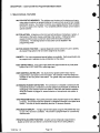
NOTICE ABOUT SPECIFICATIONS
Performance specifications included in this manual are design-center
specifications and are included for customer guidance and to facilitate
system installation. Actual operating performance may vary.
BEFORE YOU BEGIN ...
To get the most out of the MS-812 Main Station, read this manual
carefully. It will answer questions you might have about the operation
and service of the components in the system. Included is a
Troubleshooting Section that provides causes and possible solutions to
problems you might have with system and component operation. ClearCoin's Customer Service Department is available to answer questions
not covered in this manual.
It is assumed you are familiar with the operation of basic intercom
systems.
11/90 Rev. 0.2
Page i-5
TABLE OF CONTENTS I Clear-Com MS-812 Programmable Main Station
0
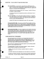
SECTION 1
DESCRIPTION
1.1
1.2
1.3
1.4
1.5
1.6
1.7
1.8
1.9
MS-812 Overall Description
Front Panel Description
Rear Panel Description
Internal Options and Adjustments
MS-812 Possible Configurations
Description of MS-812 Family Products
MS-812 Special Features
Bries Description of Programming
Technical Specifications
SECTION 2
INSTALLATION
2.1
2.1.1
2.1.2
2.1.3
2.1.4
2.1.5
Installation Overview
Cable Considerations
Portable Installation Cable
Permanent Installation Cable
Cable Installation Effects on Cross-Talk
System Power Considerations
2-1
2-2
2-2
2-2
2-2
2-3
2.2
2.2.1
2.2.2
2.2.3
Connection of Intercom Lines
Standard Installation (XLR Rear Panel)
ELCO/EDAC Multi-Pair Cable lnstallation(CP-56)
Tuchel Multi-Pair Installation (CP-30)
2-5
2-5
2-7
2-9
2.3
2.3.1
2.3.2
2.3.3
2.3.4
2.3.5
2.3.5.1
2.3.5.2
2.3.5.3
Miscellaneous Audio Connectors
Program Input #1
SA Output
External Speaker Connection
MA-4 Link Connection
DB-1 5 Auxiliary Audio Connectors
Program Input #2
HOT-MIC Output
Stereo Headset Connection
2-11
2-11
2-11
2-11
2-11
2-12
2-12
2-12
2-12
2.4
DB-9 Logic.Connector
2-12
2.5
Connection lo IFB (PIC04000) System
2-13
2.6
Connection to IS0-4000System
2-15
2.7
2.7.1
2.7.2
2.7.3
2.7.4
Internal Options
Optionsl Program #1 Feed to Speaker
Optional Program Feed to LEFT EAR
Optional GLOBAL SA FEED to ELCO/EDAC
DIP Switch Program Options
2-17
2-17
2-17
2-17
2-17
2.8
Connect MS-812 Intercom to A.C. Power
2-18
11/90 Rev. 0.2
Page i-6
1-2
1-4
1-5
1-6
1-6
1-7
1-8
1-9
1-10
0
TABLE OF CONTENTS / Clear-Com MS-812 Programmable Master Station
SECTION 3
SETUP AND ADJUSTMENT
3.1
3.1.1
3.1.2
3.1.3
3.1.4
3.1.5
Internal Options
Optional Program #1 Feed to Speaker
Optional Program Feed to LEFT EAR
Optional Global SA Feed to ELCO/EDAC
DIP Switch Program Options
AC Voltage Selection
3-1
3-1
3-1
3-1
3-1
3-2
3.2
3.2.1
3.2.2
Internal Adjustments
Panel Microphone Gain Trim
Intercom Line Null (SIDETONE) Adjustments
3-2
3-2
3-2
SECTION 4
OPERATION
4.1
LCD Display
4-3
4.2
4.2.1
4.2.2
4.2.3
4.2.4
4.2.5
4.2.6
4.2.7
4.2.8
4.2.8.1
4.2.8.2
4.2.8.3
4.2.8.4
4.2.9
Description of Front Panel Buttons
'MIC ON' Button
'PANEL MIC' Button
'SPEAKER ON' Button
'PRESET' Buttons
'CALL' Button
'SA' Button
TALK' and 'LISTEN' Buttons
'NEXT and 'BACK' Program Buttons
Selecting Setups (NEXT)
Button Check Function (BACK)
Accessing Programming Mode
Stepping Through Menus
'RESET' Button
4-4
4-4
4-4
4-4
4-5
4-5
4-5
4-6
4-6
4-6
4-7A
4-7B
4-7B
4-7B
4.3
4.3.1
4.3.2
4.3.3
4.3.4
4.3.5
4.3.6
4.3.7
4.3.8
Description of Front Panel Controls
PROGRAM Volume
INTERCOM Volume
PROGRAM FEED Trim Level
SPEAKER MUTE Tmm Level
SIDETONE LEVEL Trim
BEEP TONE Level Trim
LAMP Brightness
LISTEN LEVEL Trims
4-8
4-8
4-8
4-8
4-8
4-8
4-9
4-9
4-9
4.4
Headset Connector
4-9
4.5
4.5.1
4.5.2
4.5.3
4.5.4
Station Programming
Entering Programming Mode
Stepping Through Menus
Sub-Menu Access
Exiting Programming Mode
4-10
4-12
4-12
4-12
4-12
0
-
0Rp.
6/91 Rev. i.i
page i-7
TABLE OF CONTENTS / Clear-Com MS-812 Programmable Master Station
*
*
*
*
*
0
*
*
*
*
*
_
4-12
4-13
4-13
4-14
4-14
4-14
4-15A
4-15A
4-15A
4-15B
4-16
4-16
4-16
4-17
4-17
4-17
4-18
4-18
4-18
4-19
4-19
4-20
4-20
4-21
4.6
4.6.1
4.6.2
4.6.3
4.6.4
4.6.5
4.6.6
4.6.7
4.6.8
4.6.9
4.6.10
4.6.11
4.6.12
4.6.13
4.6.14
4.6.15
4.6.16
4.6.17
4.6.18
4.6.19
4.6.20
4.6.21
4.6.22
4.6.23
Description of Programming Menus
PRESET Assignment
PRESET Operation Mode
FOOTSWITCH Assignment
Enable CALL-IN
CALL-IN BEEP
CALL-IN Activate
CALL-IN Time Out
AUTO CALL-OUT
PROGRAM Feed
PROGRAM Interrupt
Relay Assignments
PRIVATE TALK
PRIVATE LISTEN
LISTENwithTALK
LATCH DISABLE
BUTTON LOCK OFF
BUTTON LOCK ON
PRESET EXCLUDE
Set IFB BUTTONS
Set ISO BUTTONS
Set ISO STATION NUMBER
Set ISO First Channel Number
Rename SETUP
SECTION 5
MAINTENANCE
5.1
5.1.1
5.1.2
5.1.3
5.1.4
5.1.5
5.1.6
Power Supply Descriptions
Ground Isolation
Digital +5 Volts
Digital +15 Volts
Lamp Regulated Supply
+30 Volt Audio Power Supply
Audio Bias and VCA Reference Supplies
5-1
5-1
5-1
5-1
5-1
5-1
5-2
5.2
5.2.1
5.2.2
5.2.3
5.2.4
5.2.5
Microprocessor and Logic Description
Microprocessor Description
Front Panel Logic Flow
Line Drive Module Control
Main Board Audio Control
ExternaL ISO System Interface
5-2
5-2
5-2
5-3
5-3
5-3
5.3
5.3.1
5.3.2
5.3.3
5.3.3.1
5.3.3.2
5.3.3.3
5.3.3.4
5.3.3.5
5.3.3.6
5.3.3.7
5.3.3.8
Analog Description
CLEAR-COM Line Drivers
Use of VCAs
Gain Structure
Dynamic Mic to Internal Talk Bus Gain
Internal Talk Bus to Intercom Line Gain
Internal Talk Bus to Hot Mic and Local SA Gain
Internal Talk Bus to Global Sa Gain
Ballanced Program Inputs to Internal PRG BUS Gain
Internal PRG BUS to Intercom Line Gain
Intercom Lines to Listen Bus Gain
Internal Listen Bus to SPEAKER Gain
5-4
5-4
5-4
5-5
5-5
5-5
5-5
5-6
5-6
5-6
5-6
5-6
6/91 Rev. 1.1
page i-8
TABLE OF CONTENTS / Clear-Com MS-812 Programmable Main Station
5.3.3.9
Internal Listen Bus to HEADSET Gain
5-6
5.4
Trouble Symptoms, Possible Causes & Solutions
5-7
SECTION 6
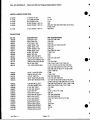
BILL OF MATERIALS
6.1
Chassis Assembly
6-1
6.2
Line Driver Module
6-3
6.3
Front Panel PCB Assembly
6-7
6.4
Main PCB Assembly
6-9
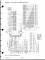
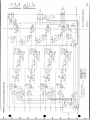
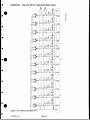
SECTION 7
SCHEMATICS
Figure 7-1
Figure 7-2
Figure 7-3
Figure 7-4
Figure 7-5
Figure 7-6
Figure 7-7
Main PCB Schematic (1 of 2)
Main PCB Schematic (2 of 2)
Front Panel PCB Schematic
Amp Module Schematic
ELCO Module Schematic
XLR Module Schematic
Tuchel Module Schematic
11/90 Rev. 0.2
Page i-9
7-1
7-2
7-3
7-4
7-5
7-6
7-7
TABLE OF CONTENTS / Clear-Com MS-812 Programmable Master Station
ILLUSTRATIONS
Block Diagram
Front Panel
XLR Option Rear Panel
ELCO/EDAC Option Rear Panel
Tuchel Option Rear Panel
1-3
1-4
1-5
1-5
1-5
Figure
Figure
Figure
Figure
Figure
1-1
1-2
1-3
1-4
1-5
MS-812
MS-812
MS-812
MS-812
MS-812
Figure
Figure
Figure
Figure
Figure
Figure
Figure
Figure
Figure
Figure
Figure
Figure
Figure
Figure
2-1
2-2
2-3
2-4
2-5
2-6
2-7
2-8
2-9
2-10
2-11
2-12
2-13
2-14
Installation Showing Termination
Typical XLR System Connection
XLR Rear Panel
Typical ELCO System Connection
ELCO/EDAC Cable Description
30-pin Male Tuchel Connector
Tuchel Option Wiring Diagram
Typical Tuchel System Connection
DB-15 PINOUT
DB-9F PINOUT
Typical IFB Installation
6-Pin IFB Cable Wiring Diagram
Typical ISO Installation
Location of Main Board Option Swftches and Jumpers
2-3
2-4
2-5
2-6
2-8
2-9
2-9
2-10
2-12
2-12
2-13
2-14
2-15
2-16
Figure 3-1
Null Adjustment of Line Drivers
3-3
Figure 4-1
Figure 4-2
Figure 4-3
Front Panel Description
Normal Menu
Extended Menu
4-3
4-10
4-11
Figure 5-1
Input Pad for Mic Gain Measurement
5-5
Figure 6-1
Figure 6-2
Figure 6-3
Amplifier Module PCB Assembly Drawing
Front Panel PCB Assembly Drawing
Main PCB Assembly Drawing
6-2
6-6
6-8
6/91 Rev. 1.1
page i-10
DESCRIPTION / Clear-Com MS-812 Programmable Master Station
SECTION 1
DESCRIPTION OF THE MS-812 PROGRAMMABLE MASTER INTERCOM STATION
THE CLEAR-COM CONCEPT
Clear-Com is a closed-circuit intercom system that consistently provides high-clarity,
communication in high-noise and low-noise environments. A basic system consists of a
single- or multi-channel power supply or main station connected to various single- or
multi-channel remote stations.
Clear-Com manufactures a wide variety of both portable and fixed-installation units. All
are compatible with each other (Clear-Com can also interface with other communication
systems).
Clear-Com stations are interconnected with two-conductor, shielded microphone cable,
using 3-pin XLR connectors. One wire carries the DC power (28-30 volts) from a main
station or power supply to all remote stations, and the other wire carries audio
information. The shield acts as a common ground. One termination (per channel) is
needed throughout the intercom network, and is usually located in the main station or
power supply.
Clear-Com is a distributed amplifier system; each main and remote station houses its
own mic preamplifier (for headset or speaker) and signaling circuitry. The Automatic
Headset Detection circuit shuts off a station's mic pre-amp when the headset is
disconnected, so background noise on the line is not increased by an unused yet on-line
station. Low-impedance mic input lines (200 Ohms) and specially designed circuitry
make Clear-Com channels virtually immune to RFI and dimmer noise.
Clear-Com main stations, power supplies and certain remote stations each have an
auxiliary program input with its own volume control, which allows an external audio
source to be fed to the intercom system.
Visual Signal Circuitry (CALL Lights), a standard feature on most main and remote
stations, allows the user to attract the attention of operators who have removed their
headsets.
Depending upon the type of main and remote stations selected and assuming that
enough DC power is available, a maximum number of remote stations f rom 13 (all
speaker stations) to 100 (all headset stations) can be distributed along a mile of wire.
Remote stations bridge the intercom line at a very high impedance (>15 KOhms), and
place a minimum load on the line. The audio level always remains constant, and does
not fluctuate as stations leave and join the network.
*
The 28-30 volts DC provided by main stations and power supply units enable remote
stations to operate with minimal current (25 mA. quiescent for headset stations, 50 mA.
quiescent for speaker stations) while generating extremely loud listen volumes (greater
than 110dB SPL using Clear-Com Headsets). The higher voltage and low current keep
vohage losses to an absolute minimum in long lines. If the supply voltage drops due to
the addition of great length of cable or many more stations, Clear-Com equipment will
continue operating with less than 12 volts available.
11/90 Rev. 1.0
Page 1-1
DESCRIPTION / Clear-Com MS-812 Programmable Master Station
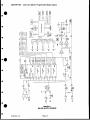
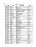
1.1 MS-812 OVERALL DESCRIPTION
The MS-812 Intercom station is a 12 channel fully programmable micro-processor
controlled Master station intended to work with other Clear-Com Party-Line products. All
aspects of the station operation are under micro-processor control with many operational
parameters programmable by the user. An LCD display is used to assist the user in
programming. The user programmed functions are saved in Non-Volatile memory
(EEPROM Memory) and are retained during power-down.
The MS-812 directly supports Clear-Com's IFB and ISO systems. Up to eight channels
of IFB can be controlled directly by the existing front panel buttons. The MS-812 directly
replaces the use of an AX-4 or MA-4 in a PIC-4000 based system. Up to sixteen
channels of Clear-Com ISO-4000 can be controlled directly by existing front panel
buttons eliminating the need for external ICP-4 control modules.
The Line-Drive amplifiers of the unit are built on plug-in modules each containing four
channels. There are provisions for five such modules. Three modules provide twelve
channels of intercom. The remaining two provide eight channels of IFB. If a module is
not used in a given application it need not be installed. These modules are 'hotpatchable' to ease repair.
PHYSICAL DESCRIPTION: The MS-812 is built in a 19 inch rack mount chassis 3 1/2
inches high. The depth is approximately 9 1/4 inches.
POWER SUPPLY IS INTERNAL: The internal power supply is intended to operate only
the internal circuitry of one unit and requires connection to 120/240 VAC 50/60 Hz. The
external Intercom system will need a standard Clear-Com power supply.
SYSTEM INTERCONNECT: A portion of the rear panel is removable offering the user
several options on type of system interconnection. The standard version of the MS-812.
is shipped with 12 XLR connectors for CC intercom lines with line termination jumpers
available from the rear of the unit. Other options available are:
CP-56 -- Two paralleled 56 pin ELCO/EDAC connectors provide Multi-pair cable
connection between stations and Clear-Com's IP-1 200 System Interface Panel.
CP-30 -- Two 30 pin Tuchel connectors wired like a MS-808 for connection into
existing MS-808 systems.
11/90 Rev. 1.0
Page 1-2
DESCRIPTION / Clear-Com MS-812 Programmable Master Station
S~~~~~~~~~~~~~~~~~~~~~~~~~~~~S
F
.
~~~~_
71
0
OM
I
S~~~~~
Er 1i~~~~~~~~~~~
9-1~~~~~~1
b
1.
1*-
*~~~~~~
~
Rev 1.
11/90
0
't
LL
.
Pag 1 -3
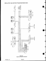
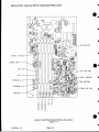
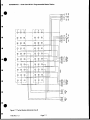
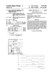
FIGURE 1U
MS-812 BLOCK DIAGRAM
11/90 Rev. 1.0
.Page 1-3
p
I a
e
DESCRIPTION / Clear-Corn MS-812 Programmable Master Station
0
R0
10
I
i,
2
a
*
w
T
a
fi
10
18
12
,'
-
~@
ao
0
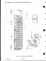
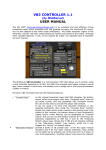
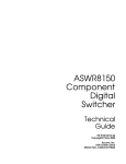
FIGURE t2
FRONT PANEL
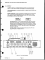
1.2 FRONT PANEL DESCRIPTION
All front panel pushbuttons, except the two programming buttons, are illuminated and under
control of the micro-processor. The legends in the keycaps are removable and changeable by
the user. The overall brightness of the button illumination is set by a front panel trim control.
-- PANEL MOUNT ELECTRET
-- HEADSET JACK (MONO)
-- FRONT
-- MIC
0
MICROPHONE
PANEL SPEAKER
ON/OFF Button and ON indication.
-- PANEL MIC SELECT Button and indication.
-- SPEAKER ON/OFF Button and ON indication.
PRESET Buttons (Programmable)
Button (Stage/Studio Announce)
--CALL FUNCTION Enable Button
-- 4
-- SA
-- 24 SELECTOR Buttons
-- 12 LISTEN LEVEL Trim Controls
Listen Level Control
-- MASTER Intercom Level Control
-- PROGRAM
--8 Char X 2 Row LCD Display
--2 PROGRAM SETUP BUTTONS
-- DEFAULT RESET BUTTON (Accessible through a hole between SETUP buttons)
-- TRIM CONTROLS:
11/90 Rev. 1.0
PROGRAM FEED LEVEL to intercom Lines
SPEAKER MUTE LEVEL
BEEP TONE LEVEL (Speaker only)
LOCAL SIDETONE LEVEL (Headphone only)
LAMP INTENSITY
Page 1-4
0
DESCRIPTION / Clear-Com MS-812 Programmable Master Station
ro~~~o
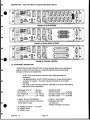
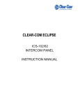
FIGURE 13 (XLR OPTION)
Jo s muS
1
[~~~~~~~~~~~~~~
_
*
_~~0
~~~~~~~~~~
0
O u st
wh~~~~~~~afl~~~
FIGURE 14 (ELCO/EDAC OPTION)
0
o
_,0U
__
0
FIGURE 1.5 (TUCHEL OPTION)
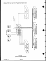
1.3 REAR PANEL DESCRIPTION
--INTERCOM SYSTEM CONNECTIONS: To accommodate different sizes and types of
systems a section of the rear panel is a removable plate allowing several optional
connector schemes to be implemented.
12 XLR Clear-Com Intercom connectors with jumper selectable line
terminators.
-- Two paralleled 56 pin ELCO or EDAC connectors to provide loop-through or
connection to a system. This option requires termination to be provided
externally.
-- Two 30 pin Tuchel connectors wired like a MS-808 for connection into existing
808 systems with no termination.
--
INPUT #1: ----- (XLR-3F)
(XLR-3M)
(1/4 " Phone)
-- MA-4 Link ---------------------- (1/4 " Phone)
-- PROGRAM
-- SA OUTPUT: ------------------ EXT. SPEAKER --------------
-- A DB-9F "RELAY/FOOTSWITCH':
2 SETS of LOCAL RELAY CONTACTS
FOOT-SWITCH input.
^
-- ISO/IFB OPTION:
TWO IFB FEEDs: ---------- (XLR-6M)
ISO-4000 Transfer Audio- (XLR-3M)
ISO-4000 Control ---------- (XLR-6M)
-- A DB-15F "AUX AUDIO"
PROGRAM INPUT #2
HOT-MIC OUT
HEADSET Connection
~~~~~~~~~~~~STEREO
-- AC POWER Connector ---- (CE 22/V)
-- AC POWER Switch
-- AC POWER Fuse
11/90 Rev. 1.0
Page 1-5
DESCRIPTION / Clear-Com MS-812 Programmable Master Station
1.4 INTERNAL OPTIONS AND ADJUSTMENTS
NULL adjust controls for all line drivers.
-- GAIN TRIM for the PANEL MICROPHONE (+/- 5 dB).
-- DIP SWITCHES for enabling PROGRAMING options.
-- AC POWER Voltage SELECTION
-- INTERNAL JUMPERS provide user options:
-- SIDE-TONE
Listen feed from Program #1
Left Ear Program Feed
SA Feed to ELCO Cable
1.5 MS-812 POSSIBLE CONFIGURATIONS
0
The internal circuitry of the MS-812 is constructed to accept up to five 4-channel Line
Driver modules. Various configurations and sizes of the machine can be realized. Line
Driver modules support intercom and external IFB channels.
The following are the common configurations:
--2 Modules-8 Ch Intercom
8 Ch Intercom & 4-8 Ch ISO
0
--3 Modules-12 Ch Intercom
10 Ch Intercom & 4 Ch ISO
8 Ch Intercom & 4 Ch IFB
8 Ch Intercom, 4 Ch IFB, & 4 Ch ISO
4 Ch Intercom, 8 Ch IFB, & 8 Ch ISO
0
--4 Modules-12 Ch Intercom
10 Ch Intercom & 4 Ch IFB
8 Ch Intercom & 8 Ch IFB
6 Ch Intercom, 8 Ch IFB, & 4 Ch ISO
*NOTE: Reclocation of modules will be necessary to realize some of these possible
configurations. If all possible combinations are needed under software selection then 5
Modules are needed.
11/90 Rev. 1.0
Page 1-6
a
5
DESCRIPTION / Clear-Com MS-812 Programmable Master Station
1.6 DESCRIPTION OF MS-812 FAMILY PRODUCTS
MS-812-8 -- This model is shipped with two line amp modules and an XLR back-panel.
ISO/IFB options are not installed. This model provides eight channels of intercom.
MS-812-12 -- This model is shipped with three line amp modules and an XLR packpanel. ISO/IFB options are not installed. This model provides twelve channels of
intercom.
IFB-40 -- is a four channel IFB and ISO Option that adds one additional line amplifier
module to the station and rear panel connectors are installed for IFB and ISO
operation.
IFB-80 -- is an eight channel IFB and ISO Option that adds two additional line amplifier
modules to the station and rear panel connectors are installed for IFB and ISO
operation.
ISO-16 -- is an option that provides just the rear panel connectors installed for IFB and
ISO operation.
0
710229 -- is the Four Channel Line Driver module and can be ordered separately for
expansion of an existing system.
CP-56 -- is the dual "loop thru" ELCO/EDAC 56 Pin Connector Option panel for the rear
panel for interconnecting stations via a single muhti-pair cable.
CP-30 -- is the dual "loop thru" TUCHEL 30 pin Connector Option Panel for the rear
panel for interconnecting into an existing MS-808 system using the mufti-pair cable
used in that system.
IP-1200 -- is an interconnect panel designed specifically to terminate and provide
individual channel breakout when interconnecting MS-812's with an ELCO cable. This
panel also provides power distribution with overload protection for external individual
intercom lines such as Belt Packs.
The IP-1200 also has program inputs that can be feed to all MS-812s connected. Also,
a global SA output is available that any of the MS-812s can feed. There are four relays
in the IP-1200 that any of the MS-812s can operate.
ELCO CABLES -- Pre-made 56 Pin multi-pair ELCO/EDAC cables are available both
from Clear-Com and independent sources. Contact factory for details.
11/90 Rev. 1.0
Page.1-7
DESCRIPTION / Clear-Com MS-812 Programmable Master Station
1.7 MS-812 SPECIAL FEATURES
MULTIPLE SETUP MEMORIES: The attributes and functions of the buttons and many
other station functions are programmable by the user and are saved in Non-Volatile
(EEPROM) memory. Four banks of memory are available allowing FOUR complete
SETUPs to reside in the machine. Four completely different setups can be ready to
operate anytime.
BUTTON ACTION: All buttons on the front are both latching or momentary in action. A
short press of the button causes a latching of the function. Holding the button
causes the button press to only have action while the button is pressed
(momentary). The latching function of any button can be disabled in the
programming mode.
BUTTON CHECK FUNCTION: A special diagnostic function allows the user to identify
all programming options that have been assigned to any button.
PRESETS: Four user programmed preset buttons are available. Each preset button can
be programmed to operate any key combination on the station.
FOOT SWITCH INPUT: A rear panel input allows the logical control of any front panel
function via a FOOT SWITCH or other logic input.
USER CONTROLLED RELAYS: Two local and four global system relays may be
programmed to any button on the front panel. The contacts of the local relays are
available on the rear panel of the station. The 'global relays are located external to
the station.
AUTOMATIC HEADSET DETECTION: The connection of a headset is sensed and the
Headset Microphone is switched on and the Speaker and Panel Mic is switched off.
Unplugging of the headset returns the station to Panel Mic and Speaker operation.
While the headset is plugged in, manual selection of microphones and speaker is
available.
TWO PROGRAM FEEDS: Rear panel connectors allow program inputs for two different
purposes. One directly feeds the Speaker or Headphone through a front panel level
control. The other is used to selectively feed the 12 intercom channels.
PROGRAM INTERRUPT: A single channel interruptible program (PROGRAM #2) feed
to each TALK channel is available. This function is programmable on a channel by
channel basis.
PRIVATE TALK/LISTEN FUNCTION: A button can be temporally programmed to
disable all other talks and listens to all channels except the one being talked to.
11/90 Rev. 1.0
Page 1-8
DESCRIPTION / Clear-Corn MS-812 Programmable Master Station
S.
CALL IN FUNCTION: An incoming CALL signal will flash the LISTEN button for the
channel. The flashing CALL indication will time out and disappear after a preset time
period. This time out period is programmable. Whether or not a CALL signal can be
received on a particular channel is programmable.
A BEEP will sound in the speaker when a CALL is received. The BEEP TONE can
be disabled or enabled individually.
An incoming call signal can be programmed to activate a LISTEN and/or TALK on
that channel.
CALL OUT FUNCTION: A CALL button allows sending a call signal out. Pressing the
CALL button enables the CALL function. If while the CALL function is enabled, one
or more of the TALK buttons is pressed, a CALL signal will be sent to that channel.
The CALL function will automatically time out.
Individual TALK buttons can be programmed to send a CALL when pressed.
IFB (CLEAR-COM PIC-4000): There are two 4-channel IFB ports available on the rear
panel intended to feed a Clear-Com PIC-4000 IFB system. A programming option allows
the user to assign,in groups of two, up to eight of the 24 selector buttons to IFB control.
Assigning buttons to IFB control takes them away from INTERCOM use. An internal DIP
switch enables the MENU item for this function.
S.
ISO (CLEAR-COM IS0-4000): The station is designed to connect directly to Clear-Com's
ISO-4000 Station Isolation System. A remote station (such as a camera) can be isolated
from its normal intercom channel and talked directly to by the ISOing station. A
programming option allows the user to assign,in groups of two, up to sixteen of the 24
selector buttons to ISO control. An internal DIP switch enables MENU items for this
function.
1.8 BRIEF DESCRIPTION OF PROGRAMMING
Most operating parameters of the MS-812 are user programmable making the unit
extremely versatile. A two-line by eight character LCD display helps the user in
programming by clearly identifying the menu functions. Stepping through the various
menu items is done by repeatedly pushing and releasing two SETUP buttons. One
SETUP button steps the MENU forward and the other backwards.
Once a menu item is selected the micro-processor guides the user by flashing available
buttons for a given programmable function.
The programing Menu is divided into two levels of complexity. Access to the second
level (EXTENDED) is enabled by an internal DIP switch.
-- NORMAL:
Basic menu items necessary to operate the station for a majority of
applications.
--
EXTENDED: Added menu items allowing the user more complex use of the machine.
-- INTERNAL
DIP SWITCH OPTIONS: A series of internal DIP switches enables special
function menus. These DIP switches only affect the availability of the related menus.
11/90 Rev. 1.0
Page 1-9
DESCRIPTION / Clear-Com MS-812 Programmable Master Station
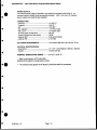
1.9 TECHNICAL SPECIFICATIONS:
CONTROL SYSTEM: An 8 bit microprocessor (Motorola 68HC11) wth 16K bytes of
program memory, 4 K bytes RAM, and 512 bytes EEPROM.
AMPLIFIER DESIGN: IC Amplifiers are used extensively. All signal switching is CMOS
logic controlled switches. Front panel control of Audio levels is through the use of VCAs.
MICROPHONE PRE-AMP:
--Dynamic Headset Input: ------------------------- Input Impedance - 200 Ohms
Input Level - -55 dBv' nominal
Input Level - -10 dBv* max.
--Panel Mic Input Level: ---------------------------- Input level - -41 dBv nominal.
Input level adjustment range - +/-5 dB.
--Frequency Response: ---------------------------- 250 Hz to 12 KHz, contoured for intelligibility.
--Limiter Range: -------------------------------------- 20 dB
--Gain from Headset to Intercom Line: --------- +41 dB
HEADPHONE AMPLIFIER:
--Load Impedance: --------------------------------- 50-2000 Ohms
--Output Level: ---------------------------------------- at least +20 dBv* across 600 ohm
- <0.2% THD at 1 KHz
--Distortion: --------------------------------Frequency Response: --------------------------- 150-18KHz +/-2dB
--Gain from Intercom Line: ------------------------- +37 dB
SPEAKER AMPLIFIER:
--Load Impedance: ----------------------------------- 8-50 Ohms
--Output Power: --------------------------------------- 4 Watts into 8 ohms
--Distortion: ------------------------------------------ <0.5% THD at 1 KHz
-- Frequency: ------------------------------------------- 200 Hz to 15 KHz +/- 2 dB
--Gain from Intercom Line: ------------------------- +41 dB
PROGRAM INPUTS:
--Input Level Ref.: ----------------------------------- -15 dBvt
--Input Impedance: ---------------------------------- >10 KOhms
--Frequency Response: ------------------------------ 150 Hz to 18 KHz
INTERCOM LINE DRIVE/RECEIVE CIRCUITS:
>-10 KOhms (200Hz - 10 KHz)
----Impedance, Output Load: dBv'
-9
--------load):
ohm
--Level, Nominal Line (200
dBv
+5
--Level, Max Before Clipping (200 ohm load):
dB (200Hz - 10 KHz)
>
25
--------------------- Sidetone Null Capability: --Crosstalk, Station Induced Ch. to Ch.: ------- >60 dB
--Noise, SN Ratio in Listen Channels: --------- >60 dB
INTERCOM SYSTEM SPECIFICATIONS (STANDARD CLEAR-COM):
Usable Line Quality: up to 100 Stations and 5000 feet of line.
Crosstalk: For 2 lines terminated at one end the crosstalk at the far end shall be: 500 ft <
-52dB
11/90 Rev. 1.0
Page 1-10
DESCRIPTION / Clear-Com MS-812 Programmable Master Station
POWER SUPPLY:
The internal power supply is intended to only power the internals of the MS-812. An
external intercom System must be powered externally. +30V, +15V, and +5V internal
power supplies are electronically regulated.
CONNECTORS:
-- Intercom: --------------------------------------------- 12 XLR-3
-- Program: -------------------------------------------- XLR-3F '
--SA: --------------------------------------------------- XLR-3M '
1/4" Phone Jack
--Ext. Speaker: ----------------------- -- MA-4 Link: ------------------------------------------ 1/4" Phone Jack
--Auxiliary Audio Connections: ------------------- DB-15F
--Control (Relays and Foot-switch): ------------- DB-9F
--Optional ISO: -------------------------------------- XLR-3M & XLR-6M
--Optional IFB: --------------------------------------- 2 XLR-6M
AC POWER REOUIREMENTS: ----------------- 105-130/210-260 VAC, 48 to 62 Hz, 40 VA
PHYSICAL SPECIFICATIONS:
---Dimensions: ---- -------Weight: -
-
19" x 3.5" x 9.25 (483mm x 89mm x 235mm)
12.0 lbs (5.5 Kg)
WORKING TEMPERATURE RANGE: -------- 32-122 F (0-50 C)
0
' - OdBv is referenced to 0.775 volts RMS.
Specifications subject to change without notice.
*' - All marked circuits appear on the 56-pin ELCO/EDAC Mufti-Pin connectors.
11/90 Rev. 1.0
Page 1-11
INSTALLATION / Clear-Com MS-812 Programmable Master Station
SECTION 2
INSTALLATION OF THE MS-812 PROGRAMMABLE MASTER INTERCOM STATION
Before You Begin:
Upon receiving the equipment, inspect the shipping boxes for shipping damage- Report
all shipping damage to the carrier. Clear-Com is not responsible for damage caused in
shipping.
-
Count and verify receiving all items on the packing list. Do not discard packing materials
until all items are found. Clear-Com recommends that your retain the shipping material
until after the system is completely installed and working, in case some htem must be
returned to Clear-Com for warranty service.
2.1 INSTALLATION OVERVIEW
The MS-812 is a very versatile intercom station. Installations can vary widely depending
on what features are used. The following sections will deal with each feature or group of
connectors on the rear panel as they are independent functions.
The overall intercom system should be planned prior to installing a particular station. The
following steps should be followed before installing any given station:
1. Create block diagram the entire system. Plan intercom line termination locations.
2. Identify accessory equipment to be used with the system.
3. Plan powering of remote stations and accessory equipment as the MS-812 does
not supply system power.
4. Identify station locations.
5. Plan and install cable runs.
6. Identity and set or install internal options in MS-812 stations.
7. Install the MS-812.
8. Check out the hardware installation by exercising the station.
9. Enter the program mode of each individual station and set the desired program
options.
CAUTION: All Clear-Com Intercom lines must be terminated. Care must be taken not
to tail to terminate or to 'double' terminate a line. All unused intercom inputs should
be terminated to keep the line drive circuits stable.
Clear-Com provides a complete line of intercom products. An important part of this
product line is a series of Interface products that allow a user to link Clear-Com with
virtually any type of communication system or equipment. The following is brief
descriptions of these products:
AC-10K ---- Universal interface. Clear-Com to 2, 3, or 4 Wire circuits.
AC-10H ---- Telephone interface. Clear-Com to telephone lines.
IF4-4 ------- 4-Wire/Camera interface. Four channels of Clear-Com to 4 Wire
conversion.
TW-12B ---- System to System Interface. Provides ground isolation and correct
termination between two Clear-Com systems and/or conversion
from Clear-Com to RTS systems.
TWC-1OA -- TW line converter. Converts two Clear-Com lines into a two channel
single pair format for two channel 'TW" behtpacks.
TWC-104 -- Four Channel TW line converter. A Four channel version of the
TWC-1 OA.
0
11/90 Rev. 1.0
Page 2-1
INSTALLATION / Clear-Com MS-812 Programmable Master Station
2.1.1 CABLE CONSIDERATIONS:
The Clear-Com intercom line is intended to run on a shielded twisted pair of
cable per channel of intercom. One conductor carries full duplex ("two-way")
audio, the other conductor carries the DC power for remote stations. The shield
is used for ground return for audio and power. When choosing interconnect
cable, keep the following considerations in mind:
1. DC resistance of the ground or common conductor affects crosstalk. For runs
longer than 100 feet do not use wire smaller than 20 gauge. The total
resistance of the ground return (the combined parallel sum of all shields to a
location) to any point in the system should be under 1.5 ohms.
2. The capacitance of the interconnect cable affects system frequency response
and side-tone stability. Total capacitance should not be greater than 0.25 uF
(capacitance between conductor and shield) equivalent to an intercom system
containing 5000 feet of cable at 50 pF per foot.
2.1.2 PORTABLE INSTALLATION CABLE
Typical cable for portable system interconnections is rubber-jacketed, twoconductor, shielded microphone cable. For runs less than 500 feet a cable made
of 24 gauge wire is acceptable. For runs longer than 500 feet use a 20 gauge
cable or larger.
Portable remote stations such as belt-packs each have a pair of input and output
connectors; when installing a system that includes these, they can be daisychained along one interconnect path. Clear-Com provides a one input by three
output Line-Splitter (QP-1 00) that can also simplify wiring. Daisy-Chaining and
Line-Splitting decreases the amount of cable required and simplifies the
installation.
2.1.3 PERMANENT INSTALLATION CABLE
Vinyl-jacketed shielded pair is the cable of choice for permanent installations.
Use a low-capacitance 20 gauge wire for short runs (under 500 feet) and 18
gauge cable for runs greater than 500 feet. Placing the cable in conduit is
recommended but not necessary.
Multi-pair cable that is individually shielded is acceptable for use in multi-channel
systems. For cross-talk considerations the shields must be tied together on both
ends of the cable to produce the lowest possible DC path for ground return.
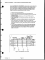
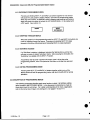
2.1.4 CABLE INSTALLATION EFFECTS ON CROSS-TALK
When multiple channels are fed to remote stations, the amount of cross-talk
between channels is proportional to the amount of DC resistance in the around
return gah-back to the termination of the channels. The cable used in ClearCorn's ELCO multi-pair cables has a combined shield resistance of 0.11 ohms
per 100 ft. The crosstalk due to cable resistance is predictable with the following
chart:
100fa --- 61 dB
300 ft. --- 57 dB
500 ft. --- 52 dB
11/90 Rev. 1.0
700 ft.
900 ft.
Page 2-2
-----
50 dB
48 dB
INSTALLATION / Clear-Corn MS-812 Programmable Master Station
This cross-talk is not present on both ends of the cable. The terminated end of
the cable will not contain the cross-talk. The remote end of the cable will have
the cross-talk as it is generated in the ground return and not the audio line.
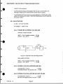
The ideal installation would have all multi-channel cables originate from a central
point. The termination for each channel is located at this central point. This type
of installation is known as a "Star" type system. If no single multi-channel leg of
the "Star" arrangement exceeds 500 ,ftthe crosstalk should be negligible.
TERMINATION
|
T
-
-=[
Unacceptable Installation
|- <
500 Ft.
Se
]-
< 500 FLtv
Recommended Installation
Figure 2.1
Two of the rear panel options for the MS-812 facilitates the use of multi-pair
cable in a daisy-chain environment. This configuration will produce acceptable
results if the length of any given leg from the central termination location is less
than 500 ft. An accessory designed special for use with the MS-812, the IP1200, would provide a central termination point for the system. The IP-1 200 has
three paralleled multi-pin connectors providing an easy method of implementing
a "Star' arrangement. The IP-1 200 also provides breakout connectors with
power distribution and overcurrent protection to readily interface to un-powered
remote stations.
2.1.5 SYSTEM POWER CONSIDERATIONS
The MS-812 is self-powered and does not require DC power from the intercom
line. Two or more MS-812s may talk to each other without the need for an
external power source.
The MS-812 does not provide any power for external devices, therefore if remote
stations that require external power are to be used with a MS-812 an external
power source must be provided.
Clear-Com provides a variety of Power Supplies, specially designed for use with
Clear-Com equipment. These power supplies have special characteristics and
protection that is ideal for intercom service. Other sources of +30 VDC may be
used but Clear-Com only guarantees the proper operation of the equipment with
Clear-Com power supplies are used.
11/90 Rev. 1.0
Page 2-3
INSTALLATION / Clear-Com MS-812 Programmable Master Station
U)~~~~U
aw
w0 b
a)
F
Li
0
St
@:
00
_<000
0on
Ld
MI MI
-rDVM=
0
0
U)
~~
~
~~~~~~~~c
~
~
0
UJD
UJ
z6
0
0
Lii
.00
0~~~~~~
a~~~~~~~~~~~~~~~
00
C~~~~~~~~~~~~~~~~
0
a
-
L-
0
10
0
a
i~0
0
ii
0
00
0
00~~~~~~~
0
0
Figure 2.2
Typical XLR System Connection
11/90 Rev. 1.0
Page 2-4
INSTALLATION / Clear-Com MS-812 Programmable Master Station
*
2.2 CONNECTION OF INTERCOM LINES
Section 2.2 only deals with intercom system connection through the use of the three
optional connector panels available. Other audio and control connections are discussed
in Sections 2.3 to 2.8.
2.2.1 STANDARD INSTALLATION (XLR REAR PANEL)
0~~~~~~~~~
IF2
3
2.3
0~~~~~~~
Figure 2.3
XLR Rear Panel
12 XLR CONNECTORS: Twelve male XLR connectors provide intercom line connection
to the MS-812. The following pin-out represents only the XLR panel.
PIN-1
PIN-2
PIN-3
-- Intercom
-- Intercom
Ground (Common to all 12 connectors and intercom ground).
Power (Common to all 12 connectors only).
-- Intercom Audio (Twelve individual intercom lines with selectable
termination on the side of the Panel).
CAUTION: The PIN-1 Ground must be isolated from chassis ground in all cases. In
cable preparation be careful not to internally connect the shell of the XLR to PIN-1.
TERMINATIONS: Two jumper fields on the rght side of the panel allow individual
channel termination. The OFF connector field is provided as a "PARK" position so that
the Jump-Jack will not be lost.
CAUTION: All Clear-Com Intercom lines must be terminated. Care must be
taken at to Q'double' terminate a line All unused intercom inputs should be
terminated to keep the line drive circuits stable.
POWERING OF A SYSTEM EXTERNAL TO THE MS-812: The PIN-2s of the twelve
connectors are connected together. If +30 Volts DC is applied to one of the twelve
connectors it will appear on the other eleven.
EXAMPLE: Connecting a Clear-Com MS-200C to channels 1 and 2 of the MS-812
will place +30 Volts on all of the PIN-2s of the XLR panel. A line of RS-501 Beltpacks will now be powered on Channel #3 from the MS-200C internal power supply.
In this example the source of termination for Channels 1 and 2 could be either from
the MS-812 or the MS-200C.
11/90 Rev. 1.0
Page 2-5
INSTALLATION Clear-Com MS-812 Programmable Master Station
0
0
0@
00
00
ovv
~
IN
0
~
on
loD
~~~~~
A
~~~~~~~~~~0
x
0
0
00
0~~~~~~~~~~~
of~<=)
=
rn
0
11/90 Rev. 1.0
YO~
~
d
~~~~~nd
Page 2-6~~~~~~~0
0
D00
0~~~~
00~~
Figure 2.4
Typical ELCO System Connection
11/90 Rev. 1.0
Page 2-6
INSTALLATION / Clear-Com MS-812 Programmable Master Station
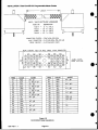
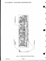
2.2.2 ELCO/EDAC MULTI-PAIR CABLE INSTALLATION (CP-56)
Through the use of the ELCO series 8016 56 pin cable connector, easy
connection between multiple MS-812s and other system components can be
quickly realized. The brand name 'EDAC' is a second source for ELCO
products. The IP-1200 System Interface Panel is designed specifically to mate
with the MS-812 using this cable format.
A STAND ALONE MS-812 SYSTEM: An 12 channel intercom system, with
many MS-81 2s, could be easily configured using just the 16 pair ELCO cables.
Daisy-chaining is quickly accomplished with the loop-through connectors on the
CP-56. Termination would need to be placed in a blank connector at one of the
end stations in the daisy-chain path. An ELCO connector with solder terminals
could be used to construct the 12 termination networks necessary. Each MS812 provides its own power so no power distribution is necessary.
TWO ACCESSORY XLR CONNECTORS: It will be noted that there are also
two XLR connectors on the CP-56 option panel. These two connectors are
intended for local feed of up to two channels of intercom from any MS-812.
Removal of the CP-56 panel will reveal that the two connectors are jumper
connected to channels 1 and 2 of the system. Easy reassignment of these XRL
connectors is accomplished by moving the jumpers to the desired channel. No
power is available on these connectors for operating a remote station. A two
channel main station (CS-210) or power supply (PS-20) would easily provide this
function.
16 PAIR CABLE FEATURES: This 16 pair cable scheme provides a path for a
number of system signals:
-- 12
--
intercom Lines
System SA Feed
-- System Program Feed
-- System Wide Control of 4 Global Relays located in the IP-1200
IP-1200 SYSTEM INTERFACE PANEL: The IP-1200 provides a number of
functions necessary to tie a system together:
-- Two
XLR-3M connectors per channel providing multiple feeds to
external intercom components.
-- Switchable line terminations for each of the twelve intercom lines.
-- A single XLR connector provides input from an external power supply
for distribution of DC power to the XLR connectors with individual
circuit breakers for each channel. Each channel also has power
GOOD and FAULT LEDs per channel.
-- A transformer isolated XLR-3F input of Program for distribution to all MS-81 2s.
-- A transformer isolated XLR-3M output of a common SA bus from all MS-81 2s.
-- 4 sets of Form-C contacts of relays that can be controlled by any MS-812.
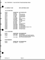
DESCRIPTION OF 16 PAIR ELCO CABLES: Clear-Com provides a variety of
lengths of these 16 pair cables already assembled. Custom lengths can be
assembled to customer order. Please contact your dealer or the Clear-Com
sales department for more information. Figure 2.x on page 2-8 describes these
cables.
11/90 Rev. 1.0
Page 2-7
INSTALLATION/ Clear-Corn MS-812 Programmable Master Station
~~~~~~LENGTH
t-
0
MALE / MALE MULTICABLE ASSEMBLIES
PART NO.
-
730119
730120
730121
730122
-
DESCRIPTION
10 Ft. CABLE
25 Ft. CABLE
50 Ft. CABLE
100 Ft. CABLE
CONNECTOR COVERS = EDAC# 516-230-556
MALE CONNECTOR = ELCO #00-8016-056-000-601
CRIMP CONTACT = ELCO# 60-8017-0323
REAR (WIRING) VIEW OF MALE CABLE (-601) CONNECTOR.
B
°O
8 0
(i)
PIN
WIRE
COLOR
1H
1C
2H
RED
BLK
WHT
2C
3H
BLK
GRN
3C
BLK
4H
4C
5H
BLU
BLK
5C
YEL
BLK
6H
BRN
6C
BLK
ORG
BLK
WHT
RED
7H
7C
8H
8C
As8
ASGMT
INT. #1
G. RELAY
INT. #2
G. RELAY
INT. #3
G. RELAY
INT. #4
G. RELAY
INT. #5
11:
8
I
#1
145
WIRE
COLOR
9H
9C
10H
10C
GRN
RED
BLU
_
14C
INT. #7
15H
_
15C
INT. #8
16H
RED
YEL
RED
BRN
RED
ORG
RED
WHT
GRN
BLU
GRN
YEL
16C
GRN
#2
llH
INT. #6
11C
12H
12C
13H
13C
14H
_
#3
#4
Page 2-8
CABLE EXITS
w
00
®
FROM THIS END
0g
8
Figure 2.5
ELCO/EDAC Cable Descriptions
10/91 Rev. 1.1
Q
14
K>
6C
6SD
150
ASGMT
INT. #9
_
INT. #10
_
INT. #11
_
INT. #12
-
PRG. #1
PRG #2
_
SA
-
INSTALLATION / Clear-Com MS-812 Programmable Master Station
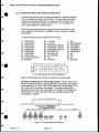
2.2.3 TUCHEL MULTI-PAIR CABLE INSTALLATION (CP-30)
This option provides two 30 pin Tuchel male connectors (in parallel) wired "pinfor-pin" compatible with Clear-Com's MS-808. This option allows an MS-808
installation to expand using MS-81 2s. All functions that are provided in the
Tuchel from the MS-808 is available in the MS-812s. The next page (2-10)
shows a block diagram of a typical system.
MS-812s connected together with this cable style can communicate to each
other regardless of the presence of MS-808s or without the need of a system
power supply.
The following chart is the pin assignment of the Tuchels:
Al - INTERCOM-1
A2 - INTERCOM-2
A3 - INTERCOM-3
A4 - INTERCOM-4
A5 - INTERCOM-5
A6 - INTERCOM-6
A7 - INTERCOM-7
A8 - INTERCOM-8
A9 - INTERCOM-9/IFB-1A
AO-GROUND
.0
*;'-j-L
.IA
1 F4
T
_.
0
_
N2
Bi - + 30 Vohts
Cl - N/C
B2 - + 30 Volts
B3 - INTERCOM-10/1FB-2A
B4 - INTERCOM-11/1FB-3A
B5 - INTERCOM-12/IFB-4A
B6 - IFB-lA/IFB-1B
B7 - IFB-2A/IFB-28
B8 - IFB-3A/IFB-2B
B9 - N/C
B0-GROUND
C2 - IFB-4A/IFB-4B
C3- PROGRAM 1
C4- PROGRAM 1
C5 - PROGRAM 2
C6 - PROGRAM 2
C7 - N/C
CB - N/C
C9 - N/C
CO-GROUND
C
M vP
=
.
=
=
C
=
0a= IC
== =
=~
2
Q=
====
=
=
=
mDO
W
Q
C
=
=
°
=
/A
Figure 2.6 30 Pin Male Tuchel Connector Viewed From Inside Chassis
OPTIONAL CONNECTION OF THE TUCHEL OPTION: Pins 9A, 3B, 4B, and
5B show an optional purpose. By placing the header connected to these pins on
J24 for intercom 9-12 or J25 for IFB-A these options can be implemented. Pins
6B, 7B, 8B, and 2C also have a dual purpose. The header for these pins is
intended to plug into J25 or J26. See Figure 2-14 on Page 2-16 for location of
these headers. For more information refer to the schematic diagram of the
Tuchel option in Chapter 7.
0NT
1-4
J22
INT 5-C
J23
INT 9-12
J24
IFB 1-4
J25
IFB 5-8 RELAY 1-4
J26
411
IS0
J13
Figure 2.7 Tuchel Option Wiring Diagram
11/90 Rev. 1.0
Page 2-9
SA
J15
iS
.
INSTALLATION / Clear-Com MS-812 Programmable Master Station
Or
I
lI I
0~~~~~~~~~~
ao- To
1M
00
1
0
*Z
00
0~~~~~~~~~
00
00
N
CO
00
oZ
On
D00
0~~~~~00
0L C0
00
0~~
On
11/90 Rev. 1.0
Page 2-10
INSTALLATION / Clear-Com MS-812 Programmable Master Station
2.3 MISCELLANEOUS AUDIO CONNECTIONS
There are several other connectors on the rear panel. Each of these connectors have a
special purpose.
2.3.1 PROGRAM INPUT #1
The female XLR marked PGM-1 is a balanced program input that can be fed to
the intercom lines with optional interrupt. An internal jumper (J32) also allows
this program input to feed the speaker and headphones through the front panel
PROGRAM control.
The input impedance is 10 K ohms balanced.
PGM-1 Pinout
Pin-1
Pin-2
Pin-3
-- Ground
--
Program Input High
Program Input Low
2.3.2 SA OUTPUT
The male XLR marked SA is the local Stage Announce output for the station.
This output is transformer isolated. The output level is -8 dBv at 600 ohms.
SA Pinout
Pin-1
Pin-2
Pin-3
-- Ground
-- SA
-- SA
Output High
Output Low
2.3.3 EXTERNAL SPEAKER CONNECTION
The 1/4 inch phone jack marked EXTERNAL SPEAKER provides rear panel
access to the speaker power amplifier. The internal speaker is connected to
normally closed contacts in the jack. Plugging into the jack will disable the
internal speaker. The output will drive an 8 ohm speaker.
Jack Connections:
Tip ------- Speaker Out
Sleeve -- Speaker Common
2.3.4 MA-4 INTERRUPT (LINK) CONNECTION
The 1/4 inch phone jack in the lower right corner of the rear panel marked MA-4
INTRPT is the MA-4 Link Output allowing a MA-4N to share the use of the panel
microphone of the MS-812. Pressing an IFB button on an external IFB control
panel located close by (usually mounted just above the MS-812) will generate a
control signal causing the MS-812 to interrupt what it is doing and provide an
audio feed to the MA-4N.
Jack Connections:
11/90 Rev. 1.0
Tip ------- Microphone Preamp Out
Ring ----- Control Signal (Aprox. 15 VDC)
Sleeve -- Common Ground
Page 2-11
INSTALLATION / Clear-Corn MS-812 Programmable Master Station
2.3.5 DB-15 AUXILIARY AUDIO CONNECTIONS
The DB-15F connector on the right end of the rear panel provides three auxiliary
audio input and outputs.
MIC GND
MIC GIND
MIC HOT
-
N.GC.
LEFT EAR
Q iRIGHT EAR
(D
E2AH
2
9--RGHT
N.C.
EARPHONE COMMON
-
PGM GND
NC
PGM #2 LO
HOT MI1C HI
-
HOT MIC OND
9NC
$ --
2
HOT MIC LO
0
Figure 2.9 DB-15 PINOUT
2.3.5.1 PROGRAM INPUT #2 A second PROGRAM INPUT is available on the
DB-15. This input only feeds the speaker and headphone outputs whereas PGM
#1 is intended for program feed to intercom lines.
2.3.5.2 HOT-MIC OUTPUT The HOT MICROPHONE output is a continuous
feed from the microphone pre-amplifier output. The output level is -8 dBv into
600 ohms.
2.3.5.3 STEREO HEADSET CONNECTION The DB-15 also contains a Stereo
Headset Output. The Microphone input and the Left earphone output are
paralleled to the front panel headset connector.
e
@0
Normally the Left headphone contains program and intercom audio. For
stereo operation it is desirable to spin the feed to the headphones. The
Right ear only contains Program. Removal of jumper J34 allows disabling
of program to the Left ear. See figure 2-14 on page 2-16 for location of J34
on the main PCB.
*
2.4 DB-9 LOGIC CONNECTOR (LOCAL RELAYS and FOOT SWITCH)
A DB-9F on the left end of the rear panel marked RELAY FOOTSWITCH provides the
contacts of two LOCAL relays that are under program control and the FOOTSWITCH
input. The following diagram shows the pinout of the connector.
RELYOOT SWITCH HOT
FOOT SWITCH GND
RELAY #2 N.C.-RELAY #2 N.O.
RELAY #1 NO.C.-
(D
RELAY #1 WIPER
Figure 2-10 DB-9F PINOUT
The relay contacts are Form C and rated at 1 Amp at 30 VAC.
The Footswitch input is a logic input used by the program as another PRESET. An input
is a contact closure between this input and logic ground. The input is normally pulled up
to +5 VDC.
11/90 Rev. 1.0
Page 2-12
a
0
INSTALLATION / Clear-Com MS-812 Programmable Master Station
a
2.5 CONNECTION TO IFB (PIC-4000) SYSTEM
Unless ordered with one of the options listed below the MS-812 is shipped with a blank
plate over holes for four XLR connectors. The ISO-1 6 Option provides two XLR-6M IFB
connectors for eight channels of IFB and two other XLRs for ISO system connection. For
each four channels of IFB the unit also needs a 4 CH Line Drive Module installed. The
following is a description of the options available.
ISO-16 -- is an option that provides just the rear panel connectors installed for
IFB and ISO operation. (No additional Line Driver Modules)
IFB-40 -- is a four channel IFB and ISO Option that has one additional Line
Driver module and the rear panel connectors (ISO-16 Option) installed for IFB
and ISO operation.
IFB-80 -- is a eight channel IFB and ISO Option that has two additional Line
Driver modules and the rear panel connectors (ISO-1 6 Option) installed for IFB
and ISO operation.
With the above mentioned hardware installed and an external IFB system installed the
final implementation of IFB is dependent on software configuration of the unit. Refer to
Chapter 4.6.19 for information on configuring the software for IFB. Once configured the
MS-812 will directly control the PIC-4000 IFB system allowing the MS-812 to emulate a
MA-4 and AX-4 installation.
PROGRAM
PRODUCER
{
TALENT
1-4
0~~~~~~~~~~~~~~~~~~~0-
*
~~~~~DIRECTOR
AUI
PROGRAM
CC POWER
Typical IFB Installation Figure 2-11
11/90 Rev. 1.0
Page 2-13
INSTALLATION / Clear-Corn MS-812 Programmable Master Station
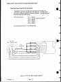
CONSTRUCTION OF SIX-PIN IFB / ISO CABLES
The diagram in Figure 2-12 will help in constructing the six-pin cable. We
recommend a cable with 4 shielded pairs of 22 gauge wire. The cable should
have low DC resistance (less than 15 ohms per 1000 feet). This cable wiring can
be used for both IFB and ISO service.
IFB Connector Pinout
Pin-1 -- Ground
Pin-2 -- +30 VDC (unused by MS-81 2)
Pin-3
Pin-4
Pin-5
IFB Ch 1
IFB Ch 2
-- IFS Ch 3
---
Pin-6-- IFS Ch 4
The recommended cable is a 4 pair shielded cable.
6. PIN
IFB CONNECTOR
4
I
_
2
Figure 2-12 6-PIN IFB CABLE WIRING DIAGRAM
11 /90 Rev. 1.0
Page 2-14
INSTALLATION / Clear-Com MS-812 Programmable Master Station
2.6 CONNECTION TO IS0-4000 SYSTEM
Unless ordered with one of the options listed below the MS-812 is shipped with a blank
plate over holes for four XLR connectors. The ISO-1 6 Option provides two XLR-6M IFB
connectors for eight channels of IFB and two other XLRs for ISO system connection.
The ISO connectors provided are one XLR-6M (ISO Control) and one XLR-3M (ISO
Audio). The following is a description of the options available. No extra Line Driver
modules are necessary for ISO operation. Once configured the MS-812 will directly
control the ISO-4000 ISO system allowing the MS-812 to emulate a up to four ICP-4
control modules. The XLR-3M connector provides a control signal from the ISO-4000
causing a audio interrupt in the MS-812 placing it in anl isolated conversation through the
ISO system.
ISO-16 -- is an option that provides just the rear panel connectors installed for
IFB and ISO operation.
CABLING For ISO control use a 6-pin XLR cable wired as for IFB (see previous page).
For ISO Audio use a single pair shielded cable identical to that used for Clear-Com
intercom lines.
ISO Connector Pinout
Pin-I -- Ground
Pin-2 -- +30 VDC (unused by MS-812)
Pin-3 -- Serial Data from MS-812
Pin-4 -- Serial Clock from ISO-4000
Pin-5 -- Serial Data from ISO-4000
Pin-6 -- Reset Signal from ISO-4000
ISO Audio Connector Pinout
Pin-1
Pin-2
Pin-3
-- Ground
-- Interrupt
Control (+15 VDC Signal)
Audio
-- ISO
CAMERAS
ISO AUDIO/TRANSFER
VIDEO
*
II|fl
111111
~ ~ ~[000
~~,s-400
CP-4
i
izom
tISO AUDIO/
~~TRANSFER0
PARTYLINE INTERCOM
.
COD:
ISO CONTROL_
IS UO/TRANSFER
offs 00
-oI
000
d
o
DIRECTOR
0 aI0O
CONTROL
Typical ISO Installation Figure 2-13
11/90 Rev. 1.0
Page 2-15
z
0
INSTALLATION / Clear-Com MS-812 Programmable Master Station
F~~~~~~~~~~~
.80
C
CE"-
C
-1R
a
K?=5-11
~iiBIT
a
SWITCHES
ENABLE SA FEEDX
GLOBAL RELAY 1-49
0G
L1
IFS 5-5--C
EAR
I F~~~LFT
C7)
IFB
PGM
-
~
U.C=)
~
PGM
-
1
SPEAKER
INTERCOM 9-12
.Ot~~
-
INTERCOM 5-5-
It60
2.2
4
INTERCOM 1-4~
1
-
0;
1,9
Z
Re 0
z
z
r
-
a
m
m
2
wr
H
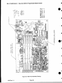
Location of Main Board Option Switches and Jumpers
Figure 2-14
11i90
Rev- 1.0
ISO SIDETONE
Page 2-16
J•D
PANEL MIC GAIN
0
INSTALLATION / Clear-Com MS-812 Programmable Master Station
a
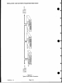
2.7 INTERNAL OPTIONS
There are a number of internal option switches and jumper located on the main PCB in
the MS-812. To access these jumpers and switches remove the top cover of the unit.
Refer to the diagram on the previous page for location of these options.
2.7.1 OPTIONAL PROGRAM #1 FEED TO SPEAKER (Default - ON)
As shipped from the factory Program #1 input will feed both Intercom program
feed and Program listen on the Speaker and Headphones. If a second program
feed is used (available on the DB-15 connector) remove the jump jack on J32 to
remove Program #1 from the Speaker and Headphone feed.
2.7.2 OPTIONAL PROGRAM FEED TO LEFT EAR (Default - ON)
As shipped form the factory the MS-812 is intended for use with a Monaural
headphone through the front panel headphone jack. If a stereo headphone is
connected through the DB-15, it is usually desirable that Intercom be in one ear
while Program be in the other. Remove the jump jack on J34 to remove program
from the left ear.
2.7.3 OPTIONAL GLOBAL SA FEED TO ELCO/EDAC CONNECTORS (Default - OFF)
If the ELCO mufti-pair cable rear panel connector option is used the SA signal
would be available in that cable. The SA feed to this cable must be enabled
using jumper J33. As this line is a bridging bus similar to Clear-Com intercom
lines itneeds to be terminated.
00
As shipped from the factory a jump jack is connected between pins 1 and 2
placing a termination on the line driver and removing the feed from the ELCO
cable. To enable this function remove the jump jack from pins 1 and 2, and
place it on pins 2 and 3.
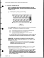
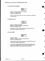
2.7.4 DIP SWITCH PROGRAM OPTIONS (Default - ALL OFF)
The microprocessor program for the MS-812 has several options that are
selectable by the user. As shipped from the factory all DIP switches are placed
in the off position. The following chart shows the basic purpose of the switches:
1. MULTIPLE SETUP ENABLE
OFF-Disabled
2. MENU LEVEL SELECT
OFF-Basic
OFF-Disabled
3. BUTTON LOCK (Menu) ON/OFF
OFF-Disabled
4. IFB MENU ENABLE (PIC-4000)
5. ISO MENU ENABLE (IS0-4000)
OFF-Disabled
6. not used
OFF-Normal
7. REVERSE TALK/LISTEN
8. FACTORY TEST - MUST BE IN OFF POSITION
Unit will appear to malfunction if ON.
6/91 Rev. 1.1
Page 2-17
ON-Enabled
ON-Extended
ON-Enabled
ON-Enabled
ON-Enabled
ON-Reverse
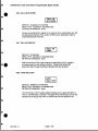
INSTALLATION / Clear-Com MS-812 Programmable Master Station
DIP switches 3 - 5 only affect the availability of the respective menus however
the actual function could operate if the particular program option had been set
before the DIP switch is placed in the off position.
S
Example: With DIP SW #3 in the ON position, certain front panel buttons could
be set permanently ON. The DIP SW could then be set to OFF but the particular
buttons would be locked ON but the user could not change it.
S
An internal DIP Switch option allows the reversal of the TALK and LISTEN buttons on the front panel. DIP SW #7 places the LISTEN buttons on the bottom
row and the TALK buttons on the top row. All programmed options will track their
appropriate buttons.
Channel number assignment for IFB and ISO are also swapped. Channel #1
would now be on the bottom row. (Section 4.6.19 explains the normal channel
numbering scheme.) The same examples in the REVERSE mode are as follows:
2
1
334
12
456
1 2 3
S
5678
1234
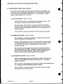
2.8 CONNECT MS-812 INTERCOM STATION TO A SOURCE OF A.C.
POWER
The Station is typically shipped configured for the country of installation. The internal
110/220 VAC switch (located inside the chassis) allows configuration for locally available
line voltage.
*
To access the internal 110/220 VAC switch, unplug the AC power cord. Then, unscrew
and remove the top cover of the Intercom Station. The switch is located on top of the AC
connector block inside the chassis and is labeled "110/220."
THE FUSE MUST BE CHANGED:
0
--11OV uses 0.5A slow-blow
--220V uses 0.25A slow-blow
Remember to also replace the original spare fuse (located in the fuse holder) with one
that matches the voltage setup.
0
Plug the power cord extending from the Intercom Station's rear panel into a source of AC
power.
.RPe
6/91 Rev. 1.1
Page 2-18
SETUP & ADJUSTMENT I Clear-Com MS-812 Programmable Master Station
SECTION 3
SETUP & ADJUSTMENT OF THE MS-812 PROGRAMMABLE MASTER INTERCOM STATION
3.1 INTERNAL OPTIONS
There are a number of internal option switches and jumper located on the main PCB in
the MS-812. To access these jumpers and switches remove the top cover of the unit.
Refer to the diagram on the page 2-16 for location of these options.
3.1.1 OPTIONAL PROGRAM #1 FEED TO SPEAKER (Default - ON)
As shipped from the factory, Program #1 input will feed both Intercom program
feed and Program listen on the Speaker and Headphones. If a second program
feed is used, (available on the DB-15 connector) remove the jump jack on J32 to
remove Program #1 from the Speaker and Headphone feed.
3.1.2 OPTIONAL PROGRAM FEED TO LEFT EAR (Default - ON)
As shipped form the factory the MS-812 is intended for use with a monaural
headphone through the front panel headphone jack. If a stereo headphone is
connected through the DB-15, it is usually desirable that Intercom be in one ear
while Program be in the other. Remove the jump jack on J34 to remove program
from the left ear.
3.1.3 OPTIONAL GLOBAL SA FEED TO ELCO/EDAC CONNECTORS (Default - OFF)
If the ELCO multi-pair cable rear panel connector option is used, the SA signal
would be available in that cable. The SA feed to this cable must be enabled
using jumper J33. As this line is a bridging bus similar to Clear-Com intercom
lines it needs to be terminated. As shipped from the factory a jump jack is
connected between pins 1 and 2 placing a termination on the line driver and
removing the feed from the ELCO cable. To enable this function remove the
jump jack from pins 1 and 2, and place it on pins 2 and 3.
3.1.4 DIP SWITCH PROGRAM OPTIONS (Defaut - ALL OFF)
The microprocessor program for the MS-812 has several options that are
selectable by the user. As shipped from the factory all DIP switches are placed in
the off position. The following chart shows the basic purpose of the switches:
1. MULTIPLE SETUP ENABLE
OFF-Disabled
2. MENU LEVEL SELECT
OFF-Basic
3. BUTTON LOCK (Menu) ON/OFF
OFF-Disabled
4. IFB MENU ENABLE (PIC-4000)
OFF-Disabled
5. ISO MENU ENABLE (ISO-4000)
OFF-Disabled
6. not used
7. REVERSE TALK/LISTEN
OFF-Normal
8. FACTORY TEST - MUST BE IN OFF POSITION
Unit will appear to malfunction if ON.
ON-Enabled
ON-Extended
ON-Enabled
ON-Enabled
ON-Enabled
ON-Reverse
Example: With DIP SW #3 in the ON position, certain front panel buttons
could be set permanently ON. The DIP SW could then be set to OFF but
the particular buttons would be locked ON but the user could not change
it from the front panel.
6191 Rev. 1.1
Page 3-1
SETUP & ADJUSTMENT / Clear-Com MS-81 2 Programmable Master Station
3.1.5 AC VOLTAGE SELECTION
The Station is typically shipped configured for the country of installation. The
internal 11 0/220 VAC switch (located inside the chassis) lets you reconfigure for
the local line voltage.
To access the internal 11 0/220 VAC switch, unplug the AC power cord. Then,
unscrew and remove the top cover of the Intercom Station. The switch is located
on top of the AC connector block inside the chassis and is labeled "110/220."
You also must change the fuse: --11OV uses 0.5A slow-blow
--220V uses 0.25A slow-blow
Remember to also replace the original spare fuse (located in the fuse holder)
with one that matches your setup.
3.2 INTERNAL ADJUSTMENTS
There are very few internal adjustments in the MS-81 2.
3.2.1 PANEL MICROPHONE GAIN TRIM
The Panel Microphone gain can be adjusted for a particular person or environment
that the station is being used. In a high noise environment the gain should be set
low causing the operator to work the microphone closely and thereby reducing
the influence of background noise. Some installations require that the operator
work the microphone from a distance, in this case the gain should be set high.
The gain of the microphone preamplifier is adjustable when it is switched to the
Panel Microphone. Potentiometer, P1, allows a +/- 5 dB adjustment in gain. See
figure 3-1 for location of this control.
3.2.2 INTERCOM LINE NULL (SIDETONE) ADJUSTMENT
SIDETONE is the amount you hear yourself in your own headset. In headsets
a controlled amount of sidetone is desirable for assurance that the microphone
is on. Sidetone in a speaker can cause feedback and is not desirable.
The MS-812 has a front panel SIDETONE control that sets the amount of LOCAL
sidetone heard in the headphone.
The Line Driver circuitry consists of a hybrid null circuit that attempts to reject all
of the TALK signal being sent to the intercom line. The rejection (NULL) circuit
compares the intercom line with the send (TALK) signal. The balance of this
circuit depends on the impedance of the intercom line to be stable. The NULL
adjustment control compensates for variations in line impedance due to various
amounts of cable and numbers of stations on the line. A mis-adjusted NULL
control on a line driver will cause extra sidetone in the headphone that is not
controllable on the front panel. The ideal setup is to have no sidetone from the
line driver, therefore the only sidetone heard is that inserted by the front panel
trim control. Excessive sidetone in the speaker will cause feedback.
(continued)
11/90 Rev. 1.0
Page 3-2
SETUP & ADJUSTMENT / Clear-Com MS-812 Programmable Master Station
*
NULL ADJUSTMENT OF LINE DRIVERS: Each intercom Line Driver circuit has a
NULL control allowing it to be matched to impedance of the particular intercom
line it is connected to. As shipped from the factory, the NULL control has been
set for a Clear-Com line of 200 feet which will produce acceptable results for
lines from 0 to 500 feet. For optimum results with these short lines or use of
longer lines follow the following procedure for NULL trimming:
1. Remove the top cover of the MS-812.
2. Turn the LOCAL SIDETONE trim control on the front panel fully oft.
3. Make sure that the line to be nulled to is configured as it will be in normal use
including termination.
3. With the front panel pushbuttons, set a TALK and LISTEN only to the
channel being nulled.
4. Using a headset, talk into the microphone and listen to the sidetone in the
headphone.
5. Adjust the NULL control for the particular channel for a minimum sidetone
(null). Refer to figure 3-2 for location of the controls. Only the twelve
intercom channels need to be nulled. The IFB Line Drivers only drive the line
and the listen circuits are not used. Select another channel and repeat the
procedure.
6. If an ISO system is installed the ISO null control will also need adjustment.
Using a front panel button that has been programmed for ISO, activate ISO
such that the sidetone from the ISO line can be heard in the headphone.
Adjust the ISO null control for minimum sidetone. Refer to figure 3-2 for
location of this control.
*
*
*
0~~~~~~~~~~~~~~~~~~
a
LS-e812 MAiN BOARD
W®J-
*
p2>
FELS
eJ-
LA;
p^Lx
9
S CHANNELS 5-8
p
C~~~~~~~~fl
-,~~~~~.
1-4
~~~9-12
1-4
*
L;L4
*
~
<2>
L)#UANNELN5-8
Figure 3.1 Null Adjustment of Line Drivers
11/90 Rev. 1.0
Page 3-3
OPERATION / Clear-Com MS-812 Programmable Master Station
SECTION 4 / OPERATION OF THE MS-812 PROGRAMMABLE MASTER INTERCOM STATION
The MS-812 is a mufti-channel intercom station with the exact function of front panel
controls being definable by the user. As shipped from the factory, all programming
options are set for default settings. With default settings the station will function as a
simple 12 channel intercom. Special functions such as IFB, ISO, and RELAY activation
will need to be programmed.
SETUP MEMORY: The configuration or SETUP of the station is saved in NVM (NonVolatile Memory) such that the SETUP is saved during power-down. There are four
complete setups saved. Each SETUP is a complete personality for the machine.
KEY ACTION: All illuminated buttons are dual action. If pressed for a short period of
time (less than 1/4 second) the button will "LATCH" when released. If pressed longer,
the button will be momentary. IXl button Ea z= illuminated when the function ji o
Latching action can be disabled on certain buttons through the LATCH DISABLE function
in the programming mode.
BUTTON FUNCTION TYPE: Because the station is programmable the fundamental way
a button works can be different. Besides the special function buttons such as MIC ON,
PANEL MIC ON, SPKR ON, CALL, and SA, the buttons can be programmed to five
distinct types of functions: (NOTE: Because the 24 selector buttons "default" to intercom
functions, they are referred to as "TALK" and "LISTEN" buttons.)
INTERCOM Operation: Intercom operation is the default type for all
TALK/LISTEN buttons. In INTERCOM mode the bottom row of buttons are for TALK
activation and the top row are for LISTEN activation. Incoming CALL signals will
flash the appropriate LISTEN button.
IFB Operation: TALK/LISTEN buttons can be programed to function as IFB
channels directly controlling a CC PIC-4000 IFB system. In this mode the normal
intercom channel that the particular button would have talked or listened to is
non-functional at this station. The button only controls a TALK to a particular IFB
channel and automatically sends a CALL signal activating the PIC-4000 IFB
controller. IFB tally will flash the appropriate IFB channel.
The IFB function can be programmed as a PRIVATE TALK function. During
PRIVATE TALK, all other intercom talk paths are momentarily disabled. The
default of the IFB function allows communications on all other intercom talk paths
to continue.
ISO Operation: TALK/LISTEN buttons can be programed to function as ISO
channels thereby directly controlling a Clear-Com ISO-4000 system. In this
mode the normal intercom channel that the particular button would have talked or
listened to is now non-functional at this station. The button only controls a
combined TALK and LISTEN directly to the ISO system. Control signals are sent
to the IS04000 to instruct it to place a particular station on an isolated intercom
path to the MS-81 2.
By default, the ISO function is a PRIVATE TALK function, all other TALK Paths
are momentarily disabled during the ISO operation. The button can be programmed to allow communications on all other intercom talk paths to continue.
(ISO Operation continued)
6/91 Rev. 1.1
Page 4-1
OPERATION / Clear-Com MS-812 Programmable Master Station
0
(ISO Operation continued)
By default, the ISO function is also a PRIVATE LISTEN Function, all other LISTEN
Paths are momentarily disabled during the ISO operation. The button can be
programmed for Normal Listen.
RELAY ONLY Operation: If a button has no other assigned purpose but has
a relay assigned, it will become a RELAY ONLY button operating no other
function than the relay assigned to it. If all of the Line Driver Modules are not
installed and the buttons that are associated with the missing module is not
programmed to ISO or IFB the button would have no purpose. It might be
desirable to program such a button for just relay activation. An unassigned
PRESET button will also fall into this category.
It is important to remember that buttons can be programmed to operate nothing
but relays. If pressing such a button and no apparent action at the station results
it must be remembered that the button may be activating a GLOBAL RELAY
located some where else. A reading of the BUTTON CHECK function would
reveal this operation.
PRESET OPERATION: The PRESET buttons are a special type of button.
Normally other buttons are assigned to the PRESETs and their function is to
operate those other buttons as if they were pressed. The logical action of
PRESETs can be ADDITIVE or INTERLOCKING, (see PRESET button
descriptions). If a preset becomes a RELAY ONLY button it will no longer follow
the INTERLOCKING logic of a normal PRESET button.
*
PRIORITY, PRIORITY TALLY, and PRIORITY OVERRIDE
The major functions such as SA, IFB, ISO have a predetermined priority. Because these
functions are exclusive, interrupt or replace existing station activity, they have been
assigned levels of priority based on their importance. In general, priorities are logical,
automatic and transparent to the operator. The priority sequence is as follows:
1.
2.
3.
4.
5.
SA
IFB
ISO
Private Intercom Listen/Talk
Normal Intercom activity
0
S
EXAMPLE: If a button is set for PRIVATE TALK it will interrupt other TALKs when i is
activated; however, pressing an IFB button will interrupt the PRIVATE TALK function.
Priorities are not in effect inside a PRESET or FOOTSWITCH assignment. EXAMPLE:
If a button set for ISO and the SA button are both placed in the same PRESET, then both
functions will operate.
PRIORITY TALLY: If a higher priority function overrides a lower level function the lower
level's button will flash at a special rate (short on-long off) indicating that the function has
been temporarily overridden.
S
PRIORITY OVERRIDE: If a button has been overridden by a higher priority function and
it is desired to still TALK or LISTEN to the channel, simply press that button and the
function will return.
0
11/90 Rev. 1.0
Page 4-2
OPERATION / Clear-Com MS-812 Programmable Master Station
*
4.1 LCD DISPLAY
The MS-812 features a LCD display intended to guide the user in programming the
station. The rest of this text will show actual displays in the context that they apply.
PROGRAMMING MODE: During programming the LCD display shows the current menu
item by name.
NORMAL OPERATION: During normal operation the display shows the current SETUP
name. These names are programmable by the user (refer section 4.6.23). If during
normal operation, a button is pressed that causes an error a BEEP tone will be issued
and the display will show one of two messages:
BUTTON
BUTTON
IINACTIV
LOCKE:D
BUTTON INACTIVE: This error message indicates that a button was pressed
that currently has no function. If the line driver module necessary to support a
particular channel is not installed in the unh then this error will result. If a button
is programmed for ISO and an active ISO system is not connected to the unit the
same error will result. If a PRESET button has no buttons or relays assigned,
the same error will result.
BUTTON LOCKED Pressing a key that has been locked ON or OFF, in the
programming mode, will produce this error.
0~~~~~~~~~~~~~~~~~~~~0
\W
\Of\
L
\X \ O \~~~~?
0
Figure 4-1 Front Panel Description
11/90 Rev. 1.0
Page 4-3
OPERATION I Clear-Com MS-812 Programmable Master Station
4.2 DESCRIPTION OF FRONT PANEL BUTTONS
Most of the front panel buttons on the MS-812 are illuminated and re-legendable. The
illumination is dim for indicating OFF and bright for ON. Overall brightness is adjustable
by a front panel trim control (LAMP BRIGHTNESS). In normal operation, a flashing
button is a tally indication (CALL, IFB or ISO).
4.2.1 'MIC ON' BUTTON -- Figure 4-1 item #1
The MIC ON button turns on or off audio from the microphone pre-amp. A MIC
ON condition is indicated by bright illumination of the button.
If the microphone is turned off and a TALK path is requested by other button
action at the station, the microphone automatically turns on. If the function was a
momentary function the microphone will return to the OFF condition when the
function is released.
The MIC ON/OFF control does not affect the HOT MIC output from the station.
4.2.2 'PANEL MIC' BUTTON -- Figure 4-1 hem #2
When a HEADSET is connected to the MS-812 the PANEL MIC button selects
either the PANEL MIC or the HEADSET MIC.
Without a headset plugged into the unit the Panel microphone is always selected,
the PANEL MIC button will be illuminated, and the button will not operate, (there
is no HEADSET MIC to select). An illuminated button indicates Panel
microphone operation.
When a headset is initially plugged into the station the microphone pre-amp is
automatically switched to headset. Unplugging a headset automatically returns
the unit to Panel microphone operation. When a headset is plugged in the
PANEL MIC button is used to select between the two microphones.
4.2.3 'SPEAKER ON' BUTTON -- Figure 4-1 item #3
Without a headset plugged into the unit, the Speaker is always on and cannot be
shut off. An illuminated button indicates that the speaker is on. The headset
earphone is always on.
When a headset is initially plugged into the station, the speaker is automatically turned
off. Unplugging a headset automatically enables the speaker.
When a HEADSET is connected to MS-812 the SPEAKER ON button enables
the SPEAKER to be turned ON and OFF.
11/90 Rev. 1.0
Page 4-4
OPERATION / Clear-Com MS-812 Programmable Master Station
4.2.4 'PRESET' BUTTONS -- Figure 4-1 item #6
Four special function buttons called PRESETs can be programmed by the user
to activate any combination of the 24 selector buttons and the SA button. Refer
to section 4.6.1 for instructions on programming these buttons.
If a PRESET button is programmed to particular buttons, when pressed those
functions will be activated just as if they were pressed all at the same time.
The logical action of the PRESET buttons is selectable in the programming
mode. The choice of modes is the same for all preset buttons. Refer to Section
4.6.2.
INTERLOCK: If a preset is active and another preset button is
pressed the second preset functions will replace the first. If the second
button press is momentary in duration the original active preset will
return when the second one is released. If the second preset is latching,
releasing it will return the station to no preset activity.
ADDITIVE: In this mode multiple presets will simply add functions to
what is already active. Removing a preset in this mode will only remove
those functions added by that preset.
4.2.5 'CALL' BUTTON -- Figure 4-1 item #7
The CALL button is used to enable sending a CALL to the intercom lines (ft does
not directly send a CALL signal). Pressing CALL enables the CALL function and
illuminates the button. Pressing a TALK key while the CALL button is illuminated
will send a CALL signal on that intercom line. The CALL function will time-out
and turn itself off if it is not used for 3 seconds.
4.2.6 'SA' BUTTON -- Figure 4-1 hem #8
The SA button is used to activate the Stage Announce output of the station. It
pressed in normal operation, all active TALKs will turn off and the microphone
pre-amp output will be routed to the SA output. The SA button is default
programmed for PRIVATE LISTEN which can be disabled if normal Listens are
desired. If SA has been assigned to a PRESET button it will not affect the other
TALKs and LISTENs set to the PRESET.
If a contact closure is desired when the SA button is pressed, one of the local or
global relays would need to be programmed to the button.
The SA button is default programmed for LATCH DISABLE making it
momentary. If desired, latching action can be restored using the Latch Disable
menu in the programming mode.
11/90 Rev. 1.0
Page 4-5
OPERATION / Clear-Com MS-812 Programmable Master Station
4.2.7 'TALK' and 'LISTEN' BUTTONS -- Figure 4-1 items #4 and #14
INTERCOM USE: The top row (item #4) of the twenty four buttons in the middle
of the station are used to turn on LISTENs to an intercom channel. The
bottom row of buttons (item #14) turns on TALKs to the corresponding
intercom channel.
Incoming call signals will flash the appropriate Listen button, If CALL-IN on a
particular channel is enabled. As shipped from the factory all call-in
signaling is enabled.
e
Sending of call signals is accomplished by enabling the CALL send mode
with the CALL button and then pressing the appropriate TALK button.
S
IFB and ISO USE: Groups of buttons can be programmed for control of IFB or
ISO channels if desired. When programmed for these functions the normal
TALKs and LISTENs for the particular channel are lost to the user.
Example: If channels 11 and 12 are programmed for IFB, intercom
channels 11 and 12 are no longer active at this station.
4.2.8 "NEXT (V)' and "BACK (A)" PROGRAM BUTTONS -- Figure 4-1 items #16 and #18
The two black pushbuttons located just below the LCD display, marked "V"
(NEXT) and "A" (BACK) are intended primarily for programming purposes.
During normal operation these buttons have special functions. The terms NEXT
and BACK will be used in the following text.
@0
4.2.8.1 SELECTING SETUPS "NEXT (V)"
In normal operation the NEXT (V) button is used to select other system
setups. Pressing and holding the NEXT (V) button for one second brings up
a special menu allowing the user to select one of the four SETUPS
saved in memory. The LCD display will respond as follows:
S
Select
setup
S
l
The four PRESET buttons will now flash except for the one representing
the current SETUP number, which will be on steady. Pressing any of the
four buttons will select that SETUP and immediately exit the mode.
Setup selection can be disabled via an internal DIP switch (refer to
page 4-10).
.RPg
11/90 Rev. 1.0
Page 4-6
OPERATION / Clear-Com MS-812 Programmable Master Station
4.2.8.2 BUTTON CHECK FUNCTION (BACK (A))
.0
In normal operation the BACK (A) button is used to enable the BUTTON
CHECK function. Pressing and holding the BACK (A) key for one
second will place the system in BUTTON CHECK mode. The LCD display will respond:
Button
I Check
All illuminated buttons will now flash indicating that they are available for
inquiry about their status. Pressing any one of the buttons will cause the
LCD display to indicate "Button Type", "Status", and then list all functions
that button is programmed to. To exit a particular button check inquiry
before it is finished, press the button again.
Button Types: INTERCOM
IFB
ISO
PRESET
RLY ONLY
Status Types: No Audio Card
No ISO System
Preset Empty
If the RESET button is pressed while in the BUTTON CHECK mode, the
display will present special infomiation about the unit. The display will
sequence between three different screens:
0
A.
software
X. |
|Rev
Displays the Revision level of the software in the machine.
B.
I Dip
Sw.
i xxxmXxxX I
Displays the setting of the internal DIP switches. '0' = OFF '1' = ON
C.
Standard
Talk/Lsn
Reverse
Ialk/Lsn
Displays the orientation of the TALK/LISTEN buttons.
6/91 Rev. 1.1
Page 4-7A
OPERATION / Clear-Com MS-812 Programmable Master Station
4.2.8.3 ACCESSING PROGRAMMING MODE
Pressing and holding NEXT (V) and BACK (A) together for one second
will display the word "Menu" on the screen, and cause the system to
enter the programming mode. Releasing and pressing both buttons
again will cause the system to access the EXTENDED MENU if enabled.
Refer to section 4.5 for information on programming.
4.2.8.4 STEPPING THROUGH MENUS
When the system is in the programming mode the NEXT (V) and BACK
(A) buttons enable stepping through the menus. Pressing and releasing
NEXT (V) steps forward in the menus while pressing and releasing
BACK (A) steps backward in the menus. Refer to section 4.5 for information on programming.
4.2.9 'RESET' BUTTON -- Figure 4-1 htem #17
There is a small unmarked hole between the NEXT (V) and BACK (A) buttons
that provides access to a RESET button. A small screwdriver can be used to
depress this button. The action of the RESET button depends on the operating
mode at the time.
NORMAL OPERATION: (RESET Current SETUP) If the RESET button
is pressed during normal operation, all the buttons will flash as a warning
and the LCD display will show "RESET" with a series of arrows on the
bottom row progressing across the screen. After four seconds the bottom
row of the screen will be filled with arrows and then the system will RESET
only the current SETUP. Ali programmed options will be reset to DEFAULT
conditions except for current setup name and ISO Station Number.
6/91 Rev. 1.1
Page 4-7B
OPERATION / Clear-Com MS-812 Programmable Master Station
(RESET continued)
PROGRAMMING MODE: (RESET Selected Menu Item) If the RESET
button is pressed while in the Programming Mode, the currently selected
menu item will be set to its default setting.
POWER UP RESET: (Complete Memory Clear) If the RESET button is
depressed while the AC power isturned on, the system will completely reset
all four SETUPS to (Factory) Defaults. This RESET mode should only be
used to totally clear the machine.
4.3 DESCRIPTION OF FRONT PANEL CONTROLS
4.3.1 PROGRAM VOLUME -- Figure 4-1 item #9
The PROGRAM VOLUME control sets the amount of external program heard in
the speaker and headphones.
4.3.2 INTERCOM VOLUME -- Figure 4-1 item #11
The INTERCOM VOLUME control sets the overall Listen level of the intercom
lines. Each of the twelve intercom lines also have a Listen level trim control
located under each of the respective TALK buttons.
4.3.3 PROGRAM FEED Trim Level -- Figure 4-1 item #5
0
The PGM FEED trim control sets the amount of Program being sent to Intercom
lines.
4.3.4 SPEAKER MUTE TRIM LEVEL -- Figure 4-1 item #15
If the Panel microphone and the Speaker are both enabled at the same time
there isthe possibility of feedback. During this mode the audio level to the
speaker can be reduced (Muted) to prevent this feedback. The amount of
reduction is set by the SPKR MUTE trim level control.
4.3.5 SIDETONE LEVEL TRIM (LOCAL) -- Figure 4-1 item #15
Sidetone is the portion of the local headset microphone signal that is also heard
in the earphone. This effect is desirable as a confidence factor that the
microphone is operating. The SIDE TONE trim control adjusts the amount of
locally generated sidetone.
NOTE: Side tone can also be generated by an improperly nulled
intercom line driver. The Local Sidetone Control will have no effect on
this source of side tone. Refer to section 3.2.2 for sidetone null adjustment
of intercom line drivers.
11/90 Rev. 1.0
Page 4-8
OPERATION / Clear-Com MS-812 Programmable Master Station
4.3.6 BEEP TONE LEVEL TRIM -- Figure 4-1 item #15
BEEP tones are generated at various times in the operation of the system.
These tones are only heard in the Speaker and are not affected by the Intercom
Volume control. The BEEP tone is only affected by the SPEAKER ON/OFF
button and the BEEP LEVEL trim control. Adjust the BEEP LEVEL trim control
for desired level.
4.3.7 LAMP BRIGHTNESS -- Figure 4-1 Rem #15
The overall brightness of the illuminated buttons is controlled by the LAMP
BRIGHTNESS trim control. It simultaneously adjust both the "Dim" (OFF) and
"Bright" (ON) intensity.
4.3.8 LISTEN LEVEL TRIMS -- Figure 4-1 item #13
The INTERCOM VOLUME control sets the overall Listen level of the 12 intercom
channels. Each of the twelve intercom channels also have LISTEN TRIM
controls located under each of the respective TALK buttons.
These LISTEN TRIM controls allow the individual level adjustment of each
intercom channel. These controls only have a range of 20 dB. The fully clockwise position of the controls is the normal listen level.
0
4.4 HEADSET CONNECTOR
The HEADSET CONNECTOR allows the user to connect a mono headset directly in the
front panel. The presence of a headset is sensed by the systems microprocessor.
Connecting a headset will cause the station to automatically switch to the headset
microphone and turn the speaker off. Disconnecting a headset will cause the station to
switch to the Panel microphone and enable speaker operation.
While a headset is connected it is possible to select microphones and turn the speaker
on and off with the PANEL MIC button and SPEAKER ON button.
If this connector is not used but the rear panel access of the headset circuit is used to
bring the headset connector out to some other location other than the front panel, the
presence of a headset will still be sensed and the station will operate as if the headset
were plugged into the front panel connector.
11/90 Rev. 1.0
Page 4-9
OPERATION / Clear-Com MS-812 Programmable Master Station
4.5 STATION PROGRAMMING
A major feature of the MS-812 is that the function and attributes of front panel buttons
can be defined by the user. Multiple versions (four) of these setups can be saved in NonVolatile Memory that is secure during power down of the station.
The LCD display guides the user through multiple menus for programming. Two different
levels of menus are available.
Once in the Programming Mode the NEXT (V) and BACK (A) buttons are used for stepping from
menu to menu. In a given menu function, buttons that are available to be programmed to
the particular function are Flashing. Buttons whose lamps are on solid are programmed
for that function. Buttons whose lamps are off are not available for the function. Some
functions interact; example -- An intercom channel cannot be programmed for program
interrupt unless its program feed is enabled -- A button that is LOCKED OFF cannot be
LOCKED ON.
If a particular menu item is a Sub-Menu the SA button will flash. Pressing the SA button
will g=ntLI availability of items inside the Sub-Menu. Going on to the next menu item
whhout pressing SA will skip all of the Sub-Menu items.
NORMAL MENU: Once a station is setup, the day-to-day operation of the machine
usually will not require all of the programming features available. A shortened
version of the programming menu provides quick access to the menu items that are
most used.
(ENTER PGM MODE)
4
t
Li
--
-
PRESET #1 -----------PRESET #2 -----------PRESET #3 -----------PRESET #4 -----------ENABLE CALL-IN ------CALL-IN BEEP --------PROGRAM FEED --------PROGRAM INTERRUPT ----
Select
Select
Select
Select
Enable
Enable
Enable
Enable
ACTION
Keys for PRESET #1
Keys for PRESET #2
Keys for PRESET #3
Keys for PRESET #4
CALL-IN for Intercom Channels
Audible BEEP with CALL-IN
PROGRAM FEEDS
PROGRAM INTERRUPTS
Figure 4-2 Normal Menu
EXTENDED MENU: To support very sophisticated use of the MS-812, an
extended version of the programming menu is provided. In the extended menu
some of the subjects have been grouped into sub-menus. Some of the menu items
that support special features of the MS-812 can be turned off by internal DIP
switches so that these menu items will not be displayed if the feature is not used.
The DIP switches only affect the availability of the menus but do not affect the
operation of the station. The following is description of the DIP switches.
1. MULTIPLE SETUP MENU ENABLE This DIP switch only enables the access
of the multiple SETUP menu.
2. EXTENDED MENU ENABLE
3. BUTTON LOCK ON/OFF MENU ENABLE
4. IFB BUTTON ASSIGNMENT MENU ENABLE
5. ISO BUTTON ASSIGNMENT MENU ENABLE
11/90 Rev. 1.0
Page 4-10
OPERATION / Clear-Com MS-812 Programmable Master Station
EXTENDED MENU
-
(ENTER PGM MODE)
4f
ACTION
SA BUTTON)
-fPreset Submenu - - - -(FLASHING
Buttons for PRESET
Select
-PRESET #1 ---------Buttons for PRESET
Select
R-PRESET #2 ---------Buttons for PRESET
Select
-- PRESET #3 ---------Buttons for PRESET
Select
F-PRESET #4 ---------or INTERLOC Mode
ADDITIVE
-L~PRESETS: (Operation)
.
FOOT SWITCH ----------
#1
#2
#3
#4
Select
Select Buttons for FOOT SWITCH Activation
SA BUTTON)
-. Call Sig Submenu - - -(FLASHING
for INTERCOM Channels
CALL-IN
Enable
- ENABLE CALL-IN ----CALL-IN
on
BEEP
Enable
------LL-IN BEEP
LISTEN on CALL-IN
and/or
TALK
Enable
L-IN ACTIVATE --TIME-OUT
CALL-IN
of
Length
Set
L-IN TIME: -----CALL-OUT
Automatic
for
Buttons
Select
- AUTO CALL-OUT -----0
- PROGRAM FEED --------INTERRUPT ----PROGRAM
Enable PROGRAM FEEDS
Enable PROGRAM INTERRUPTS
-Relay Submenu - - - - RELAY #1 -----LOCAL
RELAY #2 -----LOCAL
GLOBAL RELAY #1 ---RELAY #2 ----GLOBAL
-1 GLOBAL RELAY #3 ---GLOBAL RELAY #4 ----
(FLASHING
Select
Select
Select
Select
Select
Select
PRIVATE TALK --------PRIVATE LISTEN ------W/TALK --------LISTEN
DISABLE --------LATCH
-*-BUTTON LOCK OFF ------*-BUTTON LOCK ON ------EXCLUDE -------PRESET
-*-SET IFB BUTTONS -----4*ISO Submenu - - - - - -SET ISO BUTTONS ---- ISO STA #: --------ISO 1ST CHA #: ----.4
-RENAME
t
(*)
--
SETUP ---------
for
for
for
for
for
for
LOCAL RELAY #1
LOCAL RELAY #2
GLOBAL RELAY #1
GLOBAL RELAY #2
GLOBAL RELAY #3
GLOBAL RELAY #4
Select TALK Buttons for PRIVATE TALK
Select LISTEN Buttons for PRIVATE LISTEN
Select AUTO-LISTEN with TALK Button
Disable LATCHING of a Button
Select Buttons to be Locked 'OFF'
Select Buttons to be Locked 'ON'
Select Buttons to EXCLUDE from PRESET
Select/Position Buttons for IFB Function
(FLASHING SA KEY)
Select/Position Buttons for ISO Function
Select ISO Control Station #
Select Start Channel x for ISO
Rename Current SETUP
AN INTERNAL DIP SELECT SWITCH ENABLES THIS FUNCTION
Figure 4-3 Extended Menu
6@91 Rev. 1.1
SA KEY)
Buttons
Buttons
Buttons
Buttons
Buttons
Buttons
Page 4-11
OPERATION / Clear-Corn MS-812 Programmable Master Station
4.5.1 ENTERING PROGRAMMING MODE
Pressing and holding NEXT (V) and BACK (A) buttons together for one second
will cause the LCD screen to display "MENU" and enter the programming mode.
While the word "MENU" is displayed, quickly releasing and pressing both buttons
again will cause the station to access the EXTENDED MENU, if it is enabled with
a DIP switch. See section 4.5.
4.5.2 STEPPING THROUGH MENUS
When the system is in the programming mode the NEXT (V) and BACK (A) buttons are
used for stepping through the menus. Pressing and releasing NEXT (V) steps
forward in the menu while pressing and releasing BACK (A) steps backward.
A
4.5.3 SUB-MENU ACCESS
If a 'Sub-Menu' selection is displayed, pressing the flashing SA key at this time
will open a series of related 'Sub-Menu' hems. After pressing the SA button, the
'Sub-Menu' is available with the NEXT (V) button.
A Sub-Menu that has been "opened" will remain "open" during the entire
programming session, even it the particular Sub-Menu is left and then returned
a.
to.
4.5.4 EXITING PROGRAMMING MODE
Pressing both NEXT (V) and BACK (A) buttons together while in any of the
above menus will exit the programming mode, and return the MS-812 to normal
operation.
4.6 DESCRIPTION OF PROGRAMMING MENUS
S
.
The following paragraphs describe each menu function in detail. All NORMAL MENU
items are also in the EXTENDED MODE. In this discussion no distinction is made for
those items found in sub-menus. For a better understanding of the menu organization
refer to the menu trees in figure 4-2 and figure 4-3 on pages 4-10 and 4-11.
S
11/90 Rev. 1.0
Page 4-12
OPERATION / Clear-Com MS-812 Programmable Master Station
0
4.6.1 PRESET ASSIGNMENT
|PRtESET
1
DEFAULT: No buttons programmed to PRESETs.
MENU TYPE: Normal or Sub-Menu in Extended Mode.
DIP SWITCH ENABLING: None
Allows assignment of any combination of the 24 selector buttons and the SA
button to be assigned to, and subsequently activated by, any of the four PRESET
buttons. Use NEXT (V) and BACK (A)to select the PRESET button to be
programmed. Relays are assigned to PRESET buttons with their own menus;
see section 4.6.11.
Other menus that affect the operation of PRESETs are as follows:
-- PRESET OPERATION MODE see section 4.6.2
-- PRESET EXCLUDE see section 4.6.18
4.6.2 PRESET OPERATION MODE
|PRESETS: |
IINTERLOC|
PRESETS:|
ADDITIVE I
DEFAULT INTERLOC
MENU TYPE: Extended Mode in a Sub-Menu.
DIP SWITCH ENABLING: None
This menu provides selection of PRESET operation modes. Pressing and
releasing the flashing SA button will toggle from one mode to the other.
INTERLOCK MODE: This mode simulates a mechanically interlocking series of
switches.
-- Pressing
a PRESET removes all current button settings and replaces them
with the PRESET's functions.
-- Pressing a second PRESET while another is active will remove the first
PRESET and activate the second PRESET's functions. If the second preset is
momentary in action, when it is released the station will return to the operation
setup by the first latched PRESET.
-- When all PRESETS are removed the station will return to whatever setup was
present before any PRESET was activated.
ADDITIVE MODE: In the additive mode multiple PRESETs simply add their
respective functions and only remove their respective functions when turned off.
11/90 Rev. 1.0
Page 4-13
OPERATION / Clear-Corn MS-812 Programmable Master Station
4.6.3 FOOTSWITCH ASSIGNMENT
|SWI TCH
l
DEFAULT: No buttons programmed to footswitch.
MENU TYPE: Extended Mode.
DIP SWITCH ENABLING: None
Allows an external switch (usually a foot switch) to activate any combination of
front panel buttons.
4.6.4 ENABLE CALL-IN
DEFAULT: Enabled on all channels
MENU TYPE: Normal or Sub-Menu in Extended Mode
DIP SWITCH ENABLING: None
Allows selection of which channels respond (with a flashing button) to an
incoming CALL signal from the intercom line.
4.6.5 CALL-IN BEEP
|CALL-IN
]
BEEP
DEFAULT. Disabled
MENU TYPE: Normal or Sub-Menu in Extended Mode
DIP SWITCH ENABLING: None
Allows selection of which channels respond with an audible BEEP tone to an
incoming CALL signal from the intercom line.
For a channel to be ENABLED for BEEP it must have been enabled in the
previous CALL-IN ENABLE menu. If a channel is re-enabled in the CALL-IN
ENABLE menu the BEEP on that channel will default to being off.
11/90 Rev. 1.0
Page 4-14
0
OPERATION / Clear-Com MS-812 Programmable Master Station
1*
0
4.6.6 CALL-IN ACTIVATE
DEFAULT: Disabled on all channels.
MENU TYPE: Sub-Menu in Extended Mode.
DIP SWITCH ENABLING: None
Causes an incoming CALL signal on an intercom line to automatically turn ON
the associated channel's TALK and/or LISTEN circuit, allowing the caller to
control that channel of the 812.
4.6.7 CALL-IN TIME OUT
|TIME:
l
DEFAULT: 20 Seconds.
MENU TYPE: Sub-Menu in Extended Mode.
DIP SWITCH ENABLING: None
Sets the time that a CALL light continues to flash after the CALL signal is
no longer present on the intercom channel. Pressing the flashing SA
button will "step" through the different possible time-out durations.
4.6.8 AUTO CALL-OUT
AUTO
CALL-OUT
DEFAULT: Disabled on all channels.
MENU TYPE: Sub-Menu in Extended Mode.
DIP SWITCH ENABLING: None
*1
The "AUTO CALL-OUT" function allows sending a CALL signal with either a
TALK or LISTEN button activation. The signal will be continuously sent on the
intercom line as long as the TALK or LISTEN circuit to the channel is ON.
0
6/91 Rev. 1.1
Page 4-1 5A
@
OPERATION / Clear-Com MS-812 Programmable Master Station
4.6.9 PROGRAM FEED
|PROGRAM
I FEED
|
l
DEFAULT: Disabled on all channels
MENU TYPE: Normal
DIP SWITCH ENABLING: None
*
Sends a program signal to any combination of intercom channels. Can be
programed to provide internal PROGRAM INTERRUPT function (refer to 4.6.10).
0
0
0
6/91 Rev. 1.1
Page 4-15B
OPERATION / Clear-Com MS-812 Programmable Master Station
*
4.6.10 PROGRAM INTERRUPT
|PROGRAM
I
]
INTERRrJ4~
DEFAULT: Disabled on all channels
MENU TYPE: Normal
DIP SWITCH ENABLING: None
*
Causes a PROGRAM INTERRUPT function to take place when a channel TALK
button is activated.
NOTE: For a channel to be ENABLED for PROGRAM INTERRUPT the
PROGRAM FEED must have been ENABLED in the previous menu.
*
4.6.11 RELAY ASSIGNMENTS
| ~~~~~LOCAL
*
*RELAY
||GOA
#1
DEFAULT None programmed
MENU TYPE: Sub-Menu in Extended Mode
DIP SWITCH ENABLING: None
This allows the relays, both LOCAL and GLOBAL to be activated by any
combination of the front panel buttons. There is a separate menu hem for each
of the six relays (2 local, 4 global).
4.6.12 PRIVATE TALK
*
|PRIVATE
|
|
TALK
DEFAULT: Enabled for ISO and SA
MENU TYPE: Extended Mode
DIP SWITCH ENABLING: None
*
When a button is programmed for PRIVATE TALK, activation of that button will
momentarily disable other TALK paths while the button is active. With the Private Talk disabled, ISO, and SA will not disable other talk paths when activated.
*
0
6/91 Rev. 1.1
Page 4-16
OPERATION / Clear-Com MS-812 Programmable Master Station
0
4.6.13 PRIVATE LISTEN
*
[
~PRIVATE|
|LISTEN
DEFAULT: Disabled on all channels
MENU TYPE: Extended Mode
DIP SWITCH ENABLING: None
When an Intercom, ISO, or SA button is programmed for PRIVATE LISTEN,
activation of that button will momentarily disable other LISTEN paths while the
button is active.
4.6.14 LISTEN WITH TALK
|LISTEN
| w/ TALK
|
DEFAULT: Disabled on all channels
MENU TYPE: Extended Mode
DIP SWITCH ENABLING: None
Causes the intercom channel LISTEN circuit to be turned ON whenever the
associated TALK button is ON. This function provides Single button activation of
an intercom channel.
4.6.15 LATCH DISABLE
|LATCH
|
|DISABLE
DEFAULT: IFB and SA functions
MENU TYPE: Extended Mode
DIP SWITCH ENABLING: None
This allows the "LATCH" function to be disabled, so the button will only work
"momentarily" (only as long as the button is held).
11/90 Rev. 1.0
Page 4-17
OPERATION I Clear-Com MS-812 Programmable Master Station
4.6.16 BUTTON LOCK OFF
[BUTTON
1
|LOCK OFF|
DEFAULT: None locked OFF
MENU TYPE: Extended Mode
DIP SWITCH ENABLING: DIP SW# 3 (ON = Enabled)
This allows a button to be locked 'OFF". This function only disables the physical
action of the particular button. The particular function that the button is related to
is still operational. The function normally controlled by the LOCKED OFF button
could be activated by a PRESET button.
Buttons LOCKED ON cannot be LOCKED OFF and conversely buttons LOCKED
OFF cannot be LOCKED ON. Refer to the next paragraph (4.6.17) for information on BUTTON LOCK ON menu.
4.6.17 BUTTON LOCK ON
IBUTTON
|LOCK ON
|
DEFAULT: None locked ON
MENU TYPE: Extended Mode
DIP SWITCH ENABLING: DIP SW#3 (ON = Enabled)
This allows a button to be locked 'ON". When locked ON, the circuit remains
activated at all times.
Buttons LOCKED ON cannot be LOCKED OFF and conversely buttons LOCKED
OFF cannot be LOCKED ON. Refer to the last paragraph (4.6.16) for information on BUTTON LOCK OFF menu.
4.6.18 PRESET EXCLUDE
|PRESET
|EXCLUDE
l
|
DEFAULT: None programmed
MENU TYPE: Extended Mode
DIP SWITCH ENABLING: None
This function excludes a button from being affected by a preset. Some applications require that a communication channel be considered to be a "priority"
channel. (i.e. a telephone line circuit).
11/90 Rev. 1.0
Page 4-18
OPERATION / Clear-Com MS-812 Programmable Master Station
0
4.6.19 SET IFB BUTTONS
SET IFB
|BUTTONS
DEFAULT: None programmed
MENU TYPE: Extended Mode
DIP SWITCH ENABLING: DIP SW #4 (ON = Enabled)
Allows the 812 to control one or two external PIC-4000B IFB Electronics. This
mode allows the selection of "where" on the panel the IFB buttons appear, and
"how many" 1FB channels are accessed (2,4,6, or 8). NOTE: IFB buttons are
always assigned in pairs, replacing one INTERCOM LISTEN/TALK pair.
First choose the "starting" position of the first two channels by pressing the
desired talk button. The button lamps will respond by reflecting your choice.
Then position the remaining desired channels by pressing the TALK buttons on
either side of the first two. Buttons previously programmed for ISO (see section
4.6.20 below) will not be available for IFB.
The microprocessor will automatically number and activate the proper IFB line
drivers and buttons. The channel number assignment to the buttons will be as
follows:
1
2
00
1 2
34
1 23
456
1 23 4
5678
4.6.20 SET ISO BUTTONS
|SET ISO
]
|BUTTONS
|
DEFAULT: None Programmed
MENU TYPE: Sub-Menu in Extended Mode.
DIP SWITCH ENABLING: DIP SW #5 (ON = Enabled)
The 812 can control an external ISO-4000 Station ISO Electronics. This menu
iem allows the selection of "where" on the panel the ISO buttons appear, and
"how many" ISO channels are accessed (2,4, 6,8,10,12,14,or 16). NOTE:
ISO buttons are numbered like IFB buttons.
All of the available button positions will flash. The chosen positions will be on
solid. Buttons previously programmed for IFB will not be available for ISO.
First choose the "starting" position of the first two channels by pressing the
desired talk button. The button lamps will respond by reflecting your choice.
Then position the remaining desired channels by pressing the TALK buttons on
either side of the first two.
0
(SET ISO BUTTONS continued)
11/90 Rev. 1.0
Page 4-19
OPERATION / Clear-Com MS-812 Programmable Master Station
The microprocessor will automatically number and activate the proper buttons.
The channel number assignment of the buttons is similar to the scheme used for
IFB buttons (refer to section 4.6.19) except that the starting number in the top left
corner of the button pattern may not be 1.
The first channel number may be set to some number other than 1 with the SET
ISO FIRST CHANNEL NUMBER menu (refer to section 4.6.22). An example of
eight ISO channels starting with channel number 5 is as follows:
5 6 7 8
9 10 11 12
4.6.21 SET ISO STATION NUMBER
'ISO
'
|STA #
DEFAULT STATION # 1
MENU TYPE: Sub-Menu in Extended Mode.
DIP SWITCH ENABLING: DIP SW #5 (ON = Enabled)
You must identify the number (1-6) of the ISO "Control Location". Refer to the
ISO-4000 manual for more information. Pressing the flashing SA button will step
through the station numbers and display them on the LCD display. The ISO
station number is common to all four SETUPs and is not affected by SETUP
RESET.
To allow for connecting an External ISO system without ISO control signals, the
ISO Station Number can be set to '0' to indicate that the ISO sense is valid
regardless of the presence of ISO control signals on the 6-Pin data bus from the
IS0-4000 system. The ISO transfer function will operate without an ISO system
connected. If buttons are programmed to ISO function when the Control Station
Number is set to '0', an error message will be issued and Button check will
indicate the problem.
4.6.22 SET ISO FIRST CHANNEL NUMBER
| ISO 1ST
|CH #
DEFAULT: CHANNEL #1
MENU TYPE: Sub-Menu in Extended Mode.
DIP SWITCH ENABLING: DIP SW #5 (ON = Enabled)
The user must identify first channel number that the buttons relate to for the
given ISO "Control Location". Pressing the flashing SA button will step through
the "ISO 1ST CH #: "screen. The available starting channel numbers are 1-15.
The last available channel number will vary according to the number of programmed ISO channels.
6/91 Rev. 1.1
Page 4-20
OPERATION I Clear-Corn MS-812 Programmable Master Station
0
4.6.23 RENAME SETUP
DEFAULT: "SETUP# (1-4)"
MENU TYPE: Extended Mode
DIP SWITCH ENABLING: None
The name of the currently selected SETUP (what is displayed during normal
operation) can be assigned by the user.
Pressing the flashing SA button will present a screen of the current SETUP name
for modification. A cursor will appear under the first character indicating that it is
available for modification. Pressing the NEXT (V) button will step the characters
forward through the alphabet and numbers. The BACK (A) button will step
backwards. When the desired character is displayed in the current character
position, press the SA button to move the cursor to the next position.
Set all character positions that need to be changed including those that are to be
spaces. Passing through the sixteenth character will cause the program to exit
the REMANE SETUP menu. The edit menu can also be exited any time by
pressing both the NEXT (V) and BACK (A) buttons.
Pressing the RESET button while in this menu will clear the screen and will result
in default name assignment upon exit if no other is assigned.
11/90 Rev. 1.0
Page 4-21
MAINTENANCE / Clear-Com MS-812 Programmable Master Station
SECTION 5 / MAINTENANCE OF THE MS-812 PROGRAMMABLE MASTER INTERCOM STATION
5.1 POWER SUPPLY DESCRIPTIONS
The power supplies in the MS-812 are intended to only power the internal circuitry of the
unit. An AC line voltage switch, located inside the unit, allows the 812 to operate on 115
or 230 VAC. All internal power is regulated.
5.1.1 GROUND ISOLATION:
Care was taken in the ground trace design to isolate the +5 DC logic return
ground from the analog ground. These two ground systems are only connected
at a common point physically located at the power supplies.
The internal Ground is not directly connected to chassis in Clear-Com systems.
A 10 Ohm resistor with several bypass capacitors are connected between audio
ground and chassis. Clear-Com intercom is based on an unbalanced audio line.
In large systems, the AC ground for AC power sometimes has a potential
difference at different locations in an installation. If each Main or Master station
in the system has a ground reference through their 10 Ohm resistors, hum can
be induced in the audio ground returns of the intercom lines.
If connecting several stations togethe produces HUM remove all 2 thef10
Ohm resistors in each unit except for one itis mandatory t atilast one fhave
the resistor.
5.1.2 DIGITAL +5 VOLTS:
The +5 volt regulator supplies DC power for the Microprocessor and related
components. All logic components except for the shift registers that interface to
the CMOS switches in the audio circuitry are powered from this supply.
5.1.3 DIGITAL +15 VOLTS
The CMOS analog switches need to see a control voltage that swings from 1 volt
to +14 volts. The logic devices are operated from 15 volts to provide this logic
swing.
5.1.4 LAMP REGULATED SUPPLY
The lamps on the front panel are supplied power from a regulatorwhose
reference is set by a front panel trim control. The front panel trim control allows
the user to the set the lamp brightness depending on ambient lighting conditions.
The range of this regulated supply is 2 to 5 volts.
5.1.5 +30 VOLT AUDIO POWER SUPPLY
All of the audio circuitry in the MS-812 is powered from a single +30 volt
regulated supply. This power supply has a variable reference circuit that will
reduce the output voltage if the transformer secondary voltage falls. This variable
reference feature allows the supply to still regulate and produce low noise figures
even if
the AC line voltage falls. Power supply output of 22 to 30 volts are
acceptable for the audio circuitry and produce no ill side effects except for a
reduction in headroom in the speaker amplifier.
0
11/90 Rev. 1.0
Page 5-1
MAINTENANCE / Clear-Corn MS-81 2 Programmable Master Station
5.1.6 AUDIO BIAS AND VCA REFERENCE SUPPLIES
The audio circuitry is powered from a single +30 volt supply. When operating
OP-amps in an unbalanced mode they need a bias reference voltage that should
be 1/2 the supply. The two sections of V110 are buffers providing a low
impedance bias voltage for this purpose.
61 is a general bias source for most of the audio circuitry.
B2 is reserved for use with the VCAs and their OP-amps. The control voltage for
the VCAs must swing between 5 volts above bias and bias. For this reason VR5
is referenced to B2 providing a supply voltage that is stable 5 volts above B2
(bias for the VCAs).
5.2 MICROPROCESSOR AND LOGIC DESCRIPTION
5.2.1 MICROPROCESSOR DESCRIPTION
The control system of the MS-812 is based on a central bus-oriented
microprocessor. The first 8 bits of data and address are multiplexed together
and are separated by IC4 providing AO-A7 as a separate bus. IC5 is a EPROM
that provides program memory forthe processor. IC6 provides 4K bytes of static
operation RAM for the processor. IC8 is an address decoder for the various
memory mapped devices. IC9 is a RESET control device monitoring the +5 volt
supply in case it is out of range. IC2 is a serial access 512 byte EEPROM device
that stores the SETUP memory for the system.
GUIDELINES FOR TROUBLESHOOTING MICROPROCESSORS
1. Catastrophic failures of a firm-ware controlled microprocessor are rarely
caused by program faults. If programs work at all they generally
completely work. Program faults show up as functions that do not work
as intended.
2. Check the +5 volt supply for voltage (4.75 to 5.25 volts) and noise.
Power supply noise must be less than 50 mV.
3. Check for the presence of a system clock signal (aprox. 1.8 MHz
square wave) on Pin-6 of IC8.
5.2.2 FRONT PANEL LOGIC FLOW
LCD DISPLAY The LCD Display contains its own drive and scan circuitry. To
the microprocessor it is a memory mapped device on the data bus.
FRONT PANEL BUTTONS All front panel buttons are read indirectly by IC3
pulling one of its output pin down thereby placing any closed switches on the
inputs of IC2. To the microprocessor IC2 and IC3 are memory mapped devices.
Typical problems in this area are shorted buses or shorted blocking diodes.
11/90 Rev. 1.0
Page 5-2
MAINTENANCE / Clear-Corn MS-812 Programmable Master Station
FRONT PANEL LAMPS All but one of the front panel lamps are controlled by a
32 bit shift register (IC1) with output drive capability. The SA lamp is driven from
a shift register located on the main board. The serial inputs of IC1 are generated
by the microprocessor program using IC3 as an output to IC1. It will be noted
that each driver output has a resistor across it providing some current to the
lamps, this 'off' current is the dim level of the lamps.
5.2.3 LINE DRIVE MODULE CONTROL
The Four Channel Line Drive Module has 12 CMOS switches for controlling
audio to and from the four line drivers. The 12 CMOS switches and 4 CALL
signal drivers are controlled by two 8 bit shift registers. The DATA and CLOCK
lines of all five modules are common. Only the STROBE lines are unique to
each module. All five modules shift in all of the data but only the targeted
module latches it.
The CALL signal sense circuits are constructed using a comparator with an opencollector output. The open-collector outputs of each module are bussed together
for input to the processor. The sense circuits (comparators) are enabled by
lowering their reference input to the desired threshold for CALL sensing. The
CALL strobes are unique for each module.
5.2.4 MAIN BOARD AUDIO CONTROL
The control of the audio circuits on the main PCB is accomplished through two
serial shift register ICs (IC26 and IC27). IC27 has open collector type outputs
and is capable of sinking enough current to directly drive relays RLY1 and RLY2.
IC24 and 1/2 of IC25 is used to shift the 5 volt logic of the microprocessor output
to a 15 volt logic level that can be directly connected to CMOS switches.
IC23 is used to decode 4 outputs from the microprocessor into 16 strobe lines
used for latching the various shift registers in the system and enabling logic input
to port E of the microprocessor.
5.2.5 EXTERNAL ISO SYSTEM INTERFACE
IC3 and 03 provide buffering of the IS0-4000 data bus for the MS-812s
microprocessor. The MS-81 2s software simulates the activity of ICP-4 modules
that are usually used to control the ISO system.
The inputs from the ISO system are AC coupled to the inputs of IC3. IC3 is a
Schmidtt trigger type device thereby cleaning up the ISO bus signals.
11/90 Rev. 1.0
Page 5-3
MAINTENANCE / Clear-Com MS-812 Programmable Master Station
5.3 ANALOG DESCRIPTION
5.3.1 CLEAR-COM LINE DRIVERS
Clear-Com intercom systems are designed around the concept of high
impedance current sources driving a common low impedance load. The line
drivers provide a current signal that develops a voltage across the termination.
If a Clear-Corn line is not terminated properly, signal levels will be non-standard.
Mutiple termination will produce low levels. No termination will produce
excessive levels and high distortion.
The standard Clear-Corn termination is 220 Ohms in series with 4.7 K Ohms with
a 10 uF electrolytic capacitor across the 4.7 K resistor. This network exhibits an
impedance of 220 Ohms at audio frequencies with its impedance increasing to 5
K Ohms at DC. The higher DC impedance is necessary to allow the Clear-Com
CALL signal to have a higher voltage level.
NOTE: Unused intercom lines should be terminated. Unterminated
line drivers may oscillate and cause general noise in the system. It
is permissible to short unused line drivers to ground. The SA
output to the ELCO cable and ISO Audio is the same type of driver
and must have termination.
Clear-Com CALL sense circuits will trigger on a DC voltage greater than 3 volts.
CALL send circuits will produce at least 10 volts DC. CALL send circuits are
current sources also allowing them to have a high audio impedance.
The Clear-Com line receive circuit forms a hybrid circuit attempting to null the TALK
signal out of the LISTEN signal. The hybrid is a bridge circuit that depends on a
known impedance of the intercom line. The side-tone null adjustment adjust this
bridge within a range. Multiple terminations and no termination are out of range of
this circuit.
5.3.2 USE OF VCAs
The MS-812 utilizes VCA (Voltage Controlled Amplifier) circuits for gain control of
most of the audio signals that are controlled from front panel controls. The use
of VCAs allows the control element to be located in an electrically noisy
environment.
The devices used in the MS-812 are voltage controlled current multipliers. Being
that their output is current, all of these devices need a current-to-voltage
conversion which is accomplished with the OP-amp that follows them.
Because their outputs are current, several of these devices can sum into the
same input node of an OP-amp. These devices may also be placed in series
acting like two pots in series. The control voltages of two sections can be
supplied from a common source producing a tracking control of two separate
audio channels. There are examples of all of these modes in the MS-812.
(USE OF VCAs continued)
11/90 Rev. 1.0
Page 5-4
@
MAINTENANCE / Clear-Com MS-812 Programmable Master Station
(USE OF VCAs continued)
It will be noted that because the signals in the VCA are in current mode, very
little signal voltage can be measured either at their inputs or outputs.
The SPEAKER MUTE trim control is normally disabled by a CMOS switch (IC29
section D) shorting out the control. When the microprocessor turns the switch off
the control is active.
5.3.3 GAIN STRUCTURE
0.0 dBv = 0.774 AC Volts RMS
All readings: +/- 2 dB at 1 KHz
5.3.3.1 DYNAMIC MIC to INTERNAL TALK BUS GAIN
WITHOUT LIMITER ACTION:
INPUT -- Pin-2 of headset connector = -55 dBv
OUTPUT - Pin-1 of IC11
= 0.0 dBv
(X)
200A
X
1K fl
Figure 5-1 Input Pad for Mic Gain Measurement
WITH LIMITER ACTION:
INPUT -- Pin-2 of headset connector = -40 dBv
OUTPUT - Pin-1 of IC11
= +10 dBv
5.3.3.2 INTERNAL TALK BUS to INTERCOM LINE GAIN
TALK BUS (Pin-1 of IC11)
= 0.0 dBv
Terminated Intercom, IFB, and ISO Lines = -15 dBv
5.3.3.3 INTERNAL TALK BUS to HOT MIC and LOCAL SA GAIN
TALK BUS (Pin-1 of IC11)
= 0.0 dBv
600 Ohm Terminated Hot Mic or SA OUT = -8 dBv
11/90 Rev. 1.0
Page 5-5
S
MAINTENANCE / Clear-Com MS-81 2 Programmable Master Station
5.3.3.4 INTERNAL TALK BUS to GLOBAL SA GAIN
= 0.0 dBv
= -8 dBv
TALK BUS (Pin-1 of IC11)
600 Ohm Terminated Global SA Output
5.3.3.5 BALLANCED PROGRAM INPUTs to INTERNAL PRG BUS GAIN
Both program inputs are inentical in gain structure. Measurements are
with front panel PROGRAM volume and PRG FEED TRIM fully
clockwise. If J32 is installed Program #1 should show at Program #2's
output also at the same gain.
PROGRAM INPUT #1 (Pins 2 & 3 of XLR)
Internal Program Bus #1 (IC14 - PIN-7)
= -10 dBv (ballanced)
= 0.0 dBv
PROGRAM INPUT #2 (Pins 6 & 13 of DB15)
Internal Program Bus #1 (IC14 - PIN-1)
= -10 dBv (ballanced)
= 0.0 dBv
5.3.3.6 INTERNAL PRG BUS to INTERCOM LINE GAIN
PRG BUS (IC14 Pin-7)
Terminated Intercom Lines
= 0.0 dBv
= -15 dBv
5.3.3.7 INTERCOM LINES to LISTEN BUS LINE GAIN
All Listen TRIM controls on the front panel set fully clockwise. The NULL
control for the channel under test should be set fully clockwise.
Terminated Intercom and ISO Lines
Internal LISTEN BUS (IC17 Pin-7)
-10 dBv
-0.0 dBv
=
5.3.3.8 INTERNAL LISTEN BUS to SPEAKER GAIN
Front Panel INTERCOM Volume control and MUTE LEVEL Trim conrols
set to fully clockwise. The NULL control for the channel under test
should be set fully clockwise.
Internal LISTEN BUS (IC17 Pin-7)
Speaker Terminals
= -10.0 dBv
= +20 dBv
5.3.3.9 INTERNAL LISTEN BUS to HEADSET GAIN
Front Panel INTERCOM Volume control set to fully clockwise. The
NULL control for the channel under test should be set fully clockwise.
Internal LISTEN BUS (IC17 Pin-7)
Headset Output
11/90 Rev. 1.0
Page 5-6
= -10.0 dBv
= +18 dBv
0
MAINTENANCE / Clear-Com MS-81 2 Programmable Master Station
5.4 TROUBLE SYMPTOMS, POSSIBLE CAUSES & SOLUTIONS
The following section gives some of the possible problems that may occur in operation of
the MS-81 2.
No or dim push button LIGHTS
-- Check the setting of the LAMP BRIGHTNESS trim control.
One particular LIGHT does come on bright or dim.
-- Replace lamp.
No or low BEEP tone in SPEAKER
-- Check setting of BEEP TONE trim level.
No BEEP tones in HEADPHONES
-- Normal condition.
BEEP TONE when a selector button is pressed.
-- The button has not been programmed to any function.
--The LINE DRIVER MODULE that supports the button is not present.
No or low SPEAKER volume
-- Check setting of MUTE LEVEL trim control.
-- Check setting of INTERCOM volume control.
-- Check SPEAKER ON button.
Low SIDETONE volume in HEADPHONES
-- Check setting of SIDETONE LEVEL control.
Excessive SIDETONE or feedback when in TALK mode.
-- Improper termination on intercom line.
-- Adjust NULL control on LINE DRIVER MODULE.
If the NULL control of an intercom line driver was adjusted when some local
SIDETONE was present. Adjustment of the NULL controls on all line drivers must
be done with no LOCAL sidetone present. The LOCAL sidetone generated
internally will be out of phase with the sidetone generated by a poor NULL. The
mixing of the two will produce a faulse null point.
Low or dissimilar VOLUME on INTERCOM channels.
-- Improper termination.
Excessive interchannel CROSSTALK.
-- Improper system wiring.
11/90 Rev. 1.0
Page 5-7
MAINTENANCE / Clear-Com MS-812 Programmable Master Station
Excessive background NOISE.
-- A microphone latched on somewhere in the system.
-- An unterminated line is very noisy. An unterminated line other than the one being
listened to may oscillate and cause general system noise.
HUM in SPEAKER or HEADPHONES.
-- Improper system grounding. Chassis ground cannot be connected to intercom
common ground. See section 5.1.1.
-- The 10 Ohm resistor (R190) between intercom ground and chassis ground is open.
See section 5.1.1.
No PROGRAM volume in HEADPHONES.
-- Install J32 and/or J34.
LOSS of PROGRAMMED FUNCTIONS and SETUPs
-- Station has been RESET either in the particular SETUP or globally. Reprogram
the station.
Cannot Send CALL.
-- Make sure that the TALK selector button is not programmed for IFB or ISO.
-- Swap or replace the LINE DRIVER MODULE.
Cannot Receive CALL.
-- Make sure that CALL Receive is enabled for the channel.
-- Make sure that the patricular LISTEN button is not programmed for IFB or ISO.
-- Swap or replace the LINE DRIVER MODULE.
No TALK Audio on intercom line.
-- Make sure that the TALK selector button is not programmed for IFB or ISO.
-- Swap or replace the LINE DRIVER MODULE.
Low or uneven LISTEN volume on INTERCOM channels.
-- Check LISTEN LEVEL trim controls.
No LISTEN Audio on intercom line.
-- Make sure that the LISTEN selector button is not programmed for IFB or ISO.
-- Swap or replace the LINE DRIVER MODULE.
11/90 Rev. 1.0
Page 5-8
BILL OF MATERIALS / Clear-Com MS-812 Programmable Master Station
SECTION 6 -- BLOCK DIAGRAMS AND ASSEMBLY DRAWINGS
6.1 ASSEMBLY 720095
MS-812 CHASSIS PARTS
MISCELLANY
500089
500090
500096
730100
730101
730074
210232
560030
250477
10/90 Rev. 0.1
3 INCH ROUND SPEAKER CTS#3A2479
PRIMO GOOSENECK MICROPHONE #EM4544
FOAM WINDSCREEN FOR PRIMO MIC #WS-31
34 POSITION RIBBON CABLE W/DUAL ROW IDC
16 POSITION RIBBON CABLE WITH DUAL ROW IDC
DB-15 TO HEADER RIBBON CABLE ASSEMBLY
POWER ENTRY MODULE WITH SWITCH AND FILTER
POWER TRANSFORMER +/12VDC @.6A 5VDC @4A #DMT812AO5
LEGEND TRANSPARENCY FOR .720 KEY MS-812
Page 6-1
BILL OF MATERIALS / Clear-Com MS-812 Programmable Master Station
0
~
~
0 S~~~~~~~
Ens.JO
a
0=
e -G
I
C
In
CII
flhoIIn
0~
t0/90
0.t Rev.
0~
Figre6-1AmC
10/90
0.1 Rev.
Page 96-2
0
MouePBAsml
~iLI@r,
f
Page
6-- 2~LII~
~~0
~
~-
rwn
0
BILL OF MATERIALS / Clear-Com MS-812 Programmable Master Station
6.2 ASSEMBLY 710229
MS4812 AMP MODULE BOM
1/4 W 5% RESISTORS
CC P/N
410004
410071
410106
410010
410014
410011
410137
410016
410079
410018
410020
410084
410024
410148
410026
410028
410030
410045
DESCRIPTION
22 OHMS
100 OHMS
430 OHMS
1K OHMS
2K OHMS
2.2K OHMS
6.2K OHMS
1OK OHMS
120K OHMS
22K OHMS
33K OHMS
43K OHMS
100K OHMS
100K OHMS
150K OHMS
220K OHMS
470K OHMS
680K OHMS
REF DESIGNATORS
R1
R2 R92 R93 R94
R8 R24 R40 R56
R16 R32 R48 R64
R9 R25 R41 R57
R75
R28 R12 R44 R60
R86 R88
R13 R29 R45 R61
R77 R87
R76
R15 R31 R47 R63
R89 R90 R91
R14 R30 R46 R62
R18 R34 R50 R66
R17 R33 R49 R65 R67 R69 R71 R73
R68 R70 R72 R74
R10 R26 R42 R58
CC P/N
410144
410086
DESCRIPTION
8.25K OHMS
20.0K OHMS
410105
47.5K OHMS
REF DESIGNATORS
R3 R19 R35 R51
R4 R5 R11 R20 R21 R27 R36 R37 R43 R52
R53 R59 R78 R79 R80 R81 R82 R83 R84 R85
R6 R7 R22 R23 R38 R39 R54 R55
DESCRIPTION
5K TRIMPOT
REF DESIGNATORS
P1 P2 P3 P4
1/4 W 1% RESISTORS
POTENTIOMETERS
CC P/N
470053
10/90 Rev. 0.1
Page 6-3
*
BILL OF MATERIALS / Clear-Corn MS-812 Programmable Master Station
CAPACITORS
CC P/N
150026
150007
150101
150108
150008
150111
150112
DESCRIPTION
39PF DISC 5%
200PF DISC 10%
82OPF 50V 5%
.0022UF 50V MONO 10%
.022UF POLY 10%
.047UF 50V 10%
.1UF 100V MONO 20%
150133
150002
150087
150011
150020
.22UF 50V MONO
1UF NP 50V ELECT.
4.7UF NP 50V ELECT.
100UF 35V ELECTR.
220UF 25V ELECTR.
REF DESIGNATORS
C100C20 C30 C40
C9 C19 C29 C39
C3 C13 C23 C33
C6 C16 C26 C36
C43 C44 C45 C46
C7 C8 C17 C18 C27 C28 C37 C38
C12 C22 C32 C42 C47 C48 C49 C50 C51
C52 C53 C54 C55 C56 C57 C58 C59
C11 C21 C31 C41
C5 C15 C25 C35
C4 C14 C24 C34
C1
C2 C60
DESCRIPTION
1N4001 RECTIFIER DIODE
1N4148 SIGNAL DIODE
REF DESIGNATORS
D1 D2 D3 D4 D5 D7
D6
DESCRIPTION
2N2222 TRANSISTOR
MPS-A63 TRANSISTOR
REF DESIGNATORS
Q2 04 06 08 09
01 Q3 Q5 07
S
DIODES
CC P/N
480001
480000
0
TRANSISTORS
CC P/N
480006
480008
INTEGRATED CIRCUITS
CC P/N
480107
480092
480166
480070
480056
DESCRIPTION
4094B 8 BIT CMOS SHIFT REGISTER
DG11 CJ QUAD CMOS ANALOG SWITCH
LM339N QUAD COMPARATOR
NE5532 DUAL LO NOISE OP AMP
RC4559NB OP AMP
REF DESIGNATORS
IC10 IC11
11 C2 IC12
IC9
IC5 IC6 IC7 IC8
IC3 IC4
.
10/90 Rev. 0.1
Page 6-4|
BILL OF MATERIALS / Clear-Com MS-812 Programmable Master Station
*
This Page Left Intentionally Blank
*0
S
S
S
0
0
0
10/90 Rev. 0.1
Page 6-5
BILL OF MATERIALS /Clear-Com
MS-812 Programmable Master Station
gi
z0OS \
u~~~~~~~~~~~~~~~~
X
N \ i~~~~~~~~~~~~~~~6
C, ii
l
m
ILLa
E
m~
XZ
X<
D
'as
flt
SXB
0~~~~~~~~~~
i
~
Be iii~
~
~
~
~
Assembly Drawin
PCBFront
Figure
Pane 6-2
0.1 Rev.
10/90
Page 6-6
BILL OF MATERIALS / Clear-Corn MS-812 Programmable Master Station
.
6.3 ASSEMBLY 710234
MS-812 FRONT PANEL PCB BOM
1/4 W 5% RESISTORS
CC P/N
410071
410044
410012
410013
410016
DESCRIPTION
100 OHMS
680 OHMS
3.9 K OHMS
4.7 K OHMS
10K OHMS
REF DESIGNATORS
R1-R33
R67
R66
R68 R69
R34 R35 R36 R37 R38 R39 R40 R41 R42 R44
R46 R48 R50 R52 R54 R56 R58 R60 R62 R64
POTENTIOMETERS
CC P/N
470038
470060
470061
DESCRIPTION
50K TRIMPOT
500 OHM TRIMPOT
50K PC. MOUNT POT
REF DESIGNATORS
P1 - P16 P18
P17
P19 P15
CAPACITORS
*
CC P/N
150035
15QO4V I(k
150099
4
DESCRIPTION
.1UF 50 V MONO
,| I UF!VE ECI4V/th
100UF 25V ELECT.
REF DESIGNATORS
C3 C2 C1 C5
qu
C4
C6
DESCRIPTION
1N4148 SIGNAL DIODE
REF DESIGNATORS
D1-D36
rOLi73
DIODES
CC P/N
480000
INTEGRATED CIRCUITS
CC P/N
480121
480143
480169
DESCRIPTION
74HC240 CMOS TRI-STATE INV BUFFER
74HC374 CMOS TRISTATE OCTAL D FLIFLOP
UCN 5833 32 BIT POWER SHIFT REG W/LATCH
REF DESIGNATORS
IC2
IC3
I10
DESCRIPTION
SMALL KEYCAP
LARGE KEYCAP
PUSHBUTTON SW, VEETRONIX
PUSHBUTTON SW, SPDT
PUSHBUTTON SW, SPDT
REF DESIGNATORS
SW25 - SW33
SW1 - SW24
SW1-SW33
SW34 SW36
SW35
SWITCHES
*
CC P/N
240064
240065
510086
510088
510089
10/90 Rev. 01
Page 6-7
BILL OF MATERIALS / Clear-Corn MS-812 Programmable Master Station
0l-
1V~
4L
W;S SEE'
Drawing~~~~~~c
6-3 Main PCB
FigureAssembly
.1
10/90Rev.
Pae 6-
BILL OF MATERIALS / Clear-Com MS-812 Programmable Master Station
MS-812 MAIN PCB ASSEMBLY BOM
6.4 ASSEMBLY 710232
1/4 W 5% RESISTORS
CC P/N
410113
410002
410004
410112
410008
410038
410071
410072
410060
410005
410106
410054
410010
DESCRIPTION
2.2 OHMS
10 OHMS
22 OHMS
27 OHMS
39 OHMS
82 OHMS
100OHMS
200 OHMS
240 OHMS
390 OHMS
430 OHMS
620 OHMS
1K OHMS
410041
410014
410011
410040
410015
410170
1.2K OHMS
2K OHMS
2.2K OHMS
2.7K OHMS
3.3K OHMS
3.6K OHMS
410013
410056
410137
410036
410171
410100
410016
4.7K OHMS
5.6K OHMS
6.2K OHMS
6.8K OHMS
7.5K OHMS
9.1K OHMS
1OK OHMS
410031
410017
410032
410151
410018
12K
15K
18K
20K
22K
410020
410024
410079
410109
410028
410033
410030
410045
410058
410059
33K OHMS
100K OHMS
120K OHMS
200K OHMS
220K OHMS
330K OHMS
470K OHMS
680K OHMS
1 M OHM
10 M OHMS
*
O
4/91 Rev. 1.1
OHMS
OHMS
OHMS
OHMS
OHMS
REF DESIGNATORS
R140
R190 R208
R134 R135 R145 R146
R19
R209 R210
R36
R5 R12 R118 R120
R59 R66 R74 R111 R115 R123 R128
R7 R8 R9
R150 R151
R86
R108
R17 R22 R32 R35 R94 R99 R100
R101 R102 R195-R207
R106
R87
R3 R147 R183 R188
R26 R37
R23 R24 R29
R61 R62 R67 R68 R77 R78
R113 R124 R125 R126 R127 R129 R130 R139
R18 R71
R6
R91
R41
R60 R69 R79 R114 R131
R44
R4 R14 R15 R16 R20 R21 R28 R31 R33 R34
R43 R96 R97 R98 R93 R109 R47 R63 R70
R116 R117 R119 R138 R142 R143 R148
R160-R177 R185 R187 R189 R191 R192
R193 R194 R110 R121 R122
R27 R38 R45 R46
R30 R136
R112
R132 R58 R64 R65
R95 R75 R73 R72 R76
R137 R149 R178 R186
R156 R157 R158 R159 R184
R92
R89
R133 R144
R10 811 R179 R181
R39
R40 R180 R182
R88
R25
R42
Page 6-9
BILL OF MATERIALS / Clear-Corn MS-812 Programmable Master Station
0
MISCELLANOUS RESISTORS
410159
410168
410108
410144
410086
2 OHMS 1W5%
2.4 OHM 5W WW
220 OHMS 1/2W
8.25K OHMS 1/4W 1%
20.0K OHMS 1/4W 1%
410105
47.5K OHMS 1/4W 1%
R141
R1 R2
R13
R81
R50-R57 R80 R82 R85 R90 R103 R104
R105 R107
R83 R84
CAPACITORS
CC P/N
150098
150026
150041
150006
150007
150074
150014
150102
150094
150101
150052
150108
150114
150012
150112
DESCRIPTION
22PF 50V 10%
39PF DISC 5%
47PF DISC 10%
100PF DISC 10%
200PF DISC 10%
220PF MONO 10%
470PF DISC 10%
470PF50V20%
680PF 50V 5%
82OPF 50V 5% NPO
.001 UF 30V DISC 10%
.0022UF 50V MONO 10%
.0047UF 50V MYLAR 5%
.01 UF 30V DISC
.1UF 100V MONO 20%
150029
150008
150131
150003
150043
.01UF 1.4 KVDC DISC
.022UF MYLAR 10%
.047UF 100V 5%
.22UF 100V MYLAR 20%
.47UF 50V MONOLYTHIC
150002
150073
150044
150087
150072
150064
150088
150010
150100
150081
150020
150021
150092
150135
150126
1UF 50V NP ELECT.
1UF 50V MONO 10%
4.7UF 35V TANT.
4.7UF 50V ELECT
10UF 25V NP
10UF 50V ELECT.
1OUF 50V NP ELECT
22UF 16V ELECT.
47UF 16V ELECT.
47UF 35V ELECT.
220UF 25V ELECT.
220UF 35V ELECT.
1000UF 35V ELECT.
2200UF 50V ELECT.
4700UF 25V ELECT
REF DESIGNATORS
C20 C21 C80 C89
C36 C65
C94 C97
C30 C40 C41 C48 C49 C57
C66C79
C44 C53
C26 C29 C67 C68
C156C157
C33
C59
C23 C24 C25 C84
C62
C17 C34 C55
C35 C144 C145 C147-C154 C9
C4 C11 C13 C14 C15 C16 C19 C22
C43 C52 C56 C58 C74 C75 C77 C78
C83 C85 C87 C108 C111-C135 C160
C161 C166C8
C109
C100 C101
C32 C54 C63 C64
C12 C73 C91 C69 C70
C31 C92 C136 C138 C139 C142 C76
C143 C147 C27 C42 C50 C51 C71 C72
C28 C38 C39 C46 C47 C61 C158 C159
C93 C104 C105 C106 C107 C162
C10 C82
C60
C137 C140 C141 C158
C88 C7
C37 C45 C98 C99
C81 C90 C95 C96
C5 C18 C163 C164 C167 C168
C155
C110
C6 C165
C86
C2 C3
Cl
0
0*
0
0
0
0
0
4/91 Rev. 1.1
Page 6-1 0
BILL OF MATERIALS I Clear-Corn MS-812 Programmable Master Station
DIODES
CC P/N
480026
480001
DESCRIPTION
1N957B ZENER DIODE 6.8V 5%.4W
1N4001 RECTIFIER DIODE
480000
1N4148 SIGNAL DIODE
480005
1N5401 RECT. DIODE 3A 100PIV
REF DESIGNATORS
D9
D10 D11 D15 D16 D28
D37 D38 D44 D45
D12 D13 D14 D17 D18 D19
D20 D29-D36 D39-D43
D1-D8
DESCRIPTION
2N2222 TRANSISTOR
2N5639 N CHANNEL JFET
MPS-A55 TRANSISTOR
REF DESIGNATORS
01 03 05
06
Q4
TRANSISTORS
CC P/N
480006
480069
480050
INTEGRATED CIRCUITS
CC PIN
480076
480107
480165
480090
480117
480132
480157
480120
480142
480083
480092
480167
480166
480024
480012
480070
480134
480164
480168
480105
480175
DESCRIPTION
REF DESIGNATORS
4049B CMOS HEX INVERT BUFFER
IC22
4094 CMOS 8 BIT SHIFT REGISTER
IC26
4514 CMOS 4-16 LINE DECODER
IC23
IC3
4584B CMOS HEX SCHMITT TRIG
'>
IC6
6264 CMOS 8K X 8 STATIC RAM
>1
68HC11AOFN MCU 52 PIN PLCC
74HC00 QUAD NAND
IC7
74HC138 CMOS 3 TO 8 LINE DECODER
IC8
74HC373 CMOS TRISTATE OCTAL LATCH
IC4
7805T +5 VOLT REGULATOR T0220 PKG
VR1 VR5
DG211 CJ QUAD CMOS ANALOG SWITCH
IC29 IC30 IC31
LM317T 1.5A ADJ VR TO-220
VR3 VR2
LM339N QUAD COMPARATOR
IC25 IC24
LM340-15 +15V REGULATOR
VR4
LM384 IC POWER OP AMP
IC28
NE5532 DUAL LO NOISE OP AMP
IC14-lC17 IC19-lC21 IC10 IC12
TL7705AP VOLT SUPERVISOR/RESET
IC9
UCN5821A 8 BIT SHIFT REG/DRIVERS
IC27
SSM 2024P QUAD VCA
IC18 IC13
X2404/512B (XICOR) SERIAL NVM
IC2
LM 833N DUAL OP AMP 8 PIN DIP
IC11
MISCELLANY
230001
450007
470022
510078
560018
710233
4/91 Rev. 1.1
CRYSTAL 3.57545 MHZ HC18/U
DPDT 12V RELAY ITT#RZ-12W-C
5K TRIMPOT H MTG.
8 POS DIP SWITCH
600CT/600CT TRANSFORMER
EPROM ASSEMBLY
Page 6-11
Y1
RLY1 RLY2
P2 P1
S3
T2 Ti
-IC5
~~~~~~~~~~~~ ~ ~
su~~~~~~~~~~
FEl
t1
i,_r---_
_71
s
r--
0
- -,
1
_
I..I
I,~~~~~~~~~~~~~~~~~~~~~~I
+
n
&
J
i,~~~~~
-
-V-
CL
-v-
-d
- -
N
G
'
~~~
|
IL
l
9
+
F_
-
gA
-
-
- -
- -
-
.-
_
51.
r 1~~~~~~~~r
~~~~~~~~~~~~~~~~~~~~~~~~~~~~~~~~~~~~~~~~~~~~~~
--
0g
-
-IR
K_
.
I
- - - ----------: ---------------=:t
q
'
1
i
31=1
n e
d33s
..
-r-k
-;-;H
----_
- Tl-E
1 1e wr I _
r-
nI~5
031131NI
H zmH
b~~~~~~~a~~~es
-
-
N
r
=8ct-
|
o
t
[, _ <
N>
~~~~~~
k
z =e
|
+
l
S
X
3.
_>
S.
§
1
|
B
T
D,
I
XS
S
_I
t
T
3_
@4
t
T~~~~~~~~~~o
xA
, S S t oz
i0f >-9
|
8
gf W
-
R
ZD
HP
|~~~~~~~~~~~~~~~~
1
ML
,r~~~~~~~~~~~~~~~~~~~>
;
t
J
l
I
s3;>
1
4
-D
N
ru
| {,
;
a)
NO~~~~~~~~~~~~~~~~~~~~~~~~~~~~~~~~~J
@@
st
~~~~~~~~~~~~~~~~~~oC-r,
=t
_rm
B~~~~~~~~~~2
zrl
X
trgolES A55e smbl Na1511d 'I
e
Mfi
X8)
>>
1
Lp
}<~~~~~~j
M~~~~~~~~~~~~~~~~~~~~~~~~~~~~~~~~~~~~~~~~c
LFT
C
}~~~~~~~~~~~~~
r
m
~~~~~~~~~~~~~~
-d8
;~~~~~~~~~Jr
=_
83
8dT uni aoT
S 4}aa~~~~~~~~
SCHEMATICS / Clear-Com MS-81 2 Programmable Master Station
(9)
II
(C) I
(3)
A
>_ c
>
_ > > .1c ,
I
CC ONMVSI
ZCONI 17Vd
Z
OC CM Cd
~~~~~~~~~~~~~~~~~~~~(r)
(9 Z
Z,
1(Z~~~~~~~~~e
(C) lZ Sz ONI
ONI
a:19
,
_
NOd3163N?_
...
_
ON, NOIGbyA
' L CZO
NO
::
S~~~~~~~~~~~
.-- |
4
|
|
~~~~~~~~~~~~~~~~~~~~~~~~~101I
|
ZZSON,>
10 OSMS~~~~~~~~~~~~~~~~~-0IIO
It
ALMS-~
r
!
6
[| | | | |~~~ ..tzA
I
_g
.
;N
111
1
1
t
91 1
I
O ..
-
Sg
5~~~~~~~~~~~~~~~~~~I
>
B
.
0
z 3ON
- - -------
zLlB
~~~~~~~~~~~~~~~~~~~~~~~~~~~~~~~
,
Figure 7.3 Front Panel PCB Schematic Rev.A
11/90 Rev. 1.0
9ON
111:N
a
,4
N
OZ
OIL
0
1
16 ecONI
6 |||||~||F1|0
_S AS
Ii 1
IXm
N
Page 7-3
;
-K-.
I
.....
-
S
IV
u-tn"-
-
-
o
-
-
-
-- -
-
- 6-
-4 -L - - - - - - -
- --
- -
-
-
o
.- Nrl!
g~~~~~~~~~~~~~~
N
Cl
'<4
-,
I
~ ~ ~ ~~ ~
~
2
'4
~
~
~
~
~
~~~~~~~~~
-, o,.
'
0-
-_
X
l o.S
I
-~uS
/
~~~~~
~
a0
18X&ST;8
1
'hF
LOWh
{~~~~)1
Dt0
=
|nOLE01
++
~
1
=0
to'Ft
~
~
|a.
0)
~
~
~
SX
~
~
=
~
~
~
~
~
FI~~~~~~ITII
010t
E~~~~~1
~~~~~
NE
,0
,
|
>
012
S
|TFX
I~~~~~~~~~~~~~~~~~~~~~~~~~~~~~~~~
I)
E
t
00
Li
I~r
V12,-0
_~~~~~~-
N£S
Li
I
I
I-
IL
@X
|
00
X
Ci
t
I4
II
@N
Li
i
uX
00
-IX
*t
|
n X t
01
*~~~~~~0
La8
00o
L
*-
°^
_
-
-
-_
-
- -
-
1'
°
L
i
i
z
t t
a
0
1
t|a
01
I
0u.W
a l
]
E
o
N
T
I
.0
000E4_
,G
S
---
I
N~~~~~~~~~~~~~~~~~
X
-
04
04X
a0t1
-
D
eD0
4*A
@
m
I8
4
X
]
~~~~~ ~ ~ ~ ~~~~~~~~~~~~~~~-
*.b
-
N---
g
8
a
;
a
zo o
o
I
2
U,
m
0)
EaE
g
I
0'9(
o~~~o~
0
o~~o"O
-
o
o~~~~~~~~~~~~~~~~
½~
(D
ci
1)~(
=80tdnn1IJ4U
__&f)
tX-j
0
0~~~~~~0-
-
y~~~~~~- Fl F1 F;n
nh _l_]F1_-Fl
14~~~----
--
1<
I
~~I
aca
L
4-
NE
E
II
a
I.
E
II
;
I S
I-
I
: ~~~~~~~~XIoz
g
g
]i
SLI I~~~~~~~~~~~~~~~~~~~~~~~~~~~~~~~~~~~~~~~s
_________L____________
_____+
.
C-4
0
*
0
0
0
S
S
S~~~,
*~~~~~~~~~~~~
SCHEMATICS / Clear-Com MS-812 Programmable Master Station
b
_
3
* I~
~~~~~~~~o
4
[$z
3
~
° °i
I -
*~
I
I
t¶ sri8
~~~-.
~~~~8t
-
I N
I I
ID 0:N
i
X
~~~I
(0¢
p
I
OJ
OjN|9
YN
o
I
I0
'
II,
1°
I
F
7
X
2m
I
Module
I
.
,+0
+
I
I .- _ _1 L
11/90 Rev- 1.0
Page 7-6
I
4
SCHEMATICS / Clear-Com MS-812 Programmable Master Station
_
mN
N
5-I101
S
-~~~~~~~~~~~~~~~~~~~~~~~~M
S~ ~
S
0Gm~~~~~~~~~
NI
_
_
I
11/90_
3-
Rv,--U0ae7
8_-
I
N
I~~~~~~~~~~~~~~~~~~~~~~~~~~~~~~~~~~~~~~~~~~~~~~~~~~~~~~~~~~~~~~~~~~~~~~~~~~~
ft
"
~~~~~~*
1_
C)
t0
*
i
I,
a
3
rf
-,
1~~~~~~~~
t
_0tt
L
4_
S.
Figure 7.7 Tuchel Module Schematic Rev.B
11/90 Rev. 1.0
Page 7-7
-
__
z
_X-Ofn
MS-812
11InterComSytms
0
PROGRAMMING
PROGRAM/ INTERRUPT
PROGRAM
"...."...LOCAL
PROGRAM FEED
*
1~~~~~~i23 4
567
8
9101112
12
LOCAL RELAY #1
2
56
79
11
1
2
3
4
RELAY #2
2
5
6
7
8
9
0 1 12
3
04 1 5
216
7
8
9
. . ...
-
5
10
1
7
8
9
10
11
12
1
2
3
LATCH 0ISABLE
1
7 28
3
4
3 4
2
1
2
3
4
5
1
2
3 10 4
5
o:-.--
105 1 6 12
1
1
4
5
6
2
3
2
5
7
6
7
8
9
IC
11 12
6
7
8
7
8
9
1
2
.......
,,
UISTEN WITH TALK
-
1=0 111
**
8
9
10
11
12
1
2
3
......
IFB BUTTONS
....
0$. .....
8
9
4
5
7
8
9
10
11
12
10
11
12
BUTTON LOCK ON'
10
11
10
112
12
34
5
6769
1
2
3
4
5
6
7
8
9
it becomes 'not available to be locked OFF, and visa-versa.
IFS/ISO
ISO BUTTONS
ISO STATIION #
34567891
ISO 1st OH.#
7F(Channel
-
~~~~~~~~~~~~~~~~~~~~~~(Station
40-6)
11-15)1
(12
Use SA button to
11
6
~PRESET EXCLUDE
Note: Button Lock ON &OFF are interactive. If a button is locked ON,
0~~~~234567891
6
_,,-:
BUTTON LOCK OFF'
-
*-
5
U~~~~~~~~~~~Bil.
I
U,
6
2
GLOBAL RELAY #4
BUTTON FUNCTIONS%,.....PRIVATE LISTEN
PRIVATE TALK
4
1
GLOBAL RELAY #3
2
3
1112
GLOBAL RELAY #1
~~
1 2
a910
LOCAL RELAY #2
8 9 1
~GLOBAL
-
34
~~~~RELA YS~t.
x--
Fl
WORKSHEET
11
eet
II(Use SA button toj
eet
Sar-y5ID
MS-812 PROGRAMMING
l||SR
WORKSHEET
JOB / SHOW: ................. .............I...........................
STATION NAME /
DATE: . .............
STATION#
SETUP
NAME:.
. . . . . . . . . . . .. . . . .. . . . . .. . .. . . . . . . .. . . . . . . .. . I . . . .
SETUP NAME:
.. . . . .. . . .
SETUP#
INSTRUCTIONS: Fill in PRESET INTERCOM IFB, ISO 6 RELA Ybutton designations.
| MIPANEL
SPKR
ON
|ON
ON
MIC
1
j
N
2
JL
3
Preset 2
j|reI
4
5
'CALL
Preset 3Preset4
6
7
8
-SA
10
9
.
11
12
INSTRUCTIONS. Check off button(s) to be included in funcoon. Bold funcbons are 'Basic Menu' functions.
[ Non-shaded buttons are alvays available in the functions.
Dark-shaded buttons are never available in function.
Light-shaded button availibility changes based on other programmed functions.
:.:.?.-
g...E: -.. B..-jg
-_
1
2
3
*
-
3Y:f
PRESET#1
PRESET / FOOTSWITCHi..`..................
PRESET#2
11E1i_IE
4
5
6
7
8
9
10
11
12
*
1
2
PRESET#4
-_
2
3
ED
El
4
5
6
III
7
8
5
6
7
8
9
10
1:1 M@
11
12
1
2
3
4
PRESET OPERATION MODE
INTERLOCK.
[l~if
:i~l:ESS:;CliES~d~lESEE~tl~iE:4El
ri:i170S157!57100777
LEEIZLLLI
1
4
3
PRESET#3
9
10
11
(~~~~~~~Use
SA button
12
6
7
8
9
10
11
12
FOOT-SWITCH
L
..
ADDITIVE.
5
or
_
to select)
EE
0
_I.....
1
2
3
4
5
6
7
8
9
10
11
12
10
11
12
CALL-SIGNAL
ENABLE
1
2
3
4
5
6
7
CALL-INACTIVATE
CALL-IN BEEP
8
9
10
11
12
1
2
3
4
5
(Aonto tm CALL-IN TIME
(Amount of time button contnues to flash after
incoming call signal is removed)
6
7
8
9
10
11
12
1
2
3
4
5
6
7
9
AUTO CALL-OUT
| |
5s, 20s, Im, 15m, 30m. I
(Use SA buttontoselect)
8
s
1
2
3
4
5
6
7
8
9
10 11 12
|
0
MS-812 PROGRAMMING WORKSHEET
inSterycomystems
JOB/SHOW:
IF*
DATE:
* ~~ ~~~~~~~~...................................I....................
STATION NAME /
.
.................
STATION#:
..........
SETUP NAME:
SETUP#
INSTRUCTIONS: Fillin PRESET, INTERCOM, IFB, ISO& RELAYbutton designatons.
|PANEL
S
ONMIC
S
1
ON
I
Preset
4
5
Preset 2 Preset 3
|
CAL
Preset4
X~X.'
-
.…~~~~~~~~~~~~~~~~~~~.
1
2
3
6
7
8
9
10
11
12
INSTRUCTIONS: Check off button(s) to be included in function. Bold funcDons are Basic Menu" functions.
2 Non-shaded buttons are alvays available in the functions.
Dark-shaded buttons are never available in function.
Light-shaded button availibility changes based on other programmed functions.
*
/ FOOTSWITCH
PRESET #2
.~~~~~~PRESET
PRESET#1
EDE M
_____-__-___
2
1
3
4
5
2
_____
6
7
B
9
10
11
12
1
3-
4
5
6
7
E|
8
5
f
6
7
108 19
Iil--;
112:E1
xEili:L-Si:-l2
_
INTERLOCK
llil : |.....
DMH±I±L
3
4
EDE
3
4
PRESET OPERATION MODE
_
2
ED M
1
PRESET#4
-
.
PRESET #3
9
10
:L~I+lfl:lg;lx
6
7
8
9
10
11 12
FOOT-SWITCH
D
FW
or---
|ZD
fElI11
D
~~~~~~~~ADDITIVE ...
(Use SA button to select)I
2
3
4
5
||
-jIrp
-
|
11 12
5
--
6
11III ]
7
8
9
10
11 12
CALL-SIGNAL
ENABLE
1
U.
2
3
4
5
6
78
CALL-IN BEEP
I
9
10
11
12
1
2
3
4
5
6
7
6
CALL-IN ACTIVATE
6
10
CALL-IN TIME
11
12
1
2
3
4
5
6
AUTO CALL-OUT
(Amount of time button continues to flash after | |
incoming call signal is removed)
| 5s,
S 20s, 1m, 15m, 30m.
*
W
(Use SA button to select)1
0~~
|
2
3
4
6
7
8
9
10
i1
12
78
9
10
11
12
WORKSHEET
MS-812 PROGRAMMING
|S|@UfrrnoRyseeN
LOCAL PROGRAM I INTERRUPT
PROGRAM
PROGRAMFEED
1
10
3
2
4
5
6
7
9
8
~
~
I1 I I I I I I
4
5
6
7
8
9
10 11
7
6
8
10
9
3
2
11 12
GLOBAL RELAY #1
I II II I
12 1
4
5
6
oa10 11 12
7
2
1
- I II I
3
[
IL
4
5
6
7
a
9
10
11 12
RELAY *4
-GLOBAL
GLOBAL RELAY #3
GLOBAL RELAY #2
-
5
WEUH WE
WEGlEE, H WEl
3
4
3
RELAYSI:
LOCAL RELAY #2
LOCAL RELAY #1
2
2
11 12
10
flflfl
III Lii
[11111i.LIi1PT FFI riii
I I 1111 III I IIH III III I 11 h
LLLLII Z I II
2
I
3
4
5
6
7
8
9
10
11
12
2
1
2
4
3
5
6
7
8
9
10
11
1
12
,
LATCH DISABLE
2
3
4
5
6
7
8
9
10
11
12
2
3
-M
-_KEEL U K1
4
5
6
7
8
10
9
11
12
2
1
BBUTTON FUNCTIONS-n2-I
PRIVATE USTEN
PRIVATE TALK
1
3
2
1
,
3
-_
1
4
5
6
7
8
10
9
3
12
2
1
4
5
6
7
8
9
8
9
:
i
USTEN WITH TALK
3
4
5
7
6
8
9
10
11
12
10
11
12
10
11
12
BUTTON LOCK ON'
EU El
W
7
4
BUTTON LOCK OFF' *
10
11
WI]ME
12
1
2
3
4
5
7
6
8
9
PRESET EXCLUDE
ED
-2
I I IIHI I I I
2
11
5
6
3
4
5
6
7
8
9
10
l
11
12
Note: Button Lock ON A OFF are interactive if a button islocked ON, it becomes 'not available to be boked OFF, and visa-versa.
......
.
:... :IFB/iSO
* ci* ll _
ISO BUTTONS
,,
IFB BUTTONS
_
*
|
I(Use SA button to
1
1%
2
3
4
5
6
7 8
9
10 11
12
1
23
4
5
6
78
910
11
ISO1st CH. #
ISO STATION *
(Channel#1-15)1
| (Station #0-6)
|
12
select)
j
(Use SA button to
select)
-A
0
MS- 12 PROGRAMMING WORKSHEET
_JICIRPO
0
JOB / SHOW:
DATE
STATION NAME/
STATION#
SETUP NAME:.
SETUP#.
INSTRUCTIONS: Fill in PRESET, INTERCOM, IFB, ISO
| MIC |PANEL|
SPKR D
PANEL SPKR
@
~~~MIC
S
e REM
Ybutton designatons.
Preset2
Presetl1
Presot3
Preset4
7
8
ICALF
S~~~~~~~~~~~~~~~~~~~~~~~S
1
2
3
4
5
6
10
11
12
INSTRUCTIONS: Check off button(s) to be included infunction. Bold functions are 'Basic Menu' functions.
2 Non-shaded buttons are always available in the functions.
Dark-shaded buttons are never available in function.
Light-shaded button availibility changes based on other programmed functions.
*
..... .PRESET I FOOTSWITCH
PRESET #2
PRESET #1
INEl
00
* *W_
I I 11±13
__-2
i
3
4
5
$
_
-
7
8
9
10
11
12
I
2
3
4
5
S
7
1
2
*
±|?I.
3
4
5
6
fl
2
i
7
8
2
3
4
5
6
7
9
9
(Use
SA button to
10
11 12
1
2
3
4
Z
9
10
11 12
i
2
3
4
5
6
7
8
incoming cail signal is removed)
20s, 1m, 15m, 30m.
[
(Use SA button to select)
9
-*
2
8
9
10
1.
12
2
O
:11IzL iiE
1
3
66
4
7
8
9
10
1
12
10
11 12
CALL-IN ACTIVATE
10 11
12
1
2
3
4
AUTO CALL-OUT
J|
|t¶9II
1
7
H
I
EII
selecQ
1
1
6
[Wl
CALL-SIGNAL
CALL-IN BEEP
8
5
FOOT-SWITCH
10 11 12
CALL-IN TIME
'5s,
__
.....
I
(Amount of time button continues to flash aftear
_
9
EDE
*__
E.E..TF]I±I
.
E11
INTERLOCK .....
ENABLE
1
EDnM
PRESET OPERATION MODE
I.,?00|40?;||;k :?|2?00200|;?
;:iiADDITIVE
|
PRESET #3
_____
__
-
_
. ....
..
______________.
PRESET #4
*
9
3
4
s
6
5
*
b
I-1
7
8
9
10
|
11 12
7
8
9
@nterom Syst1ems
MS-812
PROGRAMMING
WORKSHEET
LOCAL PROGRAM I INTERRUPT
PROGRAM FEED
PROGRAM
2
1
3
4
5
6
7
8
9
10
11
12
1
2
3
4
6
5
7
8
9
10
RELAYS
EIIII I IIII I IFI IEIII IIII I- I-f
I
1
2
3
4
5
6
7
8
9
10
11 12
GLOBAL RELAY #2
-
.. ....
:
GLOBAL RELAY #1
LOCAL RELAY #2
LOCAL RELAY #1
11 12
1
2
3
-
4
5
6
7
8
9
10
11
12
1
2
3
GLOBAL RELAY #3
4
5
6
7
8
9
10
11 12
GLOBAL RELAY #4
ELI
iiii~iJ EL111111=
ElH Hi IHIH 1B
1
2
3
4
5
6
7
8
9
10
11
12
1
2
3
4
5
6
7
8
9
10
11 12
1
2
1
2
3
4
5
6
7
8
PRIVATE USTEN
9
10
11
12
1
2
3
LATCH DISABLE
3
4
5
6
78
7
8
9
10
11 12
1
2
3
9
10
11 12
1
2
3
.
4
4
5
6
7
8
9
5
6
7
8
9
7
9
11 12
1 .
...
i...
9
10
11
12
1ii 51;'i$i: 011 El
I I+I BE I iL
6
10
BUTTON LOCK ON '
1015ii|92.| E2 11
n_ m m
El
2_ M M
E1E1 IIlL IUI
1II
2
6
5
5
LISTEN WITH TALK
BUTTON LOCK OFF *
_~~~~~
1
4
4
*:fGB
;...211
5:..
5B:
;.':.:.B
:.........?...... ........ 5....-.............
2...
i:B.:.c:.B:
FUCTIONS.
BUTTON
,:223:
i-fi:-:?:3B32:';.,
3:-:3...4-9?9-
BUTTON FUNCTIONS,..............
PRIVATE TALK
3
10
11 12
1
2
3
4
5
6
7
8
9
10
II
12
PRESET EXCLUDE
.2
3
4
5
6
7
91 ¶0
11 12
* Note: Button Lock ON A OFF are interacbve. If a button is locked ON, it becomes not available to be locked OFF, and visa-versa.
B
.~~~~~.
IFB BUTTONS
I FB/ISO ..-.
ISO BUTTONS
-.
....'f.9
.-f3.
-__.
* *
-.. N...--8
A>
?.i.;......
ISO STATION #
*1*_Fl(Station
-6)
(Use
SA button to
12
3
4
5
6
7
8
9
10
*1 12
1
2
3
45
6
L~~~~~~~~~~~~~~~~
7 89
10
11 12
select)
1|
ISO 1st CH. #
(Channel#1-15)
I
(UseSA button to
j
select)
0
115 PRk4Sys8tems
MS-812 PROGRAMMING
WORKSHEET
JOB / SHOW:
DATE
STATION NAME /
STATION #
SETUP NAME
SETUP #
INSTRUCTIONS: Fill in PRESET, INTERCOM, IFB. ISO & RELAYbutnon designations.
MI| C |PANEL| SPKR lS IPreset 1 Preset 2
ON MICI ONJ
I I
Preset
1
2
3
4
5
6
I
3 P-
7
l
I
8
III
9
10
11
12
INSTRUCTIONS: Check off button(s) to be included in function. Bold functions are 'Basic Menu' functions.
* Non-shaded buttons are always available in the functions.
Dark-shaded buttons are never available in funcbdon.
Light-shaded button availibility changes based on other programmed functions.
LIEi- iEEEI
1
2
3
4
5
6
7
8
9
10
11
PRESET #2
1
__
__
__
12
:gI
xPRESET / FOOTSWITC
:g>.B.::...:r :E .... ....-- 53
PRESET #1
.:".1
2
PRESET #4
3
4
5
6
_
PRESETf#3
__
7
8
9
__
__
10
11
12
1
3
4
5
6
78
9
10
11
12
1
2
3
4
5
6
7 8
6
1 2
3 4
5 6
9
10 11 12
1
2
3
AUTO CALL-OUT
*
4
5
6
l
M
~~~~5s,
20s, im,
15m, 30m.FW
(Use SA button to select)
1
7
8
10
11
12
9 10
11
12
11
12
9
7 8
CALL-IN ACTIVATE
~~~~~~~~CAUL-IN
TIME
(UseSbunontoseleyincoming
call signal is removed)
5
[__
_
I
(Amount of time button continues to flash alter
*A
4
CALL-SIGNAL
CALL-IN BEEP
ENABLE
Li.
3
___
FOOT-SWITCH
1 2 3 4 5 6 7 8 9 10 11 12
2
2
__
PRESETOPERATION MODE
U __ 111111
INTERLOCK
g |.. FCi
I
zjz
:j:.i11]
§ ~~~ADDITIVE . ElI
or.
L. .... . . ....
I......~~~~~~
J.... 1::I](Use SA button t select)
1
_
2
3
4
5
6
7
8
9
10 11 12
7
89
10
MS-812 PROGRAMMING WORKSHEET
11jj)Cketr-s85
LOCAL PROGRAM / INTERRUPT
PROGRAM FEED
PROGRAM
...........
1
__
_
f.-..
234
5
67
_~~~~~~~x
_RELA
101112
89
_
_r
LOCAL RELAY #1
I~~~~~~~ 2
63
4
85
9
2
3
5
4
6
7
8
9
O
10
11
12
2
1
3
GL03AL RELAY #2
-
__
34
56
_
7
9910
112
_L
LOCAL RELAY #2
7
4
GLOBAL RELAY #1
1 6 3
2
11
1
EHIITLLrL I I I I I IW
i f
1
S
12 _ -
5
9
6
7
8
9
10
11
10
2
1
EITIhI T H]
12
2
1
3
GLOBAL RELAY #3
4
5
6
7
8
9
10
11
12
11
12
11
12
GL03AL RELAY #4
IHI I 1I I I I I Ffl II I I I I I I I IG fGH
2
i
3
4
S
6
7
9
9
10
11
12
2
1
3
4
5
6
7
6
BUTTON FUNCTI
PRIVATE TALK
2
3
4
5
6
7
8
9
10
11
12
LATCH DISABLE
3
4
5
6
7
8
12
1
2
3
2
1
3
4
9
10
11
12
5
6
2
3
7
8
9
10
11
I
Dl_
5
6
6
7
9
9
10
1
12
1
2
3
BUTTON LOCK OFF '
4
5
... ..
-M
EL+i:1iE11 IIE_
1
4
LISTEN WITH TALK
EI7j
-m
E1H
LLLLI1I
11 11
2
11
ONS
_T| G
_
|
-_WEE U D~F1
10
PRIVATE LISTEN
_ 1_1 1|1
1
9
4
8
9
10
11
12
10
11
12
1
2
3
6
7
8
9
10
BUTTON LOCK ON'
Dl
7
5
EJIEUl
Ii
4
5
6
7
8
9
10
11
12
PRESET EXCLUDE
1
2
3
4
5
6
7
8
9
Note: Button Lock ON £ OFF are interactive. It a button is locked ON, it becomes 'not available to be locked OFF, and visa-versa.
...............
1
2
3
45
6
7 8
. .
* *
IFBBUTTONS
9
10
11 12
1
2
3
IFB /.S O
ISOBUTTONS
4 5
6
7 8
: ....
* *rF
,ISOSTATION#
910
1 12
(Station #0-6)
(Use SA button to
select)
1
I
l
-.-.........*:.
ISO1stCH.#
(Channel #1-15)
7
(Use SA buttonto
select)
i-j
MS-812 PROGRAMMING WORKSHEET
inyterscomstems
JOB/SHOW:
DATE:
STATION NAME /
STATION#
SETUP NAME:
SETUP#
INSTRUCTIONS: Fill in PRESET, INTERCOM, IFS, ISO &RELA Y button designabons.
MIC
I Preset I
PANELSPK
__MIC
ON
1
Preset 2
Presel4
7
8
I
ON
2
Preset 3
3
4
5
6
9
10
11
12
INSTRUCTIONS Check off button(s) to be included in function. Bold functions are 'Basic Menu' functions.
* Non-shaded buttons are alvays available in the functions
* Dark-shaded buttons are never available in function.
i Dght-shaded button availibility changes based on other programmed functions.
PRESET/FOOTSWITCHW:B...
PRESET #1
-
S.
PRESET #2
c
EfI
1 2 3
4
s
6
7
B
9
_
|I'di3|i:|l?
ED MM
MM
BM
11 21112
3 410
11
PRESET #4
2
3
4
_
l g
)
-t133I
5
6
7
8
EDE
1 2 3 4
12
PRESET OPERATION MODE
ED
INTERLOCK ...
; |ADDITIVE.
6 7 8 9 10 U 123
|(Use
1g:?i;
2:i|;Si;|
3 4 5i:EilL24l
1
PRESET #3
9
5 6
D.
. ED
W
SA buttonto select)
-
t
2
WI II
1
I
it
a|
2
3
4
5
6
7
6
9
10 11 12
3
4
5
6
2
3
4
5
|(Amount of time button continues to flash after
(Use SA button to
select)
-
8
-
4
-
9 O0 11 12
...
6
78
CALL-IN ACTIVATE
9
10
CALL-IN TIME
inooming cail signal is removed)
55, 20s, Iim, 15m, 30.
7
3-:1.
: : ' ..: >X.:3....
CALL-IN BEEP
1
12
ID
E
6 7
-
CALL-SIGNAL
i6":'
:?
-99
9:3....'::-..................-...............
3....CAL-SGNA..
#........3....,
.aV...?31....:':..
.
9 10
FOOT-SWITCH
10 11 12
ENABLE
7 8
11 12
1
2
3
AUTO CALL-OUT
I:2.
1
2
5.
3
4 5
6
7
6 7
5
6
*
|
|
4
6|
:
9
9 10 11 12
7
8
9
10 11
12
MS-812 PROGRAMMING WORKSHEET
11CnCteomy
U
LOCAL PROGRAM I INTERRUPT
PROGRAM FEED
PROGRAM
1
2
3
4
5
6
7
8
9 10
1112
1
2
3
4
5
7
6
9
8
10
11 12
?E.E6g::B
......................
REAYS
RELAYSBB;Eaa:9E~::
~B?a89E3.i.E
?B~aHo9-g
.E
:Ba~iB
.64
.BBE.
B-.B:............
B2;E...................
.;E~g
LOCAL RELAY #1
LOCAL RELAY #2
GLOBAL RELAY #1
1H1111111
Wil E1W
U11
EW
E1I~~fz~z~z~ilffMiE-1I
Elfpi!I0
ELW
6
W1 WE
1
2 3
4
5
8
7
8
9
10
1
GLOBAL RELAY #2
I
2 3 4
5
6
7
8
2
3
5
4
6
7
8
9 10 11 12
1
10
11 12
1
2
3
2
3
-
LATCH DISABLE
11
_~~~~~
I
I~
3
4
5
6
7
8
9
4
5
6
7
8
9
10
flo
10
H2II
5
7
9
IIIt
1 2
11 12
x
10
11
12
3
4
5
6
14
7
8
9
10
11
12
10
11
12
.
USTEN WNTH TALK
11 12
BUTTON LOCK OFF'
M M
4
GLOBAL RELAY #4
...... :.:'.-.-:SBUTTON
:-:.
FUNCTIONS
PRIVATE USTEN
9
2
1
GLOBAL RELAY #3
PRIVATE TALK
1
10
1| [l I II I I I1II I
IH III
1
11 126
3
1
2
3
4
6
7
8
9
BUTTON LOCK ON'
-
El3 M M_
Ii1i;1;
5
El
li'l-l-sEli~
ILL
EIL1ILEWhL
E
ILLLLL
I
I1
I-fTI T1:1I IU
1:,I li-1lI V1 A<2--t al
IH
lrI
I
I
I
1
2
3
4
5
6
7
8
9
10
11 12
1
2
3
4
5
6
7
8
9
10 11 12
1
2
3
4
5
6
7
8
9
10
11 12
PRESET EXCLUDE
1
2
3
4
5
6
7
6
9
10
11 12
Nore: Button Lock ON &OFF are interactive. If a button is locked ON, it becomes 'not available to be lcked OFF, and visa-versa.
dE
.g
.....,:-aL.........
>E
2
3
S-<
*1E *|111
|1
fZ
>
.
IFB BUTTONS
4
5
6
7
8
9
10
11
12
1
2
3
.
{IFB/ISO
* *
ISO BUTTONS
4
5
6
7
8
9
10 11
12
ISO STATION #
_1|1
(Station
111 7 F ISO 1st CH. #
#0-6)
l
(Channel#1-15)
(Use SA button to
(Use SA button to
select)
select)
0