1
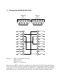
HDVI-10
User’s Manual
Version 0.96b
(2/2004)
Doremi Labs, Inc.
Burbank, California
1 Tables of Contents
1
2
3
Tables of Contents............................................................................................................................2
Description ........................................................................................................................................3
HDVI-10 Operation..........................................................................................................................4
3.1
Auto Mode................................................................................................................................4
3.2
Pass Through Mode..................................................................................................................4
4
HDVI Supported Output Resolutions..............................................................................................5
5
HDVI-10 With 2 Inputs....................................................................................................................5
6
Infrared Remote Functions...............................................................................................................5
7
RS422 Port ........................................................................................................................................6
7.1
Wiring of the RS422-RS232 Cable .........................................................................................7
8
Recommended LCD Monitors.........................................................................................................8
8.1
Note about the Viewsonic VP2290b .......................................................................................8
8.2
Note about the Samsung 240T.................................................................................................8
8.3
Note about the Sony SDM-P232W .........................................................................................8
8.4
Note about the Apple Cinema Displays..................................................................................8
9
HDVI Firmware Update Procedure.................................................................................................9
9.1
Setup..........................................................................................................................................9
9.2
Update using the HDVI_update.bat batch file........................................................................9
10
Specifications..............................................................................................................................10
2 Description
HDVI is a compact digital video interface that converts serial digital video (SDI and HDSDI) to
DVI (digital RGB). It automatically detects the input scan rate and supports a wide variety of video
formats including PAL, NTSC, 720p, 1080p and 1080i.
HDVI can be connected to computer LCD monitors, HDTV Televisions with DVI input, video
projectors and displays (Plasma, DLP, D-ILA etc.). It supports both DVI-HDTV Televisions (no
scaling) and DVI-LCD monitors (automatic scaling).
3 HDVI-10 Operation
On power up, the HDVI-10 will automatically detect the input format of the SDI video and will
send a message to the monitor connected via DVI requesting its EDID parameters. The EDID
parameters of the connected monitor will be used by the HDVI-10 to determine its output
resolution.
The HDVI-10 can operate in two modes. Auto Mode (default) and Pass Through Mode. In all
output modes, the HDVI will always keep the aspect ratio of the input. If you notice a change in the
aspect ratio, it would be caused by the monitor and not by the HDVI-10. Both output modes are
described in detail below.
3.1 Auto Mode
1. EDID reports 1024x768, 1280x720, 1280x768, 1280x800 or 1280x1024: In this case, the
output of the HDVI-10 will be set to match the resolution reported by EDID
2. EDID reports 1920x1200: The output will be set to 1280x800
3. EDID reports 1920x540 (common for HDTV): The output will be set to 1280x720
4. EDID reports none of the above resolutions: The output will be set to 1280x1024
5. EDID message not received (some special cables): The output will be set to 1280x1024
The HDVI-10 output can be forced out of Auto mode to a specific resolution using the “1” button
on a Sony infrared remote control. Pressing the “1” button will jump through the following modes
of operation:
Auto mode (described above), 1024x768, 1280x720, 1280x768, 1280x800, and 1280x1024
A Pass Through Mode is also available (see below).
3.2 Pass Through Mode
This mode can be invoked by pressing the RECALL or JUMP button on a standard Sony infrared
remote control. Pressing the RECALL will toggle to 3 different modes:
1. Pass Through OFF: The output pixel resolution will be displayed at 60 frames per second.
2. Pass Through ON: Available for 1080i, 1080p and 720p inputs. The output resolution will
be the same as the input regardless of the output mode setting. Example: If the input is 24p
(1920x1080-24FPS), the output will be 1920x1080-24FPS. The advantages of this mode:
• No Delay: Since the HDVI-10 does not perform any scaling the conversion delay is
minimal. When the HDVI-10 scales, the delay is 1 frame
• Pixel to Pixel: On monitors that have a resolution above 1920x1080 and support
1920x1080 HD formats, the input can be viewed pixel to pixel without any scaling.
3. Pass Through Frame Rate Only: The output resolution will be displayed at the same frame
rate as the input. This mode is very useful with 24FPS and 25FPS inputs because it
bypasses the frame rate conversion that usually causes motion artifacts.
4 HDVI Supported Output Resolutions
HDVI works with all DVI monitors that support any of the following resolutions:
Automatic Scaling: 1024x768, 1280x720, 1280x768, 1280x800, 1280x1024.
No Scaling: 1080p (1920x1080 @24/25/30), 1080i (1920x540 @48/50/60) and 720p (1280x720
@60).
To save the output resolution to the HDVI-10 flash EPROM, press ENT,1,2,3 on your Sony
infrared monitor. When you reboot the HDVI-10, it will restore the output mode from flash. The
default output mode is Auto Mode.
If the input signal is PAL, you can force the output to 50Hz using the RECALL button on your
Sony infrared remote control.
5 HDVI-10 With 2 Inputs
If you purchased the HDVI-10 with the dual input capability (Model# HDVI-10-2), you can switch
between inputs using the TV/VIDEO button on your standard Sony infrared remote control.
If the input format on both inputs is the same, the switch is immediate. If the input format on both
inputs is different, the switching will take few seconds.
6 Infrared Remote Functions
Starting with version 0.96, the infrared remote functions are disabled at boot time. You must press
ENT,4,5,6 to enable them. This is a list of all the functions that are available on the HDVI-10 using
a standard Sony Infrared Remote Control:
•
•
•
•
•
Input Select “TV/VIDEO”: Switches between SDI input A and input B. This feature is
available only with the dual-input HDVI-10-2.
Set Pass Through Mode “RECALL” or “JUMP”: Toggles the HDVI-10 to Pass Through
ON, Frame Rate Only and OFF. Default is OFF.
Set Color Mode “0”: Toggles the color mode between RGB 0-255, RGB 16-235, Blue only
and Blue only Bright. The default is RGB 0-255.
Set Output Mode “1”: Toggles the output mode between: Auto, 1024x768, 1280x720,
1280x768, 1280x800 and 1280x1024.
Save Current Settings to Flash “ENT,1,2,3”: Saves the current settings to flash.
When you press ENT, the HDVI-10 will not accept any of the remote commands described
above until you press 3 more buttons. If the combination you press is different than 1,2,3,
the save to flash will be aborted.
When you are done using the remote, you can disable its functoionality by pressing “ENT,4,5,6”
7 RS422 Port
The HDVI-10 has an RS422 port that can be used to view the current settings of the unit. To
connect the RS422 port to a PC you need a special RS422-RS232 cable that can be purchased from
Doremi by contacting [email protected] You can also make the cable using the wiring
diagram shown at the end of this document.
•
•
•
Connect COM1 of the PC to the HDVI-10 using the RS422-RS232 cable
Run HyperTerminal on your PC and make a direct connection on COM1
Connection Properties should be set to: 38400 Bauds, 8 Data Bits, Odd Parity, 1 Stop Bit,
and None Flow Control.
When you power up the HDVI-10, plug or unplug the SDI input or DVI output. Messages will be
displayed in the HyperTerminal window indicating the input and output formats as well as the
native monitor resolution reported by the EDID message.
Since the HDVI-10 does not have OSD capabilities, this is the only way to verify the HDVI current
settings.
Auto Mode shows the input format in the message, other modes don’t (see example below)
• “A” or “B” after the input format designates the input channel.
• “p” after the output format designates a progressive output mode.
• “PT” after the output format designates a pass through mode.
Typical output in Auto Mode (1280x1024 LCD)
IN 480iA; OUT 1280x1024p; SC 1280x1024
pix_clk : 10800
activ_h : 1280
blank_h : 408
activ_v : 1024
blank_v : 42
Typical output in Non Auto Mode (1280x1024LCD)
OUT 1280x1024p; SC 1280x1024
pix_clk : 10800
activ_h : 1280
blank_h : 408
activ_v : 1024
blank_v : 42
7.1 Wiring of the RS422-RS232 Cable
(PC/RS232)
DB9-F
Front View
5
4
9
3
8
HDVI-10
DB9-M
Front View
2
7
1
6
6
3
7
4
8
5
9
CD
1
1
Frame GND
RXD
2
2
TXA
TXD
3
3
RXB
DTR
4
4
RX_GND
GND
5
5
SPARE
DSR
6
6
TX_GND
RTS
7
7
TXB
CTS
8
8
RXA
RI
9
9
Frame GND
Shell
Wiring List:
2
1
Shell
HDVI (1) to HDVI Shell to PC Shell
HDVI (2) to PC (2)
HDVI (8) to PC (3)
HDVI (3 + 4 + 6) to PC (5)
Note: For a true RS422 connection, you can use an adapter made by KK Systems (Part Number
K422-99). This adapter connects to the RS232 port on the PC and provides an RS422 connection
on the other side. To connect the K422-99 to the HDVI, use a standard RS422 cable (Male DB9 to
Male DB9 pin to pin). A true RS422 connection allows for a better connection and longer cables.
8 Recommended LCD Monitors
All LCD monitors that support the resolutions listed in this document would work properly with the
HDVI-10. Based on our tests and experience, we recommend the following LCD monitors:
Samsung 172W (17”), NEC LCD1960SX (19”) and Samsung 240T (24”)
If your application uses 16x9 aspect ratio, select the Samsung 172W or 240T
If your application uses 4x3 aspect ratio, select the NEC LCD1960SX or LCD1980SX
For HDTVs and Projectors there is a large selection and Doremi has no specific recommendations.
8.1 Note about the Viewsonic VP2290b
The VP2290b is a 3840x2400 monitor that supports all formats generated by the HDVI-10. In
1080p (24/25/30) pass through mode, this monitor shows the image pixel to pixel. In addition this
monitor is pre-adjusted according to ITU-709 to be used as a high def. reference monitor. The
combination of the HDVI-10 with the VP2290b makes a low cost reference monitor that competes
with CRT reference monitors that are priced above $30,000 US Dollars.
8.2 Note about the Samsung 240T
The 240T is a 1920x1200 LCD monitor that supports all formats generated by the HDVI-10 except
1080p. For 1080i @60 applications we recommend the Samsung 240T over the Sony SDM-P232
because the 240T can display 1080i @60 pixel to pixel.
8.3 Note about the Sony SDM-P232W
The SDM-P232 is a 1920x1200 LCD monitor that supports all formats generated by the HDVI-10
except 1080i and 1080p.
8.4 Note about the Apple Cinema Displays
The Apple Cinema Displays 20” only supports a DVI signal at 1680x1050. The Apple HD Cinema
Displays 23” only supports a DVI signal at 1920x1200. Since the HDVI-10 cannot output these
resolutions, the Apple 20” and 23” monitors will not work with the HDVI-10.
Doremi Labs plans to have a new version of the HDVI converter specifically for the Apple Cinema
Displays available in the 3rd quarter of 2004. Current owners of the HDVI converter can add this
Cinema Display functionality by purchasing the upgrade.
9 HDVI Firmware Update Procedure
To update the firmware on the HDVI you will need the following files:
hdvi_set_flash_mode.exe, HDVI_flash.exe, HDVI_update.bat
and the HDVI_096.bin firmware file.
9.1 Setup
1. Use only a PC running Windows 2000 or Windows XP.
2. All four files listed above should reside in the directory where the command prompt goes to
by default. THIS IS VERY IMPORTANT. Open a Command Prompt Window and see
what directory is listed and copy all four files into that same directory.
3. Connect COM-1 of your PC to the RS422 port of the HDVI using the RS422-RS232 cable
described in this document.
4. Connect your HDVI to a valid SDI source and monitor its output on a DVI monitor.
9.2 Update using the HDVI_update.bat batch file
We created the HDVI_update.bat batch file to simplify the firmware update procedure.
1. Open a command prompt window.
2. Type HDVI_update and hit Enter (DO NOT RUN THE UPDATE BY DOUBLE
CLICKING ON THE HDVI_update.bat FILE)
3. Enter the COM port number and hit Enter. The monitor should lose its display indicating
that the HDVI has entered flash mode. If the monitor does not lose its display, YOU
SHOULD NOT CONTINUE. Contact [email protected].
4. Type "f HDVI_096.bin" (note the space after f) or any other bin file you are upgrading to
then hit Enter.
5. The upgrade process will start by erasing the existing flash and installing the new one.
When done the unit will return a "---- DONE ----" message.
6. Type: "r" then hit Enter to reset the HDVI and quit the application.
It is important to type "r" to reset and quit, otherwise you have to disconnect power from the HDVI
and then connect it back.
10 Specifications
INPUT
SMPTE 259M-C (270Mbps) and SMPTE 292M (1.485, 1.485/1.001 Gbps)
NTSC, PAL,
720p @ 60, 59.94Hz
1080p @ 30, 29.97, 25, 24 & 23.98Hz,
1080i @ 60, 59.94, 50, 48 & 47.95Hz
OUTPUT
DVI (Digital RGB) and DVI-HDTV (Digital RGB with HDTV resolution/frame rate)
Connector: DVI-D, Female, compliant to DVI 1.0
SUPPORTED MONITORS
Depending on your DVI monitor's resolution, the HDVI will either scale the video to fit your
screen, or output the video without scaling.
GENERAL
Size: Prox. 1 1/8th x 3 ¾ x 5 ½ (28mm x 95mm x 14mm)
Power: External Power Adapter with a locking power connector