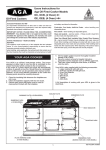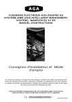
1
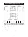
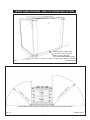
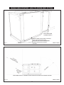
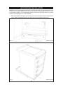
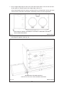
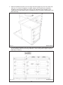
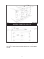
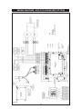
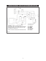
AGA TOTAL CONTROL
Model No’s: TC3 & TC5
(ROOM VENT OPTION)
Installation
Guide
REMEMBER: when replacing a part on this appliance, use only spare parts that
you can be assured conform to the safety and performance specification that we
require. Do not use reconditioned or copy parts that have not been clearly
authorised by AGA.
PLEASE READ THESE INSTRUCTIONS BEFORE COMMENCING SITE SURVEY
OR INSTALLING THIS APPLIANCE.
For use in GB and IE
09/13 EINS 516417
CONTENTS
SECTION
PAGE
HEALTH AND SAFETY
3
INSTALLATION REQUIREMENTS
3
DELIVERY REQUIREMENTS
3
APPLIANCE DIMENSIONS - AGA TC3 (ROOM VENT
OPTION)
4
APPLIANCE DIMENSIONS - AGA TC5 (ROOM VENT
OPTION)
5
CLEARANCES
6
POWER SUPPLY - AGA TC3 (ROOM VENT OPTION)
7
POWER SUPPLY - AGA TC5 (ROOM VENT OPTION)
7
MAINS CABLE ROUTING - AGA TC3 (ROOM VENT OPTION) 8
MAINS CABLE ROUTING - AGA TC5 (ROOM VENT OPTION) 9
HOTCUPBOARD INSTALLATION
10
HANDRAIL CONNECTION - AGA TC3 (ROOM VENT OPTION) 15
WIRING DIAGRAM - AGA TC3 (ROOM VENT OPTION)
16
WIRING DIAGRAM - AGA TC5 (ROOM VENT OPTION)
17
AGA TOTAL CONTROL POST INSTALLATION
CHECKLIST
18
2
HEALTH AND SAFETY
Consumer Protection
As responsible manufacturers we take care to make sure that our products are designed and
constructed to meet the required safety standards when properly installed and used.
PLEASE READ THE ACCOMPANYING WARRANTY.
Any alteration that is not approved by AGA could invalidate the approval of the appliance,
operation of the warranty and could also affect your statutory rights.
In the interests of safety and effective use, please read the following before using your new AGA
appliance.
Important
This appliance may contain some of the materials that are indicated below. It is the
Users/Installers responsibility to ensure that the necessary personal protective clothing is worn
when handling, where applicable, the pertinent parts that contain any of the listed materials that
could be interpreted as being injurious to health and safety, see below for information.
Fire Cement - when handling use disposable gloves.
Glues and Sealants - exercise caution - if these are still in liquid form use face mask and
disposable gloves.
Glass Yarn, Mineral Wool, Insulation Pads - may be harmful if inhaled, may be irritating to
skin, eyes, nose and throat. When handling avoid inhaling or contact with skin or eyes. Use
disposable gloves, face masks and eye protection. After handling wash hands and other
exposed parts. When disposing of the product, reduce dust with water spray, ensure that parts
are securely wrapped.
INSTALLATION REQUIREMENTS
THIS APPLIANCE MUST ONLY BE INSTALLED BY COMPETENT ENGINEERS WHO HAVE
BEEN SPECIFICALLY FACTORY TRAINED ON THE PRODUCT AND WHO HAVE THE
APPROPRIATE EQUIPMENT.
With specific exceptions, the installing of any type of AGA cooker is subject to the respective
directions contained in the current issue of the Building Regulations. In addition, planning
permission may need to be obtained, which should be applied for separately.
The installation of the appliance must be in accordance with the relevant requirements of the IEE
Wiring Regulations and Building Regulations. It should be in accordance also with any
requirements of the local authority.
In your own interest, and that of safety to comply with the law. all appliances should be installed
by an authorised AGA engineer or distributor, in accordance with the relevant regulations.
DELIVERY REQUIREMENTS
The AGA TC3 arrives on 1 pallet.
The AGA TC5 (Hotcupboard Option) arrives on 2 pallets.
There must be access to the kitchen to manipulate a foot print of 1005mm x 740mm. A wooden
template (skate with castor wheels) of dimensions 1005mm x 740mm could be used to check. If
the AGA Total Control fully built appliance is able to fit through the property grounds and doors
into its installation position in the kitchen. It must also be considered that the height of the
appliance is 960mm off pallet and 1100mm on the pallet, so high level obstacles/restrictions must
not be overlooked.
If this skate/template can be manipulated through the property grounds and doors into
position, then the AGA Total Control can be installed as intended with no re-work.
3
APPLIANCE DIMENSIONS - AGA TC3 (ROOM VENT OPTION)
RH SIDE VIEW
FRONT VIEW
LH SIDE VIEW
PLAN VIEW
mm
MINIMUM WALL POSITION
MINIMUM WALL POSITION
Fig. 1
DESN 516297
A
B
C
D
E
F
G
H
J
K
987
945
910
680
1385
760
1145
698
116
10
Cooker Dimensions
When surveying for a cooker installation the actual clearance required for the ‘body’ of the
appliance should be increased by 10mm beyond the figures quote above. This allows safe
margin to take into account the natural dimensional variations found in major castings. In
particular the width across the appliance recess could be critical.
APPLIANCE WEIGHT
Model: AGA Total Control (TC3) - 370 Kg
PACKAGING WEIGHT
515 Kg
DATA PLATE LOCATED BEHIND BOTTOM PLINTH.
4
APPLIANCE DIMENSIONS - AGA TC5 (ROOM VENT OPTION)
Fig. 2
DESN 516561
A
B
mm 1478 945
C
910
D
E
F
680 1385 760
G
H
J
K
L
1145
698
116
10
634
Cooker Dimensions
When surveying for a cooker installation the actual clearance required for the ‘body’ of the
appliance should be increased by 10mm beyond the figures quote above. This allows safe
margin to take into account the natural dimensional variations found in major castings. In
particular the width across the appliance recess could be critical.
APPLIANCE WEIGHT
Model: AGA Total Control (TC3) - 370 Kg
Hotcupboard - 110kg
5
CLEARANCES
The complete cooker is floor-mounted and the space in which the appliance is to be fitted must
have the following minimum dimensions:A minimum clearance of 60mm is required above the raised insulating cover handle.
Side Clearances:- A 3mm gap is required each side between the cooker top plate and adjoining
work surfaces that may be fitted, this is to allow for the safe removal of the top plate should this
be required at a later date.
Where cookers are fitted against side walls a 116mm clearance is required on the right and
left hand side for oven doors access.
If the AGA is to be installed in a brick recess, then the minimum clearance should be
increased by at least 10mm, to allow for the walls not being square.
In addition, a minimum clearance of 1000mm must be available at the front of the cooker
to enable the cooker to be serviced.
Cooker Base or Hearth
It is essential that the base or hearth on which the cooker stands should be level and be capable
of supporting the total weight of the appliance. The base of the built-in AGA plinth must be level
and sit above finished floor height for service access.
The front plinth cover is removable and must not be obstructed by flooring or tiles. If necessary
the cooker must be raised by the thickness of the tiles to ensure the plinth can be removed.
Shims are provided to eliminate rocking.
Tiling
When the cooker is to stand in a recess or against a wall which is to be tiled, in no circumstances
should the tiles overlap the cooker top plate, access to remove the hot plate must be allowed for
servicing at a later date.
A gap of at least 10mm must be observed between the rear of the top plate and the wall behind
the appliance. If the rear wall is of combustible material there must be a gap of 25mm.
Cooker Hoods
It is recommended that this AGA is fitted with a cooker hood. The AGA venting system is located
on top of the AGA between the two hotplates, and is designed for venting the moisture from the
ovens. The cooker hood should be positioned not less than the minimum height as
recommended by the manufacturer, from the top of the AGA.
These are 650mm for AGA Rext 720
650mm for AGA 1000 SE
6
POWER SUPPLY - AGA TC3/TC5 (ROOM VENT OPTION)
WARNING: THIS APPLIANCE MUST BE EARTHED.
THIS APPLIANCE IS DESIGNED FOR THE VOLTAGE STATED ON THE RATING PLATE,
WHICH IS SITUATED BEHIND THE PLINTH COVER.
A 1PH 32 amp 230V or 3PH 400V minimum 16A per phase ~ 50 Hz fused electrical supply is
required adjacent to the appliance. External wiring to the unit must be installed using the mains
cable provided, in accordance with the current wiring regulations and any local regulations which
apply. If cable is shortened, new ferrules must be fitted to the stripped conductors.
The method of connection to the mains electricity supply must facilitate complete electrical
isolation of the appliance, by a multi-pole switch, having a contact separation of at least 3mm on
all poles.
The isolator should not be positioned immediately above the cooker, but must be fitted within 2
metres of the appliance.
The isolator maybe separate from the connection point.
The mains connection point must be accessible within the areas shown in Fig 3A, Page 8 for
cable routing options.
For 2 or 3 phase installations an optional adaptor kit must be obtained (Part No. AE4M280354).
POWER SUPPLY - HOTCUPBOARD (AGA TC5)
THE HOTCUPBOARD ATTACHMENT REQUIRES A INDEPENDENT SINGLE PHASE
SUPPLY.
WARNING: THIS APPLIANCE MUST BE EARTHED.
THIS APPLIANCE IS DESIGNED FOR THE VOLTAGE STATED ON THE RATING PLATE,
WHICH IS SITUATED ON A SLIDE-OUT TRAY IN THE HOT CUPBOARD BASE PLATE
ABOVE THE PLINTH.
A 230v ~ 50 Hz, 3 amp fused electrical supply is required adjacent to the appliance. External
wiring to the unit must be installed using a 3 core silicon - SIHF insulation cable and in
accordance with the current wiring regulations and any local regulations which apply.
The method of connection to the mains electricity supply must facilitate complete electrical
isolation of the appliance, preferably by a fused double pole switch, having a contact separation
of at least 3mm in both poles.
The isolator should not be positioned immediately above the hotcupboard, but must be fitted
within 2 metres of the appliance.
7
MAINS CABLE ROUTING - AGA TC3 (ROOM VENT OPTION)
MAINS CABLE FED FROM
CONTROL TRAY LEFT OR
RIGHT EXIT THROUGH
DUCTING DEPENDENT UPON
POSITION OF SUPPLY SOCKET
Fig. 3
DESN 516420
THE MAINS SUPPLY CONNECT POINT MUST BE WITHIN THE ZONES SHOWN
Fig. 3A
DESN 516419
8
MAINS CABLE ROUTING - AGA TC5 (ROOM VENT OPTION)
HOTCUPBOARD
POWER SUPPLY
MAINS CABLE FED FROM CONTROL
TRAY LEFT OR RIGHT EXIT
THROUGH DUCTING DEPENDENT
UPON POSITION OF SUPPLY
SOCKET
Fig. 4
DESN 516562
THE MAINS SUPPLY CONNECT POINT MUST BE WITHIN THE ZONES SHOWN
Fig. 4A
DESN 516563
9
HOTCUPBOARD INSTALLATION
NOTE: The AGA TC5 hotcupboard should arrive with the top plate in a jacked up position. This
is to allow the complete appliance to be slid onto its plinth when alongside the AGA TC3 without
the top plates clashing. The hotcupboard top plate should then be wound down to its correct
height once the appliance is in its final position.
1. Detach hotcupboard from plinth by removing two screws and tongue bracket from plinth (See
Fig. 5), slide hotcupboard forwards and away from rear fixing bracket (See Fig. 6).
Fig. 5
DESN 516448
Fig. 6
DESN 516449
10
2. Position the plinth alongside the AGA Total Control leaving no gap between the two plinths
(See Fig. 7).
Check with a spirit level that the plinth level is correct, and also check height differential
between the hotcupboard plinth and Total Control plinth is correct (11mm). If necessary, use
shims in each corner to level the plinth.
HOTCUPBOARD
PLINTH BASE
+1
11mm - 0 HEIGHT
DIFFERENTIAL
Fig. 7
DESN 516564
3. Attach hotcupboard plinth to the AGA Total Control plinth using M6 screws and washers
provided (See Fig. 8).
Attach locking screw and jacking screw into plinth. Make sure at this stage that the jacking
screw does not protrude beyond outer face of plinth. Ensure locking screw is located into
AGA TC3 plinth but not fully tightened. A gap of approximately 3mm should be present
between the plinths apart from at the very front where the hotcupboard spacer plate should
be touching the AGA TC3 plinth.
Fig. 8
DESN 516550
11
4. Run a straight edge along the front of the AGA Total Control plinth, to ensure the front face
of both plinths sit squarely against the straight edge. (See Fig. 9)
When satisfied both plinths sit squarely, jacking screws can be tightened until they just make
contact with the AGA Total Control plinth, and locking screws can now be tightened.
Fig. 9
USE STRAIGHT EDGE ACROSS BOTH PLINTHS TO ENSURE PLINTHS
ARE ALIGNED SQUARELY
DESN 516551
5. Front jointing bracket can now be hooked into place over the two pot magnets. This will latch
the two plinths together. (See Fig. 10)
HOOK FRONT JOINTING BRACKET
INTO PLACE TO LOCK TWO PLINTHS TOGETHER
Fig. 10
DESN 516567
12
6. Slide hotcupboard onto plinth until rear tongue bracket engages fully into rear of base slot,
(See Fig. 11). Ensure the appliance is aligned squarely with the plinth then proceed to
engage the front tongue bracket into the slot on the underside of the base plate. Once
satisfied that the front tongue bracket is engaged fully lock it into place by tightening the two
M6 screws fully.
Fig. 11
DESN 516552
7. The hotcupboard top plate is set 5mm higher than the AGA Total Control top plate. This is to
prevent damage to the enamel during installation. Lower the top plate using the adjusters
(See Figs. 12 and 13).
Fig. 12
DESN 516554
13
8. Using the stay rod nut adjusting tool, carefully lower the top plate adjusting nuts until the top
plate sits at the required height, making sure that the top sits level and matches the height of
the AGA TC3. (See Fig. 13).
For servicing requirement, top plate should be removed by raising adjusters approximately
5mm, the top plate can now be removed easily without causing damage to the enamelled
surfaces.
When removing the top plate, the switch wiring harness should be disconnected from the
main wiring harness at the connection point located at the front left hand side of the
appliance, beneath the formex cover sheet.
Fig. 13
DESN 516555
9. Slide the complete handrail assembly over the left hand and centre fixing studs. Once the
assembly has been fitted to the AGA appliance, fit the handrail endcaps (ensuring the
handrail is evenly spaced at each end). The endcaps should be carefully pushed into place
until they sit flush with the outside face of each bracket. (A light smear of lubricant, such as
washing up liquid can be applied to the end cap rubber ‘O’ rings to aid fitment of endcaps into
handrail if required).
The handrail can now be locked into place using the grub screws on the underside of the
handrail brackets.
Finally fit plinth facia onto magnets positioned on plinth, ensuring the facia sits squarely and
centrally.
.
14
Fig. 14
DESN 516569
HANDRAIL CONNECTION - AGA TC3
Fig. 15
DESN 516560
Handrail brackets, endcaps and handrail require assembly.
Locate endcaps onto handrail, place brackets over endcaps and then slide complete assembly
onto locating studs.
Once assembly is correctly located, lock into position with grub screws (located on underside
of handrail).
15
WIRING DIAGRAM - AGA TC3 (ROOM VENT OPTION)
Fig. 16
16
WIRING DIAGRAM - AGA TC5 (HOTCUPBOARD OPTION)
COLOUR KEYS
CAUTION: LABEL ALL WIRES PRIOR TO
DISCONNECTION, WHEN SERVICING CONTROLS
WIRING ERRORS CAN CAUSE IMPROPER AND
DANGEROUS OPERATION.
VERIFY PROPER OPERATION AFTER SERVICING
Fig. 17
17
BR - BROWN
BL - BLUE
GR - GREEN
OR - ORANGE
BK - BLACK
AGA TOTAL CONTROL POST INSTALLATION CHECKLIST
SERIAL No.
Tick Box
l
Check hotplate lids settings.
l
Check oven door seals, adjust door alignment if necessary.
Baking and Simmering Oven rope seals MUST have a gap between the
door hinges. The Roasting Oven is fitted with a continuous seal.
Ensure any plastic film is removed from the inside of the oven doors.
l
Ensure Roasting Oven roof baffle is fitted in the correct position.
l
Gain access to controls tray and check mains voltage, DO NOT remove any
electrical covers to access mains lead. Terminal measurements can be made
through small holes in the cover.
1PH
Record voltage.
3PH
3PH
L1
3PH
L2
L3
l
Switch on cooker, set controls to manual and turn on all cooking zones.
Raise hotplate lids to avoid staining.
l
During warm-up, slow flashing indicator lights will be observed.
l
After 1 hour, check oven and hotplate thermocouple temperatures using
Engineers Handset (approx).
1.
Hotspot (325 - 335°C)
2.
Simmerspot (195 - 205°C)
3.
Roasting Oven (235 - 245°C)
4.
Baking Oven (180 - 185°C)
5.
Simmering Oven (95 - 115°C)
l
During warm-up period, check customer’s handset handshakes and instruct
customer on it’s application and operation.
l
Attach warning label (EGLL516660) to AGA Total Control handrail when
installation is complete. Advise customer to remove and read warning hanger.
l
Guide customer through the Users Instructions of the appliance, offering best
practices on oven maintenance, energy usage, enamel cleaning (boiled
vegetable water staining on enamel etc.)
Engineer’s Signature ........................................................
18
Date ...........................
19
For further advice or information contact
your local AGA Specialist
With AGA Rangemaster’s policy of continuous
product improvement, the Company reserves the
right to change specifications and make
modifications to the appliance described and
illustrated at any time
Manufactured by
AGA Rangemaster
Station Road
Ketley Telford
Shropshire TF1 5AQ
England
www.agaliving.com
www.agacookshop.co.uk
20