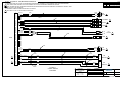
1
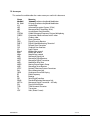
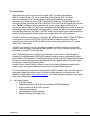
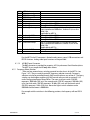
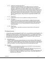
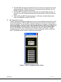
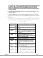
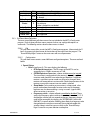
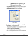
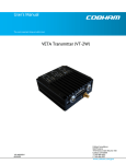
User’s Manual
The most important thing we build is trust.
Messenger Digital Transmitter – ASI Version
MDT-A
100-M0074X1
05/28/09
Cobham Surveillance
GMS Products
1916 Palomar Oaks Way Ste 100
Carlsbad, CA 92008
T: 760-496-0055
F: 760-496-0057
www.cobham.com/gms
Table of Contents
1.0 ACRONYMS................................................................................................................................................................... 4
2.0 INTRODUCTION......................................................................................................................................................... 5
2.1 Key System Features ............................................................................................................................................ 5
3.0 THEORY OF OPERATION......................................................................................................................................... 6
4.0 HARDWARE OVERVIEW.......................................................................................................................................... 6
4.1 MDT-A ........................................................................................................................................................................ 6
4.1.1 MDT-A Connectors ...................................................................................................................................... 7
4.1.1.1 RF Output ..................................................................................................................................................... 7
4.1.1.2 I/O.................................................................................................................................................................... 7
4.1.1.3 ASI BNC Input Connector..................................................................................................................... 8
4.1.2 Frequency Select Switches....................................................................................................................... 8
4.2 Inline Camera Unit (optional)........................................................................................................................... 9
4.2.1 MDT Inline Camera Mount Connectors............................................................................................10
4.2.1.1 RF Output ...................................................................................................................................................10
4.2.1.2 I/O..................................................................................................................................................................10
4.2.1.3 Video Input (Not applicable to MDT-A) .......................................................................................11
4.2.1.4 Power Switch............................................................................................................................................11
4.2.1.5 LCD Display ...............................................................................................................................................11
4.2.1.6 SDI/ASI Input (optional)......................................................................................................................11
5.0 SOFTWARE OVERVIEW ........................................................................................................................................ 11
5.1 System Requirements ........................................................................................................................................11
5.2 Installation..............................................................................................................................................................11
5.3 MDT Configurator Functions..........................................................................................................................12
5.3.1 Function Buttons.........................................................................................................................................13
5.3.2 Field Definitions...........................................................................................................................................14
5.3.3 Pull-Down Menu Definitions ..................................................................................................................15
5.3.3.1 File.................................................................................................................................................................15
5.3.3.2 Configuration ...........................................................................................................................................15
5.3.3.3 Help...............................................................................................................................................................16
6.0 GETTING STARTED ................................................................................................................................................ 18
6.1 Initial Checkout ....................................................................................................................................................18
7.0 SPECIFICATIONS .................................................................................................................................................... 19
7.1 Transport Stream .................................................................................................................................................19
7.2 RS-232 Interfaces/RCU/USB...........................................................................................................................19
7.3 COFDM RF Output...............................................................................................................................................19
7.4 Modulation .............................................................................................................................................................20
7.5 Power ........................................................................................................................................................................20
7.6 Physical Dimensions (without mating connectors)...............................................................................20
7.7 Environmental .......................................................................................................................................................20
7.8 MDT-A Special Features ...................................................................................................................................20
8.0 THE D/C (DOWN CONVERTER)/IF FREQUENCIES EXPLAINED ........................................................... 20
8.1 IF Frequencies.......................................................................................................................................................20
8.2 Local and Remote Power ..................................................................................................................................21
9.0 CABLE LOSSES .......................................................................................................................................................... 23
9.1 Coax Cable..............................................................................................................................................................23
100-M0074X1
2 of 24
www.cobham.com/gms
List of Tables
Table 1 - I/O DB-44 Connector Pin Out......................................................................................................................... 7
Table 2 - I/O DB-15 Connector Pin Out.......................................................................................................................10
Table 3 – MDT-A Field Definitions ................................................................................................................................14
Table 4 - DB-9 Connector Pin Out for the D/C .........................................................................................................22
List of Figures
Figure 2 – MDT-A Connectors........................................................................................................................................... 7
Figure 3 - MDT Inline Camera Unit ................................................................................................................................. 9
Figure 4 – MDT-A Configurator Main Screen ...........................................................................................................12
Figure 5 – MDT-A Configurator Main Screen ...........................................................................................................13
Figure 6 - Others ....................................................................................................................................................................16
Figure 7 - Channel Rate Guide .........................................................................................................................................17
Figure 8 - FW Version..........................................................................................................................................................17
Figure 9 - Basic MDL Setup ...............................................................................................................................................18
Figure 10 - BDC Connectors.............................................................................................................................................22
Appendix
Appendix A – Cable, MDT-A External Breakout.......................................................................................................24
100-M0074X1
3 of 24
www.cobham.com/gms
1.0 Acronyms
This section lists and describes the various acronyms used in this document.
Name
16 QAM
64 QAM
A/V
AES
ABS
ASI
COFDM
CVBS/Y
C
D/C
DDR
DVB-T
FEC
GUI
I/O
Kbaud
Kbps
Mbps
MDL
MDR
MDT
MER
MPEG
MSR
NTSC
PAL
QPSK
RF
RX
SDI
SDML
MDT-A
S/N
THD
TX
VDC
100-M0074X1
Meaning
16-state Quadrature Amplitude Modulation
64-state Quadrature Amplitude Modulation
Audio/Video
Advanced Encryption System (32 bit)
Messenger Basic Scrambling (8 bit)
Asynchronous Serial Interface
Coded Orthogonal Frequency Division Multiplexing
Composite video/Luminance with S-video
Chroma video
Down-Converter
Digital Diversity Receiver
Digital Video Broadcasting-Terrestrial
Forward Error Correction
Graphical User Interface
Input/ Output
Kilobaud per second
Kilobits per second
Megabits per second
Messenger Digital Link
Messenger Digital Receiver
Messenger Digital Transmitter
Modulation Error Rate
Moving Picture Experts Group
Messenger Smart Receiver
National Television System Committee
Phase Alternation Line
Quadrature Phase Shift Keying
Radio Frequency
Receiver
Serial Digital Interface
Standard Definition Messenger Link
Messenger Digital Transmitter – ASI only
Signal-to-Noise Ratio
Total Harmonic Distortion
Transmitter
Volts (Direct Current)
4 of 24
www.cobham.com/gms
2.0 Introduction
GMS’ Messenger Digital Transmitter with ASI option (MDT-A) accepts DVB compliant
MPEG-2 Transport Streams (TS) via an Asynchronous Serial Interface (ASI). The stream
can be scrambled with an AES scrambling algorithm to provide protection in sensitive
applications prior to the final step of DVB-T compliant FEC coding and C-OFDM modulation. The
transmitter provides automatic zero stuffing when the TS rate is less than the channel rate. Data rates
from 100 Kbps to 30 Mbps can be supported. However, the system is optimized for high rate
transmission above 5 Mbps. This transmitter is compatible with GMS’ MSR receiver, which outputs the
recovered ASI stream. When the AES scrambling option is chosen, the MSR must be configured with
the Digital Data Processor Card (DDPC). The DDPC accepts the ASI signal from the MSR and performs
the de-scrambling operation and then outputs the transport stream to an ASI output port.
The MDT-A will transmit any data that is formatted into a DVB compliant MPEG-2 TS per ETSI TBD for
Audio/Video (A/V) data and ETSI EN 301 192 for generic digital data transmission. Other A/V
compression formats such as H.264 and WM-9 can be transmitted provided that the TS structure
follows the TS specification.
The MDT-A can be used as part of a cost effective repeater system by combining it with an MSR,
antennas, down-converters, and optional Power Amplifiers (PAs) The ASI output of the MSR can be
fed directly into the MDT-A’s ASI input port.
GMS’ C-OFDM equipment uses a robust digital modulation system known as Coded Orthogonal
Frequency Division Multiplexed (COFDM) that provides frequency diversity and powerful Forward
Error Correction (FEC) algorithms. The Messenger receiver include an option for Spatial Maximal Ratio
Pre-Detect Diversity Combining to combat short delay spread multipath reflections found in indoor
environments. A Messenger Digital Link (MDL)
provides a robust wireless link that is effective against the multipath interference experienced by
analog systems and provides reliable data transmission in the most difficult of terrains.
This manual provides information on how to operate the MDT-A model as well as pertinent technical
information related to the overall system. Also, refer to model identifier (on-line document, 100MNI0042) at GMS website, www.cobham.com/gms, for available frequency and power configurations
along with available options.
2.1
Key System Features
• ASI Only Interface
• Coded Orthogonal Frequency Division Multiplexed (COFDM) Modulation
• Output Frequency 0.36 to 6 GHz (In-Bands)
• Low Power Consumption
• Local and Remote Control Interfaces
• Rugged and Compact Portable Design
100-M0074X1
5 of 24
www.cobham.com/gms
3.0 Theory of Operation
The MDT-A accepts DVB ASI according to MPEG-2 specifications (Video MPEG-2 and Audio MPEG-1
layer II).
The TS stream is then sent through a DVB-T compliant FEC encoder and C-OFDM modulator. This is
output from the FPGA based modulator core as digital I/Q signals that are converted to Analog I/Q
signals and applied to an I/Q Modulator. The LO that provides the carrier to this I/Q modulator comes
from a low phase-noise programmable synthesizer. The modulated RF output of the I/Q modulator IC
is sent through amplifier chain and ultimately output to the outside world. Programmable attenuators
in the RF processing chain provide signal leveling.
The transmitter is microprocessor controlled. Normally the transmitter is controlled either through an
RS-232 or USB interface via either GMS’ MS Windows control SW or a simple command line interface.
Local Frequency control is also available via rotary switches on the side of the housing.
4.0 Hardware Overview
The MDT-A accepts ASI only data streams. In addition, the MDT-A can be mounted in an inline
professional camera unit (this is an optional enclosure for mounting the MDT-A for professional
camera applications). The hardware configuration is shown below:
4.1
MDT-A
Figure 2 shows a typical MDT-A transmitter with the hardware elements identified.
“RF OUT” SMA Connector)
“ASI Input” (BNC
Connector)
SW100
DB-44 Connector
(I/O and Power)
Frequency
Select Switches.
Figure 2 – MDT-A Connectors
100-M0074X1
6 of 24
www.cobham.com/gms
4.1.1 MDT-A Connectors
4.1.1.1 RF Output
The RF Output connector is an SMA female (Bulkhead).
4.1.1.2
Pin
1
2
3
4
5
6
7
8
9
10
11
12
13
14
15
16
17
18
100-M0074X1
I/O
The ‘I/O’ connector is a male, high-density DB-44. It is used to provide the interface for
external power, audio, analog video, USB and RS-232 signals. The MDT-A has a separate
RS232 channel (labeled “Control” on the external breakout cable) for control and
monitoring the unit. GMS MDT Configurator software program (as explained in section 6)
makes use of the RS232 control lines. The RS-232 channel utilizes a 3-wire configuration.
The pin out for the I/O connector is shown in Table 1. NOTE: An additional RS232
channel (labeled “USER DATA”) is currently provided with the external breakout cable
for future update capabilities, which are currently under development. The
“ USER Data” RS232 channel will be dedicated for low-rate data to be transmitted
along with the audio and video.
The USB connector is an alternate method of interfacing to the PC if DB-9 connectors
are not available.
Table 1 - I/O DB-44 Connector Pin Out
Signal
Notes
Under development
RS232 USER Data Tx
Under development
RS232 USER Data Rx
Under development
RS232 GND
Not connected
SDA
I^2 C bus
SCL
I^2 C bus
CVBS/Y
Dual use input. 1. Composite video in; 2.
Luminance in (when used with S or Component
Video). Must be selected with GMS Control Software
or through the front panel of the in-line camera
mount box . Not applicable for MDT-A
GND
GND for composite video
C/Pr
Dual use input. 1.Chroma video (when used with Svideo); 2. Pr (red component when used with
Component Video). Must be selected with GMS
Control Software or through the front panel of the inline camera mount box. Not applicable for MDT-A
GND
GND for Chroma video/Pr component Not applicable
for MDT-A
Pb
Blue component when used with Component Video.
Not applicable for MDT-A
GND
GND for Pb component Not applicable for MDT-A.
GND
GND
11-15Vdc
Input power to unit
Not connected
+5V
USB power, Reset
USB Data USB Data +
7 of 24
www.cobham.com/gms
19
20-30
31
32
33
34-36
37
38
39
USB Gnd
Not connected
RS232 Control Tx
RS232 Control-Rx
RS232 GND
Not connected
Audio right +
Audio right Audio right line opt.
40
41
42
43
Audio right GND
Audio left +
Audio left Audio left line opt
44
Audio left GND
Not applicable for MDT-A
Not applicable for MDT-A
Pin 39 is connected to pin 38 for audio right channel
input impedance of 600 ohms , balance in (mic or line
level). Not
applicable for MDT-A
Not applicable for MDT-A
Not applicable for MDT-A
Not applicable for MDT-A
Pin 43 is connected to pin 42 for audio left channel
input impedance of 600 ohms; balance in (mic or line
level). Not
Applicable for MDT-A.
Not applicable for MDT-A
For the MDT-A the I/O connector is limited to only power, ground, USB connections and
RS232 functions. Analog video input functions are not provided.
4.1.1.3
4.1.2
ASI BNC Input Connector
The BNC connector is provided for accepting ASI (Asynchronous Serial Interface) data.
The MDT-A can accept the ASI only data streams.
Frequency Select Switches
There are four external rotary switches mounted into the chassis of the MDT-A (see
Figure 1 & 2). They are used to control RF frequency selection manually. Frequency
selection can also be controlled through GMS control software; see section 6. The rotary
switches can be disable or enable using GMS control software; refer to section 6.3.3.2
under Configuration/Special Setup/Others. The most significant switch (SW100)
represents 1000 MHz (0-9) units, the second switch (SW101) represents 100 MHz (0-9)
units, the third switch (SW102) represents 10 MHz (0-9) units and the fourth switch
(SW103) represents 1 MHz (0-9) units. Hence the highest switch selection can be
9999MHz and the lowest is 0000 MHz.
For example with the switches in the following positions, the frequency will read 2014
MHz:
100-M0074X1
8 of 24
www.cobham.com/gms
SW100
9 0 1
8
7
6 5
2
3
4
9 0 1
8
7
6 5
0
2
2
3
4
9 0 1
8
7
6 5
1
2
3
4
9 0 1
8
7
6 5
4
2
3
4
And with the switches in the following positions the frequency will read 924MHz:
SW100
9 0 1
8
7
6 5
2
3
4
0
9 0 1
8
7
6 5
9
2
3
4
9 0 1
8
7
6 5
2
2
3
4
9 0 1
8
7
6 5
4
2
3
4
Note the following: if the switches are selected for a frequency outside the range of the
frequency band of the MDT-A: the transmitter will default to the high side of the frequency
band if the switches are set for a frequency higher than the transmitter frequency band. It
will default to the low side of the frequency band if the switches are set for a frequency
lower than the transmitter frequency band.
4.2
DB-15
Connector
Inline Camera Unit (optional)
Balance
audio,
A1&A2
Pr
Pb
BNC J2=Chroma C
video input when
used with S-video.
When used with
BNC J7 = SDI
or ASI input.
BNC J3, Y/COMP
=Composite video
input. When used with
S or Component video
= Luminance input
Power
“on/off”
switch.
BNC J8 = Pb when
used with
Component video.
Figure 3 - MDT Inline Camera Unit
100-M0074X1
RF out
LCD panel with controls
9 of 24
www.cobham.com/gms
If the MDT-A transmitter is used in the inline camera unit, analog audio and video
functions are not provided. The DB-15 connector and J7 (ASI input) available only.
4.2.1
MDT Inline Camera Mount Connectors
There are four BNC connectors, two audio XLR, one DB-15 connector, one N type connector
and one rocker on/off power switch located on the MDT-A inline camera unit for interfacing the
RF, audio, video, power and RS-232 signals. An optional LCD control front panel is also available.
Inline camera mount is shown in Figure 3.
4.2.1.1
RF Output
The MDT in line camera enclosure uses a female N type connector (flange mount) for its
‘RF Output’ port.
Note: Transmitters should not be powered on without a load. Doing so could
cause the output PA to stop working.
4.2.1.2
I/O
The ‘I/O’ connector is a female, DB-15. It is used to provide the interface for RS-232
signals (control and monitoring). GMS MDT Configurator software program (as explained
in section 6) makes use of the RS232 control lines, pins 2, 3 and 5 of the DB-15
connector. The RS-232 channel utilizes a 3-wire configuration. The pin out for I/O
connector is shown in Table 2. A USB connection is also provided if RS232 port is not
available.
Table 2 - I/O DB-15 Connector Pin Out
100-M0074X1
Pin
1
2
Signal
+12Vdc
RS232-Rx (CTRL)
3
RS232-Tx (CTRL)
4
5
Not connected
RS232-GND
6
7
8
9
10
11
12
13
14
15
I^2C_D
I^2C_C
USB Reset
USB Data USB Data +
USB GND
Not connected
RS232-Tx (DATA)
RS232-Rx (DATA)
RS232-GND
Notes
Relative to MDT-A (i.e., control data is input on this
pin)
Relative to MDT-A (i.e., control data is output on this
pin)
Common ground for both RS232 Data and Control
lines
+5V
Under development/for future updates
Under development
Under development
10 of 24
www.cobham.com/gms
4.2.1.3
Video Input (Not applicable to MDT-A)
The MDT in-line camera enclosure uses female BNC connectors for video input.
Component, Composite or S-Video input is accepted (see section 6 for setting video
input type). J3 BNC connector marked “Y/COMP” is a dual use input connector; a)
Composite Video or b) Luminance when used with Component video. J2 BNC connector
marked “C/Pr” is a dual use input connector; a) Chroma when used with S-Video or b) Pr,
the red component minus the luminance information used with Component Video. J8
BNC connector marked “Pb” is the blue component minus the luminance information
used with Component Video. These video inputs are applicable to the SDMT-C and
MDT-3 units.
4.2.1.4
Power Switch
An LED indicator rocker switch is provided for controlling power to the unit.
4.2.1.5
LCD Display
An optional LCD display with a front control panel is available for the inline camera
mount unit. Many of the control functions which are normally handled through the
software interface and a PC can now be accessed directly with the front control panel
and displayed on the LCD such as changing frequencies, checking video lock status
among many others.
4.2.1.6
SDI/ASI Input
A BNC connector is provided for Asynchronous Digital Interface (ASI) input data
streams.
5.0 Software Overview
Configuration, control and monitoring of the MDT-A unit is accomplished by using GMS’ optional (sold
separately) MS Windows-based MDT Configurator software program. This Graphical User Interface
(GUI) program provides the end user with a straightforward way to interface with the MDT-A. During
normal operation, once a MDL link is established, the MDT Configurator GUI does not need to be
active and can be disconnected from the MDT-A.
5.1
System Requirements
The MDT Configurator program has been developed and tested on Windows 2000, Windows XP
and Windows NT. Although the MDT Configurator program may work properly on other operating
systems, only the Windows 2000, Windows XP and Windows NT environments have been used at
GMS and no support or assistance can be provided concerning other operating systems.
5.2
Installation
The following instructions outline the installation process for the MDT-A Configurator program:
1. Insert provided CD-ROM into computer.
2. Click on ‘setup.exe’ file. This will launch the GMS_MDT Configurator Setup program and
several initial setup files will begin to be copied onto the computer.
3. After the initial setup files are copied over, the GMS_MDT Configurator Setup program will
prompt the user to close any applications that are running. Once all other programs are
exited, click on the ‘OK’ button.
100-M0074X1
11 of 24
www.cobham.com/gms
4. The GMS_MDT Setup program will prompt the user to click on the ‘computer icon’ button
to begin installation. If desired, the user can change the destination directory from the
default. Click on the ‘computer icon’ button.
5. The GMS_MDT Setup program will then prompt the user to ‘Choose Program Group’. If
desired, the user can change the program group from the default. Click on the ‘Continue’
button.
6. After installing the MDT Configurator program, it will display a window indicating that
setup was completed successfully. Click ‘OK’.
5.3
MDT Configurator Functions
The MDT Configurator program provides the user access to many different configuration, control
and monitoring options. When the MDT Configurator program is launched, the screen shown in
Figure 4 is displayed. The user should first select the serial port their computer is connected to via
the Serial Port Selector and Status region. If the selected serial port is valid, the gray-colored status
box will show ‘Ready. To configure a MDT, select the ‘MDT’ box in the Device Selector region.
Once the ‘MDTB/SDMT’ box is selected, the screen shown in Figure 5 is displayed. The MDT
Configurator program contains function buttons and all the configurable settings available on a
MDT. The following sections explain, in detail, the various options.
Figure 4 – MDT-A Configurator Main Screen
100-M0074X1
12 of 24
www.cobham.com/gms
Figure 5 – MDT-A Configurator Main Screen
5.3.1 Function Buttons
• “Enable All” Button: Clicking on this button enables all the check boxes on the screen. This
operation is done to prepare all the fields to be written to (or read from). Alternatively, the end
user can individually select a given field by using the mouse and clicking its corresponding
check box.
•
“Disable All” Button: Clicking on this button disables all the check boxes on the screen. This
operation is done to inhibit all the fields to be written to (or read from). Alternatively, the end
user can individually deselect a given field by using the mouse and clicking its corresponding
check box.
•
“Query” Button: Clicking on this button performs a read operation on all the fields that have
their check box enabled. Once clicked, all the selected fields will be read back reflecting their
current configuration.
•
“Update” Button: Clicking on this button performs a write operation on all the fields that
have their check box enabled. Once clicked, all the selected fields will be written to with the
value denoted in their respective field.
•
“CLR” Button: Clicking on this button clears out all fields on the screen, regardless of whether
the fields’ check boxes are selected or not. This button proves useful when the end user wants
100-M0074X1
13 of 24
www.cobham.com/gms
to verify that a write operation has been correctly performed. An example scenario would be
to 1) enable all fields, 2) change desired field(s), 3) perform a ‘Update’ (write) operation, 4)
perform a ‘CLR’ operation and 5) perform a ‘Query’ operation. As a result of the ‘Query’
operation, the fields on the screen should all update to those values that were written during
the ‘Update’ operation.
•
“Store All Setup Pages” Button: Clicking on this button will store all setup pages, even if
they are not shown.
•
“Reset Tx” Button: Clicking on this button will reset/reboot the MDT-A unit. The system
parameters will be restored to the last saved settings. Reset time is approximately 20 seconds.
5.3.2
Field Definitions
There are several different fields that can be configured by the MDT Configurator. The fields
located in the main screen of Figure 5 and their associated values are defined in Table 3 below.
Also noted in the table is whether the field is read, write-able or both
Table 3 – MDT-A Field Definitions
Field
Unit Name
Unit Number
R/W
R/W
RF Freq
(MHz)
R/W
Modulation
Mode
R/W
C-OFDM
Bandwidth
C-OFDM
Mode
100-M0074X1
R/W
R/W
R/W
Mod Guard
Interval
R/W
Modulation
FEC
R/W
Channel Rate
(Mbps)
R
Description
Allows the user to assign a unique unit name to the
MDT.
Allows the user to assign a unique unit number to
the MDT
RF output frequency. Desired frequency is entered
in MHz (i.e., 1.296 GHz would be entered as 1296).
Default frequency step size is 500 KHz. For S2 band
it’s 250 KHz.
Modulation mode. Desired modulation mode is
selected from the following values: C-OFDM
(default) Off (shuts off modulation) or I/Q CAL ON
(puts unit in calibration mode).
COFDM transmit bandwidth. Desired bandwidth is
selected from the following values: 6, 7 or 8 MHz.
COFDM modulation type. Desired COFDM
modulation type is selected from the following
values: QPSK, 16QAM or 64 QAM (only in ASI
mode)
Modulation guard interval size. Desired modulation
guard interval size is selected from the following
values: 1/32, 1/16, 1/8 or ¼.
Modulation FEC (Forward Error Correction) rate.
Desired modulation FEC rate is selected from the
following values: ½, 2/3, ¾, 5/6, 7/8 .
Channel rate is displayed based on parameters
selected such as COFDM mode, FEC and Guard
Interval. Channel rate must be set to be greater
than the ASI stream rate. Set the channel rate to at
14 of 24
www.cobham.com/gms
Field
Input Mode
5.3.3
R/W
R/W
Video Input
Video Locked
Status
R/W
Audio Enable
Audio Mute
Audio Level
Audio Gain
-
R
Description
least 10 % greater than the ASI stream rate.
The MDT-A defaults to ASI only. No other selection
is allowed.
Not applicable.
Video locked when an ASI stream is present.
Yes,indicates
Video is locked. No, not locked.
Not applicable
Not applicable
Not applicable
Not applicable
Pull-Down Menu Definitions
There are several different pull-down menus that are included in the MDT-A Configurator
program. Each of these pull-down menus contains further user-configurable options or
commands. The following sections describe these menus in detail.
5.3.3.1
File
This pull-down menu offers to exit the MDT-A Configurator program . Alternatively the ‘X’
box in the upper right hand corner of the window can be used to exit the program. The
“Store All Setup Pages” button on the main menu will save all parameters.
5.3.3.2
Configuration
This pull-down menu contains several different configuration options. These are outlined
below:
Special Setup
o Others (see figure 6)- This menu displays the following:
RF Output Attenuation – The RF output of the MDT-A can be
attenuated up to 10 dB in increments of 1 dB.
COFDM Spectrum Inversion - choices include normal or inverted.
The transmitter is configured with the receiver it ships with and the
inversion mode shouldn’t have to be changed. However if a different
receiver is used the inversion mode may have to be changed. Some
receivers will accept either inversion mode. Check the parameters of the
receivers to ensure the correct inversion mode is selected.
Sleep Mode-Can be used to put transmitter in a sleep mode, a low
power mode where the encoder functions and many of the power
regulators are shut down enabling a saving in current (approx. 40%)
when transmitter is not active.
Frequency switch – choices offered are enabled or disabled. These
are the four frequency select switches discussed under section 5.1.2. If
disabled the switches will not respond to changes (frequency changes
could still be accomplish by changing the “RF FREQ MHz” field in the
GMS MDT-A control software. Enabling them allows the frequency to be
changed when the switches are moved. Factory default enables the
switches. Keep in mind that you must click on the “Store All Setup
Pages” button for any new selection to take place.
100-M0074X1
15 of 24
www.cobham.com/gms
Video Profile - Pull down box offers a choice between the SP@ML
profile (default profile) and the MP@ML profile.
GOP Length- Group of pictures size (1-19) can be adjusted by
selecting various values from the pull down boxes.
Ctrl Port Baud Rate- The control port baud rate menu allows different baud rates to
be selected when attached to the PC RS232 port. 115200-baud rate is the default
value. Some computers may need the baud rate adjusted for optimal communications
Factory Setup – reserved for factory use and is password protected.
Figure 6 – Others
5.3.3.3
Help
This pull-down menu contains information about the MDT-A firmware and the MDT-A
Configurator software. This information is outlined below:
Channel Rate Guide: This selection pulls up a table which displays the relationship
between the Modulation mode, Modulation Guard Interval and FEC mode in which the
channel rate (Mbps) is derived. Table values will change depending on which COFDM
Bandwidth is selected. See figure 7. Also keep in mind that all values may not be
available, they are MDT-A configuration type dependant.
FW version: This selection pulls up a window that displays the MDT-A Software
Version date, the FPGA Version and Serial Number. See Figure 8.
About: This selection pulls up a window that displays the Version Number of the GMS
MDT-A Configurator program.
100-M0074X1
16 of 24
www.cobham.com/gms
Figure 7 - Channel Rate Guide
Figure 8 - FW Version
100-M0074X1
17 of 24
www.cobham.com/gms
6.0 Getting Starte
The standard MDT-A kit includes the following items:
MDT-A transmitter unit
MDT-A full breakout cable (GMS p/n 780-C0224)
(Power, A/V, Data, Control interfaces)
NOTE: Based on customer application GMS may deliver additional cables and antennas. Contact GMS
for further information.
The MDT-A is pre-configured by GMS prior to shipment (based on customer requirements), thus is
ready to work “right out of the box”.
6.1
Initial Checkout
Prior to installing a MDT-A unit into the desired target environment, an initial checkout should be
performed to ensure proper operation of the unit. The initial checkout consists of configuring a
basic MDL (Messenger Digital Link).
Figure 9 shows a basic interconnection configuration to establish a wireless MDL (NOTE:
Receivers, down converters (D/C) units and their associated hardware are sold separately). As
mentioned in section 4.0 the MDT-A may be shipped as a stand-alone unit or mounted in an Inline
Camera Mount box. MDT-A stand-alone units require the use of GMS’ breakout cable to provide
power and the necessary interfacing to communicate to the transmitter. The Inline Camera Mount
boxes require a +12 battery and most of the necessary communications can be done through the
LCD front panel. The steps necessary to set up the configuration shown in Figure 9 are shown
below; the differences between the Inline Camera Mount box and stand-alone unit are noted
where applicable.
Figure 9 - Basic MDL Setup
Power Source
MDT
D/C
DVB-T
Power Supply
MDT-A
MDR
ASI
SOURCE
Monitor
100-M0074X1
18 of 24
www.cobham.com/gms
1. Install omni-directional antennas onto the MDT-A RF output port and Down- Converter (D/C)
RF input port. Note: Transmitters should not be powered on without a load. Doing so
could cause the output PA to stop working. A proper heat sink is also required.
2. Attach the breakout cable (DB-44 end) to the MDT-A unit (if unit is mounted in an Inline
Camera Mount Box this step does not apply).
3. Attach a RF cable from the D/C IF output port to RF in port of the receiver.
4. Attach an ASI source to MDT-A BNC ASI input . If unit is mounted in an Inline Camera Mount
Box then attach ASI to appropriate BNC ASI input connector
5. Attach a video cable from one of the BNC video output ports on the receiver to a video
monitor.
6. To prepare to power the MDT-A unit, attach the red and black wires from the breakout cable to
+12V terminal and ground of power supply, respectively (if unit is mounted in an Inline Camera
Mount box then attach +12 Volt battery). NOTE: The power supply (for the transmitter) needs
to be able to provide at least 1.5 Amps of current at a nominal +12VDC input. If using a
commercial DVB-T receiver follow the manufacturer’s instructions for powering the unit.
7. Turn on the ASI source and video monitor equipment.
8. Apply power to the MDT-A and the receiver unit (Inline Camera Mount boxes have power
switches which must be turned on). Also ensure the down converter is powered (+12 Vdc to
pin 1, GND to pin 3 of the DB-9 pin connector located on the bottom side of the D/C). If the
down converter is installed in a camera mount box it will have a power switch on the side of
the unit. Ensure the switch is turned to the “On” position.
9. After approximately 10 seconds, the link should be established and video provided by the
source should be displayed on the monitor.
The initial checkout described above is simply to check the basic video operation of the MDT-A
unit. For further details on monitoring and controlling the MDT-A using GMS’ optional MS
Windows-based MDT-A Configurator software program, see Section 6.0.
7.0 Specifications
The following sections outline the overall specifications for the MDT-A unit.
7.1
Transport Stream
Standard: per ISO/IEC 13818-1
Packet Size: 188 byte
ASI Input :Allows MPEG2 transport stream per EN 300 744
Bit Rate: 100Kps – 30Mbps
7.2
RS-232 Interfaces/RCU/USB
Control Port: 3-wire interface (Tx,Rx,Gnd)
USB 1.0
RCU A remote portable control unit is also available
In addition a “Data” RS232 channel under development will be dedicated for low-rate data
to be transmitted along with the audio and video.
7.3
COFDM RF Output
Output Frequency: 0.36 to 6 GHz (In-Bands).
Frequency step size is 500 KHz for all bands except S2 (1999-2500 MHz) which is 250 KHz.
Bandwidth: Selectable 6, 7 or 8 MHz
100-M0074X1
19 of 24
www.cobham.com/gms
Output Power: Up to100mW (programmable) [200mW on some models]
Connector: SMA-F
Note: Transmitters should not be powered on without a load. Doing so could cause
the output PA to stop working. A proper heat sink is also required.
7.4
Modulation
Modulation Type: COFDM w/ QPSK, 16 QAM , or 64 QAM.
FEC: ½, 2/3, ¾, 7/8
Guard Intervals: 1/32, 1/16, 1/8, ¼
Spurious: 50dBc
Number of C-OFDM Carriers: 2k
C-OFDM MER: > -45dB
Standard: DVB-T compliant
7.5
Power
DC Input Voltage Range: 9 to 15 VDC
Power Consumption: 8.5 Watts to 10.8watts
7.6
Physical Dimensions (without mating connectors)
Size: 3.25 in. (W) x 4.5 in. (D) x 1.76 in. (H)
(8.26 cm x 11.43cm x 4.47cm)
Weight: 13.4 oz (379.9grams)
7.7
Environmental
Operational Temperature: -10 to +70 °C
Humidity: Up to 100% (non-condensing)
7.8
MDT-A Special Features
Security Option
The MDT-A can optionally be provided with an Advanced Encryption System (AES) for protecting the
signal in sensitive applications.
8.0 The D/C (Down Converter)/IF frequencies explained
8.1
IF Frequencies
• GMS’ MDRs (Messenger Digital Receivers) and MSRs (Messenger Smart Receivers) are capable of
receiving direct frequencies in the range of approximately 49 MHz to 861 MHz. If the transmitter
is not in this range then a down-converter is used to convert the frequency to this range. The
frequency from the down-converter is called the IF (intermediate frequency) which is fed to the
receiver.
Down-converters have a LO (local oscillator) which is mixed with the transmitter frequency (MDTA) and converts it to the IF frequency. MDRs need to know the LO (local oscillator) of the downconverter and is factory programmed with this information (MSRs also need the LO information
but is not factory programmed with this information). The receiver then automatically calculates
the IF frequency once the RF (transmitter frequency) is entered. Thus as the desired RF frequency
is dialed in on the MDR (or MSR) the IF is taken care of automatically. For example, if the
100-M0074X1
20 of 24
www.cobham.com/gms
transmitter frequency (MDT-A) is set for 2000MHz, then the MDR can be set for 2000 MHz (it
automatically calculates the IF frequency based on pre-programmed LO information of the downconverter). The IF frequency changes as the RF frequency changes; the LO remains constant.
On non-GMS commercial digital receiver it may be necessary to program the receiver with the IF
frequency directly. The user may need to do the simple math to arrive at the IF frequency so that it
can be entered into the receiver. The down-converter LO must be known. The math involve is
as follows: “ RF (transmitter frequency) – LO (local oscillator) = IF frequency”. For example, it the
transmitter is set for 2000MHz and the LO of the down-converter is 2800MHz then the IF
frequency is -800MHz (2000-2800MHz = -800). The receiver will need to be set to 800MHz to
receive the transmitter frequency of 2000MHz. Each time the transmitter frequency is changed the
IF must be re-calculated and entered into the receiver. It must also be mentioned, as you may have
noticed, a negative LO may indicate the receiver wants the signal to be inverted. See section 5.3.3.2
for inverting the signal.
8.2
Local and Remote Power
Customers may have the option of using remote or local power to power up a down converter
depending on the receiver used. GMS’ MDRs (Messenger Digital Receiver) and MSRs (Messenger Smart
Receiver) can provide DC +12 volts to power the D/C remotely through the RF cables. Refer to GMS’
MDRs or MSRs operating instructions for turning on the DC power for the D/C when using remote
power.
If the D/C is located relatively close to the receiver then using remote power makes sense. However, if
the D/C is located at great distances away from the receiver there may be excessive DC voltage drop in
the coax cable (due to cable resistances). If this is the case then local DC power should be considered
as discussed below. If unsure of the DC voltage drop measure the DC voltage present (using a DMM) at
the end of the coax cable run. The D/C normal operating voltage is approximately +12Vdc but can
operate down to +10Vdc.
•
Local power is provided by applying +12Vdc to pin 1, GND to pin 3 of the DB-9 connector located on
the bottom of the D/C. The +12 Volt power supply must be able to source at least 500mA. The power
switch (located on the side of the D/C) enables the user to control the ‘ON’/’OFF’ positions for local
power. If using local power then ensure the remote power (if the receivers have this capability) is
turned off.
100-M0074X1
21 of 24
www.cobham.com/gms
Power Switch
for local
BNC connector – IF frequency
output
RF N type
connector
DB-9 connector for local
power
Figure 10 - BDC Connectors
Table 4 - DB-9 Connector Pin Out for the D/C
Pin
1
3
2, 4-9
100-M0074X1
Signal
+12Vdc
GND
NC
Notes
Power supply must be able to source at least
500mA. Voltage should not drop below +10Vdc.
Power ground
Not Connected
22 of 24
www.cobham.com/gms
9.0 Cable Losses
9.1
Coax Cable
Cable losses must be taken into consideration if the D/C is located a great distance from the
receiver. As mentioned above long cable runs can contribute to more resistance in the lines and also
can contribute to signal attenuation because of the additional capacitance. Even when using a good
coax cable such as RG59/U the attenuation of the signal can be significant. For example, RG59/U
coax will drop approximately 2dB per 100 feet at 50 MHz and 8 dB per 100 feet at 900 MHz. The
intermediate frequency (IF) in this system can fall between 49 MHz to 850 MHz. An inline amplifier
matching the cable losses should be considered if losses exceed 6dB
100-M0074X1
23 of 24
www.cobham.com/gms
Appendix A – Cable, MDT-A External Breakout
REVISIONS
NOTES:
1. REFERENCE BOM 780-C0224X2 FOR REFERENCE DESIGNATIONS (SHOWN AS [] ON DRAWING) AND PART DESCRIPTIONS .
2 LABEL FINAL CABLE ASSEMBLY WITH PART NUMBER 780-C0224X2 USING BEST COMMERCIAL METHOD.
3 LABEL CONNECTOR WITH REFERENCE DESIGNATOR AND DESCRIPTION AS SHOWN USING BEST COMMERCIAL METHOD. LABEL
TO BE WITHIN 3.0 OF CONNECTOR.
4 REFERENCE MANUFACTURING INSTRUCTION 100-MI0112.
ECO
REV
DESCRIPTION
DATE
E0355X1
X1
INITIAL RELEASE
01/19/04 SLP
E0355X3
X2
Correct polarity marks of USB, pins17&18
APPROVED
11/9/05 TG
5 THIS CABLE IS SET-UP FOR BALANCED AUDIO ONLY.
P100
5
5
1
2
3
4
5
6
7
8
9
10
11
12
13
14
15
16
17
18
19
20
21
22
23
24
25
26
27
28
29
30
31
32
33
34
35
36
37
38
39
40
41
42
43
44
DATA-TX
RED
DATA-RX
WHT
GND
BLK
N/C
N/C
N/C
CVBS/Y
GND
C/Pr
GND
Pb
GND
GND
BLK
RED
11-15VDC
N/C
RED
USB RESET
WHT
USB DATA GRN
USB DATA +
BLK
USB GND
N/C
N/C
N/C
N/C
N/C
N/C
N/C
N/C
N/C
N/C
N/C
RED
CTRL-TX
CTRL-RX
WHT
GND
BLK
N/C
N/C
N/C
AUDIO1 (RIGHT) +
AUDIO1 (RIGHT) -
RED
WHT
BLK
1
2
3
4
5
6
7
8
9
P3
DATA 3
W5
W1
P1 CVBS/Y
3
W2
P2 C/Pr 3
P7 Pb 3
W4
W3
USB
BLK
J1
RED
J2
DC
POWER
3
USB 3
W6
RED
WHT
BLK
W7
W7
RED
GND
AUDIO2 (LEFT) +
AUDIO2 (LEFT) -
RED
BLK
RED
BLK
GND
GND
P4
CTRL 3
2
3
1
P5
AUDIO1 3
2
3
1
P6
AUDIO 2
W7
BLK
RED
BLK
GND
W7
BLK
6
7
8
9
W7
RED
RED
BLK
GND
1
2
3
4
5
GND
FIGURE 1
CABLE WIRING
DIAGRAM
TOLERANCES
UNLESS OTHERWISE SPECIFIED
DIMENSIONS ARE IN INCHES
DO NOT SCALE DRAWING
LINEAR
X.X = ± 0.5
X.XX = ± 0.125
X.XXX = ± 0.020
ENG/TECH
DRAWN
ENG
PROD
QC
3
T. Giotta
gnd/shield
DWG TITLE
SLP
CABLE, MDT2-B EXTERNAL BREAKOUT FOR
BROADCAST VERSION
GMS Products
SIZE
DATE
DWG NO
REV
B
11/9/05
100-C0224X2
X2
SCALE:
NONE
24 of 24
SHEET
1 OF 5