1
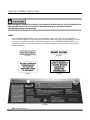
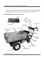
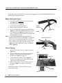
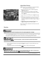
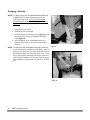
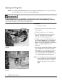
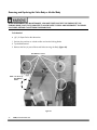
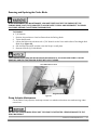
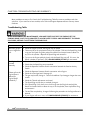
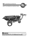
DR® POWERWAGON-PRO
SAFETY & OPERATING INSTRUCTIONS
READ AND UNDERSTAND THIS MANUAL AND ALL INSTRUCTIONS
BEFORE OPERATING THE DR POWERWAGON-PRO.
Table of Contents
CHAPTER 1: INTRODUCING THE DR POWERWAGON-PRO ............................................1
CHAPTER 2: GENERAL SAFETY RULES ................................................................................2
CHAPTER 3: SETTING UP YOUR DR POWERWAGON-PRO...............................................8
CHAPTER 4: OPERATING YOUR DR POWERWAGON-PRO.............................................12
CHAPTER 5: MAINTAINING THE DR POWERWAGON-PRO ...........................................18
CHAPTER 6: TROUBLESHOOTING AND WARRANTY .....................................................32
CHAPTER 7: PARTS LISTS, SCHEMATIC DIAGRAMS AND WARRANTY .........................35
II
DR® POWERWAGON-PRO
CHAPTER 1: INTRODUCING THE DR POWERWAGON-PRO
This manual will help you set up and safely operate your new DR POWERWAGON-PRO. Careful
adherence to the safety and operating instructions in this manual will ensure many years of productive
use. Please let us know of any questions you may have. We want to answer them as quickly as possible.
When you do call, please have your order number, or serial number handy. For technical assistance,
please call Toll-Free 1-800-DR-OWNER (376-9637) and one of our Technical Support Representatives will
be happy to help you.
Conventions used in this manual
THIS INDICATES A HAZARDOUS SITUATION, WHICH, IF NOT AVOIDED, COULD RESULT IN DEATH OR
SERIOUS INJURY.
THIS INDICATES A HAZARDOUS SITUATION, WHICH, IF NOT AVOIDED, COULD RESULT IN MINOR OR
MODERATE INJURY.
THIS INFORMATION IS IMPORTANT IN THE PROPER USE OF YOUR MACHINE. FAILURE TO FOLLOW
THIS INSTRUCTION COULD RESULT IN DAMAGE TO YOUR MACHINE OR PROPERTY.
Tip: This is a helpful hint to guide you in getting the most out of your DR POWERWAGON-PRO.
Tools Needed: This indicates you will need a special tool to perform a maintenance function on your
machine.
NOTE: This information may be helpful to you.
If you are ever unsure about an action you are about to take, don’t do it, contact Country Home
Products’ Toll-Free support at 1-800-DR-OWNER (376-9637) for help or information.
Contact us at www.DRpower.com
1
CHAPTER 2: GENERAL SAFETY RULES
READ THIS SAFETY & OPERATING INSTRUCTIONS MANUAL BEFORE YOU USE THE DR POWERWAGONPRO. BECOME FAMILIAR WITH THE SERVICE RECOMMENDATIONS TO ENSURE THE BEST
PERFORMANCE FROM YOUR MACHINE.
Labels
Your DR POWERWAGON-PRO carries prominent labels as reminders for its proper and safe use.
Shown below are copies of all the safety and information labels that appear on the equipment. Take a
moment to study them and make a note of their location on your DR POWERWAGON-PRO as you
assemble and before you operate the machine. Replace damaged or missing safety and information
labels immediately.
#153421
#137581
#153431
#153441
#161531
2
DR® POWERWAGON-PRO
Protecting Yourself
THIS IS A HIGH-POWERED MACHINE, WITH MOVING PARTS OPERATING WITH HIGH ENERGY AT
HIGH SPEEDS. USE PROPER CLOTHING AND SAFETY GEAR WHEN OPERATING THIS MACHINE TO
PREVENT OR MINIMIZE THE RISK OF SEVERE INJURY. YOU MUST OPERATE THE MACHINE SAFELY.
UNSAFE OPERATION CAN CREATE A NUMBER OF HAZARDS FOR YOU. ALWAYS TAKE THE FOLLOWING
PRECAUTIONS WHEN OPERATING THIS MACHINE:
• WEAR SHOES WITH NON-SLIP TREADS WHEN USING YOUR DR POWERWAGON-PRO. IF YOU HAVE
SAFETY SHOES, WE RECOMMEND WEARING THEM. DO NOT USE THE MACHINE WHILE BAREFOOT
OR WEARING OPEN SANDALS.
• AVOID WEARING LOOSE CLOTHING OR JEWELRY, WHICH CAN CATCH ON THE MACHINE’S
MOVING PARTS.
• USE EAR PROTECTORS OR EAR PLUGS RATED FOR AT LEAST 20 DBA TO PROTECT YOUR HEARING.
• NEVER ALLOW PEOPLE WHO ARE UNFAMILIAR WITH THESE INSTRUCTIONS TO USE THE DR
POWERWAGON-PRO. ALLOW ONLY RESPONSIBLE INDIVIDUALS WHO ARE FAMILIAR WITH THESE
RULES OF SAFE OPERATION TO USE YOUR MACHINE.
• NEVER PLACE YOUR HANDS, FEET, OR ANY PART OF YOUR BODY NEAR OR UNDER ANY MOVING
PART WHILE THE MACHINE IS RUNNING.
• TO BE SAFE, DO NOT OPERATE THE MACHINE NEAR SMALL CHILDREN OR PETS, AND NEVER
ALLOW CHILDREN TO OPERATE THE DR POWERWAGON-PRO.
• THE MUFFLER AND ENGINE BECOME VERY HOT AND CAN CAUSE A SEVERE BURN; DO NOT
TOUCH.
• NEVER, UNDER ANY CONDITIONS, REMOVE, BEND, CUT, FIT, WELD, OR OTHERWISE ALTER
STANDARD PARTS ON THE DR POWERWAGON-PRO. THIS INCLUDES ALL SHIELDS AND GUARDS.
MODIFICATIONS TO YOUR MACHINE COULD CAUSE PERSONAL INJURIES AND WILL VOID YOUR
WARRANTY.
Contact us at www.DRpower.com
3
Slope Operation
SLOPES ARE A MAJOR FACTOR RELATED TO SLIP AND FALL ACCIDENTS, WHICH CAN RESULT IN
SEVERE INJURY. ALL SLOPES REQUIRE CAUTION. IF YOU FEEL UNEASY ON A SLOPE, DO NOT USE
THE DR POWERWAGON-PRO ON IT. ALWAYS TAKE THE FOLLOWING PRECAUTIONS WHEN USING
THIS MACHINE ON SLOPES:
ALWAYS:
• TRAVERSE UP AND DOWN THE FACE OF SLOPES; NEVER ACROSS. EXERCISE EXTREME CAUTION
WHEN CHANGING DIRECTION ON SLOPES.
• WATCH FOR HOLES, RUTS, OR BUMPS IN THE LANDSCAPE.
• USE 1ST GEAR ON SLOPES WITH A MAXIMUM LOAD OF 800 LBS.
NEVER:
• OPERATE NEAR DROP-OFFS, DITCHES, OR EMBANKMENTS; YOU COULD LOSE YOUR FOOTING OR
BALANCE.
• OPERATE ON SLOPES GREATER THAN 20 DEGREES, OR ANY EXCESSIVELY STEEP SLOPES.
• OPERATE ON WET, OR SLIPPERY SLOPES; REDUCED TRACTION COULD RESULT IN SLIPPING.
• PARK THE DR POWERWAGON-PRO ON A STEEP GRADE OR SLOPE.
Safety for Children
TRAGIC ACCIDENTS CAN OCCUR IF THE OPERATOR IS NOT ALERT TO THE PRESENCE OF CHILDREN.
CHILDREN ARE OFTEN ATTRACTED TO THE MACHINE AND THE HAULING ACTIVITY. NEVER ASSUME
THAT CHILDREN WILL REMAIN WHERE YOU LAST SAW THEM.
• KEEP CHILDREN OUT OF THE WORK AREA AND UNDER THE WATCHFUL CARE OF A RESPONSIBLE
ADULT.
• BE ALERT AND ALWAYS TURN OFF THE DR POWERWAGON-PRO ENGINE IF CHILDREN ENTER THE
WORK AREA.
• BEFORE, AND WHILE MOVING BACKWARDS, LOOK BEHIND, AND DOWN FOR SMALL CHILDREN.
• NEVER ALLOW CHILDREN TO OPERATE THE DR POWERWAGON-PRO.
• USE EXTRA CARE WHEN APPROACHING BLIND CORNERS, SHRUBS, TREES, OR OTHER OBJECTS
THAT MAY OBSCURE YOUR VISION.
4
DR® POWERWAGON-PRO
Safety with Gasoline-Powered Machines
GASOLINE IS A HIGHLY FLAMMABLE LIQUID. GASOLINE ALSO GIVES OFF FLAMMABLE VAPOR THAT
CAN BE EASILY IGNITED AND CAUSE A FIRE OR EXPLOSION. NEVER OVERLOOK THE HAZARDS OF
GASOLINE. ALWAYS FOLLOW THESE PRECAUTIONS:
• NEVER RUN THE ENGINE IN AN ENCLOSED AREA OR WITHOUT PROPER VENTILATION AS THE
•
•
•
•
•
•
•
•
•
•
•
•
EXHAUST FROM THE ENGINE CONTAINS CARBON MONOXIDE, WHICH IS AN ODORLESS,
TASTELESS, AND DEADLY POISONOUS GAS.
STORE ALL FUEL AND OIL IN CONTAINERS SPECIFICALLY DESIGNED AND APPROVED FOR THIS
PURPOSE AND KEEP AWAY FROM HEAT AND OPEN FLAME, AND OUT OF THE REACH OF CHILDREN.
FILL THE GASOLINE TANK OUTDOORS WITH THE ENGINE OFF AND ALLOW THE ENGINE TO COOL
COMPLETELY. DO NOT HANDLE GASOLINE IF YOU OR ANYONE NEARBY IS SMOKING, OR IF YOU
ARE NEAR ANYTHING THAT COULD CAUSE IT TO IGNITE OR EXPLODE. REPLACE THE FUEL TANK
AND FUEL CONTAINER CAPS SECURELY.
IF YOU SPILL GASOLINE, DO NOT ATTEMPT TO START THE ENGINE. MOVE THE MACHINE AWAY
FROM THE AREA OF THE SPILL AND AVOID CREATING ANY SOURCE OF IGNITION UNTIL THE GAS
VAPORS HAVE DISSIPATED. WIPE UP ANY SPILLED FUEL TO PREVENT A FIRE HAZARD AND
PROPERLY DISPOSE OF THE WASTE.
ALLOW THE ENGINE TO COOL COMPLETELY BEFORE STORING THE DR POWERWAGON-PRO IN ANY
ENCLOSURE. NEVER STORE THE MACHINE WITH GAS IN THE TANK OR A FUEL CONTAINER, NEAR
AN OPEN FLAME OR SPARK SUCH AS A WATER HEATER.
NEVER MAKE ADJUSTMENTS OR REPAIRS WITH THE ENGINE RUNNING. DISCONNECT THE SPARK
PLUG WIRE AND KEEP THE WIRE AWAY FROM THE SPARK PLUG TO PREVENT ACCIDENTAL
STARTING.
NEVER CHECK FOR AN IGNITION SPARK WITH THE SPARK PLUG OR SPARK PLUG WIRE REMOVED.
USE AN APPROVED SPARK TESTER.
NEVER TAMPER WITH SAFETY DEVICES. CHECK THEIR PROPER OPERATION REGULARLY.
DO NOT CHANGE THE ENGINE GOVERNOR SETTINGS OR MODIFY THE ENGINE SPEED.
MODIFICATIONS WILL VOID YOUR WARRANTY.
TO REDUCE FIRE HAZARD, KEEP THE ENGINE COOLING FAN AND MUFFLER AREA FREE OF DEBRIS
BUILD-UP SUCH AS LEAVES, GRASS, OIL, GREASE OR ANY OTHER COMBUSTIBLE MATERIAL.
NEVER OPERATE THE ENGINE WITHOUT THE MUFFLER. INSPECT THE MUFFLER PERIODICALLY
AND REPLACE IF NECESSARY. IF EQUIPPED WITH A MUFFLER DEFLECTOR, INSPECT THE
DEFLECTOR PERIODICALLY AND REPLACE IF NECESSARY.
NEVER OPERATE THE ENGINE WITH THE AIR CLEANER OR COVER OVER THE CARBURETOR AIR
INTAKE REMOVED, EXCEPT FOR ADJUSTMENT. REMOVAL OF SUCH PARTS COULD CREATE A FIRE
HAZARD. DO NOT USE FLAMMABLE SOLUTIONS TO CLEAN AIR FILTER.
ALWAYS CHECK FUEL LINES AND FITTINGS FREQUENTLY FOR CRACKS OR LEAKS, REPLACE IF
NECESSARY.
Contact us at www.DRpower.com
5
General Safety
• THE DR POWERWAGON-PRO MUST BE OPERATED SAFELY TO PREVENT OR MINIMIZE THE RISK OF
MINOR OR MODERATE INJURY. UNSAFE OPERATION CAN CREATE A NUMBER OF HAZARDS FOR
YOU. ALWAYS TAKE THE FOLLOWING PRECAUTIONS WHEN OPERATING THIS MACHINE:
KEEP IN MIND THAT THE OPERATOR OR USER IS RESPONSIBLE FOR ACCIDENTS OR HAZARDS
OCCURRING TO OTHER PEOPLE, THEIR PROPERTY, AND THEMSELVES.
YOUR DR POWERWAGON-PRO IS NOT A PLAYTHING. EXERCISE EXTREME CAUTION AT ALL TIMES.
THE DESIGN OF THIS MACHINE IS TO HAUL MATERIAL. DO NOT USE IT FOR ANY OTHER PURPOSE.
GIVE COMPLETE AND UNDIVIDED ATTENTION TO THE JOB AT HAND. BEFORE YOU USE YOUR NEW
MACHINE, BE SURE YOU KNOW HOW TO ENGAGE THE PARKING BRAKE AND STOP THE DR
POWERWAGON-PRO AT A MOMENT'S NOTICE.
ALWAYS OPERATE THE DR POWERWAGON-PRO FROM BEHIND THE HANDLEBARS, NEVER FROM THE
SIDE.
NEVER USE THE DR POWERWAGON-PRO TO DRAG OR TOW ITEMS.
DO NOT OVERLOAD THE DR POWERWAGON-PRO. BE CAREFUL OF TOP-HEAVY LOADS. THE HIGHER
THE LOAD, THE MORE CHANCE OF TIPPING OVER THE MACHINE. ALSO, LOADS MAY SHIFT DURING
OPERATION; SO TO BE SAFE, SECURE YOUR LOADS AND EVEN THEM OUT WHEN POSSIBLE. THE
MAXIMUM LOAD IS 800 LBS.
USE 1ST GEAR WITH LOADS OVER 300 LBS. AND ON SLOPES. EXCESSIVE SPEED CAN BE DANGEROUS.
OPERATE THE MACHINE IN THE LOWEST GEAR THAT IS SATISFACTORY TO DO THE JOB.
USE CAUTION WHEN MOVING DOWNHILL AND BRAKING. APPLY THE PARKING BRAKE SLOWLY TO
AVOID TIPPING FORWARD.
WHEN SHIFTING TO REVERSE, BE CAREFUL TO AVOID TIPPING AS THE SWIVEL WHEEL CHANGES
DIRECTION.
WATCH FOR TRAFFIC WHEN OPERATING NEAR ROADWAYS.
NEVER ALLOW PEOPLE OR PETS TO RIDE IN THE DR POWERWAGON-PRO.
IF THE MACHINE SHOULD START MAKING AN UNUSUAL NOISE OR VIBRATION, STOP THE ENGINE
AND WAIT FIVE (5) MINUTES TO COOL. VIBRATION IS GENERALLY A WARNING OF TROUBLE.
DISCONNECT THE SPARK PLUG WIRE AND INSPECT FOR DAMAGED PARTS. CLEAN AND REPAIR
AND/OR REPLACE DAMAGED PARTS.
BUILT-IN SAFETY FEATURES, SUCH AS THE OPERATOR PRESENCE SYSTEM, ARE EFFECTIVE ONLY
WHEN MAINTAINED AND KEPT IN PLACE.
ALWAYS KEEP THE EQUIPMENT IN A GOOD SAFE OPERATING CONDITION. ALWAYS MAKE CERTAIN
NUTS AND BOLTS ARE TIGHT AND ALWAYS USE THE SUPPLIED SELF-LOCKING HARDWARE; DO NOT
SUBSTITUTE. USE ONLY APPROVED DR PARTS.
USE THE DR POWERWAGON-PRO ONLY IN DAYLIGHT.
WHILE USING THE MACHINE, DO NOT HURRY OR TAKE THINGS FOR GRANTED. WHEN IN DOUBT
ABOUT THE EQUIPMENT OR YOUR SURROUNDINGS, STOP THE MACHINE AND TAKE THE TIME TO
LOOK THINGS OVER. MAKE SURE THAT YOU HAVE 100% CONTROL OF THE MACHINE AT ALL TIMES.
NEVER LEAVE THE DR POWERWAGON-PRO UNATTENDED WITH THE ENGINE RUNNING.
DO NOT OPERATE THE MACHINE WHEN UNDER THE INFLUENCE OF ALCOHOL, DRUGS, OR
MEDICATION.
•
•
•
•
•
•
•
•
•
•
•
•
•
•
•
•
•
•
6
DR® POWERWAGON-PRO
• SEE MANUFACTURER’S INSTRUCTIONS FOR PROPER OPERATION AND INSTALLATION OF
ACCESSORIES. ONLY USE ACCESSORIES APPROVED BY COUNTRY HOME PRODUCTS, INC.
• NO LIST OF WARNINGS AND CAUTIONS CAN BE ALL-INCLUSIVE. IF SITUATIONS OCCUR THAT ARE
NOT COVERED BY THIS MANUAL, THE OPERATOR MUST APPLY COMMON SENSE AND OPERATE
THIS MACHINE IN A SAFE MANNER. CALL TOLL-FREE 1-800-DR-OWNER (376-9637) FOR ASSISTANCE.
A Note To All Users
Under California law, and the laws of some other states, you are not permitted to operate an internal
combustion engine using hydrocarbon fuels without an engine spark arrester. This also applies to
operation on US Forest Lands. All DR POWERWAGON-PROS shipped to California and Washington
State are provided with spark arresters. Failure of the owner/operator to maintain this equipment in
compliance with state regulations is a misdemeanor under California law and may be in violation of other
state and/or federal regulations. Contact your local fire marshal or forest service for specific information
in your area.
Additional Information and Potential Changes
Country Home Products, Inc. reserves the right to discontinue, change, and improve its products at any
time without notice or obligation to the purchaser. The descriptions and specifications contained in this
manual were in effect at printing. Equipment described within this manual may be optional. Some
illustrations may not be applicable to your machine.
Contact us at www.DRpower.com
7
CHAPTER 3: SETTING UP YOUR DR POWERWAGON-PRO
This chapter outlines a few simple steps you will need to follow to set up your new machine before you use
it. It may be helpful to familiarize yourself with the controls and features on your DR POWERWAGON-PRO
by reviewing the picture on this page before beginning the steps outlined in this chapter.
DR POWERWAGON-PRO Controls and Features
Shift Lever
Operator Presence Lever
Key Switch
Brake Control
(Right Handlebar)
Stake Body
Removable Tool Tray
Removable Front Panel
(for dumping)
Throttle Control
Manual Recoil
(not shown)
Fuel and Oil
Reservoirs
(not shown)
Dump Lever
(not shown)
Battery
(Electric-starting model only)
Removable Weight Blocks
All-Terrain Tires
Figure 1
8
DR® POWERWAGON-PRO
Unpacking the DR POWERWAGON-PRO
Tools & Supplies Needed:
•
•
•
•
•
•
Screwdriver
Hammer
Knife
Gloves
Eye protection
Metal shears
ALWAYS WEAR EYE PROTECTION WHEN CUTTING THE BANDING. THE BANDING MAY HAVE A LOT OF
TENSION ON IT AND MAY SNAP, STRIKING YOU WHEN CUT. ALWAYS STAND TO ONE SIDE WHEN
CUTTING THE BAND.
1.
Stand to one side and cut the banding.
2.
Remove the top of the carton. Cut the cardboard top to bottom on one of the narrow sides of the
box and peel it off the pallet. Be careful of the staples.
3.
Pry off the fasteners and cut any ties holding the machine to the pallet.
4.
Roll the DR POWERWAGON-PRO off the pallet. Do not discard your pallet and packaging material
until you are fully satisfied with your machine.
BE SURE TO FILL YOUR ENGINE WITH OIL AND GAS BEFORE USE. SEE PAGE 10.
Check the Tire Pressure
DO NOT OVER INFLATE THE TIRES. INFLATE TO THE MANUFACTURERS RECOMMENDED PRESSURE
FOUND ON THE TIRES.
Tools Needed:
• Tire Pressure Gauge
• Air Compressor
1.
Remove the Valve Stem Protective Cap and check the tire pressure with a tire pressure gauge.
2.
If the pressure is too low, add air through the Valve Stem with an air hose.
3.
Replace the Valve Stem Protective Cap when finished.
NOTE: The heavier the load, the higher the tire pressure should be. Do not go above the maximum recommended
load or pressure.
Contact us at www.DRpower.com
9
Adding Oil and Gasoline
YOU MUST ADD OIL BEFORE STARTING THE ENGINE. THIS MACHINE SHIPPED WITHOUT OIL.
TRACES OF OIL MAY BE IN THE RESERVOIR FROM FACTORY TESTING, BUT YOU MUST ADD OIL
BEFORE STARTING THE ENGINE. FILL THE RESERVOIR SLOWLY, CHECKING THE DIPSTICK
FREQUENTLY TO AVOID OVERFILLING.
Engine Oil Capacity
Briggs & Stratton 6.75 Torque, Quantum
20 oz. (0.60 L)
Tool Tray
TO GET AN ACCURATE READING WHEN CHECKING THE OIL LEVEL:
• THE MACHINE SHOULD BE ON A LEVEL SURFACE.
• THE DIPSTICK SHOULD BE SCREWED DOWN ON BRIGGS & STRATTON ENGINES.
Tip: To avoid confusion, we recommend leaving
the Caps on the Fuel and Oil Fills until you
are ready to pour either gasoline or oil into
the correct Fill.
Use only SAE 30 High Detergent oil. Other types
of oil could cause problems operating your
machine. Please refer to your Engine Owner’s
Manual for detailed oil information.
NOTE: You must remove the tool tray to access
the Oil and Fuel Reservoirs.
1.
Place the machine on a level surface and initially add
16 oz. (1/2 quart) of SAE 30 High Detergent oil
recommended by the Engine Manufacturer and wait
one minute for the oil to settle (Figure 2).
2.
Check the Dipstick and continue adding a few ounces
of oil at a time, rechecking the Dipstick until the oil
reaches the fill mark. Be careful not to overfill.
3.
Fill the Fuel Tank to not more than 1/4" from the
bottom of the Fill Neck with fresh, unleaded gas. See
the Engine Manufacturer’s Owner’s Manual for more
information.
Oil Fill
Figure 2
10
DR® POWERWAGON-PRO
Fuel Fill
Connect the Battery Wires
Connect the red wires to each other (Figure 3). The black wires were connected at the factory.
Red Wires Connected
Figure 3
Contact us at www.DRpower.com
11
CHAPTER 4: OPERATING YOUR DR POWERWAGON-PRO
This chapter covers the procedures for starting and stopping your new DR POWERWAGON-PRO and
discusses basic operation features.
Before Starting the Engine
1.
Check the oil level every time you use the machine
(See Figure 2 on page 10).
2.
Check the gas level (Figure 2).
3.
Check the tires for proper inflation.
4.
Make sure the Dump Latch is secured.
5.
Set the Parking Brake by squeezing the Brake Lever
(Figure 4) on the right Handlebar and lift up on the
Parking Brake Lock (Figure 4), locking the Lever in
place. To release the Parking Brake, just squeeze the
Parking Brake Lever again.
Parking
Brake Lever
Parking Brake
Lock
Figure 4
NOTE: The DR POWERWAGON-PRO is equipped with an
Operator Presence Control for added safety. The Operator
Presence Lever must be depressed whenever the Shift
Lever is in gear, or the Engine will stop. You may run the
Engine without depressing the Operator Presence Lever
(Figure 5) only if the Shift Lever is in the "N" (Neutral)
position (Figure 6).
Operator Presence Lever
Electric Starting
1.
Move the Shift Lever to the "N" (Neutral) position
(Figure 6).
2.
Set the Choke Lever on the Engine to the CHOKE
position (to the RUN position if the Engine is
already warm, Figure 7 on page 13).
3.
Turn the Key to the START position (Figure 6).
As soon as the Engine starts, release the Key, and
it will return to the RUN position.
4.
After the Engine starts, move the Choke Lever on
the Engine (Figure 7 on page 13) to the RUN
position.
Throttle
Figure 5
Shift Lever
See the Engine Owner's Manual for information on
cold weather starting.
Key
Figure 6
12
DR® POWERWAGON-PRO
Manual Recoil Starting
NOTE: Manual recoil starting can be used for both ElectricStarting and Manual-Starting models.
Choke
Lever
1. Move the Shift Lever to the "N" (Neutral) position
(Figure 6 on page 12).
2. Set the Choke Lever on the Engine to the CHOKE
position (to the RUN position if the Engine is already
warm, Figure 7).
3. Turn the Key to the START position (Figure 6 on page
12).
4. Pull the Recoil Handle slowly, until you feel resistance;
then pull the Handle with a rapid, full arm stroke to
overcome compression and start the Engine. Repeat if
necessary.
5. After the Engine starts, squeeze the Throttle Lever
(Figure 5 on page 12) to the desired speed.
Figure 7
See the Engine Owner's Manual for information on cold
weather starting.
Operating
ALWAYS RELEASE THE THROTTLE WHEN SHIFTING TO AVOID DAMAGING THE GEARS.
The DR POWERWAGON-PRO has a four-speed forward transmission and single-speed reverse. Use the
lower gears for slower speeds, heavy loads, or more power, and the higher gears for transport.
WHEN ENGAGING REVERSE, USE EXTRA CAUTION. CHECK YOUR PATH AND FOOTING BEFORE
ENGAGING THE CLUTCH.
1.
With the Operator Presence Lever depressed (Figure 5 on page 12), move the Shift Lever to the
desired gear.
2.
Squeeze the Throttle on the left Handlebar slowly until you reach your desired speed.
SQUEEZING THE THROTTLE FAST WILL MAKE THE DR POWERWAGON-PRO "JUMP" INTO MOTION.
SQUEEZE THE THROTTLE SLOWLY AND EASE THE MACHINE INTO GEAR.
Contact us at www.DRpower.com
13
Stopping
BE CAREFUL WHEN TRANSPORTING HEAVY LOADS WITH YOUR DR POWERWAGON-PRO. IF THE
PARKING BRAKE IS APPLIED SUDDENLY, THE LOAD MAY SHIFT AND THE WAGON MAY START TO TIP
FORWARD. BRAKE SLOWLY AND TRY TO AVOID OVERLOADING THE WAGON.
1.
Release the Throttle (Figure 5 on page 12).
2.
Set the Parking Brake by squeezing the Parking Brake Lever on the right Handlebar and lifting the
Parking Brake Lock (Figure 4 on page 12).
3.
Shift to "N" (Neutral, Figure 6 on page 12).
4.
Turn the Key to the OFF position and remove it for safety.
IN AN EMERGENCY SITUATION, RELEASING THE OPERATOR PRESENCE LEVER WILL STOP THE
MACHINE. AFTER THE MACHINE STOPS, FOLLOW STEPS 2 THROUGH 4 ABOVE.
Operating Tips
•
•
AVOID ABRUPT START-UPS. ALWAYS SQUEEZE THE THROTTLE SLOWLY TO AVOID BUCKING, OR
TIPPING THE DR POWERWAGON-PRO.
WHEN USING REVERSE, CHECK TO SEE THAT THERE ARE NO OBSTACLES BEHIND YOU. PRACTICE
BACKING UP IN AN OPEN AREA WITH NO LOAD IN THE DR POWERWAGON-PRO.
Loading
THE RECOMMENDED MAXIMUM LOAD LIMIT FOR THE DR POWERWAGON-PRO IS 800 LBS. NEVER
OPERATE ON SLOPES GREATER THAN 20°. PLACING MORE WEIGHT IN THE BED MAY BE DANGEROUS
TO THE OPERATOR, AND CAN PERMANENTLY DAMAGE THE UNIT.
•
•
•
•
14
When loading your DR POWERWAGON-PRO keep in mind the bulk and weight of what you will be
hauling, and the terrain you will be crossing.
Keep the load balanced and secured. Always distribute the load evenly so your DR POWERWAGON-PRO
will be as stable as possible.
Do not pile material too high. Divide your load and make several lighter trips. Do not pile heavy loads,
such as rocks or gravel, to a height that will make the DR POWERWAGON-PRO top-heavy and
susceptible to tipping over.
st
Be careful going downhill and applying the brake. Shift into 1 gear before going down a slope. Squeeze
the brake very slowly to avoid dumping the load.
DR® POWERWAGON-PRO
Slopes and Uneven Terrain
WHEN OPERATING OVER UNEVEN TERRAIN AND SLOPES, USE EXTREME CAUTION TO ENSURE SOLID
AND FIRM FOOTING. MOVE SLOWLY IF THE GROUND IS ROUGH, ESPECIALLY WITH A FULL LOAD.
USE 1ST GEAR ON SLOPES WITH A MAXIMUM LOAD OF 800 LBS. NEVER OPERATE ON SLOPES GREATER
THAN 20°.
• Never operate the DR POWERWAGON-PRO on slopes
greater than 20 degrees (Figure 8). This is for safety
and proper Engine operation. Doing so could deprive
the Engine of oil and cause it to overheat resulting in
component damage.
• USE CAUTION: The DR POWERWAGON-PRO may
become unstable when moving over ruts, bumps, and
other depressions.
st
• When going down a slope, shift into 1 gear before
20° Max
Figure 8
starting down. Never shift in the middle of a slope.
Find as level a spot as possible and set the parking
brake before shifting.
• On a slope, a heavy load will tend to shift. When using
your DR POWERWAGON-PRO, keep in mind that loads
tend to shift to the downhill side of the body. Secure
your load in the Bed to limit the shifting of the load on
slopes. The higher and heavier the load, the greater the
chance of tipping over the DR POWERWAGON-PRO.
Travel up and down slopes (Figure 8), and avoid going
across slopes.
• Again, be especially careful with full loads. A good rule
of thumb: the steeper the hill, the lighter, and lower
your load should be.
• When going downhill, keep a firm grip on the
Handlebars and push down slightly. Do not apply the
Parking Brake abruptly when going downhill with a
heavy load or the DR POWERWAGON-PRO may pitch
forward onto its front end.
Contact us at www.DRpower.com
15
Dumping - Manually
NOTE: For safety reasons, the DR POWERWAGON-PRO Bed
is designed NOT to dump automatically once you
release the Dump Lever. You must pull the Dump
Handle back then lift the back of the Bed to cause it to
tip forward.
Dump Lever Handle
1. Remove the Front Panel.
2. Stand at the rear of the Bed.
3. Pull the Handle on the Dump Lever (Figure 9), and
then pull up on the rear of the Bed to dump the
load (Figure 10).
4. After unloading, push the Bed back down into
place by hand. Be sure the Dump Lever latches
securely.
NOTE: The Bed of the DR POWERWAGON-PRO is balanced
so you can dump the load with minimal effort. If you are
carrying a very heavy load, you may not be able to lift the
Bed to dump it when you release the Latch Lever. In this
case, you will need to manually remove part of the load
from the back of the Bed, until the load is light enough to
allow the Bed to tip forward when you lift up on the back
of it.
Figure 9
Figure 10
16
DR® POWERWAGON-PRO
Electric Dump System - Optional
The Electric Dump System brings new conveniences to the function of your DR POWERWAGON-PRO.
We have included some operating hints and precautions. Please review them carefully.
• EVEN DISTRIBUTION OF BED LOADS REMAINS AN IMPORTANT FACTOR IN THE OPERATION
OF THIS EQUIPMENT.
• CHANGING THE LOCATION AND/OR QUANTITY OF THE LOAD IN THE DUMP BED WILL AFFECT
THE HANDLING PROPERTIES OF THE MACHINE.
• ALWAYS SET THE PARKING BRAKE WHEN YOUR MACHINE IS STOPPED. BE ALERT TO CHILDREN
AND ADULTS IN THE AREA WHEN YOU ARE RUNNING THE MACHINE.
Operating the Electric Dump
1.
Set the Parking Brake.
2.
Remove the Front Panel.
3.
Hold Power Dump Switch in the upper position, RAISE BED (DUMP) to raise the Bed (Figure 31).
4.
Hold Power Dump Switch down in the lower position, LOWER BED to lower the Bed.
RAISE BED
(DUMP)
LOWER BED
Figure 31
Operating Hints
• The Electric Dump System allows the Bed to be stopped and positioned anywhere in the tipping range.
Emptying loose material and depositing solid loads in a more precise way.
• The Electric Dump System also makes it possible to distribute loose materials over an area rather
than in a concentrated pile for distribution later. With the Bed partially tipped, you can move your
DR POWERWAGON-PRO in reverse while the material flows from the front of the Bed. This is
especially helpful in road maintenance and similar work.
• Make certain you are familiar with the terrain where you intend to work and anticipate the effect that
load changes in the Dump Bed might have upon operating factors. Review your Safety & Operating
Instructions Manual carefully for safe procedures.
Contact us at www.DRpower.com
17
CHAPTER 5: MAINTAINING THE DR POWERWAGON-PRO
Regular maintenance is the way to ensure the best performance and long life of your machine. Please
refer to this Manual and the Engine Owner's Manual for maintenance procedures. Service intervals
listed in the checklist below supercede those listed in the Engine Owner's Manual.
SOME OF THE FOLLOWING PROCEDURES REQUIRE ACCESS TO THE UNDERSIDE OF THE MACHINE. IF
YOU NEED TO TIP THE MACHINE BACK OR ON ITS SIDE, YOU MUST FIRST DISCONNECT THE SPARK
PLUG WIRE, DRAIN THE OIL AND GAS, AND REMOVE THE AIR FILTER AND PRECLEANER.
Regular Maintenance Checklist
NOTE: Consider that the service intervals shown as maximum under normal operating conditions. Increase the
frequencies under extremely dirty or dusty conditions.
Procedure
Before Each Use
Check Operator Presence Lever
S
Check Engine Oil Level
S
Check General Equipment Condition
S
S
S
Clean Air Filter & Precleaner
Change Engine Oil
Every 100 Hours
S
Lubricate Grease Fittings
Check Tire Pressure
Every 25 Hours
1st time 5 hours
S
Check Parking Brake Adjustment
S
Check Belt Tension & Condition
S
Check Cable Connections
S
Clean Engine Exterior & Cooling Fins
S
Replace Spark Plug
S
Replace Air Filter & Precleaner
S
18
DR® POWERWAGON-PRO
Battery Care (For Electric-Starting models only)
Proper care can extend the life of a Battery. Follow these recommendations to ensure your Battery’s best
performance and long life:
• Do not allow the Battery charge to get too low. If the machine is not used, charge the Battery every 4
– 6 weeks. Operate the Engine for at least 45 minutes to maintain proper Battery charge.
• Store an unused Battery in a dry area that does not freeze.
• Do not charge an already charged Battery. In theory, you cannot overcharge our Battery with a trickle
charger; however, when a Battery is fully charged and the charger is still on, it generates heat that
could be harmful to the Battery. A fully charged Battery will read 12V-13.2V with a voltmeter.
• Do not continue to crank the Engine when the Battery charge is low.
• Under normal work conditions, the Battery will not need special attention with the addition of the
Electric Dump System. If you are operating for extended periods with frequent dumps, it might be
best to leave the Engine running during stand still periods to maintain proper charge levels.
Charging the Battery
Operate the engine for at least 45 minutes to maintain proper battery charge. If the battery loses its
charge, you will need to use a trickle charger (like the DR Battery Charger) to recharge it. The charger
should have an output of 12 volts at no more than 2 amps.
• At 1 amp, the Battery may need charging for as long as 48 hours.
• At 2 amps, the Battery may need charging for as long as 24 hours.
NOTE: Using the Recoil Starter and then running the Engine will not recharge a dead or significantly
discharged Battery.
To connect a battery charger to your DR POWERWAGON-PRO, follow the steps listed below.
1. Detach the two (2) Battery cables going to the Battery on your machine.
2. Attach the red (+) Battery Charger Wire to the red (+) Battery tab, and the black (-) Battery Charger
Wire to the black (-) Battery tab.
3. Plug the Battery Charger into an outlet.
NOTE: We have modified the Battery Wire Clips and Extension Tabs to accommodate different wiring
connections. If you need to adapt your Charger to your equipment, please call one of our Technical
Support Representatives for more information.
WHEN YOU ARE FINISHED CHARGING THE BATTERY, DISCONNECT THE BATTERY CHARGER WIRES
FROM THE OUTLET FIRST, THEN DISCONNECT THE CHARGER FROM THE BATTERY TERMINALS. IF
THE BATTERY CHARGER WIRES ARE LEFT CONNECTED TO THE BATTERY, THE BATTERY WILL
DISCHARGE ITSELF BACK INTO THE CHARGER.
Contact us at www.DRpower.com
19
Lubrication
WHEN PERFORMING ANY MAINTENANCE, YOU MUST FIRST SHUT OFF THE ENGINE, SET THE
PARKING BRAKE, WAIT FIVE (5) MINUTES TO ALLOW PARTS TO COOL AND DISCONNECT THE SPARK
PLUG WIRE, KEEPING IT AWAY FROM THE SPARK PLUG.
Your DR POWERWAGON-PRO was lubricated at the Factory. The transmission is factory sealed and
lubricated for life with 16 ounces of 90-weight gear oil. The operator needs only to provide engine
lubrication, wheel and cable lubrication.
Supplies Needed:
• SAE 30 Oil
• Penetrating Oil
• #2 Lithium Grease
Grease
Fittings
1. There are two (2) Grease Fittings on the Swivel Wheel:
one (1) at the top front of the Wheel Bracket, and one
(1) toward the center of the Wheel (Figure 11). Grease
these two (2) Fittings with #2 lithium grease to keep the
Wheel spinning freely at least every 25 hours of
operation per the Maintenance Checklist on page 18.
2. Using SAE 30 Oil, lubricate the Parking Brake Lever and
Cable at the Operator's end, and the Throttle Lever and
Cable (Figures 12 and 13) at both ends. Operate the
Levers to work lubricant into the Cables.
3. Lubricate the Key Switch (Figure 6 on page 12) with a
Penetrating Oil that is compatible with electrical
systems.
Figure 11
Throttle
(Lubricate both
ends)
Brake (Lubricate this
end only)
Figure 12
20
DR® POWERWAGON-PRO
Engine End of the
Throttle Cable
Figure 13
Changing the Engine Oil
WHEN PERFORMING ANY MAINTENANCE, YOU MUST FIRST SHUT OFF THE ENGINE, SET THE
PARKING BRAKE, WAIT FIVE (5) MINUTES TO ALLOW PARTS TO COOL AND DISCONNECT THE SPARK
PLUG WIRE, KEEPING IT AWAY FROM THE SPARK PLUG.
Tools & Supplies Recommended:
•
•
•
•
•
•
3/8" Ratchet and Extension
Adjustable Wrench
SAE 30 High Detergent (HD) Oil (for winter use, use SAE 5W – 30W)
Suitable container for the old oil
Rag or cloth
Liquid Vac Oil Drainer, item # 16145 (optional accessory, sold separately)
1.
Using a 3/8" Ratchet and Extension, remove the Oil Drain Plug from the bottom of the Engine
(Figure 14) and drain the oil.
2.
Replace the Plug and refill the oil to the level indicated on the Dipstick. Do not overfill. Reference
the Adding Oil and Gasoline section on page 10.
Alternate Method
1.
Remove the Oil Fill Cap and vacuum the oil from the Engine through the Oil Fill Tube using the
recommended oil drainer.
NOTE: If you will not be reusing the oil, be sure to use environmentally safe disposal procedures in the
disposing of the used oil.
Oil Drain Plug
Belt Guide
Clutch Pulley
Figure 14
Contact us at www.DRpower.com
21
Removing and Replacing the Belt
WHEN PERFORMING ANY MAINTENANCE, YOU MUST FIRST SHUT OFF THE ENGINE, SET THE
PARKING BRAKE, WAIT FIVE (5) MINUTES TO ALLOW PARTS TO COOL AND DISCONNECT THE SPARK
PLUG WIRE, KEEPING IT AWAY FROM THE SPARK PLUG.
USE ONLY DR BELTS ON YOUR MACHINE. THEY HAVE BEEN THOROUGHLY TESTED AND PROVEN FOR
MANY HOURS OF USE.
Tools Needed:
• 7/16" Socket and extension
• 9/16" Socket
• 3/8" Wrench
1. Position the machine on a level surface and
set the Parking brake.
2. Tip the Bed forward (Figure 10 on page 16).
3. Remove the Cinder Blocks (see page 31).
Figure 15
Sliding Belt from Idler Pulley
4. Pull on the Idler Pulley to lessen the tension
on the Belt and slide the Belt from the Idler
Pulley (Figure 15).
5. Remove the Belt from the Transmission
Pulley at the front of the machine (Figure 16).
Removing Belt from Transmission Pulley
6. Remove the Belt from the Clutch Pulley
under the Engine (Figure 14 on page 21).
7. Install the new Belt on the Clutch Pulley
first, then the Transmission Pulley and then
the Idler Pulley. Make sure the new Belt is
INSIDE the Belt Guide near the Clutch
Pulley (Figure 14 on page 21).
8. Reinstall the Cinder Blocks and the Weight
Rack Block Strap to secure them.
Figure 16
22
DR® POWERWAGON-PRO
Removing and Replacing the Front Wheels
WHEN PERFORMING ANY MAINTENANCE, YOU MUST FIRST SHUT OFF THE ENGINE, SET THE
PARKING BRAKE, WAIT FIVE (5) MINUTES TO ALLOW PARTS TO COOL AND DISCONNECT THE SPARK
PLUG WIRE, KEEPING IT AWAY FROM THE SPARK PLUG.
Tools Needed:
•
•
•
Blade Screwdriver
Eye protection
Pliers
1.
Block the machine up off the ground so that the Front Wheels spin freely.
2.
Rotate the Tire so the Key Slot is upward, then pop off the Wheel Lock Ring with a Screwdriver
(Figure 17) and save it. Remove the Washer and slide the Wheel off.
3.
To replace the Wheel, leave the Key in place (if possible) and slide the Wheel back on. If the Key
comes out when you take the Wheel off, put the Wheel back on and rotate it until the Key slots line
up. Slide the Key back in place and reinstall the Washer and Wheel Lock Ring.
Tip: Pliers will help seat the Lock Ring.
NOTE: When replacing the Wheel Lock Ring, make sure the center of the Wheel Lock Ring is opposite the Key.
Wheel Lock Ring
Figure 17
Contact us at www.DRpower.com
23
Adjusting the Parking Brake
NOTE: If your DR POWERWAGON-PRO rolls on slopes when the Parking Brake is set, or if you cannot get
the Parking Brake to set, it needs to be adjusted (Figure 18).
WHEN PERFORMING ANY MAINTENANCE, YOU MUST FIRST SHUT OFF THE ENGINE, SET THE
PARKING BRAKE, WAIT FIVE (5) MINUTES TO ALLOW PARTS TO COOL AND DISCONNECT THE SPARK
PLUG WIRE, KEEPING IT AWAY FROM THE SPARK PLUG.
Tool Needed:
•
Brake Assembly
1/2" wrench or socket
1. With the machine on a level surface, set the
Parking Brake.
2. Put the Transmission in "N" (Neutral).
3. Test the Parking Brake by trying to roll the
machine. It should not move in either
direction with the Parking Brake set.
4. If it does move, turn the Adjustment Nut on
the Transaxle (Figure 19) 1/4 turn clockwise
with a 1/2" Wrench to tighten the Parking
Brake. Test the Parking brake as described in
steps 1-3. Repeat the adjustment if
necessary.
5. If you cannot get the Parking Brake to release,
turn the Adjustment Nut on the Transaxle
(Figure 19) 1/4 turn counterclockwise with a
1/2" wrench to loosen the Parking Brake.
Test the Parking Brake, as described in steps
1-3. Repeat the adjustment if necessary.
Figure 18
NOTE: Turn the Adjustment Nut only 1/4 turn at
a time, and then test the Parking Brake to
see if the adjustment worked. If needed,
adjust the Nut another 1/4 turn and test
again.
Brake Adjustment Nut
Figure 19
24
DR® POWERWAGON-PRO
Parking Brake Cable Adjustment
NOTE: The Parking Brake Cable is factory set (Figure 20). If you think the Brake Cable needs adjustment,
you may actually need to replace the Brake Pads. See below.
Changing the Parking Brake Pads
WHEN PERFORMING ANY MAINTENANCE, YOU MUST FIRST SHUT OFF THE ENGINE, SET THE
PARKING BRAKE, WAIT FIVE (5) MINUTES TO ALLOW PARTS TO COOL AND DISCONNECT THE SPARK
PLUG WIRE, KEEPING IT AWAY FROM THE SPARK PLUG.
NOTE: If your DR POWERWAGON-PRO rolls on slopes when the Parking Brake is set, and you have tried
adjusting the Brake, the Brake Pads may need replacement.
Brake Cable Adjustment
Tools & Supplies Needed:
•
•
1/2" Wrench or Socket
Mat or container for loose parts
NOTE: You may want to remove the Wheel to provide
easier access to the Parking Brake area. See
page 23.
1.
Find a level area to work. The Parking Brake
should NOT be engaged. Chock the Wheels so
the machine cannot move.
2.
Locate the Brake Caliper at the right front of the
machine (Figure 21). Remove the two (2)
Caliper Bolts holding the Parking Brake Caliper
with a 1/2" wrench, and then carefully remove
the Caliper.
Figure 20
Brake Arm Assembly
Brake Caliper
Removing 2 Caliper Bolts
Figure 21
Contact us at www.DRpower.com
25
NOTE: The Caliper contains four (4) small parts: the Brake Pad, the Backing Plate, and two (2) small
Actuator Pins (Figures 22 and 23). As you let the Caliper hang from its attaching hardware, keep
track of these parts as they could fall out. Clean away any debris from these parts and the inside of
the Caliper.
3. Pull the Brake Disc off the keyed Shaft (Figure 22) being careful not to lose the Shaft Key.
4. Remove the old Brake Pad from behind the Disc and replace it with a new Brake Pad, then reinstall
the Brake Disc.
5. Replace the Caliper Housing and its parts: two (2) Actuator Pins, the Backing Plate, and the second
Brake Pad (Figure 23). Make sure the Brake Arm Assembly is in the upright position and the
recessed cutout on the Caliper is facing up with the Plate to the rear. Be sure that the Parking Brake
Lever is pointing up (Figure 21 on page 25). Reinstall the two (2) Caliper Bolts and be careful not to
over tighten them.
6. Test the Parking Brake. With the machine on a level surface, set the Parking Brake and put the
machine in "N" (Neutral). If the Parking Brake does not engage or hold, tighten the Parking Brake
Adjustment Nut 1/4 turn with a 1/2" wrench. See “Adjusting the Parking Brake” on page 24.
NOTE: Check the Parking Brake periodically and adjust accordingly.
Parking Brake Lever
Actuator Pins
Brake
Disk
Caliper
Figure 22
26
Backing Plate
Brake Pads
DR® POWERWAGON-PRO
Figure 23
Brake Pad
Replacing the Throttle Cable
WHEN PERFORMING ANY MAINTENANCE, YOU MUST FIRST SHUT OFF THE ENGINE, SET THE
PARKING BRAKE, WAIT FIVE (5) MINUTES TO ALLOW PARTS TO COOL AND DISCONNECT THE SPARK
PLUG WIRE, KEEPING IT AWAY FROM THE SPARK PLUG.
ADJUSTING THE THROTTLE IS A DELICATE PROCEDURE. THERE IS ONLY A FEW RPM DIFFERENCE
BETWEEN THE ENGINE’S IDLE SPEED AND ENGAGEMENT OF THE CENTRIFUGAL CLUTCH.
NOTE: The Throttle Cable is set at the factory, and generally, no service is required. However, when
replacing the Throttle Cable it is important to follow these steps.
Tools Needed:
• 5/16" Wrench or Socket
• Phillips Screwdriver
1.
2.
Loosen the Screw on the Throttle Cable Clamp
(Bowden clamp) with the Wrench or Socket so the
Throttle Cable can slide below it. It is not necessary
to remove the Clamp (Figure 24).
Throttle Plate
Remove the Operator Presence Lever from the left
Handlebar using a Phillips Screwdriver (Figure 25).
“Z” Bend
Throttle
Clamp
Throttle
Cable
Choke
Lever
Figure 24
Operator Presence
Throttle
Figure 25
Contact us at www.DRpower.com
27
3.
Remove the Throttle from the Handlebar with a 5/16" Wrench or Socket (Figure 25 on page 27).
4.
Place the new Throttle with Cable on the Handlebar and fasten.
5.
Replace the Operator Presence Lever on the Handlebar and fasten.
6.
Route the Throttle Cable the same as the old Cable, being careful not to bend or kink the Cable.
7.
Place the Z-Bend end of the Throttle Cable into the small hole on the Throttle Plate on the Engine.
The Throttle Plate is a metal Tab that protrudes from the Engine below the plastic Air Filter Cover. It
has two (2) holes, and the Cable goes into the smaller hole from the bottom side. Place the Throttle
Cable Sheath under the Cable Clamp (Figure 24 on page 27).
8.
Make sure that the Throttle Plate is all the way back to the stop position. It will normally retract to
this position.
IF YOU CLAMP THE CABLE WITH TOO MUCH TENSION BETWEEN THE CABLE CLAMP AND THE
THROTTLE PLATE, THE ENGINE WILL NOT RETURN TO IDLE PROPERLY.
9.
Tighten the Cable Clamp Screw (Bowden clamp). The Throttle Cable should have very little or no
tension between the Cable Clamp and the Throttle Plate.
10. Start the Engine and check the operation of the machine. The DR POWERWAGON-PRO should idle
smoothly, but should not move while idling, and should not jump or creep after shifting into gear.
28
DR® POWERWAGON-PRO
Adjusting the Shift Lever
If you are unable to shift into Reverse or 4th gear, the Shift Lever and Tie Rod need to be adjusted.
WHEN PERFORMING ANY MAINTENANCE, YOU MUST FIRST SHUT OFF THE ENGINE, SET THE
PARKING BRAKE, WAIT FIVE (5) MINUTES TO ALLOW PARTS TO COOL AND DISCONNECT THE SPARK
PLUG WIRE, KEEPING IT AWAY FROM THE SPARK PLUG.
Tools Needed:
• 1/2" Box Wrench or Socket
• 1/2" Box or Open-End Wrench
• 9/16" Box or Open-End Wrench
1. Move the Shift Lever (Figure 26) into the Reverse
position.
Shift Lever
2. Loosen and remove the Tie Rod Nut and Bolt from the
Transaxle Arm with 1/2" Wrenches (Figure 27) and
then remove the Tie Rod from the Transaxle Arm.
3. Fully extend the Transaxle Arm toward the front of the
machine; this will put the Transmission into Reverse
gear (Figure 28).
4. Loosen the Lock Nut on the Shift Tie Rod End with
9/16" Open-End Wrench (Figure 28) and turn the Tie
Rod End, clockwise to shorten the Tie Rod, and
counterclockwise to lengthen it.
Figure 26
5. Adjust the Tie Rod length until the Shift Indicator points to Reverse when you reinstall the Tie Rod
End onto the Transaxle Arm.
6. When the adjustment is complete, re-tighten the Lock Nut against the Ball End.
7. Place the Tie Rod back on the Transaxle Arm, insert the Bolt, and re-tighten the Nut.
This should now enable you to use the full range of gears.
Shift Tie Rod
Lock Nut
Tie Rod Nut & Bolt
Shift Tie Rod End
Trans Axle Arm
Forward
Transaxle Arm
Figure 28
Figure 27
Contact us at www.DRpower.com
29
Removing and Replacing the Stake Body or Molded Body
WHEN PERFORMING ANY MAINTENANCE, YOU MUST FIRST SHUT OFF THE ENGINE, SET THE
PARKING BRAKE, WAIT FIVE (5) MINUTES TO ALLOW PARTS TO COOL AND DISCONNECT THE SPARK
PLUG WIRE, KEEPING IT AWAY FROM THE SPARK PLUG.
Tools Needed:
• (2) 1/2" Open-End or Box Wrenches
1. Position the machine on a level surface and set the Parking Brake.
2. Tip the Bed forward.
3. Remove the four (4) sets of Nuts and Bolts securing the Body (Figure 29).
Nuts & Bolts to remove.
NOTE: The 4th set of
Nuts & Bolts is
hidden.
Figure 29
30
DR® POWERWAGON-PRO
Removing and Replacing the Cinder Blocks
WHEN PERFORMING ANY MAINTENANCE, YOU MUST FIRST SHUT OFF THE ENGINE, SET THE
PARKING BRAKE, WAIT FIVE (5) MINUTES TO ALLOW PARTS TO COOL AND DISCONNECT THE SPARK
PLUG WIRE, KEEPING IT AWAY FROM THE SPARK PLUG.
Tool Needed:
• 7/16" Wrench
1.
2.
3.
4.
5.
Position the machine on a level surface and set the Parking Brake.
Tip the Bed forward.
Loosen the Bolts and Lock Nuts with a 7/16" Wrench on the Front and the Rear of the Weight Rack
Block Strap (Figure 30).
Pull the Strap up and off, and then store the Strap in a safe place.
Remove the three (3) Cinder Blocks.
THE CINDER BLOCKS MUST BE REPLACED AND SECURED WITH THE STRAP FOR STABILITY WHEN
DUMPING AND FOR TRACTION ON SLOPES WITH LIGHT LOADS.
Front & Rear Nuts to Loosen
Weight Rack Block Strap
Dump Activator Maintenance
Figure 30
For the Electric Dump System, the dump activator is a sealed unit that does not need servicing under
normal use.
DO NOT USE A POWER WASH SPRAY UNIT TO CLEAN THE ACTIVATOR. SERIOUS DAMAGE TO THE
SEALS MAY RESULT.
Contact us at www.DRpower.com
31
CHAPTER 6: TROUBLESHOOTING AND WARRANTY
Most problems are easy to fix. Consult the Troubleshooting Table for common problems and their
solutions. If you continue to have trouble, call a Technical Support Representative at Country Home
Products.
Troubleshooting Table
WHEN PERFORMING ANY MAINTENANCE, YOU MUST FIRST SHUT OFF THE ENGINE, SET THE
PARKING BRAKE, WAIT FIVE (5) MINUTES TO ALLOW PARTS TO COOL AND DISCONNECT THE SPARK
PLUG WIRE, KEEPING IT AWAY FROM THE SPARK PLUG.
SYMPTOM
Recoil will not pull
out or is difficult to
pull.
POSSIBLE CAUSE
⇒ Check the Engine oil level; the Engine may be seized.
⇒ There may be an oil compression lock in the cylinder. Take out the Spark Plug; hold
a rag over the Spark Plug hole and pull the Recoil Cord several times to blow out
any oil in the cylinder. Wipe off the Spark Plug and reinstall it.
⇒ Try to turn the Engine pulley by hand, with the Spark Plug wire off. If it turns, the
Recoil is broken or jammed. Call 1-800-DR-OWNER (376-9637) for assistance.
The Engine will
not start
manually.
(Please refer to the
Engine Owner’s
Manual for
Engine-specific
procedures.)
⇒ Check that the Key is in the RUN Position.
⇒ Check that the Spark Plug wire is attached.
⇒ Check the Operator Presence Switch connection beneath the Panel at the Key
Switch.
⇒ Check the Operator Presence Switch connection at the Engine.
⇒ Check the oil and gas level. See page 10.
⇒ The gas may be old, change it. Use a fuel stabilizer if you keep gas longer than one
month.
⇒ Check the Throttle adjustment and travel.
⇒ The Spark Plug may be dirty or cracked, change it.
⇒ If the Spark Plug is oily, leave it out, hold a rag over the Plug hole and pull the
Recoil cord several times to blow out any oil in the cylinder, then wipe off the Plug
and reinsert it.
⇒ The Air Filter may be dirty, change it following the procedure in the Engine Owner’s
Manual.
⇒ If your Engine still won’t start, call 1-800-DR-OWNER (376-9637) for assistance.
32
DR® POWERWAGON-PRO
WHEN PERFORMING ANY MAINTENANCE, YOU MUST FIRST SHUT OFF THE ENGINE, SET THE
PARKING BRAKE, WAIT FIVE (5) MINUTES TO ALLOW PARTS TO COOL AND DISCONNECT THE SPARK
PLUG WIRE, KEEPING IT AWAY FROM THE SPARK PLUG.
SYMPTOM
The Engine will
not start using
Electric-Start.
(Please refer to the
Engine Owner’s
Manual for
Engine-specific
procedures.)
The Engine lacks
power or is not
running
smoothly. (Please
refer to the Engine
Owner’s Manual
for Engine-specific
procedures.)
POSSIBLE CAUSE
⇒
⇒
⇒
⇒
Check all the items under the section called Electric-Starting on page 12.
Check the previous section (The Engine will not start manually.) for possible causes.
There is a Fuse in the Wiring Harness. Check the Fuse and replace if needed.
Check the wire connections—especially the ground connection, the large black wire
coming from the Battery, where it connects to the Engine.
⇒ The Battery may not be charged. Check the voltage yourself or at a Service Station.
If it is low, charge it with a 12-volt, 1 to 2-amp trickle charger. If you do not use
your machine for at least 45 minutes at a time, the Battery may need to be
periodically charged. See the Battery Care section on page 19.
⇒ If the Battery is charged and your DR POWERWAGON-PRO still will not start, call
1-800-DR-OWNER (376-9637) for assistance.
⇒ Check the Throttle travel and adjustment.
⇒ The Air Filter may be dirty, change it following the procedure in the Engine Owner’s
Manual.
⇒ The Spark Plug may be dirty or cracked, change it.
⇒ If the Spark Plug is oily, leave it out, hold a rag over the Plug hole and pull the
Recoil cord several times to blow out any oil in the cylinder, then wipe off the Plug
and reinsert it.
⇒ The gas may be old, change it. Use a fuel stabilizer if you keep gas longer than one
month.
⇒ The Engine may not have the right amount of clean oil. If it is dirty, change it
following the procedure on page 21.
⇒ If the Engine still lacks power, call 1-800-DR-OWNER (376-9637) for assistance.
Engine smokes.
⇒ Check the oil level and adjust as needed.
⇒ You may be operating the machine on too great an incline. See the “Slopes and
Uneven Terrain” section on page 15.
⇒ Check the Air Filter and clean or replace if needed.
⇒ You may be using the wrong oil—too light for the temperature. Refer to the Engine
Owner’s Manual for detailed information.
⇒ Clean the Engine cooling fins and the carburetor housing if they are dirty.
⇒ If the Engine still smokes, call 1-800-DR-OWNER (376-9637) for assistance.
Contact us at www.DRpower.com
33
WHEN PERFORMING ANY MAINTENANCE, YOU MUST FIRST SHUT OFF THE ENGINE, SET THE
PARKING BRAKE, WAIT FIVE (5) MINUTES TO ALLOW PARTS TO COOL AND DISCONNECT THE SPARK
PLUG WIRE, KEEPING IT AWAY FROM THE SPARK PLUG.
SYMPTOM
The Belt frays or
rolls over the
Pulley.
POSSIBLE CAUSE
Machine is hard to
get into Reverse.
⇒ The Shift Lever may need adjusting. See page 29.
Wheels pulling left
or right.
⇒ Check the tire(s) pressure. See page 9.
Machine lacks
traction.
⇒ The load may be uneven in the Bed. The more weight over the Wheels the better
the traction.
⇒ Try a lower gear.
⇒ If you are working on rough terrain with Turf tires, you may want to consider the
All-Terrain tires. Call 1-800-DR-OWNER (376-9637) for information.
⇒ Make sure that the DR POWERWAGON-PRO is in gear.
⇒ Check that the Parking Brake is off.
⇒ The Drive Belt may be loose or off the Pulley. See page 22.
⇒ The Drive Belt may be on the wrong side of the Pulley. See page 22.
⇒ If the Wheels still will not turn, call 1-800-DR-OWNER (376-9637) for assistance.
⇒ There is a Fuse under the Control Panel. Check the Fuse and replace if needed.
⇒ Check for loose electrical connections.
⇒ Check to be sure the Key Switch is in the ON position to operate the Electric Dump
System. See Figure 6 on page 12.
⇒ Check the Battery charge. If the Key activates the Starter, the Battery is sufficiently
charged. If it does not start the Engine, charge the Battery and repeat.
⇒ If the Electric Dump System still will not respond, call
1-800-DR-OWNER (376-9637) for assistance.
⇒ Release the Switch and try the opposite direction. If the Dump Bed moves, check
the area beneath the Dump Bed for obstructions.
⇒ If the Dump Bed does not move in the opposite direction, check the Battery and
connections as above.
⇒ If the Dump Bed still stops, call 1-800-DR-OWNER (376-9637) for assistance.
The Wheels will
not turn.
The Electric Dump
System is not
responding.
The Dump Bed
stops with the
Switch Button
depressed.
34
⇒ There may be a nick in a Pulley groove. Check the Belt for wear and hard spots.
File off any nicks on the Pulley.
⇒ Check the Belt Guide alignment.
⇒ The Belt may be stretched, replace it.
DR® POWERWAGON-PRO
CHAPTER 7: PARTS LISTS, SCHEMATIC DIAGRAMS AND WARRANTY
Parts List - Main Frame Assembly
NOTE: Part numbers listed are available through DR Power Equipment. Not all parts appear on all diagrams.
Ref# Part#
Description
01
Engine, 6.75 TQ, B&S, E/S
Engine, 6.75 TQ, B&S, M/S
Battery, 17AH, 12V
Clamp, Battery, 7-1/8"W x 5.5"H
Wire, 6.0", Battery, Positive
Wire, 6.5", Battery, Negative
Bumper, Stop
Bumper, Strip, 2-1/2"
Collar, 1/2" ID
Stop Angle, Flat Bed
Key, Square, 3/16" x 1-1/2"
Washer, Flat, 1/4", USS
Frame, Main
Handle, Latch, w/Roll Pin
Grip, Latch Handle
Housing, Latch
Spring, C, .545" OD x .055" Wire
Lower Shift Rod, w/Arm
Nut, 1/4"-20
Nut, Nylon Lock, 1/4"-20
Nut, Nylon Lock, 3/8"-16
Nut, Nylon Lock, 5/16"-18
Bolt, 1/4"-20 x 1/2", HCS
Bolt, 3/8"-16 x 2-1/4", HCS
Bolt, 1/2"-13 x 2", HCS
Bolt, 1/4"-20 x 1-1/4", HCS
Bolt, 1/4"-20 x 1-3/4", HCS
Bolt, 1/4"-20 x 2-1/2", HCS
Bolt, 1/4"-20 x 1", HCS
Bolt, 3/8"-24 x 1-1/4", HCS, Gr8
Bolt, 5/16"-18 x 1-1/2", HCS
Bolt, 5/16"-18 x 1-3/4", HCS
Bolt, 5/16"-18 x 1-1/4", HCS
Screw, 10-24 x 1", Phillips
Coupling, Shift Lever
05
06
07
08
16
17
30
46
49
53
54
61
62
63
64
66
70
78
79
80
86
87
90
92
93
94
95
96
99
100
101
110
114
253871
253861
104831
124511
193151
193161
109341
164121
109621
108731
106381
112381
164301
214181
110241
110451
111931
111291
110701
110731
110751
110761
114701
111531
111441
160861
111481
111461
111491
165131
134431
150451
123361
180991
160871
Ref# Part#
117 160351
128 112501
131 112581
136 136601
142 136621
143 113071
146 111161
148 108971
149 126971
152 111991
154 160821
157 180811
158 165141
159 189221
160 165021
164 112121
169 109491
171 221111
185 160831
186 160841
196 147281
Safety Labels
124371
127811
137581
153421
153431
153441
153451
153601
192021
113011
125021
Description
Tie Rod, 39.09" Rod & Ball Ends
Washer, Lock, 5/16"
Wheel, Caster, 4.10/3.50-4
Leg, Tray Frame
Arm, Idler
Pulley, Flat, Idler, 2-1/4"
Pulley, 4.0", V-Belt, Idler
Belt, A82, 1/2" x 84"
Washer, Fender, 1/4" ID x 1" OD
Strap, Weight Rack Block
Tray, Weight
Washer, Split Lock, 3/8"
Washer, .385" ID, 1.39" OD
Spacer, .877" ID, 1.125" OD, .75" L
Spring, E, .500" OD x .067" Wire
Throttle w/Cable, 43"
Cap, 3/4" Round Tubing
Clutch, Centrifugal, w/Pulley
Guard, Belt Cover, Rear
Guard, Belt Cover, Front
O-Ring, Swivel Wheel
Label, American Flag
Label, Warning, Add Oil
Label, Check Oil
Label, Dump Lever
Label, Dump Lever latch
Label, 20 degree Slope limit
Label, Throttle Control
Label, ID & Serial Number
Label, DR Logo, 4" circle
Charger, Battery
Parts Bag
Not Illustrated
112531 Weight Block, 4" x 8" x 16"
Contact us at www.DRpower.com
35
Schematic - Main Frame Assembly
090324
36
DR® POWERWAGON-PRO
Parts List - Main Axle Assembly
NOTE: Part numbers listed are available through DR Power Equipment. Not all parts appear on all diagrams.
Ref#
03
04
12
14
36
37
49
50
52
53
58
73
80
91
101
102
117
132
139
140
141
144
150
157
191
Part#
108921
152171
151181
187631
112161
193121
106381
160521
112371
112381
106401
110691
110761
111501
123361
111591
160351
111721
108891
108791
178931
111141
111261
123211
129691
Description
Flange, Ball Bearing, 2-Hole
Bearing, Ball, 3/4" Bore
Bracket, Brake Cable, Orange
Cable, Brake, 73-1/2"
Wheel, 16 x 6.50-8, Turf
Wheel, Gray, 16 x 6.50-8, Terrain
Key, Square, 3/16" x 1-1/2"
Shim, 3/4" ID, 1.0" OD, 1/4" L
Washer, Flat, 10-24, USS
Washer, Flat, 1/4", USS
Key, woodruff, 3/16" x 3/4"
Nut, 5/16-18, ZP
Nut, Nylon Lock, 5/16"-18
Screw, 1/4"-28 x 3/4"
Bolt, 5/16"-18 x 1-1/4", HCS
Bolt, 5/16"-18 x 2-1/2", HCS
Tie Rod, 39.09" Rod & Ball Ends
Screw, 5/16"-18 x 3/4", Tri-Lobe
Hanger, Transaxle, Front
Arm, Shift, Transaxle
Transaxle, 4 Fwd, 1 Rev
Pulley, 7.0", V-Belt, 5/8" Bore
Ring, Retaining, 3/4", Type E
Bolt, 5/16"-18 x 3/4", HCS
Shim, .75" ID, 1.125" OD, .06" L, ZP
Contact us at www.DRpower.com
37
Schematic - Main Axle Assembly
38
DR® POWERWAGON-PRO
Parts List - Stake Body Assembly
NOTE: Part numbers listed are available through DR Power Equipment. Not all parts appear on all diagrams.
Ref#
19
44
45
47
48
65
79
80
82
83
87
102
106
112
123
124
126
158
175
192
Part#
109131
110101
110431
108771
109401
109241
110751
110761
111081
109251
111531
111591
111321
111651
110991
110981
112311
112391
190521
164211
Description
Bolt, 5/16"-18 x 1-1/2", Carriage, Gr2, ZP
Frame, Flat Bed
Headboard, Flat Bed
Arm, Dump
Bushing, .375" ID, .50" OD, 1.13" L
Bracket, Left Corner
Nut, Nylon Lock, 3/8"-16
Nut, Nylon Lock, 5/16"-18
Plug, 1" x 1" OD
Bracket, Right Corner
Bolt, 3/8"-16 x 2-1/4", HCS
Bolt, 5/16"-18 x 2-1/2", HCS
Bolt, 5/16"-18 x 4", HCS
Screw, Phillips, Flat, 12 x 1-1/2", Type A
Pin, Square, 1" x 1" x 10"
Pin, Square, 1" x 1" x 10"
Spacer, .327" ID, .500" OD, 1.5" L
Washer, Flat, 3/8", USS
Bed, Plywood, 31-1/4" x 39-7/8"
Sub Assembly, Right, Panel
193
164221 Sub Assembly, Left, Panel
194
164231 Sub Assembly, Front, Panel
Contact us at www.DRpower.com
39
Schematic - Stake Body Assembly
40
DR® POWERWAGON-PRO
Parts List - Handlebar/Controls Assembly
NOTE: Part numbers listed are available through DR Power Equipment. Not all parts appear on all diagrams.
Ref#
14
33
34
54
55
56
57
74
80
81
85
88
99
115
116
158
161
163
164
168
170
178
179
180
181
183
184
Part#
187631
164341
161531
164301
164311
164321
164331
110691
110761
109161
110971
120301
134431
108871
110221
112391
188251
188261
112051
112121
111631
112441
164961
164951
180691
179241
178971
165181
Description
Cable, Brake, 73-1/2"
Control Panel
Label, Control Panel
Frame, Main
Handlebar, RH
Handlebar, LH
Cross Support, Handle
Nut, 5/16"-18, ZP
Nut, Nylon Lock, 5/16"-18
Eyebolt, .625" ID, 5/16"-18 x 4.75"
Pin, Spring, 3/16" x 1-3/4"
Screw, 3/8"-16 x 1-1/2", Trilobe, Gr2, ZP
Bolt, 5/16"-18 x 1-1/2", HCS
Lever, Shift, Upper
Grip, Shift Handle
Washer, Flat, 3/8", USS
Wire Harness w/Adapter
Wire Harness w/Adapter and Fuse
Switch, w/Key & Hardware, E/S
Throttle w/Cable, 43"
Screw, #10 x 1-1/2", Type A
Washer, 1/2" ID x 3/4" OD
Grip, Handlebar, Plain, 1"
Grip, Handlebar, Ergonomic, 1"
Lever, Operator Presence w/Wire
Bracket, w/Mounting holes
Screw, Machine, M4 x 22mm
Lever, 1", Brake w/Lock
Not Illustrated
112141 Cable Tie, 7-1/2", Black
112261 Tray, Tool, 15" x 18" x 4-1/2"
110151 Frame, Tool Tray
Contact us at www.DRpower.com
41
Schematic - Handlebar/Controls Assembly
070119
42
DR® POWERWAGON-PRO
Parts List and Schematic - Molded Body Assembly
NOTE: Part numbers listed are available through DR Power Equipment. Not all parts appear on all diagrams.
Ref# Part#
Description
Ref# Part#
Description
19
109131
26
47
48
57
79
80
82
87
112311
108771
109401
110211
110751
110761
111081
111531
Bolt, 5/16"-18 x 1-1/2", Carriage, Gr2,
ZP
Spacer, .327" ID, .500" OD, 1.5" L
Arm, Dump
Bushing, .375" ID, .50" OD, 1.13" L
Grip, Handle, 4" x 1-1/4"
Nut, Nylon Lock, 3/8"-16
Nut, Nylon Lock, 5/16"-18
Plug, 1" x 1" OD
Bolt, 3/8"-16 x 2-1/4", HCS
102
105
128
155
156
158
Bolt, 5/16"-18 x 2-1/2", HCS
Bolt, 5/16"-18 x 4", HCS
Washer, Lock, 5/16"
Molded Bed, Drilled
Frame
Washer, Flat, 3/8", USS
111591
111321
112501
124561
110071
112391
Not Illustrated
136191
Parts Bag, Molded Bed
070119
Contact us at www.DRpower.com
43
Parts List and Schematic – Electric Dump
NOTE: Part numbers listed are available through DR Power Equipment. Not all parts appear on all diagrams.
Ref#
1
2
3
4
5
6
7
8
9
10
44
Part#
181481
111591
187101
150451
181471
134431
112411
151921
110761
241471
Description
Bracket, Bed
Bolt, 5/16"-18 x 2-1/2"
Pin, Clevis, 3/8" x 1-1/2"
Bolt, 5/16"-18 x 1-3/4"
Bracket, Upright
Bolt, 5/16"-18 x 1-1/2"
Washer, Flat, 5/16" USS
Clip, Hitch Pin
Nut, Nylon, Lock, 5/16"-18
Actuator, Fast, w/Wire Harness
DR® POWERWAGON-PRO
Not Illustrated
181511
188281
112141
187091
Bracket, Switch
Wire Harness, Electric Dump
Cable Tie
Switch, Panel Dump (part of
188281)
DR® POWERWAGON-PRO
2-Year Limited Warranty
Terms and Conditions
The DR® POWERWAGON-PRO is warranted for two (2) years against defects in materials or workmanship when put to
ordinary and normal consumer use; ninety (90) days for any other use. The Engine manufacturer warrants the Engine
separately.
For the purposes of all the above warranties, “ordinary and normal consumer use” refers to non-commercial residential
use and does not include misuse, accidents, or damage due to inadequate maintenance.
Country Home Products, Inc. (home of DR® Power Equipment) certifies that the DR® POWERWAGON-PRO is fit for
ordinary purposes for which a product of this type is used. Country Home Products, Inc. however, limits the implied
warranties of merchantability and fitness in duration to a period of two (2) years in consumer use, ninety (90) days for
any other use.
The 2-Year Limited Warranty on the DR® POWERWAGON-PRO starts on the date the machine ships from our factory.
The 2-Year Limited Warranty is applicable only to the original owner.
The warranty holder is responsible for the performance of the required maintenance as defined by the manufacturer's
owner's manuals. The warranty holder is responsible for replacement of normally wearing parts such as the Drive
Belts, Battery, Brake Pads, Filters, and Spark Plug. This warranty does not cover attachments and accessories to the
machine.
During the warranty period, the warranty holder is responsible for the machine transportation charges, if required.
During the warranty period, warranty parts will ship by standard method at no charge to the warranty holder. Expedited
shipping of warranty parts is the responsibility of the warranty holder.
SOME STATES DO NOT ALLOW LIMITATIONS ON THE LENGTH OF IMPLIED WARRANTIES, SO THE ABOVE
LIMITATIONS MAY NOT APPLY TO YOU.
Country Home Products, Inc. shall not be liable under any circumstances for any incidental or consequential damages
or expenses of any kind, including, but not limited to, cost of equipment rentals, loss of profit, or cost of hiring services
to perform tasks normally performed by the DR® POWERWAGON-PRO.
SOME STATES DO NOT ALLOW THE EXCLUSION OR LIMITATION OF INCIDENTAL OR CONSEQUENTIAL
DAMAGES, SO THE ABOVE LIMITATIONS MAY NOT APPLY TO YOU.
THIS WARRANTY GIVES YOU SPECIFIC LEGAL RIGHTS, AND YOU ALSO HAVE OTHER RIGHTS, WHICH VARY
FROM STATE TO STATE.
Contact us at www.DRpower.com
45
WHEN PERFORMING ANY MAINTENANCE, YOU MUST FIRST SHUT OFF THE ENGINE, SET THE
PARKING BRAKE, WAIT FIVE (5) MINUTES TO ALLOW PARTS TO COOL AND DISCONNECT THE SPARK
PLUG WIRE, KEEPING IT AWAY FROM THE SPARK PLUG.
Daily Checklist for the DR POWERWAGON-PRO
To help maintain your DR for optimum performance, we recommend you follow this checklist each time you use
your machine.
[ ] OIL: With the machine on a level surface, remove the Oil Fill Cap and check the oil level. Fill the reservoir
according to the Dipstick with SAE30 HD motor oil.
[ ] GAS: Fill the Fuel Tank with fresh, unleaded gasoline.
[ ] ENGINE: It is very important to keep the Engine clean. Remove grass and other debris from the Engine
Cooling Fins and Debris Guard. A dirty Engine retains heat and can cause damage to internal
Engine components.
[ ] BELT: Check the Belt for wear, proper alignment and tension.
[ ] AIR FILTER: A clean Air Filter will mean a much easier starting and cooler running Engine. Please refer to your
Engine Owner's Manual for instructions on cleaning the Air Filter.
[ ] TIRES: Check the Tires for wear and proper inflation.
End of Season and Storage
NOTE: Please refer to the Engine Owner's Manual for Engine-specific procedures.
• Change the oil; this will help to eliminate sludge and acids in the Engine. For winter use, use SAE 5W – 30W.
•
If your DR POWERWAGON-PRO will be idle for more than 30 days, we recommend using a gas stabilizer. This
will prevent sediment from gumming up the carburetor. If there is dirt or moisture in the gas or tank, remove it
by draining the tank. Completely fill the tank with fresh, unleaded gas and add the appropriate amount of
stabilizer or gasoline additive. Run the Engine for a short time to allow the additive to circulate.
•
Remove the Spark Plug and pour about 1 ounce of motor oil into the cylinder hole. Replace the Plug and pull
the Recoil Starter Rope until you feel strong resistance. This will coat the piston and seat the valves to prevent
moisture buildup.
•
Clean and/or replace the Air Filter(s).
•
Clean dirt and debris from the cylinder head cooling fins, carburetor linkage, blower housing, rotating screen,
and muffler area of the Engine.
•
Check to make sure the operator controls are moving freely. Lubricate the Throttle Lever, Parking Brake Lever,
and Key Switch with SAE 30 Oil if necessary. See page 20.
•
Electric starting models: Remove the Battery and keep it in a cool, dry place when the DR POWERWAGON-PRO
is in storage. We suggest charging the Battery once a month while the DR is stored, and again before you are
ready to start the new season. This will help the Battery maintain its charge all season. See page 19.
DR® Power Equipment
75 MEIGS ROAD, P.O. BOX 25, VERGENNES, VERMONT 05491
1-800-DR-OWNER (376-9637) • www.DRpower.com
©
2009 CHP, Inc. 253691