1
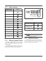
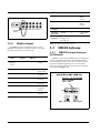
026-1307 Rev 4 28-JUN-2011 Modular Refrigerant Leak Detection Sensor (MRLDS) Installation and Operation Manual Retail Solutions 3240 Town Point Drive NW, Suite 100 Kennesaw, GA 30144, USA Phone 770-425-2724 Fax 770-425-9319 ALL RIGHTS RESERVED The information contained in this manual has been carefully checked and is believed to be accurate. However, Computer Process Controls, Inc. assumes no responsibility for any inaccuracies that may be contained herein. In no event will Computer Process Controls, Inc. be liable for any direct, indirect, special, incidental, or consequential damages resulting from any defect or omission in this manual, even if advised of the possibility of such damages. In the interest of continued product development, Computer Process Controls, Inc. reserves the right to make improvements to this manual, and the products described herein, at any time without notice or obligation. FCC COMPLIANCE NOTICE This device complies with Part 15 of the FCC Rules. Operation is subject to the following two conditions: (1) this device may not cause harmful interference, and (2) this device must accept any interference received, including interference that may cause undesired operation. TABLE OF CONTENTS 1 OVERVIEW ............................................................................................................................................. 1 1.1 SPECIFICATIONS ................................................................................................................................................. 1 1.2 MRLDS MODELS ............................................................................................................................................... 1 1.3 POWERING THE MRLDS ..................................................................................................................................... 1 2 CHOOSING A MOUNTING LOCATION ....................................................................................................... 2 2.1 MOUNTING THE SENSOR ..................................................................................................................................... 2 2.2 MRLDS DIMENSIONS ......................................................................................................................................... 3 3 E2 MODBUS DIRECT SUPPORT FOR MRLDS .............................................................................................. 3 3.1 NETWORK CONNECTION TO E2............................................................................................................................. 3 3.1.1 COM Port Associations - E2 Versions 3.xx and Below ......................................................................................... 3 3.1.2 COM Port Associations - E2 Versions 4.0 and Above........................................................................................... 4 3.1.3 E2 Termination ...................................................................................................................................................... 4 3.2 E2 SETUP OF MRLDS ......................................................................................................................................... 4 3.2.1 Set Up Network Ports............................................................................................................................................. 4 3.2.2 Add and Connect MRLDS ...................................................................................................................................... 5 4 MRLDS ANALOG VERSION (809-100X)..................................................................................................... 6 4.1 NETWORK LAYOUT ............................................................................................................................................. 6 4.2 MRLDS WIRING................................................................................................................................................ 6 4.3 REFRIGERANT JUMPER SETTINGS ............................................................................................................................ 6 4.4 CONTROLLER SETUP FOR ANALOG MRLDS ............................................................................................................. 7 4.4.1 E2 Controllers Version 2.5 and Newer.................................................................................................................. 7 4.4.2 Einstein/E2 Controllers Prior to Version 2.5 ........................................................................................................ 7 4.4.3 RMCC Controllers ................................................................................................................................................. 7 5 MRLDS GATEWAY VERSION (809-101X) .................................................................................................. 8 5.1 NETWORK LAYOUT ............................................................................................................................................. 8 5.2 MRLDS SETUP .................................................................................................................................................. 8 5.2.1 MRLDS Wiring....................................................................................................................................................... 8 5.2.2 MRLDS Network Addressing ................................................................................................................................. 8 5.2.3 Address Settings ..................................................................................................................................................... 9 5.2.4 Refrigerant Jumper Settings................................................................................................................................... 9 5.2.5 MRLDS Termination .............................................................................................................................................. 9 5.2.6 Modbus Output..................................................................................................................................................... 10 5.3 MRLDS GATEWAY ........................................................................................................................................... 10 5.3.1 MRLDS Gateway Setup on I/O Network..................................................................................................................................................................... 10 5.3.2 Gateway Connections .......................................................................................................................................... 11 5.3.3 The Gateway Board ............................................................................................................................................. 11 5.3.4 Powering the Gateway Board .............................................................................................................................. 11 5.3.5 Connecting the Gateway Board to the Einstein or REFLECS Network .............................................................. 11 5.3.6 Wire Connections................................................................................................................................................. 12 5.3.7 Termination Settings ............................................................................................................................................ 12 5.3.8 Gateway Board I/O Net Addressing..................................................................................................................... 12 5.3.9 Setting the Baud Rate Dip Switches..................................................................................................................... 13 5.3.10 Hand-Held Terminal Settings ............................................................................................................................ 13 5.3.10.1 MRLDS Setup......................................................................................................................................................... 13 5.3.10.2 Select Screen........................................................................................................................................................... 13 MRLDS I&O Manual Table of Contents • v 5.3.10.3 Status Screen........................................................................................................................................................... 13 5.3.10.4 Setup/Online Screen................................................................................................................................................ 14 5.3.10.5 Firmware Revision Screen...................................................................................................................................... 14 5.3.11 Gateway Troubleshooting .................................................................................................................................. 14 5.4 CONTROLLER SETUP FOR MODBUS MRLDS ........................................................................................................... 14 5.4.1 Mapping The MRLDS as an IRLDS Application ................................................................................................. 14 5.4.2 Designating MRLDS as a 16AI Board ................................................................................................................. 14 5.4.3 E2/Einstein Controllers........................................................................................................................................ 15 5.4.4 RMCC Controllers Version 2.1 and Newer ......................................................................................................... 15 5.4.4.1 REFLECS Setup for IRLDS IIs................................................................................................................................ 15 5.4.5 BEC and RMCC Controllers Less Than Version 2.1 ........................................................................................... 16 5.4.5.1 5.4.5.2 5.4.5.3 5.4.5.4 Input Definitions ....................................................................................................................................................... Sensor Setup.............................................................................................................................................................. Sensor Setpoints........................................................................................................................................................ Alarm Setpoints ........................................................................................................................................................ 16 16 16 17 6 DIAGNOSTICS ....................................................................................................................................... 17 6.1 MRLDS LED INDICATORS .................................................................................................................................. 17 6.2 E2 ALARMING .................................................................................................................................................. 17 6.2.1 IRLDS Mode......................................................................................................................................................... 17 6.2.2 16AI Mode ............................................................................................................................................................ 17 6.3 LINEARITY SETTINGS FOR SUPPORTED REFRIGERANTS................................................................................................ 18 vi • Table of Contents 026-1307 Rev 4 28-JUN-2011 1 Overview Retail Solutions specs a modular refrigerant leak detection sensor (MRLDS) that continuously monitors for low levels of refrigerants most commonly used in commercial refrigeration systems. The MRLDS communicates with the E2 controller via direct connect MODBUS, a Gateway board connected to the RS485 I/O Network, or via the analog input on a MultiFlex board. 1.1 Specifications Power Requirements 24 VAC, ±20%, 50/60 Hz, Class 2 Wiring 14 AWG max, Class 2 copper wiring Power Consumption Less than 2.7 watts Output Options 1-5V, 10 K Ohm load RS485 Modbus RTU Operating Temp. 32 to 149°F (-22 to 149°F with de-icer*) 0 to 65°C (-30 to 65°C with de-icer*) Humidity 0 to 99% non-condensing Size 4.5” x 3.5” x 1.6” Weight .35 lbs. (160 g) Pollution Degree 2 Installation Category II Range 0 to 1000 PPM Minimum Detection 25 PPM Pressure Operating 10.2 to 15.7 PSIA Repeatability ±10 PPM at 50 PPM Linearity See Table 6-2, “- Linearity Settings for Supported Refrigerants,” on page 18 Warm-up Time 30 minutes Table 1-1 - MRLDS Unit Specifications *De-icer: for environments below 32°F to keep ice from forming on the surface of enclosure. Specifications Figure 1-1 - Sensor Base Opening With Screw Terminals 1.2 MRLDS Models Part Number Description 809-1000 Voltage Out w/o de-icer* 809-1001 Voltage Out with de-icer* 809-1010 Modbus w/o de-icer* 809-1011 Modbus with de-icer* Table 1-2 - Available MRLDS Models 1.3 Powering The MRLDS Part Number Transformer Description Number of MRLDS Units Powered 640-0039 24VAC, 10VA Class 2 Up to 3 Table 1-3 - MRLDS Transformer Specifications The MRLDS unit requires a separate UL Listed/CSA Certified 24VAC Class 2 transformer power supply. One 24VAC, 10VA Class 2 transformer is sufficient for up to three (3) MRLDS units. Retail Solutions supplies several sizes of transformers for powering multiple MRLDS units (three or more). Note that polarity must be maintained when connecting more than one MRLDS to a single transformer. WARNING: The MRLDS unit must be always be powered by either a suitable UL 60950/CSA Certified power supply that is isolated from line voltage by double insulation, or an appropriately rated UL Listed/CSA Class 2 transformer. Failure to follow the above can result in serious personal injury or death. Overview • 1 If a transformer is shared between MRLDS units, the “ACN” of each MRLDS must be wired to the same phase of the transformer. 120VAC Tr MRLDS I MRLDS II er 24VAC rm o sf an ACN Figure 1-2 - Powering Multiple MRLDS Units 2 Choosing a Mounting Location Figure 2-1 - Sensor Base And Cover 2.1 Mounting The Sensor The refrigeration monitor comprises two basic parts: the base and the cover. The cover incorporates the circuit board with the sensing elements. Proper location of the refrigerant sensor is necessary to ensure accurate measurement of representative air samples. 1. Fasten the base to a junction box or other support. The base has a number of openings to allow for mounting to various junction boxes. Mount the sensor: • Indoors, inside a room area where air circulates freely. 2. Feed the power and signal wires through the rectangular opening in the base (Figure 1-1). 3. Connect the wires to the terminal connector located in the base, as indicated in Figure 5-2 and Figure 4-2. 4. The Modbus MRLDS must be connected to earth ground. Connect earth ground to the MRLDS • On a flat, interior surface. • Approximately 12-18 inches (30-45 cm) from the floor. Do not mount the sensor: • On surfaces in unheated areas (less than 0°C), unless using a model with a de-icer.* ground terminal labeled . Connect to earth ground with 14 AWG wire that is less than 6 inches. • Near heat sources, such as appliances, direct sunlight, or concealed pipes or chimneys. 5. Align the two side tabs of the cover with the base and snap the cover onto the base. • On walls subject to excessive vibration. 6. • In the direct path of an exhaust fan. Excessive air movement will disperse gas before it can be detected. If mounting in the path of excessive airflow cannot be avoided, it will be necessary to turn OFF air circulation for 1/4 to 1/2 hour, 4-6 times a day. Verify the cover is securely attached to the base by pulling on the top and bottom of the cover as shown in Figure 2-2. NOTE: For example, if mounted inside a motor room, exhaust fans must be shut off during the intervals that air samples will be tested for refrigerant levels. 2 • MRLDS I&O Manual NOTE: To remove the cover, grasp it along the recesses and pull it away from the base (Figure 2-2). Alternatively, place a screwdriver into the slots indicated in Figure 2-2 and twist. 026-1307 Rev 4 28-JUN-2011 3 E2 MODBUS Direct Support for MRLDS 3.1 Network Connection to E2 Figure 2-2 - Attaching and Removing Cover 2.2 MRLDS Dimensions Connecting an MRLDS to an E2 unit requires the E2 version 3.01 and above. Contact Retail Solutions for upgrade information if the controller is a version prior to 3.01. 3.1.1 COM Port Associations - E2 Versions 3.xx and Below Figure 3-1 - Location of E2 COM Ports - E2 PIB Board (E2 version 3.xx and below) Figure 2-3 - MRLDS Mounting Dimensions MRLDS Dimensions An E2 has up to three COM ports that can be assigned for MODBUS communication (COM2, an RS485 port on the E2 power interface board, and COM4 and COM6, which are optional ports requiring expansion cards). COM ports can only be used for one function; in other words, if COM2 is set up as the I/O network, you cannot connect MODBUS devices to COM2. Ensure your E2 is equipped with an RS485 COM Card (P/N 637-4890) and configured E2 MODBUS Direct Support for MRLDS • 3 in E2 General Services (, Serial tab) to enable COM4 or an E2 Expansion COM Card (P/N 6374871) to enable COM6. Connect the MODBUS network cable to the three-terminal connector on the COM port you wish to assign as MODBUS. Wire RS485+ to the MRLDS+ RS485- to the MRLDS- and the shield cable to the MRLDS GND. 3.1.2 COM Port Associations - E2 Versions 4.0 and Above not the first device. For E2 versions 4.0 and above, if the E2 is the beginning of all RS485 I/O or MODBUS Networks, all three of these jumpers should be set to the UP position. For MODBUS, the jumpers should all be in the top-most position (MOD). For I/O Net, the jumpers should be in the middle position (I/O). For no termination, set the jumpers to the down position (NO). E2 E2 PIB COM PORT ASSOCIATIONS E2 Enclosure (Right Side) + - COM1 MODBUS Serial Device RS232 Port Plug-In Modem Card COM3 MRLDS + - MRLDS + - MRLDS Figure 3-3 - MRLDS MODBUS Network Layout Serial Device RS485 COM Ports COM6 MRLDS (Up to 12 MRLDS units on the network) POWER INTERFACE BOARD (PIB) COM2 + + - COM4 Figure 3-2 - Location of E2 COM Ports - E2 PIB Board (E2 version 4.0 and above) An E2 has three COM ports that can be assigned for MODBUS communication (COM2). COM ports can only be used for one function; in other words, if COM2 is set up as the I/O network, you cannot connect MODBUS devices to COM2. Ensure your E2 is configured in E2 General Services (, Serial tab) to enable COM4 or COM6. 3.2 E2 Setup of MRLDS 3.2.1 Set Up Network Ports Before setting up a MRLDS, the port on the E2 that has the MODBUS cable connected must be set up as a MODBUS port. 1. Log in to the E2 with Level 4 access. 2. Press followed by - General Controller Info. 3. Press + to open the Serial tab of the General Controller Info setup screens: Connect the MODBUS network cable to the three-terminal connector on the COM port you wish to assign as MODBUS. Wire RS485+ to the MRLDS+ RS485- to the MRLDS- and the shield cable to the MRLDS GND. 3.1.3 E2 Termination For E2 versions 3.xx and below, if the E2 will be the first device in the daisy-chain, set the port’s termination jumpers to the TERMINATED & BIASED position (all three jumpers UP); otherwise, set all jumpers DOWN if 4 • MRLDS I&O Manual 026-1307 Rev 4 28-JUN-2011 Boards and Controllers. Figure 3-4 - Serial Communications Manager Screen 4. 5. This screen will have a “Connection” field for all COM ports on the E2. Highlight the COM port connection field that will be used, and press - LOOK UP. From the list of network types, select MODBUS. Four fields will become visible underneath the COM port connection field, which pertain to the way the device communicates: Figure 3-5 - Connected I/O Screen 3. 4. On the ECT tab screen enter the number of MRLDS Panels in the MRLDS number field. Press to return to the Network Setup menu, then select - Network Summary (Figure 3-6). 5. •Baud - Default setting is 19200. Leave this field at the default value. Locate the MRLDS you added to the network list (press and to scroll through the list) and highlight with the cursor. Press for Setup. •Data Size - Leave this field at the default value (8). •Parity - Leave this field at the default value (None). •Stop Bits - MRLDS value is two (2). 6. 3.2.2 Press to save changes and exit. Add and Connect MRLDS To enable communications between E2 and the MRLDS, the devices must be added and addressed in E2. 1. Log in to the E2 with Level 4 access. 2. Press - Connected I/O Figure 3-6 - Network Summary Screen Each MRLDS is assigned a MODBUS address automatically when it is created. 6. E2 Setup of MRLDS Locate the MRLDS you set up, and look at each device’s status in the Status field. You E2 MODBUS Direct Support for MRLDS • 5 4 MRLDS Analog Version (809-100x) 4.1 Network Layout Analog MRLDS to MultiFlex MULTIFLEX BOARD LOWER RIGHT CORNER ACN 24VAC GAS(+) OUT(V) ANALOG MRLDS INSIDE LOWER PORTION OF BASE 1 3 2 0V 0V SIG BELDEN 8761 4 SIG INPUT 14 OUT(V) TO 24VAC, 10VA CLASS 2 POWER SUPPLY Ground INPUT 13 SIG 0V Ground will see one of the following messages: •Online - The MRLDS is communicating normally. •Offline - The MRLDS is not communicating, has not been commissioned, is not functional, or is not powered up. Verify the MRLDS is powered up, wired correctly, and has the proper network address, baud rate, and parity. •No Port - No port is set up in the E2 Serial Configuration Manager to be a MODBUS port. 5 0V 6 SIG INPUT 15 7 0V 8 SIG INPUT 16 A transformer must never be shared between MRLDS and the MultiFlex BELDEN board. A separate 8761 transformer must be used. If a transformer is shared between MRLDS units, the “ACN” of each MRLDS must be wired ). to the same phase of the transformer. EARTH SHIELD NEAR THE MULTIFLEX BOARD. DO NOT CONNECT THE SHIELD TO THE 0V INPUT ON THE MULTIFLEX BOARD. Wire MultiFlex SIG to MRLDS OUT(V). Wire MultiFlex 0V to MRLDS Ground ( Figure 4-2 - Analog MRLDS Wiring E2 I/O Net r vic he Ot t De To Ne O I/ es MultiFlex Board MRLDS Units Figure 4-1 - Analog MRLDS Network Layout Example 4.2 MRLDS Wiring For analog MRLDS units, connect to a MultiFlex board via the analog input (use Belden 8761 cable). 4.3 Refrigerant Jumper Settings The jumper settings for refrigerant types are located on the label inside the MRLDS sensor cover (shown in Figure 1-1). Set the jumpers according to how they are indicated on the label. The MRLDS supports ten different refrigerant types. Select the desired refrigerant type by setting one jumper to the J2 or J1 sockets (Figure 2-1) respective per the inside label. Analog Jumpers J2 J1 J2 J1 refrigerant type jumpers Figure 4-3 - Analog Jumper Layout (Inside Lower Portion of Cover) Enlarged To Show Detail 6 • MRLDS I&O Manual 026-1307 Rev 4 28-JUN-2011 7. Refrigerant Type J2|J1 Manually enter the following parameters on the Input Setup screen: •Sensor Type: Linear R-22 •Low End Point: 0.8V •Low Eng. Units: -50 R-134a, R-407A, R-407C, R-410A, R-427A •Select Eng. Units: PPM •HighEnd Point: 5.5V R-404A, R-422A, R-422D, R-507 •High Eng. Units: 1125 •Low End Limit: -100 Table 4-1 - Refrigerant Jumper Settings •HighEnd Limit: 1150 4.4 Controller Setup For Analog MRLDS 4.4.1 E2 Controllers Version 2.5 and Newer 1. Log in to the E2 controller. 2. Press the Menu button to open the Main Menu. 3. Select 7. System Configuration. 4. Select 1. Input Definitions. 5. Select the board/point input. 6. Press F1 Setup. 7. Select Analog Sensor. 8. On the Analog Input screen, select MRLDS Refr. as the Sensor Type. The parameters are then automatically configured for you. 9. Press the (Back) button to save changes. If the device is configured and powered correctly, a value will be visible under the Value column on the Input Status screen. 4.4.2 Einstein/E2 Controllers Prior to Version 2.5 For Einstein and E2 controllers prior to version 2.5, follow the steps below, set the sensor type to Linear, and manually enter the parameters: 1. Log into the E2 controller. 2. Press the Menu button to open the Main Menu. 3. Select 7. System Configuration. 4. Select 1. Input Definitions. 5. Select the board/point input. 6. Press F1 Setup. Controller Setup For Analog MRLDS (Set the alarm failure to < -10PPM.) 8. Press the (Back) button to save changes. If the device is configured and powered correctly, a value will be visible under the Value column on the Input Status screen. Figure 4-4 - Analog Input Screen Settings Example for E2 4.4.3 RMCC Controllers For RMCC-type controllers, set the Gain parameter to 250 and Offset to -1000. MRLDS Analog Version (809-100x) • 7 5 MRLDS Gateway Version (809-101x) 5.1 Network Layout 5.2.2 MRLDS Network Addressing Modbus network settings are set on jumpers J5, J4, and J3. Refer to Table 5-1 (also included on the inside label of the MRLDS) for network addressing with corresponding jumper settings. If more than one MRLDS is on the network, each unit must have a unique address and be numbered according to the inside label (Table 5-1) specifications. E2 + - I/O Net J6 - + J1 Gateway MODBUS + + - MRLDS MRLDS + - MRLDS + - MRLDS (Up to 12 MRLDS units on the network per Gateway) J6 J5 J4 J3 J2 J1 term jumper network address jumpers refrigerant type jumpers Figure 5-3 - MRLDS Jumpers (Inside Lower Portion of Cover) Figure 5-1 - Network Layout Example 5.2 MRLDS Setup 5.2.1 MRLDS Wiring MODBUS NETWORK BELDEN 8761 To Gateway Board EARTH GND ACN 24VAC RS485 (-) RS 485 (+) MODBUS MRLDS - INSIDE LOWER PORTION OF BASE 14 AWG less than 6 inches Shield drain/ground wire A transformer must never be shared between MRLDS and the Gateway board. A separate transformer must be used. If a transformer is shared between MRLDS units, the “ACN” of each MRLDS must be wired to the same phase of the transformer. Figure 5-2 - Modbus MRLDS Wiring 8 • MRLDS I&O Manual 026-1307 Rev 4 28-JUN-2011 5.2.3 Address Settings Modbus Address Jumper Settings J5|J4|J3 100 J6 J1 No jumpers installed J6 J5 J4 J3 J2 J1 term jumper 101 network address jumpers refrigerant type jumpers 102 103 Figure 5-4 - Modbus Jumper Layout (Inside Lower Portion of Cover) Enlarged To Show Detail 104 105 Refrigerant Type J2|J1 R-22 106 R-134a, R-407A, R-407C, R-410A, R-427A 107 108 R-404A, R-422A, R-422D, R-507 Table 5-2 - Refrigerant Jumper Settings 109 110 NOTE: When using the MRLDS Gateway, it will only show the base refrigerant type selections (R-22, R-134a, R-404A). 111 Table 5-1 - MRLDS Modbus Address Jumper Settings 5.2.4 Refrigerant Jumper Settings The jumper settings for refrigerant types are located on the label inside the MRLDS sensor cover (shown in Figure 1-1). Set the jumpers according to how they are indicated on the label. 5.2.5 MRLDS Termination The MRLDS has a built-in, on-board means of termination, so an external termination block is not necessary for terminating. When the device is located at the end of a daisy chain, set jumper JP6 for termination. The MRLDS supports ten different refrigerant types. Select the desired refrigerant type by setting one jumper to the J2 or J1 sockets respective per the inside label. MRLDS Setup MRLDS Gateway Version (809-101x) • 9 Factory Mode 4 (Lsb) J6 Trouble Mode 8 (Lsb) J1 Termination jumper J6 J5 J4 J3 J2 J1 Figure 5-5 - MRLDS Termination (Inside Lower Left of Cover) 5.2.6 Modbus Output Fault and Module State PDU Address 0x0000 Logical Address 1 0x0001 2 0 to 40 Gas Concentration 0x0002 3 -20 to 1050 (PPM) Gas Numbers R-22 = 6 R-404A = 27 R-134a = 15 Table 5-3 - RS485 Output Specifications See Table 5-3 below for Modbus registers in the MRLDS Unit. Baud rate: 19,200; each byte is 8 (eight) bits with no parity and 2 (two) stop bits. Register Name Gas Number Range Under Range 2 (msb) 5.3 MRLDS Gateway 5.3.1 MRLDS Gateway Setup on I/O Network Modbus versions of the MRLDS must be connected to the 810-3040 MRLDS Gateway. The MRLDS Gateway can be mapped in either of two ways: it can be set up on I/O Net as an IRLDS application or as a 16AI board. Select by setting the Gateway’s dip switch #5 to the OFF or ON position (Figure 5-6). Under Voltage 8 (msb) Temperature 10 (msb) Lamp Fail 40 (msb) Test Mode 80 (msb) Warm Up Complete 0 (Lsb) SELECT I/O NET MODE OFF = IRLDS ON = 16AI ON Cal/Setup 2 (Lsb) Table 5-3 - RS485 Output Specifications OFF = IRLDS ON = 16AI Figure 5-6 - I/O Network Modes 10 • MRLDS I&O Manual 026-1307 Rev 4 28-JUN-2011 5.3.2 Gateway Connections Up to 12 MRLDS units may be connected to the Gateway board (P/N 810-3040). The Gateway board can interface with a site controller as a 16AI or as an IRLDS. If the site controller is an Einstein or E2, it is recommended to interface them as an IRLDS. Multiple Gateways can be used, each with up to 12 connected MRLDS units. 5.3.3 The Gateway Board Class 2 center-tapped transformer. Retail Solutions supplies several sizes of center-tapped transformers for powering multiple 16AIs, 8ROs, and other RS485 peripheral boards. Figure 5-8 shows how to connect the 56VA and 80VA transformers to the Gateway power connector. Three-Board P/N Power Rating Six-Board 640-0056 640-0080 56 VA 80 VA Table 5-5 - Power Ratings for CPC Transformers Figure 5-7 - MRLDS Gateway Board Layout (810-3040) CAUTION: Before installing the Gateway board, verify the jumper JP7 (located near the top center of the board) is set to the “NORMAL” position (not the “TEST” position). Operating the Gateway with the jumper in “TEST” position may cause board damage. The Gateway Board communicates with the MRLDS via the Modbus network, which is connected to the Gateway’s “Receiver Bus” network terminal. The Gateway communicates with the E2 via the RS485 I/O Network. 5.3.4 Board Powering the Gateway Input Voltage 24VAC, Class 2, Center-Tapped 50/60Hz Power 5VA Figure 5-8 - Pinout for the 56VA (640-0056) and 80VA (6400080) Transformers CAUTION: The MRLDS unit requires a separate Class 2, 24VAC, 10VA power supply. 5.3.5 Connecting the Gateway Board to the Einstein or REFLECS Network Each E2, Einstein, or REFLECS site controller that will communicate with one or more MRLDS units must have a Gateway Board installed on its RS485 I/O Network. For Einstein controllers, this means the Gateway will be installed on the RS485 I/O Network; for RMCC, BEC, BCU, and other REFLECS products, the Gateway will be installed on the COM A or COM D network. Table 5-4 - Gateway Power Requirements The Gateway board requires 24VAC power from a MRLDS Gateway MRLDS Gateway Version (809-101x) • 11 5.3.6 Wire Connections Using shielded three-conductor network cable (Belden #8641 or equivalent), connect the RS485 I/O Network wire to the three-terminal connector on the Gateway board as shown in Figure 5-9. For further information about how RS485 networks are configured, refer to your site controller’s user manual. To terminate the Gateway (the Modbus jumpers should always be terminated on the Gateway), set the receiver bus jumpers to the RIGHT position (Figure 5-11). RS485 I/O NET TERM JUMPERS RS485 I/O NET (TO CPC CONTROLLER) TERMINATION GATEWAY BOARD (ALWAYS TERMINATE) -485 0v +485 Figure 5-11 -MRLDS Gateway Termination Figure 5-9 - Connecting the Gateway to the E2 RS485 Network To connect the Gateway to an MRLDS, feed the wires through the rectangular opening in the sensor base as indicated in Figure 1-1. Locate the RS485 connector and secure the wire leads to the connector orienting them as shown in Figure 5-10. Connect multiple MRLDS units in a daisy-chain configuration as shown in Figure 5-1. 5.3.8 Gateway Board I/O Net Addressing Set the address on the I/O Network with switches 1-4. There can be more than one MRLDS Gateway with each supporting up to 12 MRLDS units. Switch 5 indicates whether the MRLDS will be mapped as an IRLDS or 16AI. Set switch 5 to the OFF position for IRLDS emulation or to the ON position for 16AI emulation. To MRLDS MODBUS GATEWAY BOARD -485 0v +485 MRLDS - INSIDE LOWER PORTION OF BASE Shield drain/ ground wire I/O NET MODE ON = 16AI OFF = IRLDS -485 MODBUS NETWORK EARTH GND ACN 24VAC B RS 485RS 485+ A 0v +485 ADDRESS ON I/O NET Shield drain/ground wire Figure 5-10 - Connecting the Gateway to MODBUS 5.3.7 Termination Settings As part of a site controller’s RS485 I/O (COM A or COM D) Network, a Gateway must be terminated if it is the end device of a daisy chain. The Gateway on the Modbus Network should always be terminated and always located at the end of the daisy chain. Refer to the site controller’s user manual for information about daisy chain networks and how they are terminated. 12 • MRLDS I&O Manual 15 14 Figure 5-12 - Network Layout Example 026-1307 Rev 4 28-JUN-2011 5.3.9 Setting the Baud Rate Dip Switches Dip switches 6 and 7 control the baud rate at which the Gateway communicates with the site controller on the RS485 Network. These switches must be set to the same baud rate setting as the controller you are using (Einstein, RMCC, or E2), and defaults to 9600 baud. Dip switch 8 controls the baud rate at which the Gateway communicates with the MRLDS. For 9600 baud, set dip switch 8 to the OFF position. For 19200 baud, set dip switch 8 to the ON position (always use 19200 baud for MRLDS). I/O ADDR: I/O BAUD: MOD BAUD: FAIL I/O NETWORK OR COM A AND D BAUD RATE (GW to E2) 1 2 3 4 5 6 7 8 ON OFF = 9600 BAUD ON MODBUS ON = 19200 BAUD ON MODBUS (GW to MRLDS) I/O NET BAUD RATE SETTINGS 9600 19200 ALWAYS USE 19200 BAUD WITH MRLDS I/O NET Figure 5-15 - Baud Rate/Address Screen The Baud Rate/Address screen displays the Gateway I/O Network address (I/O ADDR), the I/O Network baud rate between the Gateway and the E2 (I/O BAUD), and the Modbus baud rate between the Gateway and the MRLDS devices (MOD BAUD). 5.3.10.2 GATEWAY DIP SWITCH 1 9600 19200 Select Screen Press the down arrow again to navigate to the Select screen (or press F2). From the Select screen you can see status, setup, and firmware version information. To select, press the right arrow until it appears next to SELECT and press 1, 2, or 3 in the list. Press the down arrow twice to move to the desired screen. SELECT: 1 1 - STATUS 2 - SETUP/ONLINE 3 - FW REVISION FAIL I/O NET Figure 5-16 - Select Screen Figure 5-13 - Dip Switch Settings for Gateway Baud Rate 5.3.10 Hand-Held Terminal Settings The hand-held terminal can be used to view status information, enable unit addresses, and is connected directly to the Gateway board via the hand-held terminal jack. MRLDS GATEWAY 810-3040 VER:1.10B03 ( PRESS ) FAIL I/O NET 5.3.10.3 Status Screen 1 - The Status screen displays general status information about the MRLDS such as device numbering, count information (gas concentration in PPM), the type of refrigerant gas being monitored (MRLDS jumpers set by the user), and whether an alarm has been issued. An alarm indicates an MRLDS failure and that the MRLDS should be replaced. Call the Retail Solutions Service Department (770-425-2724) to verify if the MRLDS unit should be replaced. Possible states (ST) are: • WARMUP - MRLDS is warming up. • NORMAL - MRLDS has completed warm-up and is operating normally. Figure 5-14 - MRLDS HHT Home Screen • OFFLINE - MRLDS has lost communication. 5.3.10.1 • UNUSED - This address is not being used. MRLDS Setup From the HHT Home screen (F1), press the down arrow key to navigate to the Baud Rate/Address screen (Figure 5-15). MRLDS Gateway • FAIL - MRLDS has reported a fail state. Check the ALM field for specification. MRLDS Gateway Version (809-101x) • 13 5.3.11 Gateway Troubleshooting 100: GAS: ST: ALM: FAIL CNT: 1 R134A NORMAL NONE I/O NET Figure 5-17 - Status Screen NOTE: If the HHT displays any type of alarm, contact the Retail Solutions Service Department (770-425-2724) to verify if the MRLDS unit should be replaced. 5.3.10.4 Setup/Online Screen 2 - The Setup/Online screen displays the addressing of the devices and whether they are enabled. Press the right/ left arrows to select the first address in the list. Toggle the minus button to enable the first address in the list (Figure 5-18). If communication is established, the screen will show “ON-L” indicating the unit is set up and online. 100: ENBLE ON-L 102: :: 103 104: FAIL I/O NET Figure 5-18 - Setup/Online Screen NOTE: For IRLDS mode, disable unused addresses by toggling the minus key to DISABLE. Unused addresses that have not been disabled may cause a false failure on the E2. 5.3.10.5 Firmware Revision Screen 3 - The Firmware Revision screen displays the address of the MRLDS unit with its associated firmware revision. 100: 102: 103: 104: FAIL ENABLE 1.12 ---------------I/O NET Figure 5-19 - Firmware Revision Screen 14 • MRLDS I&O Manual If there is an issue with the Gateway board, the HHT Home screen (F1) can give status indicators to report the issue. The Home screen will display a warning if there is a failure associated with the I/O Network or flash on the Gateway board. Select the HHT Status screen to view status information for each MRLDS unit. 5.4 Controller Setup for Modbus MRLDS 5.4.1 Mapping The MRLDS as an IRLDS Application To set up communication on the I/O Network as an IRLDS application: 1. Log in to the E2 controller. 2. Press the Menu button to open the Main Menu. 3. Select 7. System Configuration. 4. Select 7. Network Setup. 5. Select 2. Connected I/O Boards & Controllers and add the desired number of MRLDS Gateways as IRLDS under I/O Net Devices. Up to 12 units can be connected to each Gateway. 6. Press the (Back) button and select 1. Online Status (Alt + N) to check the status. 7. Go into the IRLDS application under General Setup and add the number of MRLDS units (Num Channels field) connected to the Gateway. 5.4.2 Designating MRLDS as a 16AI Board 1. Log in to the E2 controller. 2. Press the Menu button to open the Main Menu. 3. Select 7. System Configuration. 4. Select 7. Network Setup. 5. Select 2. Connected I/O Boards & Controllers and add the desired number of 16AI boards under I/O Net Devices. 6. Press the (Back) button and select 1. Online Status (Alt + N) to check the status. For mapping the MRLDS unit as a 16AI board, first set dip switch #5 on the Gateway board to the ON position. Follow Steps 1-6 above, but for Step 6 select the number of 16AI boards to equal the number of MRLDS Gate- 026-1307 Rev 4 28-JUN-2011 5.4.4 ways. Navigate to the controller’s Input Status screen and highlight the board and point that you wish to map. Press F1 to go to the Input Setup screen for that board/point. Each point will increase incrementally to correspond with each board. (For example, where the MRLDS is address 1 and the MRLDS address is 100, use board 1, point 1. For an MRLDS address of 101, use point 2.) 5.4.3 E2/Einstein Controllers Next, set up the following parameters on the Input Setup screen: • Sensor Type: Linear • Low End Point: 0.00000 • Select Eng. Units: PPM • HighEnd Point: 4.80000 RMCC Controllers Version 2.1 and Newer 5.4.4.1 REFLECS Setup for IRLDS IIs Set dip switch 8 to ON and follow the steps for setting up IRLDS IIs through the REFLECS controller interface: 1. Log on. 2. Press 7 for Configuration to reach the CONFIGURATION screen. Input Definitions should be set here to show how the sensor control is linked to the zone. The number of devices and IRLDS IIs are connected to the Gateway and enabled is the number of address slots the Gateway will use. 3. Press 1 for Input Definitions to reach the INPUT DEFINITIONS screen. 4. Pressing the down arrow several times will get you to the input list of SENS01-48. Bd (board) is the address of the Gateway, Pt (point) is the zone and allows you to define where the sensor input comes from. • High Eng. Units: 1200.0000 The board number for the IRLDS II setup is the address of the Gateway. If there are three or less IRLDS II controllers connected to a Gateway, the Gateway address = the IRLDS II address. However, if there are more than three IRLDS controllers, the second Gateway address will be the one entered for the board number, but the IRLDS II controllers are set 1 to 3 on the second Gateway. Figure 5-20 - Analog Input Screen Settings Example for E2 5. Press 0 (zero) to go back to the CONFIGURATION screen. 6. Press 7 for I/O Brd Setup to reach the I/O BOARD MENU screen. 7. Press 2 to Set Device #’s. The Gateway will react as three 16AI boards. The number of IRLDS II controllers plus the real number of 16AIs = the total number of 16AIs to enter in the next step: 8. At the I/O BOARD DEVICE NUMBERS screen, press the down arrow key to reach Number 16AI Boards and enter the number of how many 16AI boards and IRLDS II controllers there are. Press Enter. 9. Arrow down to the I/O BOARD MENU and press 0 (zero) twice to go back to the MAIN MENU screen. 10. Press 4 for Sensor Control. 11. Press 2 for Setup--up to 48 sensor control programs are allowed. Select one of the 48 units and press Enter to reach the SENSOR SETUP screen. 12. Press the right arrow to move to the Name Controller Setup for Modbus MRLDS MRLDS Gateway Version (809-101x) • 15 field to change the name, and press the down or right arrow to move to the (sensor) Type field. Use the “.” and “—” keys to scroll through the options and select IRLDS. (The Gain and Offset parameters are automatically configured for you.) 13. Use the arrow keys to move off the active fields and press 0 (zero) twice to go back to the main screen. 5.4.5 5.4.5.1 BEC and RMCC Controllers Less Than Version 2.1 Input Definitions Locate the screen in the BEC or RMCC where sensors are set up. This is usually a menu option in the Sensors Menu, which may be reached from the Main Menu. The 0-4.8V signal is a linear signal representing a measured concentration of 0-1200 PPM, and a voltage of 5.0V indicates a fault. In order for the REFLECS to read these voltages correctly, the REFLECS sensor inputs must be configured as linear sensors. Name A name for the sensor input may be entered in the Name field. Since each IRLDS zone is set up with two REFLECS sensor inputs, choose names for each input that distinguish the input’s function. For example, the sensor input set up to read leak concentrations on zone 1 should have a name like REFR LK ZN 01, and the input set up to monitor fault status should have a name like FAULT ZN 01. Type All sensor inputs connected to an IRLDS should be set up as linear sensors. Enter (L)inear in the Type field. Logging Interval Locate the screens in the BEC or RMCC that are used to define input board and points. This is usually achieved by pressing 7 then 1 from the Main Menu. Press the DOWN ARROW key several times until the SENS01SENS08 inputs are shown. The 16AI connected to the IRLDS’s output terminals must be set up in the REFLECS’s system software. If the 16AI was given a unique board number by setting the dip switch S3, and wired to the terminals so that each zone number corresponds to a 16AI point number (zone 01 connected to point 01, for example), these board and point addresses must now be entered into the REFLECS. The logging interval is the amount of time between log entries in the REFLECS’s Data Log. When choosing a logging interval, keep in mind the amount of time it takes an IRLDS to go through an entire cycle of samplings. For example, a 16-valve IRLDS with 30 second sampling times for each zone takes a total of eight minutes to sample all zones. Choosing a logging interval smaller than the IRLDS’s cycle time will simply clutter the REFLECS data log with multiple copies of the same sample. 5.4.5.3 Sensor Setpoints The screen above shows how the board and point addresses for zone 1 would be set up for a 16AI board numbered 1. Both SENS01 and SENS02 are set up as 01:01 so that SENS01 can monitor concentration and SENS02 can monitor fault status. Set up the remaining sensors using the instructions given above. For each point on the 16AI, set up two sensors with the same addresses. 5.4.5.2 Sensor Setup Locate the screen in the BEC or RMCC where sensor set points are specified. This is usually a menu option in the Sensors Menu, which may be reached from the Main Menu. After the linear sensors have been set up, the REFLECS must be told how to interpret the linear voltage given by the IRLDS. Eng. Unit The REFLECS does not require any specific engineering unit to be specified for sensor values. However, for easier reading of status screens and data logs, “PPM” should be entered for sensor inputs that read concentration, and 16 • MRLDS I&O Manual 026-1307 Rev 4 28-JUN-2011 “MV” should be entered for sensor inputs that read fault status. 6 Diagnostics 6.1 MRLDS LED Indicators Gain and Offset Since the output terminals emit one volt for every 250 PPM of refrigerant detected, the gain for the refrigerant leak sensors must be set to 250 and the Offset to 0. The sensors configured to detect faults must be given a gain of 1000; this way, the REFLECS can be set up to alarm whenever it detects a 5000 mV signal. 5.4.5.4 Alarm Setpoints Locate the screen in the BEC or RMCC where sensor alarm set points are specified. This is usually a menu option in the Sensors Menu, which may be reached from the Main Menu. The REFLECS should now be capable of interpreting the 0-4.8V output voltage as a refrigerant concentration of 0-1200 PPM and the 5V output voltage as a fault. The desired alarm set points must now be specified. When set up correctly, alarms will appear in the REFLECS Alarm log as “Hi Sensor” alarms (refer to the REFLECS manual for alarm descriptions). Alarms: High In this field, specify a high alarm setpoint for refrigerant leak alarms between 0 and 1200 PPM. For fault status alarms, enter a setpoint of 4960 mV (slightly below 5V, as a precautionary measure). Alarms/Notices Dly The value entered in the Alarms Dly field is the number of minutes the sensor reading must be above the Alarms:High setpoint before the REFLECS may generate a leak alarm When choosing an alarm delay, keep in mind the amount of time it takes an IRLDS to complete a sampling cycle. For example, a 16-valve IRLDS with 30 second sampling times for each zone takes a total of eight minutes to sample all zones. Choosing an alarm delay smaller than the IRLDS’s cycle time will cause an alarm to be generated after only one high reading is taken. MRLDS LED Indicators The MRLDS has three LEDs for quick status indication. MRLDS LEDs STATUS INDICATION Green Lights during normal operation Red Flashes at 0.5 Hz during start-up Turns ON solid if concentration reading exceeds 50 PPM Yellow Flashes at 0.5 Hz if power supplied is outside set limits Turns ON solid during other fault conditions Table 6-1 - MRLDS LED Status For analog output models, a fault is signaled by setting the voltage to 0.5V, which indicates the MRLDS should be be replaced. Call the Retail Solutions Service Department (770-425-2724) to verify if the MRLDS unit should be replaced. 6.2 E2 Alarming 6.2.1 IRLDS Mode If any one or all of the MRLDS sensors encounters a problem, the IRLDS application will alarm and all cell outputs will show NONE. For details on which individual unit is in alarm, go to the MRLDS Gateway and check the Status screen on the HHT. 6.2.2 16AI Mode If an MRLDS has lost communication, the input will go to 1250 PPM, which should force an alarm if enabled. If all MRLDS sensors lose communication, the 16AI will go offline. Check the Status screen on the HHT for details. Diagnostics • 17 6.3 Linearity Settings for Supported Refrigerants Factors such as air movement and the proximity of the sensor to the leak will usually have a greater influence on the reading (Rdg) than the differences in the linearity (accuracy) of the various supported refrigerants, so the alarm limits should not have to be adjusted. However, depending on the refrigerant selection, you may want to fine tune the alarm limit by increasing the limit for the refrigerants with linearity ranges in the 25-50 PPM range that are greater than +/- 10 PPM to avoid alarming at too low of a count. If the linearity range is greater than +/- 10 PPM you would increase the alarm limit by the amount it is above +/-10 PPM. For example, if your were using R-410A you may want to increase the alarm limit by 5 PPM, so an alarm limit for R-410A of 40 PPM would be increased to 45 PPM. Linearity R-22 R-134a R-404A R-407A R-407C R-410A R-422A R-422D R-427A R-507 25-50 PPM +/-10 PPM +/-10 PPM +/-10 PPM +/-15 PPM +/-17 PPM +/-15 PPM +/-12 PPM +/-15 PPM +/-15 PPM +/-17 PPM 60-1000 PPM +/-20% of Rdg +/-20% of Rdg +/-20% of Rdg +/-30% of Rdg +/-45% of Rdg +/-30% of Rdg +/-25% of Rdg +/-30% of Rdg +/-30% of Rdg +/-45% of Rdg Table 6-2 - Linearity Settings for Supported Refrigerants 18 • MRLDS I&O Manual 026-1307 Rev 4 28-JUN-2011