1
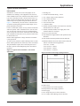
SmartSource™ 2-Stage Horizontal & Vertical
Water Source Heat Pumps
GTH - Horizontal Ceiling
GTV - Vertical Floor
Unit Sizes 026 – 072 • R-410A Refrigerant
Engineered for flexibility and performance™
Catalog 1114-1
Contents
Model Nomenclature.......................................................... 3
AHRI Performance Data..................................................... 5
Introduction......................................................................... 6
SmartSource™ 2-Stage Horizontal & Vertical Water Source
Heat Pumps........................................................................ 6
SmartSource Unique Features........................................... 7
Model GTH-Horizontal & GTV-Vertical Unit............................7
Four Unique Dehumidification Options:..................................8
Hot Gas Reheat Coil..............................................................8
Desuperheater........................................................................8
Loop Pump(s).........................................................................8
Waterside Economizer...........................................................9
Electric Heat (internal or external)..........................................9
Designed-in Sound Reduction................................................9
Cabinet Insulation.................................................................10
Unit Configurations...............................................................10
Field Adjustable ECM Fan Motor.......................................... 11
Two-Stage Compressors - Double Isolated.......................... 11
Water Connections............................................................... 11
Stainless Steel Drain Pan..................................................... 11
Blower Section..................................................................... 11
Disconnect Switch (Option).................................................. 11
Filter & Filter Rack................................................................12
Horizontal Unit Hanger Bracket............................................12
CorMax® Connections.........................................................12
Air-to-Refrigerant Coil...........................................................12
Refrigeration System............................................................12
Unit Control...................................................................... 13
MicroTech III SmartSourcee Unit Control & I/O Expansion
Module..................................................................................13
Built-in Diagnostics...............................................................13
Rotary Fan Speed Selection Switch.....................................13
Operating Modes..................................................................14
Unit Protections & LED Fault Status Annunciation ..............16
MicroTech III SmartSource Unit Controller with LonWorks
Communication Module........................................................18
MicroTech III SmartSource Unit Controller with BACnet
Communication Module........................................................19
Accessories...................................................................... 20
Applications...................................................................... 27
Typical Vertical Installation...................................................27
Typical Horizontal Installation...............................................28
Ductwork and Attenuation....................................................28
Piping...................................................................................30
Water System Quality...........................................................31
Condensate Drain................................................................32
Operating Limits...................................................................32
Unit Selection................................................................... 33
Boiler/Tower (Water Loop) Application:................................33
Geothermal (Ground Loop) Application:...............................33
Loop Pump Application and Selection..................................34
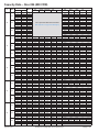
Capacity Data – Size 026 (800 CFM)............................... 36
Capacity Data – Size 032 (1000 CFM)............................. 38
Capacity Data – Size 038 (1250 CFM)............................. 40
Capacity Data – Size 044 (1400 CFM)............................. 42
Capacity Data – Size 049 (1600 CFM)............................. 44
Capacity Data – Size 064 (2000 CFM)............................. 46
Capacity Data – Size 072 (2160 CFM)............................. 48
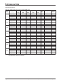
Performance Data............................................................ 50
Fan Performance..................................................................50
Air Flow Correction Factors – Full Load...............................51
Air Flow Correction Factors – Part Load..............................52
Loop Pump Performance.....................................................52
Desuperheater Performance................................................53
Electric Heat Performance...................................................53
Waterside Economizer Cooling Capacity - Vertical Unit.......53
Waterside Economizer Cooling Capacity - Horizontal Unit..54
Electrical Data.................................................................. 55
Correction Factors............................................................ 56
Motorized 2-Way Water Valve..............................................56
Antifreeze.............................................................................56
Physical Data................................................................... 57
Vertical Units........................................................................57
Horizontal Units....................................................................57
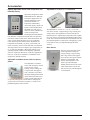
Hoses, Hose Kits and Shutoff Ball Valves for SmartSource
Water Source Heat Pumps...................................................20
Shutoff Ball Valves with Memory Stop..................................20
2 & 3-Way Motorized Water Valves......................................20
Supply and Return Hose Kits...............................................20
Condensate Hose Kits..........................................................22
Electric Duct Heaters (Horizontal Units)...............................22
Filters....................................................................................22
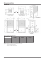
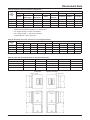
Dimensional Data............................................................. 58
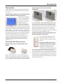
Thermostats..................................................................... 23
Appendix-B....................................................................... 72
Horizontal Unit......................................................................58
Vertical Unit..........................................................................60
Engineering Guide Specifications ................................... 62
Horizontal Unit......................................................................62
Vertical Unit..........................................................................67
Appendix-A....................................................................... 72
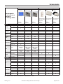
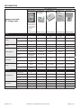
Thermostats and Remote Sensors.......................................23
Thermostats & Remote Sensors used with
GT 2-Stage Units..................................................................25
Sensors used with GT 2-Stage Units...................................26
Page 2 of 76
SmartSource 2-Stage Water Source Heat Pumps
Catalog 1114-1
Model Nomenclature
Note: Text displayed in Bold-Italics designate standard offering.
Category
Code Item
Code Option
Code Designation & Description (Bold-Italic = Standard)
Product Category
1
1
W = Water Source Heat Pump
Model Type
2
2-3
GT = High Efficiency 2-Stage
Configuration 3
4
H =Horizontal
V =Vertical
Nominal Capacity 4
5-7
026 = 26,000 Btuh Nominal Cooling
032 = 32,000 Btuh Nominal Cooling
038 = 38,000 Btuh Nominal Cooling
044 = 44,000 Btuh Nominal Cooling
049 = 49,000 Btuh Nominal Cooling
064 = 64,000 Btuh Nominal Cooling
072 = 72,000 Btuh Nominal Cooling
Unit Control
5
8
B = MicroTech III SmartSource Unit Controller
Design Series (Vintage) 6
9
1
= Revision / Design Series 1
Voltage 7
10
E = 208-230/60/1
F =208-230/60/3
J =265/60/1
K =460/60/3
Range for Entering Water/Glycol Temp.
8
11-12
GW = Ground Water
WL = Water Loop
GL = Ground Loop
Return Air Location
9
13
L
= Left-Hand Return Air & Right-Hand Piping
R = Right-Hand Return Air & Right-Hand Piping
Discharge Air Location 10
14
E = End (Horizontal Unit Only)
T
= Top (Vertical Unit Only)
S = Straight (Horizontal Unit Only)
Fan Motor
11
15
4
= ECM Constant CFM
Dehumidification Option 12
16
B = Hot Gas Reheat Smart Dehumidification
C= Simplified Dehumidification (Lower CFM no HGRH or no Humidistat)
D = Humidistat Controlled Dehumidification (No HGRH)
E = Humidistat Only
Y =None
Sound Package 13
17
Y =None
A =Premium
Coaxial Heat Exchanger Construction
15
19
C = Copper Inner Tube - Steel Outer Tube
(Supply Liquid / Refrigerant)
S = Cupronickel Inner Tube - Steel Outer Tube
Primary Air Coil Option
16
20
S =Standard
E =E-Coated
Communication Module 19
24
B =BACnet
L=
LonWorks
Y =None
Filter Rack 20
25
2
= 4-Sided, 2" w/Duct Collar & Door
3
= 4-Sided, 2" w/Duct Collar, Door, Hi-Merv Seal
4
= 4-Sided, 4" w/Duct Collar, Door, Hi-Merv Seal
Y =None
Filter Type 21
26
A = Disposable
E = Merv 8 Factory-Installed
G = Merv 13 (4-inch thick) Factory-Installed
Y =None
Water Coil - Indoor Air
22
27
E = Waterside Economizer
Y =None
Electric Heating - Indoor Air 23
28
C = 5.0 kW Internal Electric Heater
E = 10.0 kW Internal Electric Heater
F
= 15.0 kW Internal Two Stage Electric Heater
G = 20.0 kW Internal Two Stage Electric Heater
P = Control for Electric Heat, Single 24V Signal (Field-installed Duct Heater by others)
Y =None
Control Secondary Heat Type 24
29
B = Boilerlerss Electric Heat
E = Emergency Electric Heat
P = Primary Electric Heat (No Heat Pump Heating)
S = Supplemental Heat
Y =None
Catalog 1114-1
SmartSource 2-Stage Water Source Heat Pumps
Page 3 of 76
Model Nomenclature
Category
Code Item Code Option
Code Designation & Description (Bold-Italic = Standard)
Desuperheater (Hot Water Generator) 25
30
D =Desuperheater
Y =None
Loop Pump 26
31-32
1S = One Low Head 230 Volt Pump, Grundfos UP26-99F
1L = One High Head 230 Volt Pump, Grundfos UP26-116F
2S = Two Low Head 230 Volt Pumps, Grundfos UP26-99F
2L = Two High Head 230 Volt Pumps, Grundfos UP26-116F
3S = One Low Head 115 Volt Pump, Grundfos UP26-99F
4S = Two Low Head 115 Volt Pumps, Grundfos UP26-99F
YY=None
Coaxial Coil Supply Liquid 27
33
B = 2-Way, Motorized - 24v Valve Control, NO
Flow Control
Y =None
Coaxial Coil Supply Liquid 28
34
A = Auto Flow Control 1.5 GPM
J = Auto Flow Control 9.0 GPM
Auto Flow Reg
B = Auto Flow Control 2.0 GPM
K = Auto Flow Control 10.0 GPM
C = Auto Flow Control 2.5 GPM
L = Auto Flow Control 11.0 GPM
D = Auto Flow Control 3.0GPM
M = Auto Flow Control 12.0 GPM
E = Auto Flow Control 4.0 GPM
N = Auto Flow Control 13.0 GPM
G = Auto Flow Control 5.0 GPM
P = Auto Flow Control 15.0 GPM
H = Auto Flow Control 6.0 GPM
S = Auto Flow Control 18.0 GPM
I
= Auto Flow Control 8.0 GPM
Y=None
Desuperheater Water Flow Options
31
37
Q = Pump - 208-230/60/1 Voltage
Y =None
Water Coil Piping Package Options
35
41
A = 3-Way Motorized - 24V Valve Control, NO to Coax
(Hot Water or Waterside Economizer
Primary Drain Pan Material
39
45
S - Stainless Steel
Compressor Insulation
41
47
B = Compressor Insulation Sound Blanket
Y =None
Compressor Isolation
42
48
B = Isolated base
Insulation - 43
49
A = 1/2" Fiberglass Skin-Faced
Compressor Compartment
B = 1/2" Fiberglass - Foil Faced
C = 3/8" Closed Cell Foam
Insulation - Air Side 44
50
A = 1/2" Fiberglass Skin-Faced
B = 1/2" Fiberglass - Foil-Faced
C = 3/8" Closed Cell Foam
Insulation - Piping
45
51
A = Insulated Piping
Y =None
Cabinet Finish 47
53
A = Powder Coat
Y =None
Cabinet Color
48
54
Y =None
W = Off White
T = Textured Charcoal Bronze
Fan Motor Control 50
56
C = Various Speeds with 4 Adjustment Settings
Disconnect Switch 53
60
Y =None
N =Non-Fused
Control Transformer
55
62
1 = 50VA Control Transformer
2 = 75VA Control Transformer
Thermostat/Sensor Control
56
63
T = Thermostat Control
S = Sensor Control
Expansion Device
75
82
A = Thermal Expansion Valve Thermal Bulb and
Equalizer Tube
Alarm Relay
76
83
A = Alarm Relay (Dry Contacts)
Y =None
Extended Warranty, Parts Only
91
105-106
YY=None
1E = 1-Year, Entire Unit Parts Only
2C = 2-Year Parts (Compressor Only)
2R = 2-Year Parts (Refrigerant Circuit)
3C = 3-Year Parts (Compressor Only)
3R = 3-Year Parts (Refrigerant Circuit)
4C = 4-Year Parts (Compressor Only)
Page 4 of 76
4R = 4-Year Parts (Refrigerant Circuit)
SmartSource 2-Stage Water Source Heat Pumps
Catalog 1114-1
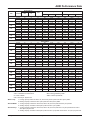
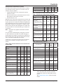
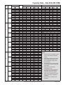
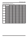
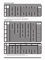
AHRI Performance Data
Rated in accordance with AHRI/ASHRAE/ISO Standard 13256-1.
Unit
Size
Capacity
Modulation
Pressure Drop
PSI
Cooling
GPM
Ft
CFM
Total Cap.
Heating
EER
CFM
Tot Cap.
COP
Water Loop
026
032
038
044
049
064
072
Full load
2.5
5.7
6.5
800
26400
18.0
800
29300
5.7
Part load
2.5
5.7
6.5
700
19800
20.3
700
21800
6.4
Full load
3.3
7.4
7.5
1000
32500
16.5
1000
36400
5.3
Part load
3.3
7.4
7.5
875
24700
18.5
875
27800
6.0
Full load
2.0
4.7
9.0
1250
39000
17.6
1250
44400
5.6
Part load
2.0
4.7
9.0
1090
28300
20.2
1090
32600
6.4
Full load
2.0
4.7
10.5
1400
44400
17.3
1400
50100
5.4
Part load
2.0
4.7
10.5
1225
32900
19.7
1225
36600
6.0
Full load
2.7
6.2
12.2
1600
48900
16.7
1600
55300
5.3
Part load
2.7
6.2
12.2
1400
36900
19.6
1400
40800
6.0
5.2
Full load
4.8
10.9
16.0
2000
64800
17.4
2000
76100
Part load
4.8
10.9
16.0
1750
48200
19.7
1750
53800
5.8
Full load
5.7
12.9
17.5
2160
72700
15.9
2160
88400
5.0
Part load
5.7
12.9
17.5
1920
56400
18.5
1920
64600
5.5
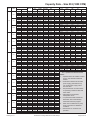
Ground Water
026
032
038
044
049
064
072
Full load
2.5
5.7
6.5
800
29700
26.9
800
23400
5.0
Part load
2.5
5.7
6.5
700
22800
35.3
700
17200
5.1
Full load
3.3
7.4
7.5
1000
35800
24.0
1000
30100
4.8
Part load
3.3
7.4
7.5
875
27600
30.1
875
22500
5.0
Full load
2.0
4.7
9.0
1250
42000
25.4
1250
36200
5.0
Part load
2.0
4.7
9.0
1090
31400
34.2
1090
26000
5.3
Full load
2.0
4.7
10.5
1400
48300
25.4
1400
40600
4.7
Part load
2.0
4.7
10.5
1225
36400
33.6
1225
29000
4.9
4.7
Full load
2.7
6.2
12.2
1600
53800
24.8
1600
45900
Part load
2.7
6.2
12.2
1400
40700
33.5
1400
32900
4.9
Full load
4.8
10.9
16.0
2000
71000
24.7
2000
60600
4.6
Part load
4.8
10.9
16.0
1750
53500
32.8
1750
43200
4.8
Full load
5.7
12.9
17.5
2160
78900
22.6
2160
70900
4.4
Part load
5.7
12.9
17.5
1920
62400
30.8
1920
52300
4.6
Full load
2.5
5.7
6.5
800
27600
20.7
800
18100
4.1
Part load
2.5
5.7
6.5
700
22000
29.8
700
15100
4.6
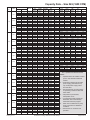
Ground Loop
026
032
038
044
049
064
072
Full load
3.3
7.4
7.5
1000
33800
18.9
1000
23700
4.1
Part load
3.3
7.4
7.5
875
26800
25.9
875
19800
4.5
Full load
2.0
4.7
9.0
1250
40200
20.1
1250
28100
4.2
Part load
2.0
4.7
9.0
1090
30500
28.9
1090
22500
4.7
Full load
2.0
4.7
10.5
1400
45900
19.8
1400
31700
4.0
Part load
2.0
4.7
10.5
1225
35500
28.3
1225
25600
4.4
Full load
2.7
6.2
12.2
1600
50600
19.2
1600
35900
4.0
Part load
2.7
6.2
12.2
1400
39600
28.2
1400
29200
4.4
Full load
4.8
10.9
16.0
2000
67100
19.7
2000
47000
3.9
Part load
4.8
10.9
16.0
1750
52200
28.0
1750
38300
4.3
Full load
5.7
12.9
17.5
2160
75300
18.1
2160
55200
3.7
Part load
5.7
12.9
17.5
1920
60700
26.1
1920
46200
4.2
Legend:Btuh = British Thermal Units per Hour
CFM = Airflow Rate, Cubic Feet per Minute
COP = Coefficient of Performance
EER = Energy Efficiency Ratio
Ft = Feet of Water
GPM = Gallons per Minute
PSI = Pounds per Square Inch
Water Loop:
1. Cooling capacity based on 80.6°F db, 66.2°F wb (27/19°C) EAT and 86°F (30°C) EWT.
2. Heating capacity is based on 68°F (20°C) EAT and 68°F (20°C) EWT.
Ground Water: 1. Cooling capacity is based on 80.6°F db, 66.2°F wb (27/19°C) EAT and 59°F (15°C) EWT.
2. Heating capacity is based on 68°F (20°C) EAT and 50°F (10°C) EWT.
Ground Loop: 1. Cooling capacity is based on 80.6°F db, 66.2°F wb (27/19°C) EAT and 77°F (25°C) EWT at full load or
68°F (20°C) at part load.
2. Heating capacity is based on 68°F (20°C) EAT and 32°F (0°C) EWT at full load or 41°F (5°C) at part load.
Catalog 1114-1
SmartSource 2-Stage Water Source Heat Pumps
Page 5 of 76
Introduction
SmartSource™ 2-Stage Horizontal & Vertical Water Source Heat Pumps
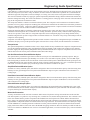
Industry Leading Efficiences, Very Quiet
Operation
SmartSource™ water source heat pumps
from Daikin McQuay combine industryleading efficiencies with low-noise
operation, high indoor air quality and
consistent air temperatures. So now you
can do your part to conserve energy and
enjoy a quiet and comfortable indoor
environment.
Very quiet
SmartSource water source heat pumps are available in both
vertical and horizontal configurations and in sizes from 2 to
6 tons. Part load EERs range from 26.1 to 29.8 for geothermal applications, making these units one of the most efficient available to heat and cool a commercial space. They
are ideal to assist with LEED certification and for earning
energy rebates and tax deductions.
SmartSource water source
heat pumps are exceptionally
quiet, with published sound
ratings as low as 46 dBA.
Sound reduction packages
are available for even greater
attenuation. These units typically operate at low compressor and fan speeds a majority
of the time. The result is even quieter operation, very low
energy consumption and very uniform room air
temperatures.
ECM motors are standard on all units, with field-selectable
CFM settings. ECM motors are more efficient than traditional PSC motors, which is why most utilities offer rebates
for their use. ECM motors also provide near-constant fan
speeds at static pressures up to one inch. The result is
improved air filtration capabilities and more uniform air
distribution.
* Consult your utility provider for rebate opportunities.
Durable construction
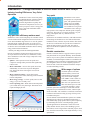
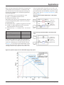
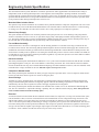
Why part load efficiency matters most
In most environments, heating and cooling systems operate at part load most of the time (see chart below). That’s
where SmartSource units with 2-stage compressors really
shine. Here’s how:
• Quieter – Units operate at lower fan speeds and
compressor settings under part load. That significantly
reduces noise.
• More comfortable – At lower fan speeds, more heat
and humidity is removed as air passes through the
unit. That means the air entering the room is more
comfortable.
• More consistent comfort – At part load, 2-stage
compressors run more often, delivering a more consistent
room air temperature.
• More energy savings – At lower speeds, units use less
energy, so you save on utility costs.
• Lower operating costs – When motors and compressors
cycle on and off less, they last longer. That means fewer
repairs and longer part life.
Sample building load profile, St. Louis, MO
Page 6 of 76
Cabinets on all units feature a rugged, texturized, powdercoat paint finish for exceptional durability. Slotted handles
make it easy to remove panels for maintenance and service.
Cleanable, foil-faced fiberglass insulation is standard in the
air-handling section to minimize sound transmission while
preventing fibers in the air stream. High-IAQ options include 3/8-inch, closed-cell insulation in both the compressor and air-handling sections.
Wide range of options
Available options on all units
include auxiliary electric heat
in both internal (vertical units
only) and external configurations. MERV 8 and 13 filters are
available, with standard 2 inch
filter rack or an optional 4 inch
filter rack that accept a two-inch
or four-inch cartridges. A desuperheater option takes advantage of waste heat from the
compressor to provide domestic hot water, ideal for apartments and condos. Also available is a waterside economizer
to minimize mechanical cooling by using cool loop water
to condition the space.
Several methods of dehumidification options are available,
including hot gas reheat. For geothermal applications, a
unit-mounted loop pump option reduces system complexity
by eliminating the need for a central pumping system.
Typical applications for SmartSource water source heat
pumps include schools, clinics, office buildings, government offices, senior living facilities and other projects, both
new construction and retrofit, where high efficiency is a key
specification.
SmartSource 2-Stage Water Source Heat Pumps
Catalog 1114-1
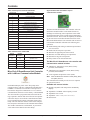
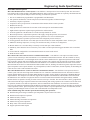
SmartSource Unique Features
Model GTH-Horizontal & GTV-Vertical Unit
Features
1. ECM Fan Motor: 4 field adjustable cfm settings
and 28 programmed cfm values provide a wide range
of airflow selections for quieter operation and lower
energy consumption.
2. Two-Stage Compressor: available in a variety of
commercial voltages, mounted on a double isolation
system for reduced sound and vibration transmission.
3. Refrigerant Circuit: Utilizes R-410A refrigerant with
a bi-flow thermal expansion valve for precise metering
and four way solenoid reversing valve.
4. MicroTech III SmartSource Controls: Easy openprotocol integration with optional LonWorks® or
BACnet®.
5. Unit Status LED: Instant visuals on unit operation for
easy troubleshooting and advanced diagnostics.
6. 4-Sided Filter Rack with Standard 2" or Optional
4" Filters: Designed for easy duct connection and filter
maintenance. MERV 8 & 13 filter options with gasketed
filter seals to meet LEED-NC EQc5 applications with
a leakage rate less than 4 CFM per square foot of filter
area at 0.5"ESP.
7. Stainless Steel Drain Plan: sloped with lipless drain
connection for positive condensate flow to meet
ASHRAE 62.1 Section 5.11.
8. Flush Mounted Fittings: Easy one-wrench connection,
securely fastened to the cabinet corner posts.
9. Blower and Motor Orifice Ring: Easy service without
removing the blower housing or disconnecting the unit
from the duct work.
10.Durable Cabinet Construction: Heavy gauge steel
with powder coated textured paint, lined with cleanable,
foil-faced insulation on the airside.
1
9
6
10
10
7
3
4
8
2
Catalog 1114-1
5
SmartSource 2-Stage Water Source Heat Pumps
Page 7 of 76
SmartSource Unique Features
Four Unique Dehumidification Options:
• Smart Dehumidification – Uses hot gas reheat, humidistat, 2-stage thermostat & smart air flow management for precise
humidity control.
• Simplified Dehumidification – Uses a 3-stage thermostat to optimize unit capacity and fan speed for maximum latent
capacity while decreasing room humidity levels.
• Humidistat Controlled Dehumidification – Uses a humidistat and 2-stage thermostat to control room humidity levels.
• Dehumidification Only – Uses a humidistat in cooling only mode.
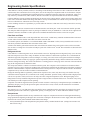
Hot Gas Reheat Coil
For improved indoor climate control, Daikin-McQuay offers
accurate and cost effective dehumidification control using
a hot gas reheat option known as smart dehumidification.
Hot gas reheat with smart dehumidification is an excellent
solution for applications where maintaining low humidity
in a space is crucial. With smart dehumidification, once the
space temperature is satisfied, the humidistat signal diverts
the high temperature refrigerant gas to the reheat coil located downstream of the cooling coil. The conditioned and reheated air prevents over cooling of the space and maximizes
moisture removal for improved indoor comfort. The smart
ECM fan system adjusts the air flow for optimal moisture
removal, and helps keep sound levels at a minimum. It is
especially effective during low load conditions when proper
control is critical. Under humid conditions (60%RH) and
typical loop water temperatures, the latent capacity is optimized for approximately 90% of the sensible capacity. With
loop water conditions of 85°F, the leaving air temperature is
approximately the same as the entering air temperature, resulting
in effective dehumidification without over cooling the space.
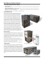
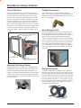
Desuperheater
The factory-installed desuperheater option saves energy by using
heat that would otherwise be “wasted” to the water loop, and uses
it to supplement the heating of domestic water. The desuperheater
has a double-wall, vented coaxial heat exchanger, an optional water pump for 208/230- 1 and 3-phase applications, with controls to
temper the make-up water.
Controls include a refrigerant discharge line thermostat, an
Entering Water Temperature (EWT) thermostat and an “on-off”
switch located on the outside of the unit cabinet to deactivate the
desuperheater system during the heating mode.
This option is available on vertical units sizes 2 tons and larger.
Loop Pump(s)
Not available with Horizontal units
Unit-mounted loop pump(s), available on horizontal and vertical
unit sizes 2 tons and larger, eliminate the need for a central pumping station. Several loop pump options are available to match the
system flow and head requirements for most geothermal and water
loop applications. Sized for approximately 3 GPM/ton, both low
and high head options are available in a single or dual (series flow)
configuration. The series configuration essentially doubles the head
capabilities. These pumps are available for 115 or 230 volt power.
A factory supplied transformer is provided for single-point power
supply.
Insulated cover
Page 8 of 76
SmartSource 2-Stage Water Source Heat Pumps
Catalog 1114-1
SmartSource Unique Features
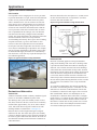
Waterside Economizer
The waterside economizer option helps to reduce energy consumption by
using cool loop water temperatures to condition a space without energizing mechanical cooling. Even in the coldest weather a space can experience a build-up of ambient heat from people, equipment, lighting and
the sun. Buildings with temperature controlled computer rooms, media/
resource rooms or medical equipment rooms, benefit from the waterside
economizer when the geothermal loop field or cooling tower temperatures
are cool enough to provide air conditioning.
Variable flow pumping systems are recommended for these systems to
further reduce energy consumption, while maintaining sufficient water
flow during economizer operation.
The waterside economizer includes a hydronic cooling coil located
upstream of the unit's evaporator coil and after the filter. When entering water temperatures are between 70° to 50°F, a 3-stage thermostat or
room temperature sensor in conjunction with a factory-installed entering water temperature sensor and a 2-position 3-way diverting valve,
determine when loop water can be diverted to the hydronic coil and the
unit coax coil for economizer cooling. Smart fan controls further reduce
energy consumption and sound levels by delivering optimum air flow
during economizer operation. The MicroTech III SmartSource controller
determines if the economizer and mechanical cooling can be activated
together, while optimizing unit airflow. The controller also provides low
temperature protection to avoid economizer operation when entering
water temperatures are below 35°F.
Waterside
Economizer Coil
Waterside
Economizer Coil
Horizontal unit external
duct-mounted electric
heater
Electric Heat (internal or external)
Factory installed electric heaters are available on vertical units. These
heaters are located above the blower housing inside the discharge air plenum. Horizontal units utilize an external duct-mounted electric heater for
field-installation. Unit controls are available for boilerless, supplemental,
primary or emergency electric heat to serve several different application needs. Boilerless electric heat will be energized when the entering
water temperature falls below set point. This will allow electric heat to
function while ensuring the compressor remains off. With supplemental
electric heat control, the wall thermostat will activate the compressor and
heater simultaneously if necessary to maintain room heating conditions.
For primary heat applications, only the electric heater will provide heat
without energizing the compressor. Emergency heat is activated by a 24V
thermostat signal to energize the external duct-mounted electric heat. For
available electric heat sizes and voltages see "Model Nomenclature"
on page 3, "Product Code Index", code item "23".
Vertical unit internal
factory-installed
electric heater
Designed-in Sound Reduction
Provided as standard, the compressor mount has a unique dual-level
vibration isolation system. The compressor is mounted on vibration
isolation grommets to a heavy gauge mounting plate, then isolated
from the cabinet base with rubber grommets to minimize vibration
transfer. The compressor is equipped with thermal overload protection and is located in a well-insulated compartment away from the
air stream to minimize sound transmission. All access panels have
acoustic seals to eliminate panel vibration and minimize radiated
sound levels. Fan noise can be minimized at low airflow with field adjustable ECM fan motor settings. An optional sound reduction kit adds
a 3/4" thick acoustic foam panel of insulation to the fan section and a
compressor blanket (unit sizes 026 to 072 only) to help further reduce
operating sound levels.
Catalog 1114-1
SmartSource 2-Stage Water Source Heat Pumps
Page 9 of 76
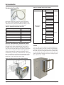
SmartSource Unique Features
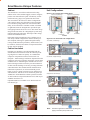
Left-hand, top discharge
Right-hand, top discharge
Control
Box
Water
Connections
Control
Box
Water
Connections
Front
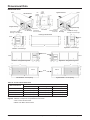
Figure 2: Four horizontal unit configurations
1. Left-hand, end discharge
2. Left-hand, straight discharge
Front
3. Right-hand, end discharge
Front
Premium type insulation is provided standard with all
SmartSource horizontal and vertical unit cabinets providing a high level of indoor air quality. As a standard the
compressor compartment surfaces are lined with 1/2"
fiberglass – multicoated type insulation. Separated from the
compressor section by a partition, the blower section comes
standard with 1/2" thick fiberglass cleanable foil face insulation with edges sealed or tucked to prevent introduction
of fibers into the discharge air stream, providing maximum
sound attenuation. The standard cabinet insulation meets
NFPA 90A requirements, air erosion and mold growth
limits of UL-181, fungal resistance test per ASTM-C1071
and ASTM G21, and meets zero level bacteria growth per
ASTM G22. All insulation has a flame spread of less than
25 and a smoke developed classification of less than 50 per
ASTM E-84 and UL 723.
Optional insulation is available in 3/8" thick closed-cell
non fibrous type.
Figure 1: Two vertical unit configurations
Front
Cabinet Insulation
Unit Configurations
Return Air
The SmartSource vertical floor and horizontal ceiling
cabinet comes with a standard rugged, textured- non-glare,
powder-coat charcoal bronze paint. All cabinetry is fabricated from heavy gauge G-60 galvanized sheet metal.
The vertical floor unit offers two cabinet configurations
with 4 unique cabinet sizes that make up the 2 through 6
ton vertical heat pump product line. For maximum flexibility, each vertical unit is available in either a left‑hand
or right‑hand return air arrangement to provide the optimum piping location and service access. The mirror image
design of the units allow for configuring the system using
minimum ductwork and piping. This helps reduce design,
material and installation costs.
Horizontal ceiling mounted units offer 4 cabinet sizes in
four unique cabinet configurations with the smallest possible footprint, allowing for optimum design flexibility.
Ceiling mounted units ship with heavy metal brackets, rubber isolators, fasteners and washers to suspend and isolate
the unit from the building.
Return Air
Cabinet
4. Right-hand, straight discharge
Front
Note: Unit left or right hand is determined by facing the piping connection (front) side of unit
Page 10 of 76
SmartSource 2-Stage Water Source Heat Pumps
Catalog 1114-1
SmartSource Unique Features
Field Adjustable ECM Fan Motor
ECM motors are standard on all units, with 4 field-selectable CFM settings and 28 programmed CFM values. ECM
motors provide the ultimate in efficiency, performance
flexibility and reduced sound levels. With inherent high
efficiencies compared to conventional PSC or fix speed
motors, the ECM motor can save operating energy. The factory installed rotary fan speed selection switch allows for
easy commissioning through a simple click of the switch
to set the CFM delivered to the space. This allows for field
adjustment of air delivery to the space for sound sensitive
applications or for increased air distribution.
Two-Stage Compressors - Double
Isolated
The two-stage unloading scroll compressor provides excellent part load performance for improved humidity control
and increased efficiency. The compressor has a unique
dual-level vibration isolation system. Mounted on vibration
isolation grommets to a heavy gauge compressor mounting plate, then isolated from the cabinet base with rubber
grommets to minimize vibration transfer. The compressor
is equipped with thermal overload protection and is located
in an insulated compartment away from the air stream to
minimize sound transmission.
Stainless Steel Drain Pan
The vertical unit condensate drain pan is constructed of
corrosion-resistant 304 stainless steel. It is wrapped in
closed-cell insulation, double-sloped with a “lipless”, freedraining pipe connection for positive drainage and an internal trap for improved Indoor Environmental Quality (IEQ)
that meets ASHRAE 62.1-2007 Section 5.11. The drain pan
is provided with solid-state electronic condensate overflow
protection, unlike the less reliable mechanical float switch
used with many competitor drain pans. The horizontal unit
condensate drain pan is sloped, allowing for the unit to
be mounted level in the ceiling, without tilting the unit to
encourage drainage as some competitor units require. It is
constructed of the same high quality materials as the vertical unit drain pan.
Vertical unit drain pan
Horizontal unit drain pan
Blower Section
The blower section includes the ECM motor, a direct-drive
centrifugal fan, fan housing, and drain pan. A duct collar
protrudes through the cabinet to facilitate field-supplied
duct connection. The large size of the blower wheel allows
it to rotate more slowly, reducing motor work to improve
efficiency and provide for quiet operation. A large panel
provides service access to the blower and motor. All
blower/motor assemblies have a removable orifice ring on
the housing to accommodate motor and blower removal
without disconnecting the unit from the ductwork.
Water Connections
The water and condensate connections are FPT fittings,
securely mounted flush to the corner post to allow for
connection to a flexible hose without the use of a back-up
wrench. This helps reduce the time required to connect the
unit and helps prevent delays due to shipping damage. All
vertical units are internally trapped with clear vinyl tubing,
to allow inspection of condensate drain.
Catalog 1114-1
Disconnect Switch (Option)
SmartSource units are available with an optional non-fused
disconnect switch, located on the unit front corner post.
The disconnect switch is used to break power to the unit for
ease of field service and is provided with a lockout/tag out
feature.
SmartSource 2-Stage Water Source Heat Pumps
Page 11 of 76
SmartSource Unique Features
Filter & Filter Rack
CorMax® Connections
Units come standard with a 2" (51mm) thick factory-installed throwaway filter, mounted in a 4-sided combination
filter rack and return air duct collar. Filters can be easily
removed from either side by interchanging the removable
filter door to the right or left side by rotating the filter rack
assembly 180 degrees. A 2" or 4" filter rack is available as
a factory-installed selectable option to accept a Merv 8 or
Merv 13 filter. The high Merv filter rack option is available
with gaskets between it and the cabinet and along the edge
of the tool-less removable door. The gaskets maintain the
leakage rate below 4 CFM per square foot of filter area at
.5" ESP.
Gasketing - keeps the leakage rate
to less than 4 CFM per square foot
of filter area at .5" ESP.
Two CorMax valves are located inside the end access
panel – one on the low side and one on the high side of the
refrigeration circuit – for charging and servicing. All valves
are 7/16" SAE fittings.
Air-to-Refrigerant Coil
The air-to-refrigerant heat exchanger is a large face area
coil with copper tubes and aluminum fins. The fins are
lanced and mechanically bonded to the tubes using finned
edges on the inside which expand during assembly to
enhance heat transfer capabilities. The maximum working
pressure of the heat exchanger is 600 psig (4137 kPa). The
coil is designed for optimal performance in both heating
and cooling while maintaining the benefit of a compact
size. Coils can be provided with an optional E-coating for
extra corrosion protection to meet ASTM B-11 3000 salt
spray test.
Filter Rack Assembly
Easily removed threaded knob
to remove filter access door
Horizontal Unit Hanger Bracket
Each horizontal unit is furnished with a mounting kit that
includes heavy metal hanger brackets for hanging the unit
from field-supplied hanger rods. Rubber isolators are included for sound and vibration attenuation, as are mounting
washers, bolts and lock washers. The hangers are attached
to fasteners at each corner of the unit, which are an integral
part of the cabinet.
Page 12 of 76
Refrigeration System
Units have a coaxial heat exchanger with a copper inner
tube and a steel outer tube. The air coil is a large face area
coil with copper tubes and aluminum fins. Safety controls
include a 600 psi high-pressure switch and low-temperature
sensor to lock out compressor operation at extreme conditions. For additional protection, a 7 psi (48 kPa) low-pressure switch to protect the compressor from low refrigerant
charge. The low setting prevents nuisance trips while
providing additional protection.
SmartSource 2-Stage Water Source Heat Pumps
Catalog 1114-1
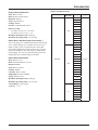
Controls
Unit Control
MicroTech III SmartSourcee Unit Control
& I/O Expansion Module
Built-in Diagnostics
The MicroTech III SmartSource Controller is a microprocessor-based control board in combination with an I/O
Expansion Module for extra functionality. The control box
is accessible through the left or right end corner panel on
horizontal units and through the bottom-front access panel
on the vertical unit. The unit controller is a hard wired interface and in combination with the I/O Expansion Module
provides all the necessary field connections and functionality. All components are easily accessed for service or
replacement.
External LED annunciators are located on the front corner
of the unit chassis to quickly check the operating status of
the unit. The I/O Expansion Module has an independent
LED annunciator to identify operational fault conditions.
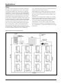
Figure 4: External LED annunciators
MicroTech III
SmartSource
Unit Controller LED's
Figure 3: MicroTech III SmartSource unit control board
and I/O expansion module
I/O Expansion
Module LED's
Rotary Fan Speed Selection Switch
Three control choices are offered with the MicroTech III
SmartSource control system:
■ MicroTech III SmartSource unit controller with I/O
Expansion Module
■ MicroTech III SmartSource unit controller with I/O
expansion module and a LonWorks® communication
module
■ MicroTech III SmartSource unit controller with I/O
expansion module and a BACnet® communication
module
Each option features direct quick-connect wiring to all unitcontrolled components for “clean” wiring inside the control
box. Each control circuit board receives power from a 50
VA or optional 75 VA transformer. The main board can be
wired for 24-volt AC output to the wall thermostat by using
terminals R & C.
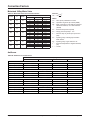
A 4-position rotary switch located in the control box allows
CFM settings to be field adjustable. Fan speed control
optimizes unit fan speed based on thermostat/room sensor
inputs. The rotary switch allows for manually setting an
optimal fan speed specific to the application requirements.
Each position on the rotary switch represents settings 1-4,
see the example for a 2-ton unit in Table 1. For the complete list of fan speed settings see Table 16 on page 50.
Figure 5: 4-position rotary fan speed switch
Table 1: Rotary fan speed settings (2-ton unit example)
CFM Setting
Part Load
Stage 1 Heat
Full Load
Stage 2 Heat
Part Load
Stage 1 Cool
Full Load
Stage 2 Cool
Fan Only
Dehumidification
Electric
Heat
Setting 4 (High)
650
900
650
900
450
600
900
Setting 3 (Standard)
525
800
525
800
400
533
800
Setting 2 (Medium)
470
670
470
670
335
447
800
Setting 1 (Low)
400
525
400
525
263
350
800
Catalog 1114-1
SmartSource 2-Stage Water Source Heat Pumps
Page 13 of 76
Controls
Operating Modes
■ Start-up – The unit will not operate until all the inputs
and safety controls are checked for normal conditions.
■ Cooling Mode – On a call for cooling, the fan will
energize at its “fan only” setting, the pump request will
engergize, the 45 second flow timer will start after the
flow, compressor minimum off, and random startup
timers are expired, the compressor and fan will start at
the stage 1 cooling settings. If room setpoint conditions
are not satisfied, the fan will operate at the stage 2
cooling settings. When the room setpoint conditions are
satisfied, the compressor will shut off and the fan will
operate according to its “fan only” setting when enabled
for continuous fan operation. If fan cycling is enabled,
the fan will turn off once room setpoint conditions are
satisfied.
■ Dehumidification Modes – There are four
dehumidification modes of operation;
1. Smart Dehumidification with Hot Gas Reheat
2. Simplified Dehumidification
3. Humidistat Controlled Dehumidification
4. Dehumidification Only
▪ Smart Dehumidification – Uses hot gas reheat,
a humidistat, a 2-stage thermostat and air flow
management for precise humidity control. When the
cooling and heating temperature setpoint is satisfied
and there is a call for dehumidification, maximum
dehumidification is initiated by energizing the
fan at its “fan only” setting, energizing the pump
request, engergizing the 45 second proof-of-flow
timer, energizing the hot gas reheat solenoid valve,
energizing the compressor at maximum cooling, and
energizing the fan at the dehumidification setting.
When the room humidity conditions are satisfied,
the compressor will shut off and the fan will operate
according to its “fan only” setting when enabled for
continuous fan operation. If fan cycling is enabled,
the fan will turn off, once room humidity conditions
are satisfied.
▪ Simplified Dehumidification – Uses a 3-stage
thermostat and air flow management to optimize
unit capacity and fan speed for maximum latent
capacity while decreasing room humidity levels.
On a call for cooling, the fan will energize at its
“fan only” setting, the pump request will energize,
the 45 second flow timer will start, after the flow,
compressor minimum off, and random startup
timers are expired, the compressor will start at
stage 1 cooling and the fan will energize at its
dehumidification setting. If the room setpoint
temperature is still not satisfied, the fan will be
energized at the stage 1 cooling settings. If the
room setpoint temperature is still not satisfied,
the compressor and fan will operate at the stage
2 cooling settings. When the room temperature
Page 14 of 76
conditions are satisfied, the compressor will shut off
and the fan will operate according to its “fan only”
setting when enabled for continuous fan operation.
If fan cycling is enabled, the fan will turn off, once
room setpoint conditions are satisfied.
▪ Humidistat Controlled Dehumidification – Uses
a humidistat and 2-stage thermostat to control room
humidity levels. On a call for dehumidification, the
fan will energize at its “fan only” setting, the pump
request will energize, the 45 second flow timer will
start, after the flow, compressor minimum off, and
random startup timers are expired, the compressor
will start at stage 1 cooling and the fan will energize
at its dehumidification setting. If the room setpoint
temperature is not satisfied, the fan will be energized
at the stage 1 cooling settings. If the room setpoint
temperature is still not satisfied, the compressor
and fan will operate at the stage 2 cooling settings.
When the room temperature and humidity
conditions are satisfied, the compressor will shut off
and the fan will operate according to its “fan only”
setting when enabled for continuous fan operation.
If fan cycling is enabled, the fan will turn off once
room setpoint conditions are satisfied.
▪ Dehumidification Only – Uses a humidistat in the
cooling only mode. On a call for dehumidification,
the fan will energize at its “fan only” setting, the
pump request will energize, the 45 second flow
timer will start, after the flow, compressor minimum
off, and random startup timers are expired, the
compressor will start at stage 1 cooling and the
fan will energize at its dehumidification setting.
Room temperature conditions are not monitored
or maintained. The unit only responds to a call
for dehumidification. When the room humidity
conditions are satisfied, the compressor will shut off
and the fan will operate according to its “fan only”
setting when enabled for continuous fan operation.
If fan cycling is enabled, the fan will turn off once
room setpoint conditions are satisfied.
■ Heating Mode – On a call for heating, the fan will
energize at its "fan only" setting, the pump request
will energize, the 45 second flow timer will start,
after the flow, compressor minimum off, and
random startup timers are expired, the compressor
and fan will start at stage 1 heating settings; the
reversing valve shall energize 5 seconds after the
compressor turns on. If room setpoint conditions are
not satisfied, the fan will operate at stage 2 heating
settings. When the room setpoint conditions are
satisfied, the compressor will shut off and the fan
will operate according to its “fan only” setting when
enabled for continuous fan operation. If fan cycling
is enabled, the fan will turn off, once room setpoint
conditions are satisfied.
SmartSource 2-Stage Water Source Heat Pumps
Catalog 1114-1
Controls
■ Boilerless Electric Heat Mode – When the entering
water temperature is below setpoint, the compressor
will not be allowed to operate. On a call for heating,
stage 1 electric heat will be energized and the
fan will start at its electric heat setting. For units
equipped with 2 stages of electric heat, if room
setpoint conditions are not satisfied, the second
stage of electric heat will be energized and the fan
will continue to operate at its electric heat setting.
When the room setpoint conditions are satisfied,
electric heat will be de-energized and the fan will
continue to operate at its “fan only” setting when
enabled, for continuous fan operation. If fan cycling
is enabled, the fan will turn off after 45 seconds
once room setpoint conditions are satisfied.
■ Supplemental Electric Heat Mode – On a call for
heating, the fan will energize at its “fan only”
setting, the pump request will energize, the
45 second flow timer will start. After the flow,
compressor minimum off, and random startup
timers are expired, the compressor and fan will
start at stage 1 heating settings; the reversing valve
shall energize 5 seconds after the compressor turns
on. If room setpoint conditions are not satisfied,
the fan will operate at stage 2 heating settings.
If room setpoint conditions are still not satisfied,
the compressor will continue to operate and stage
1 electric heat will be energized and the fan will
operate at its electric heat setting. For units equipped
with 2 stages of electric heat, if room setpoint
conditions are still not satisfied, the second stage
of electric heat will be energized and the fan will
continue to operate at its electric heat setting. When
the room setpoint conditions are satisfied, electric
heat will be de-energized allowing the compressor
to remain on if necessary to maintain room setpoint
conditions. The fan will operate according to its
“fan only” setting when enabled, for continuous fan
operation. If fan cycling is enabled, the fan will turn
off once room setpoint conditions are satisfied.
■ Primary Electric Heat Mode – On a call for heating,
stage 1 electric heat will be energized and the
fan will start at its electric heat setting. For units
equipped with 2 stages of electric heat, if room
setpoint conditions are not satisfied, the second
stage of electric heat will be energized and the fan
will continue to operate at its electric heat setting.
When the room setpoint conditions are satisfied,
electric heat will be de-energized and the fan will
continue to operate at its “fan only” setting when
enabled, for continuous fan operation. If fan cycling
is enabled, the fan will turn off after 45 seconds
once room setpoint conditions are satisfied.
Catalog 1114-1
■ Emergency Electric Heat Mode – A 24v control signal
from the thermostat will initiate a call for stage 1 or
stage 2 electric heat. The compressor will not operate
and the fan will start at its electric heat setting.
■ Occupied Mode – The MicroTech III SmartSource
unit controller will manage occupied and unoccupied
modes of operation. The occupancy mode can be
established by a BACnet or LonWorks communication
signal, from a room sensor equipped with “Occupied/
Unoccupied” mode functions, or a thermostat equipped
with an “Occupied/Unoccupied” mode switch. When
in the occupied mode, the unit will be controlled to
its occupied setpoint conditions. The occupancy state
will be displayed on sensors equipped with “Occupied/
Unoccupied” mode functions and annunciation
capabilities.
■ Unoccupied Mode – When operating in the unoccupied
mode, the unit will be controlled to its unoccupied
setpoint conditions and the fan will cycle according to a
call for cooling, dehumidification or heating. A simple
“grounded” signal between terminals U and C on the
MicroTech III SmartSource unit controller will place
the unit into the unoccupied mode for night setback
operation. The occupancy state will be displayed on
sensors equipped with “Occupied/Unoccupied” mode
functions and annunciation capabilities.
■ Override Mode – A momentary (4 to 9 seconds) press
of the “Override” button on the thermostat or room
sensor during the unoccupied mode will cause the
unit to operate in the occupied mode for two hours,
for after-hours heating, cooling or dehumidification.
“OVERRIDE” will be displayed on sensors equipped
with override button and annunciation capabilities.
■ “Energy Save” Bypass Mode – BACnet or LonWorks
units can receive a signal from the Building Automation
System (BAS) to initiate the energy savings mode. This
mode is typically initiated by the BAS with smart grid
technologies to save energy. The savings is driven by
reducing peak electrical demand for the building. Once
initiated, the MicroTech III SmartSource unit controller
will reset its effective setpoint to minimize the stage
of compressor operation. “E-SAVE” will be displayed
on sensors equipped with bypass mode annunciation
capabilities.
■ Motorized Water Valve or Pump Start – When there
is a call for cooling, dehumidification or heating, the
MicroTech III SmartSource unit controller will energize
its IV/PR (H8) terminal to open the motorized water
valve or start the loop pump 45 seconds prior to starting
the compressor. The IV/ PR (H8) terminal may be
“daisy chained” between 200 units.
SmartSource 2-Stage Water Source Heat Pumps
Page 15 of 76
Controls
Unit Protections & LED Fault Status
Annunciation
Refrigerant Circuit High Pressure Protection
A normally closed high (compressor discharge) pressure
switch is used in SmartSource units to help protect the
refrigerant circuit from excessively high pressure. The
controller will monitor this switch.
Note: Due to the method of sensing the HP switch,
the true state cannot be determined unless the
compressor output is active.
Refrigerant Circuit Low Pressure Protection
A normally closed low (compressor suction) refrigerant
pressure switch is used in SmartSource units to help protect
the refrigerant circuit from excessively low refrigerant
pressure. The controller will monitor the switch, when the
low-pressure switch contacts are open for more than the
low-pressure time delay, default is 30 seconds, the controller will go into the low-pressure fault mode.
Condensate Overflow Sensor (Cooling & Dehumidification Modes Only)
The controller is designed to sense when condensate water
levels in the drain pan become excessively high. When high
condensate water levels are detected during cooling or dehumidification mode, the controller will go into condensate
overflow warning mode.
• No condensate overflow warnings will occur when the
unit is running in heating modes, thus allowing the unit
to heat with high condensate water levels.
• The fan and pump will operate normally during the
condensate overflow fault mode.
Heat Exchanger Low Temperature Protection
The Suction Line Temperature sensor is located on the suction line of the compressor and is used to help protect the
unit from excessively low water coil and air coil temperatures.
• The control module will monitor the SLT sensor and
if the refrigerant temperature drops below the low
temperature limit set point, the controller will go into
the low temperature fault mode.
The controller is programmed for different responses if a
low temperature fault is detected during heating or cooling
modes.
■ Low Refrigerant Temperature Protection in heating
mode
■ Low Refrigerant Temperature Protection in cooling
mode
Low Water Temperature Protection
There are two versions of low water temperature protection,
1. Low Entering Water Temperature protection or;
2. Low Leaving Water Temperature protection.
Page 16 of 76
Emergency Shutdown
The controller will be in remote shutdown when the
emergency shutdown contact closes to ground. Remote
shutdown is provided so that when properly connected to
a water loop controller or remote switch, the emergency
shutdown input can be used to shut down the water source
heat pump.
Low Voltage (Brownout) Protection
The Baseboard controller module will monitor the 24 volt
power input supplied to the board. If a low voltage condition is detected the control module will shut down the unit
to protect electrical components from low line voltage
conditions.
■ Electrical Characteristics
• Line voltage feeds the primary side of the 24 volt
transformer whose secondary output supplies power
to the controls.
• When the line voltage drops, the transformer output
voltage drops a corresponding amount.
• The Baseboard control module monitors the supply
voltage from the transformer and after calibration
will detect low line voltage conditions
■ Low Voltage Calibration Process
• The Low Voltage Calibration process is first
performed at the factory, and results in a Brownout
Reference set point that will protect the unit under
normal operating conditions in the field.
Note: The Brownout Reference set point may have to be
recalibrated when the unit is installed if the supply
voltage in the building is low.
■ Low Voltage Protection Control Sequence
• When the line voltage drops below 80% of the unit
nameplate rated value, the controller senses the
lower 24 volt supply voltage.
Intelligent Alarm Reset
This feature applies to faults that do not clear automatically.
It is used to minimize nuisance trips of automatic lockouts
caused by temporary conditions that might inhibit the unit
from performing normal functions.
• When an Intelligent Reset alarm occurs, it is counted
and the alarm is cleared when the condition returns to
normal. If the alarm occurs two more (for a total of 3)
times within a 24-hour period, the heat pump remains
off (locked out) until the alarm is manually cleared.
The control board is reset by a short interruption of unit
power, or remotely reset by pressing the timed override
button for more than 10 seconds, or through the service
tool, or over the network.
• At the end of the 24 hour period, all counts for
Intelligent Reset alarms are reset to zero.
SmartSource 2-Stage Water Source Heat Pumps
Catalog 1114-1
Controls
Remote Reset of Automatic Lockouts
The Remote Reset feature provides the means to remotely
reset automatic lockouts. There are (3) means to reset an
automatic lockout condition:
• Using the thermostat create 2 demands for capacity
within 30 seconds.
• Press the Room Sensor or Thermostat Timed Override/
Reset Button for more than 10 seconds
• Turn the unit power off
When the cause of the fault condition has been cleared, and
the unit transitions from not requiring any capacity to needing any capacity twice within 30 seconds (accomplished by
user manipulation of the Heat/Cool/Auto/Off switch on the
thermostat), an alarm reset equivalent to a tenant override
button reset is generated. The intelligent reset counter and
the 24 hour timer are cleared when this type of alarm reset
is generated.
Note: This feature only applies to thermostat controlled
systems.
For room sensor controlled units, pressing the “Override”
or “Reset” button for more than 10 seconds will apply a
ground signal to the tenant override in(screw terminal connection at TB1 pin 4) will clear the lockout alarm once the
cause of the fault condition has been cleared.
A unit power cycle can also be used to clear an automatic
lockout if the conditions causing the fault have been
cleared.
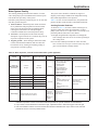
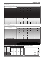
Table 2: MicroTech III SmartSource unit controller fault
& status LED's
Service Test Mode Enabled
Mode
Flash
Flash
Flash
Unoccupied Mode
Mode
ON
ON
OFF
Occupied, Bypass, Standby,
or Tenant Override Modes
Mode
OFF
ON
OFF
Note: Mode/faults are listed in order of priority.
Table 3: I/O expansion module fault & status LED's
Description
Type
Yellow
Green
Red
Baseboard Communication Fail
Fault
Flash
OFF
Flash
Entering Water Temp
Sensor Fail
(Boilerless Electric Heat
or Waterside Economizer
Only)
Fault
ON
OFF
Flash
Low Entering Water
Temperature
(No Display On Boilerless
Electric Heat)
Fault
OFF
ON
Flash
Fan is OFF
Mode
OFF
ON
OFF
Fan Running at Low
Speed (0 to 33%) Duty
Cycle
Mode
OFF
Flash
OFF
Fan Running at Medium
Speed (34 to 66%) Duty
Cycle
Mode
ON
Flash
OFF
Fan Running at High
Speed (67 to 100%) Duty
Cycle
Mode
Flash
Flash
OFF
Table 4: Fault recovery and reset
Fault Description
Auto
Recovery
Tenant
Override
Button
Reset
Network
Reset
Yes
No
No
Type
Yellow
Green
Red
IO Expansion Communication Fail
Fault
ON
Flash
Flash
I/O Expansion
Communication Fail
Invalid Configuration
Fault
Flash
Flash
OFF
Invalid Configuration
No
No
No
Low Voltage Brownout
Fault
OFF
Flash
OFF
Low Voltage Brownout
Yes
No
Yes
Emergency Shutdown
Mode
OFF
Flash
OFF
All Sensor Failures
No
No
Yes
Compressor High Pressure
Fault
OFF
OFF
Flash
Compressor High Pressure
No
Yes
Yes
Compressor Low Pressure
Fault
OFF
OFF
ON
Compressor Low Pressure
Yes1
Yes
Yes
Compressor Low Suction Temp or
Freeze Fault Detect (In Heating
Mode)
Yes1
Yes
Yes
Compressor Low Suction Temp or
Freeze Fault Detect (In Cooling or
Dehumidification Modes)
No
Yes
Yes
Condensate Overflow
Yes
No
Yes
Low Entering Water Temp
Yes
No
No
ON
Serial EEPROM Corrupted
No
No
No
Waterside Economizer Low Temp
Cutout
Yes
No
No
Description
Compressor Suction Temp
Sensor Fail
Fault
Flash
Flash
ON
Compressor Low Suction
Temp
Fault
Flash
OFF
OFF
Freeze Fault Detect
Fault
Flash
OFF
Flash
Room Temp Sensor Fail
(Room Sensor Control Only)
Fault
Flash
Flash
ON
Leaving Water Temp Sensor
Fail
Fault
Flash
Flash
Condensate Overflow
Fault
ON
OFF
OFF
Serial EEPROM Corrupted
Fault
ON
ON
ON
Waterside Economizer Low
Temp Cutout (WSE Control &
Call for Cooling Only)
Mode
Flash
ON
Flash
Catalog 1114-1
Note: 1 Indicates auto recover is subject to intelligent
alarm reset. Alarm auto recovers on first two
occurrences, locked out on third within 24 hour
period.
See "Intelligent Alarm Reset" section for further
details.
SmartSource 2-Stage Water Source Heat Pumps
Page 17 of 76
Controls
Table 5: Priority Level of Faults and Modes
Priority Level
Mode or Fault
1
I/O Expansion Communication Fail
2
Invalid Configuration
3
Low Voltage Brownout
4
Emergency Shutdown Mode
5
Compressor High Pressure
6
Compressor Low Pressure
7
Compressor Suction Temp Sensor Fail
8
Compressor Low Suction Temp
9
Freeze Fault
10
Room Temp Sensor Fail
11
Entering Water Temp Sensor Fail
12
Leaving Water Temp Sensor Fail
13
Condensate Overflow
14
Low Entering Water Temp
15
Serial EEPROM Corrupted
16
Waterside Economizer Low Temp Cutout
17
Service Test Mode
Table 6: Room sensor status LED
LED ON
Time (Sec.)
LED OFF
Time (Sec.)
Operating Mode
0.5
0.5
Alarm Condition or Network “Wink”
Operation Active
0.0
Continually
Tenant Override Is Active
0.5
5.5
Unoccupied Mode
5.5
0.5
Standby Mode
Continually
0.0
Occupied or Bypass Modes
MicroTech III SmartSource Unit Controller
with LonWorks Communication Module
Figure 6: MicroTech III LonWorks snap-in
communication module
The MicroTech III SmartSource unit controller with communication module includes a unit-mounted return air,
discharge air and leaving water temperature sensor. Wall
mounted temperature sensors include setpoint adjustment
and tenant override. The user has the capability of substituting the wall sensor with a duct-mounted return air sensor.
MicroTech III SmartSource unit controller with LonWorks
Communication Module orchestrates the following unit
operations:
■ Enable heating and cooling to maintain setpoint based
on a room sensor
■ Enable fan and compressor operation
■ Monitors all equipment protection controls
■ Monitors room and discharge air temperatures
■ Monitors leaving water temperature
■ Relays status of all vital unit functions
The MicroTech III SmartSource unit controller with
communication module includes:
■ A Return Air Temperature sensor (RAT) (factory
provided, field-installed)
■ A Discharge Air Temperature sensor (DAT) (factory
provided, field-installed)
■ A Leaving Water Temperature sensor (LWT)
Note: Refer to IM 956-X for details to install (RAT), (DAT)
and (LWT) sensors.
The communication module provides access to setpoints
for operational control
Each Daikin McQuay water source heat pump can be
equipped with a LonWorks communication module that is
LonMark 3.4 certified. The controller is microprocessorbased and is designed to communicate over a LonWorks
communications network. It can be factory or field-installed.
The unit controller is programmed and tested with all the
logic required to monitor and control the unit. An optional
wall sensor may be used with the communication module
to provide limited local control of the Water Source Heat
Pump. The unit controller monitors water and air temperatures and passes information to the communication module.
The module communicates with the BAS, to provide network control of the Water Source Heat Pump.
Page 18 of 76
Available wall sensors include:
■ Digitally Adjustable with Temperature & Humidity
Display
■ Adjustable Cool/Warm with Occupancy Switch
■ Adjustable 55°F to 95°F
■ Adjustable -3°F to +3°F (-1.5°C to +1.5°C)
■ Basic Sensor
SmartSource 2-Stage Water Source Heat Pumps
Catalog 1114-1
Controls
MicroTech III SmartSource Unit Controller
with BACnet Communication Module
Daikin McQuay water source heat pumps are available with
a BACnet MS/TP communication module that is designed
to communicate over a BACnet MS/TP communications
network to a building automation system (BAS). It can be
factory or field-installed.
The unit controller is programmed and tested with all the
logic required to monitor and control the unit. An optional
wall sensor may be used with the communication module to
provide limited local control of the water source heat pump.
The unit controller monitors water and air temperatures
and passes information to the communication module. The
module communicates with the BAS, to provide network
control of the water source heat pump.
The module makes operational data and commands available on a communications network using BACnet objects
and properties:
■ The network cable is a shielded twisted-pair cable
■ Network communications run up to 76.8 Kbps
■ DIP switches on the controller enable the MS/TP MAC
address to be set in the range 0-127
■ Four green status LEDs on the communication module
indicate communication activity on the MS/TP
communication network and with the unit controller
The MicroTech III SmartSource unit controller with
communication module includes:
■ A Return Air Temperature sensor (RAT) (factory
provided, field-installed)
■ A Discharge Air Temperature sensor (DAT) (factory
provided, field-installed)
■ A Leaving Water Temperature sensor (LWT)
Note: Refer to IM 956-X for details to install (RAT), (DAT)
and (LWT) sensors.
The communication module provides access to setpoints for
operational control.
Available wall sensors include:
■ Digitally Adjustable with Temperature & Humidity
Display
■ Adjustable Cool/Warm with Occupancy Switch
■ Adjustable 55°F to 95°F
■ Adjustable -3°F to +3°F (-1.5°C to +1.5°C)
■ Basic Sensor
Figure 7: MicroTech III BACnet snap-in communication
module
MicroTech III SmartSource unit controller with BACnet
MS/TP Communication Module orchestrates the following
unit operations:
■ Enable heating and cooling to maintain setpoint based
on a room sensor
■ Enable fan and compressor operation
■ Monitors all equipment protection controls
■ Monitors room and discharge air temperatures
■ Monitors leaving water temperature
■ Relays status of all vital unit functions
Catalog 1114-1
SmartSource 2-Stage Water Source Heat Pumps
Page 19 of 76
Accessories
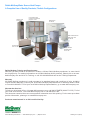
Hoses, Hose Kits and Shutoff Ball Valves
for SmartSource Water Source Heat
Pumps
Daikin McQuay sells a variety of flexible supply, return and
condensate hoses and hose assemblies for connecting its
water source heat pumps to a building's hard piping system.
Both standard and fire-rated hoses are available.
Figure 8: Flexible, steel braided supply and return
hoses
Supply and return hoses have a swivel fitting at one end to
facilitate removal of the unit for replacement or service.
Standard supply and return fire-rated hoses have either
a thermoplastic rubber or synthetic polymer core with a
braided covering of stainless steel. Fittings are either plated
steel or brass.
2 & 3-Way Motorized Water Valves
2-way valves are used for variable pumping applications
when more than one unit is installed on a common loop.
These valves are also used to conserve water when used for
ground water applications.
3-way valves are used for constant flow applications or
installed at the end of a variable flow branch piping run to
maintain minimum flow conditions.
Figure 10: 2-way and 3-way motorized water valves
Table 8: Available motorized valves
Type
2-Way
Motorized
Table 7: Available fire rated supply and return hoses
Description
Connection
Size (O.D.)
1/2"
Supply and
Return Hoses
3/4"
1"
Length
24"
36"
Size
Connection
1/2"
Sweat
3/4"
Sweat
1"
Sweat
1/2"
NPT
3/4"
NPT
1"
NPT
Waterside Economizer Valves
3-Way
Motorized
24"
1/2"
Sweat
3/4"
Sweat
1"
Sweat
36"
24"
Supply and Return Hose Kits
36"
Figure 11: Supply and return hoses
Shutoff Ball Valves with Memory Stop
Constructed of brass and rated at 400 psig (2758 kPa)
maximum working pressure. Valves have a built-in adjustable memory stop to eliminate rebalancing. Valves have
FPT connections on both ends for connection to the water
hose and to the field piping.
Figure 9: Shutoff ball valve with memory stop
Supply Hose - Combination Ball Valve & Strainer
The supply valve body is a combination Y-strainer full port
shut-off valve and union for use in HVAC systems. Strainers are furnished with a 20 mesh stainless steel screen,
hose end drain (blow down) valve for purging, one pressure/temperature port for commissioning, and one plugged
bypass port. Three additional 1/4ʺ taps are plugged and
available for accessories when specified. A variety of pipe
connections are available on both the fixed and union ends.
Standard end connections are female pipe thread.
Page 20 of 76
SmartSource 2-Stage Water Source Heat Pumps
Catalog 1114-1
Accessories
Supply Hose Construction
Body: Brass C37000
Ball: Full Port Chrome Plated
Ball Stem: Teflon®
Stem: Explosion Proof
O-Rings: EPDM
Strainer: 20 Mesh Stainless Steel
Bypass Port Tap:
• 1/2" NPTF for sizes 1/2", 3/4" and 1"
• 3/4" NPTF for sizes 1-1/4", 1-1/2"
Maximum Working Pressure: 400 psig
Maximum Operating Temp: -4°F to 250°F
Table 9: Available hose kits
Description
Connection
Size (O.D.)
Length
0.5
1.0
1.5
2.0
2.5
1/2"
3.0
3.5
4.0
4.5
5.0
Return Hose - Ball Valve with Circuit Sentry™
The Circuit Sentry is a combination automatic flow limiting
valve, commissioning valve, and shut-off valve for use in
HVAC systems. Valves are furnished with a removable
flow limiting diaphragm cartridge to allow easy access for
inspection, cleaning, or flow rate changes without disturbing the piping. Two 1/4" pressure/temperature ports and a
hanging ID tag for commissioning are standard.
Return Hose Construction
Body: Brass C37710
Ball: Chrome Plated Brass C37710
Ball Seal: EPDM
Stem: Blow-Out Proof
O-Rings: EPDM
Cartridge: Brass C36000
Diaphragm: Reinforced EPDM
Spring: Stainless Steel
Maximum Working Pressure: 400 psig
Maximum Operating Temp: -4°F to 250°F
Control Range: 2 psi to 60 psi
Accuracy: +/- 5%
GPM
5.5
6.0
3.0
3.5
4.0
4.5
5.0
5.5
Hose Kit
6.0
24" & 36"
6.5
3/4"
7.0
7.5
8.0
9.0
10.0
11.0
12.0
13.0
15.0
8.0
9.0
10.0
1"
11.0
12.0
13.0
15.0
18.0
Catalog 1114-1
SmartSource 2-Stage Water Source Heat Pumps
Page 21 of 76
Accessories
Condensate Hose Kits
Table 11: Available electric duct heaters
Description
kW
Voltage/Hz/Phase
Unit Size
208-240/60/1
5
208-240/60/3
277/60/1
480/60/3
208-240/60/1
10
Horizontal ceiling units require an external condensate
hose. These can be ordered as the long clear plastic type
with the necessary clamps and a MPT hose fittings, or fire
rated type for connection to the FPT field piping.
Table 10: Available condensate hose kits
Description
Size & Nominal Length
Hose, Fire Rated Condensate
1" FPT x 24"
Hose, Fire Rated Condensate
1" FPT x 36"
Hose, Fire Rated Condensate
3/4" FPT x 24"
208-240/60/3
277/60/1
480/60/3
208-240/60/1
Electric Duct
Heater Kit
5
208-240/60/3
277/60/1
480/60/3
208-240/60/1
10
208-240/60/3
277/60/1
480/60/3
036-072
208-230/60/1
Hose, Fire Rated Condensate
3/4" FPT x 36"
Hose, Plastic Condensate w/Fittings
3/4" x 30"
Hose, Plastic Condensate w/Fittings
3/4" x 36"
460/60/3
Hose, Plastic Condensate
1" x 30"
208-230/60/1
Hose, Plastic Condensate
1-1/4" x 38"
15
20
208-230/60/3
208-230/60/3
460/60/3
Electric Duct Heaters (Horizontal Units)
Horizontal units utilize a (field-installed) external ductmounted electric heater. With boilerless electric heat, if
the EWT is above the set point of the EWT thermostat, a
switch is located in the control box to activate electric heat
in the event of a compressor failure. With supplemental
electric heat control the compressor and heater operate
simultaneously, activated by a wall thermostat. “Emergency
heat” is activated by a 24V signal for external duct-mounted electric heat. This function is activated from the wall
thermostat via the “Emergency Heat” switch.
024-032
Filters
A 2" or 4" filter rack is available as a field-installed accessory to accept a Merv 8 or Merv 13 filter, for applications
requiring optimal Indoor Air Quality (IAQ). The high Merv
filter rack is provided with gaskets between it and the cabinet and along the edge of the tool-less removable door. The
gaskets maintain the leakage rate below 4 CFM per square
foot of filter area at .5" ESP.
Figure 12: External electric heater (field-installed)
Page 22 of 76
SmartSource 2-Stage Water Source Heat Pumps
Catalog 1114-1
Accessories
Thermostats
Daikin-McQuay has a line of thermostats and thermostat
accessories to serve the SmartSource line of water source
heat pumps.
Programmable and Non-Programmable
Thermostats
Programmable Touch Screen for Smart Dehumidification or Waterside Economizer Control
With advanced capabilities
to control Smart Dehumidification or the Waterside
Economizer, the Programmable Touch Screen
thermostat offers precise
temperature and humidity
sensing and control. When
combined with a multiple-stage heat pump and electric heat
control this thermostat provides the ultimate in thermostatic
control with a +/- 1°F accuracy. It’s large, 12-square-inch
blue backlight display is easy to see and easy to program in
low light conditions. Enhanced Smart Dehumidification fan
speed control combined with 2-stage compressor control
allows for maximum dehumidification capability. An
exclusive Cool Saving feature saves energy during peak
cooling demand periods. Remote indoor or outdoor
temperature sensing is also available with the accessory
remote sensors.
Thermostats and Remote Sensors
Remote Sensors for the Programmable Touch
Screen
Outdoor Sensor
Indoor Sensor
Remote indoor temperature sensor provides the ability to
measure room temperature remote from the thermostat location. The remote outdoor temperature sensor provides the
ability to display the outdoor temperature at the thermostat.
Catalog 1114-1
ProgrammableNon-Programmable
For 2-stage heating, 2-stage cooling and boilerless electric
heat control, both the Programmable and Non-Programmable thermostats provide simple control capabilities. With
alarm fault clearing, a timed override button and unit status
LED, these thermostats provide an easy interface to the
MicroTech III SmartSource controller for both automatic
and manual changeover capabilities. Each can be connected
to the accessory remote temperature sensor.
Remote Room Sensor for the Programmable and
Non-Programmable Thermostats
The remote indoor temperature sensor
provides the ability to measure room
temperature remote from the thermostat
location.
MicroTech III Water Source Heat
Pump Room Temperature Sensors
A MicroTech III Water Source Heat
Pump Room Temperature Sensor is
required when connecting a SmartSource
unit to a Building Automation System (BAS) using either
the LonWorks or BACnet Communication Module. All
MicroTech III Water Source Heat Pump Room Temperature
Sensors provide electronic sensing of the room temperature
for multiple-stage cooling and heating control, electric heat
control, unit status annunciation, timed tenant override, and
fault clearing capabilities.
SmartSource 2-Stage Water Source Heat Pumps
Page 23 of 76
Accessories
Digitally Adjustable Sensor with Temperature and
Humidity Display
Specifically designed for Smart
Dehumidification or Waterside
Economizer applications, the
Digitally Adjustable sensor
provides the ultimate of
temperature and humidity
control and display, simple user
interface, alarm annunciation,
and alarm reset. The easy to
read LCD clearly identifies the
system operating mode
including Smart Dehumidification (Dehum), occupied/unoccupied mode, fan operation,
unit status, timed override status, alarm annunciation, and
energy savings mode through a series of recognizable
icons. Tactile response buttons initiate adjustments for
temperature and humidity set points, system mode, fan
mode, occupancy, tenant override and fault reset functions.
The large numeric LCD will display space temperature (°F
or °C) and space humidity (%RH) along with the corresponding setpoint conditions. The Digitally Adjustable
Sensor is required for BACnet or LonWorks applications.
However, it can also be installed as a standalone sensor
using factory default set points.
Adjustable 55° to 95°F or +/- 3°F Sensors
Adjustable 55º to 95ºF
The adjustable 55° to 95°F or +/- 3°F or +/-1.5°C sensors can be used for 2-stage heating, 2-stage cooling, and
2-stage electric heat applications. Electric heat options
include boilerless, supplemental, and primary heat capabilities. Unit status is provided through a flashing LED located
on the sensor while timed tenant override and fault reset are
provided through the override button. Changing the system
or fan mode is easily accomplished through the slider
switches.
Basic Sensor
Adjustable Cool/Warm Sensor with Occupancy
Switch
The Adjustable Cool/Warm
Sensor with Occupancy Switch
can be used for 2-stage
heating, 2-stage cooling, and
2-stage electric heat applications. Unit status is provided
through a flashing LED located
on the thermostat while timed
tenant override and fault reset
are provided through the override button. Changing the
system mode, fan mode and occupancy is easily accomplished through the slider switches.
Page 24 of 76
+/- 3ºF or +/-1.5°C Sensor
SmartSource 2-Stage Water Source Heat Pumps
The basic sensor provides simple
room temperature sensing for
2-stage heating, 2-stage cooling,
and 2-stage electric heat applications. Electric heat options include
boilerless, supplemental, and
primary heat capabilities. Unit
status is provided through a
flashing LED located on the sensor
while timed tenant override and
fault reset are provided through the
override button.
Catalog 1114-1
Accessories
Remote Sensors for Thermostat Applications
Thermostats
Programmable
Touch-screen
NonProgrammable
Programmable
Thermostats &
Remote Sensors
used with
GT 2-Stage Units
Part No.
910121750
Part No.
910121746
Part No.
910121748
Remote Room
Sensor
Remote Room
Sensor
Outdoor
Air Sensor
Used with Thermostats 910121746 &
910121748
Used with Thermostat 910121750
Used with Thermostat 910121750
Part No.
667720401
Part No.
910129095
Part No.
910129096
Feature
Room Temperature & Setpoint
Room Humidity &
Setpoint
Manual
Automatic
Heating
4
2
2
Display
Changeover
Stages
Operating
Modes
Cooling
3
2
2
System
Cool-Off-HeatEmergency-Auto
Cool-Off-HeatAuto
Cool-Off-HeatAuto
On-Auto
On-Auto
On-Auto
Fan
Status LED 5VDC
Annunciation
Alarm Fault LED
24 VAC
Service & Alarm
Display LCD
Alarm
Via Touchscreen
Cycle Mode to
"OFF" or push
▲▼ for 10
seconds
Cycle Mode to
"OFF" or push
▲▼ for 10
seconds
Setback Override
Via Touchscreen
Push ▲▼ for 3
seconds
Push ▲▼ for 3
seconds
Indoor Room
Temperature
Use 910129095
Use 667720401
Use 667720401
Outdoor
Temperature
Use 910129096
Reset
Remote
Sensors
Application
Smart
Dehumidification
Dehumidification
Electric Heat
Waterside
Economizer
Simplified
Humidistat
Controlled
Dehumidification
Only
Boilerless
Supplemental
Primary
Emergency
3-Way Valve
Control
= Used with either Smart Dehumidification or Waterside Economizer
Catalog 1114-1
SmartSource 2-Stage Water Source Heat Pumps
Page 25 of 76
Accessories
Room Temperature Sensors
Adjustable Cool/
Warm with Occupancy Switch
Adjustable 55°F
to 95°F
Adjustable +/- 3ºF
or +/-1.5°C
Basic Sensor
Part No. 910121754
Part No. 910121753
Part No. 669529101
Part No. 669529201
Part No. 669529001
Digitally Adjustable
Cool to Warm
55ºF to 95ºF (13º to
35ºC)
-3º to +3ºF (-1.5º to
+1.5ºC
None
Digitally Adjustable
Sensors used with
GT 2-Stage Units
With Temperature &
Humidity Display for
Smart Dehumidification or Waterside
Economizer
Operation
Feature
Setpoint Adjustment
Room Temperature &
Setpoint
Room Humidity &
Setpoint
Display
Heating
4
4
4
4
4
Cooling
3
3
3
3
3
System
Heat-Cool-AutoOff-Dehum
Cool-Auto-Heat
Cool-Auto-Heat
Cool-Auto-Heat
Auto-On
Auto-On
Auto-On
Auto-On
Occupancy
LCD Display of
Occupied-Unoccupied Icon
Occ-Unoc-Off
Status LED
LCD Display of Unit
Status
LCD Alarm Display
LCD Display of Unit
Alarm
Stages
Operating Modes
Fan
Annunciation
Alarm
Override Reset
Button
Override Button
Override Button
Override Button
Override Button
Setback Override
Override Reset
Button
Override Button
Override Button
Override Button
Override Button
Smart
Dehumidification
Simplified
Humidistat
Controlled
Dehumidification Only
Boilerless
Reset
Application
Dehumidification
Electric Heat
Waterside Economizer
Page 26 of 76
Supplemental
Primary
3-Way Valve Control
SmartSource 2-Stage Water Source Heat Pumps
Catalog 1114-1
Applications
Typical Vertical Installation
Unit Location
SmartSource vertical water source heat pumps can be
installed “free standing” in an equipment room; however,
closet installations are more common for the small vertical
type units. Generally, the unit is located in the corner of a
closet with the non-ducted return air facing 90º to the door
and the major access panels facing the door as shown in
Figure 13. Alternatively, the unit can have a ducted return
air with the opening facing the door and the major access
panels facing 90º to the door.
Locate a vertical unit to allow for easy removal of the filter
and access panels. Allow a minimum of 18" (46 cm) clearance on each side of the unit for service and maintenance
access. Always be sure to leave at least one side of the filter
rack unobstructed so that the service personnel will be able
to slide the filter out.
Install a field supplied line voltage disconnect for branch
circuit protection.
To reduce noise emissions, install a field-provided 1/2 inch
thick, isolator pad below the entire base of the vertical unit.
The pad should be equal to the overall foot-print size of
the unit to provide sound dampening of the unit while in
operation.
Figure 13: Typical closet installation - non-ducted
application
1.
2.
3.
4.
5.
6.
7.
8.
Discharge air
Acoustic thermal duct lining - 10 feet
Low voltage wiring to unit control box
Line voltage disconnect
Flexible duct collar
Louvered closet door
Condensate drain
Flexible, braided, stainless steel return hose with flow
controller/ball valve with port
9. Flexible, braided, stainless steel supply hose with
Y-strainer/ball valve with port
10.Access to unit control box
11.LED annunciator lights indicate unit operation status
and faults
12.Full vibration isolation pad between unit and floor
13.Minimum distance between return air duct collar and
wall for non-ducted return applications
• Size 026 – 5 inches
• Size 032-038 – 6 inches
• Size 044-049 – 8 inches
• Size 064-072 – 10 inches
Figure 14: Vertical unit wiring & piping locations
A- Condensate
B- Water return
C- Desuperheater water return (optional)
D- Desuperheater water supply (optional)
E- Water supply
F- Line voltage unit power (electric entrance)
G- Low voltage control Wiring (electric entrance)
Catalog 1114-1
SmartSource 2-Stage Water Source Heat Pumps
Page 27 of 76
Applications
Typical Horizontal Installation
Unit Location
It is important to leave enough space for service personnel
to perform maintenance or repair. Locate the horizontal unit
to allow for easy removal of the filter and access panels.
Allow a minimum of 18" (46 cm) clearance on each side
of the unit for service and maintenance access and do not
install the unit above any piping. Always be sure to leave
at least one side of the filter rack unobstructed so that the
service personnel will be able to slide the filter out. Each
unit is suspended from the ceiling by four 3/8" threaded
rods fastened to the unit by a hanger bracket and rubber
isolator. The design should place the unit directly below the
structural members so that it is securely anchored.
Avoid installing units directly above spaces where building
occupants will reside (e.g. above office desks or classrooms) to reduce the requirement for noise attenuation.
Do not place units above high traffic areas because service
access may be limited during occupied hours. For example,
units are typically installed above the hallway drop ceiling
in schools and the supply and return air is routed directly
into classrooms. Local code may require fire dampers to be
used with this application.
Figure 15: Typical horizontal ceiling installation
Ductwork and Attenuation
Vertical Unit
All ductwork should conform to industry standards of good
practice as described in ASHRAE Systems Guide.
The discharge duct system will normally consist of a flexible (boot) connector at the unit, a short run of acoustically
insulated duct (approximately 10'), an 90° elbow without
vanes, and a trunk duct teeing into a branch circuit with
discharge diffusers as illustrated in and Figure 18.
Return air ducts can be brought in through a wall grille
and then to the unit. The return duct system will normally
consist of a flexible connector at the unit and a trunk duct to
the return air grille. With metal duct material, the return air
duct should be internally lined with acoustic insulation for
sound attenuation.
Page 28 of 76
Return air ductwork to the unit requires a 2" (51mm) return
air duct collar and filter rack or an optional 4" (102 mm)
return air duct collar and filter rack.
Figure 16: Typical installation using ducted return
Duct piece from return
air duct collar to boot
Discharge Duct
Flexible (Boot)
Connector
Flexible (Boot)
Connector
Isolation Pad
Horizontal Unit
Ductwork is normally applied to ceiling-mounted heat
pumps on the discharge side of the unit. A discharge collar
is provided on all horizontal unit models for fastening the
ductwork. Use a flexible connector between the discharge
collar and the duct transformation to help reduce vibration
transmission from the cabinet and to simplify disconnection
of the unit from the ceiling ductwork. If return ductwork
is to be used, attach a flexible connector to the filter rack
collar to help reduce vibration transmission and removal of
the unit. Return plenum ducting should be at least 12 inches
away from the coil so that the coil is evenly loaded with
return air.
As a general recommendation, duct interiors should have
an acoustic / thermal lining at least 1/2 inch thick over the
entire duct run. For better sound attenuation, line the last
five diameters of duct before each register with a one-inch
thick sound blanket. Elbows, tees and dampers can create turbulence or distortion in the airflow. Place a straight
length of duct, 5 to 10 times the duct width, before the next
fitting to smooth out airflow. Diffusers that are located in
the bottom of a trunk duct can also produce noise. For this
same reason, volume control dampers should be located
several duct widths upstream from an air outlet.
SmartSource 2-Stage Water Source Heat Pumps
Catalog 1114-1
Applications
Figure 17: Vertical unit duct example
Acoustically Insulated Duct (approximately 10')
90° elbow
Room Air
Supply Diffuser
Trunk Duct
Flexible (Boot)
Connector
Trunk Duct Tee
Branch Duct
Room Air Supply Diffuser
Branch Duct
Room Air Supply Diffuser
Figure 18: Horizontal unit duct example
Acoustically Insulated
Return Air Duct
Room Air
Supply Diffuser
Trunk Duct
Flexible (Boot)
Connector
Acoustically Insulated Duct
(approximately 10')
Trunk Duct Tee
Branch Duct
Branch Duct
Room Air Supply Diffuser
Room Air Supply Diffuser
Notes:
1.Do not install ducts so that the air flow is counter to fan rotation. If necessary, turn fan section.
2.Transformations and units must be adequately supported so no weight is on the flexible boot connection.
Catalog 1114-1
SmartSource 2-Stage Water Source Heat Pumps
Page 29 of 76
Applications
Piping
The water source heat pump unit is typically connected to
the supply / return piping using a “reverse return” piping
system which includes a flow control device so that flow
requirements are met for each zone. A short, high pressure
“flexible hose” is used to connect the unit to the building’s
hard piping and acts as a sound attenuator for both the unit
operating noise and hydronic pumping noise. One end of
the hose has a swivel fitting to facilitate removal of the unit
for replacement or service. Include supply and return shutoff valves in the design to allow removal of a unit without
the need to shut down the entire heat pump system. The
return valve may be used for balancing and will typically
have a “memory stop” so that it can be reopened to the
proper position for the flow required. Fixed flow devices
are commercially available and can be installed to eliminate
the need for memory stop shut off valves. Include Pres-
sure / Temperature ports to allow the service technician to
measure water flow and unit operation.
Daikin McQuay has available optional hose kit combinations to better facilitate system flow balancing. These flexible hoses reduce vibration between the unit and the rigid
piping system.
Polyolester Oil, commonly know as POE oil is a synthetic
oil used in many refrigeration systems. POE oil, if ever in
contact with PVC/CPVC will coat the inside wall of PVC/
CPVC pipe causing environmental stress fractures.
Although there is no PVC/CPVC piping in this product,
please keep this in mind when selecting piping materials
for your application, as system failure and property damage
could result.
Figure 19: Reverse return piping system
Page 30 of 76
SmartSource 2-Stage Water Source Heat Pumps
Catalog 1114-1
Applications
Water System Quality
The cleaning, flushing and chemical treatment of a water
source heat pump system is fundamental to efficient operation and the life expectancy of the system.
Potential system problems produced by the use of water fall
into three general categories:
1. Scale formation – Mineral deposits which result from
the crystallization and precipitation of dissolved salts
in the water. The deposits form an insulating barrier,
reducing the heat transfer rate and impeding the
circulation of fluids due to increased pressure drop.
2. Corrosion – Decomposition of the metal caused by
absorption of gases from the air. Corrosion may occur in
any metal component of the system.
3. Organic growths – Slime and algae which form under
certain environmental conditions, and can reduce the
heat transfer rate by forming an insulating coating or
can promote corrosion by pitting.
The system water should be evaluated for degrees of
impurity, with testing available from independent testing
labs, health departments or state agencies.
Table 12 is a list of water characteristics, the potential impurities and their results and the recommended treatment.
Avoiding Potential Problems
As shown in Table 12, all water contains some degree of
impurities which may affect the performance of a heat
pump system. The use of a cupro-nickel coil can help avoid
potential problems. Water flow rates should:
A. Be high enough that the temperature rise through the
heat exchanger does not exceed 10° F when operating in
the cooling mode.
B. Not exceed 4 GPM per nominal ton. Flow rates that
have velocities of 10 feet per second or more may cause
pipe erosion and heat exchanger failure.
Table 12: Water impurities, result & recommended water system application
Impurity
Copper Coils
Curpro-nickel Coils
Calcium &
Magnesium Salts
(hardness)
Less than
350 ppm
350 ppm
Sea Water
Ironoxide
Low levels only
Moderate levels
pH
7-9
5 – 10
Hydrogen Sulfide
Less than 10 ppm
10 – 50 ppm
CO2
Less than 50 ppm
50 – 75 ppm
Chloride
Less than 300 ppm
300 – 600 ppm
Total Dissolved
Solids
Less than 1000 ppm
1000 – 1500 ppm
Slime & Algae
Slime and algae can form under
certain environmental conditions
Result
Application
Open Recirculating
Closed Recirculating
Scaling
1. Bleed-off
2. Surface active agents such
as polyphosphates.
3. Addition of acid.
4. pH adjustment.
Other considerations:
▪ Adequate fouling factor
▪ Surface temperature
▪ Water temperature
▪ Clean system
No treatment required
Corrosion
1. Corrosion inhibitors in high
concentrations (200 to 500
ppm).
2. Corrosion inhibitors in low
concentrations (20 to 80
ppm).
3. pH control.
4. Proper materials of construction.
Corrosion inhibitors in high
concentrations.
Proper materials of
construction.
Reduced heat
transfer due
to forming of
insulating coating, or
pitting due to
corrosion
Chlorinated phenols.
Other biocides.
Chlorine by hypochlorites or by
liquid chlorine
No treatment required
Notes: 1.The tremendous variety in water quality around the country makes the recommendation of a single best method of treatment impossible. Consult a local water treatment specialist for specific treatment recommendations.
2.Cupro-nickel is recommended if iron bacteria is high, suspended solids or dissolved oxygen levels are high.
3.If the concentration of these corrosives exceeds the maximum tabulated in the cupro-nickel column, then the potential for serious corrosion problems exists.
Catalog 1114-1
SmartSource 2-Stage Water Source Heat Pumps
Page 31 of 76
Applications
Condensate Drain
Improper trapping can lead to several problems. If the trap
is too tall, negative pressure will prevent drainage, causing
condensate backup. If the trap is too short the seal will be
destroyed or nonexistent, producing the same effect as a
non-trapped system.
Construct the trap of 7/8" clear plastic piping. The condensate piping from the drain trap must be sloped to facilitate
proper drainage. The clear plastic trap should be clamped
and removable for cleaning. It may be necessary to manually fill the trap at system startup, or to run the unit for
sufficient time to build a condensate seal. The condensate
trap and condensate piping drainage should be free of any
foreign debris. Debris can prevent proper drainage and unit
operation and result in condensate buildup.
Vertical units are factory provided with a condensate drain
trap located inside the cabinet. Condensate removal piping
must be pitched away from the unit not less than 1/4" per
foot. A vent is required after the trap so that the condensate
will drain away from the unit. The vent can also act as a
clean out if the trap becomes clogged. To avoid having
waste gases entering the building, the condensate drain
should not be directly piped to a drain/waste/vent stack. See
local codes for the correct application of condensate piping
to drains.
Figure 20: Condensate trap detail
Table 13: Condensate drain static pressures
A
C
B
Static Pressure
A
B
C
Standard
1-1/4"
5/8"
2-3/4"
High
1-1/2"
3/4"
3-1/8"
7/8" I.D. Clear Plastic
Operating Limits
Table 14: Air limits in °F (°C)
Standard Range Units
Air Limits
Minimum Ambient Air
Cooling
1
Geothermal Range Units
Heating
Cooling
Heating
50°F (10°C)
50°F (10°C)
40°F (4°C)
40°F (4°C)
Rated Ambient
80°F (27°C)
70°F (21°C)
80°F (27°C)
70°F (21°C)
Maximum Ambient Air2
100°F (38°C)
85°F (29°C)
100°F (38°C)
85°F (29°C)
Minimum Entering Air1
50°F (10°C)
50°F (10°C)
50°F (10°C)
40°F (4°C)
Rated Entering Air
80/67°F (27°/19°C)
70°F (21°C)
80/67°F (27°/19°C)
70°F (21°C)
Maximum Entering Air2
100/83°F (38/28°C)
80°F (27°C)
100/83°F (38/28°C)
80°F (27°C)
Table 15: Water limits
Water Limits
Standard Range Units
Geothermal Range Units
Cooling
Heating
Cooling
Heating
55°F (13°C)
55°F (13°C)
30°F (-1°C)
20°F (-6°C)
Normal Entering Water
85°F (29°C)
70°F (21°C)
77°F (25°C)
40°F (4°C)
Maximum Entering Water
110°F (43°C)
90°F (32°C)
110°F (43°C)
90°F (32°C)
Minimum Entering Water
Minimum GPM/Ton
1.5
Nominal GPM/Ton
3.0
Maximum GPM/Ton
4.0
Notes:1. Maximum and minimum values may not be combined. If one value is at maximum or minimum, the other two
conditions may not exceed the normal condition for standard units. Extended range units may combine any two
maximum conditions, but not more than two, with all other conditions being normal conditions.
2.This is not a normal or continuous operating condition. It is assumed that such a start-up is for the purpose of
bringing the building space up to occupancy temperature.
Page 32 of 76
SmartSource 2-Stage Water Source Heat Pumps
Catalog 1114-1
Applications
Unit Selection
Achieving optimal performance with water source heat
pump systems requires both accurate system design and
proper equipment selection. Use a building load program to
determine the heating and cooling loads of each zone prior
to making equipment selections. With this information, the
Daikin McQuay SelectTools™ software selection program
for Water Source Heat Pumps can be used to provide fast,
accurate and complete selections of all water source heat
pump products. SelectTools software is available by contacting your local Daikin McQuay Representative.
While it is recommend that you use SelectTools software
for all unit selections, manual selections can be accomplished using the same zone load information and the
capacity tables available in this catalog.
Determine the air flow correction factors from the table,
"Air Flow Correction Factors – Full Load" on page 51.
For this example use Air Flow Setting #2 (1225 CFM):
Corrected Total Cooling
= 44,000 × 0.988 = 43,472 BTUH
Boiler/Tower (Water Loop) Application:
Corrected Heating Input Power = 3.040 × 0.998 = 3.034 kW
The following example illustrates a typical selection for a
unit in a boiler/tower system for a commercial building.
The load in this zone requires 41,099 BTUH of total cooling, 30,327 BTUH of sensible cooling and 37,758 BTUH
of total heating. The entering water temperatures for the
design conditions are 90°F for cooling and 70°F for heating. The return air temperature is 80°F dry bulb with 67°F
wet bulb and 70°F for heating.
The resulting efficiencies can be determined using the corrected capacities and input power:
EER = Cooling Capacity (BTUH) ÷ Input Power (Watts)
Zone Requirement: Total Cooling Load = 41,099 BTUH
Sensible Cooling Load = 30,327 BTUH
Heating Load
= 37,758 BTUH
Design Air Flow = 1,200 CFM Return Air - Cooling = 80ºF DB/67ºF WB
Return Air - Heating = 70ºF DB
Water Flow (Based on Cooling) = 10.5 GPM
Since a Model GT *038 at full-load performance produces
approximately 38,500 total cooling and 27,900 BTUH sensible cooling capacity, it is not sufficient for this zone and a
model GT *044 should be considered.
Selection:
Model...................................................................... GT *044
After making the preliminary selection (GT*044 – Full
Load), enter the performance from the tables on page 42
& page 43 ) at the design conditions and read Total Cooling, Sensible Cooling, and Heating Capacity at 10.5 GPM:
Total Cooling Capacity
= 44,000 BTUH Sensible Cooling Capacity
= 31,900 BTUH
Heating Capacity
= 51,500 BTUH
Note: The above performances are based on 1,400 CFM;
therefore, the capacities need to be adjusted to
reflect the unit performance at the zone required
CFM.
Catalog 1114-1
Corrected Sensible Cooling = 31,900 × 0.954 = 30,433 BTUH
Corrected Total Heating
= 51,500 × 0.991 = 51,037 BTUH
Compare the corrected Total Cooling, Corrected Sensible
Cooling, and the Corrected Total Heating figures to the
Zone requirements. This selection meets the requirements.
Next, determine the power correction factors using the
table, "Air Flow Correction Factors – Full Load" on page
51 using Air Flow Setting #2 (1225 CFM):
Corrected Cooling Input Power = 2.908 × 0.985 = 2.864 kW
EER = 43,472 BTUH ÷ (2.864 kW × 1000) = 15.2
COP = Heating Capacity (Watts) ÷ Input Power (Watts)
COP = (51,037 BTUH ÷ 3.412) ÷ (3.034 kW × 1000) =
4.93
Geothermal (Ground Loop) Application:
The following example illustrates the same zone in a geothermal application.
The space requirements for the zone are the same as the
previous example – 41,099 BTUH of total cooling and
30,327 BTUH of sensible cooling and 37,758 BTUH of
heating. Geothermal loop software programs are available
to help determine the size of the loop field based on:
• Desired entering water temperatures for the system.
• Specific loop field design criteria based on acreage
available, loop field spacing, vertical bore depth, piping
selected, flow rates, circulated heat transfer fluid, and
local formation geology for the loop which produces
specific min./max loop temperatures for the unit
selection.
Entering fluid temperatures for geothermal systems can be
as high as 110ºF and as low as 20ºF. Design entering fluid
temperatures for heating and cooling are selected by the
design engineer based on building loads, ground temperatures, and soil conditions. Typical design entering fluid
temperatures are 90°F for cooling (summer) and 45°F for
heating (winter). As a rule of thumb, the design entering
fluid temperature for cooling is 10°F below the maximum
outdoor air temperature, and the design entering fluid temperature for heating is 40°F above the minimum outdoor air
temperature. Water flow rates are typically 2.5 to 3.0 GPM
per ton and the use of antifreeze is recommended in most
northern applications.
SmartSource 2-Stage Water Source Heat Pumps
Page 33 of 76
Applications
Zone Requirement:
Total Cooling Zone
= 41,099 BTUH
Sensible Cooling Zone
= 30,327 BTUH
Heating Zone
= 37,758 BTUH
Design Air Flow
= 1,200 CFM
Return air – Cooling = 80°F DB/67°F WB
Return air – Heating
= 70°F
Entering Fluid Temperature Cooling
= 100°F – 20% P.G.
Entering Fluid Temperature Heating
= 45°F – 20% P.G.
A Model GT *044 is chosen for this geothermal application. Model “GT” offers insulated water piping for condensation considerations and a different freezestat setting
to allow entering fluid temperatures down to 20ºF (with
antifreeze). Output capacities should be recalculated using
the antifreeze correction tables that are shown on page
56. The Model GT *044 is first considered but may not
meet the Zone requirements due to the reduced entering
fluid temperatures (45ºF) and an antifreeze solution of 20%
propylene Glycol.
Selection:
Model...................................................................... GT *044
From the capacity tables on page 42 & page 43.
Total cooling capacity
= 41,900 BTUH
Table Sensible cooling
= 31,100 BTUH
Total heating capacity
= 39,200 BTUH
Next, determine the airflow and antifreeze correction
factors.
Corrected Capacity = Capacity Table Data × Air Flow Correction × Antifreeze Correction
Corrected Total Cooling
= 41,900 × 0.988 × 0.980
= 40,569 BTUH
Corrected Sensible Cooling
= 31,100 × 0.954 × 0.980
= 29,076 BTUH
Corrected Heating Capacity
= 39,200 × 0.991 × 0.975
= 37,876 BTUH
Since the sensible capacity is slightly less than the design
sensible load, judgment must be used to determine if the
next larger capacity unit is necessary. Oversized equipment
should be avoided to minimize the potential for humidity
and comfort issues.
Next, determine the power correction factors from the
table, "Air Flow Correction Factors – Full Load" on page
51 using Air Flow Setting #2 (1225 CFM):
Corrected Cooling Input Power = 3.246 × 0.985 = 3.197 kW
Corrected Heating Input Power = 2.725 × 0.998 = 2.720 kW
EER = Cooling Capacity (BTUH) ÷ Input Power (Watts)
EER = 40,569 BTUH ÷ (3.197 kW × 1000) = 12.7
COP = Heating Capacity (Watts) ÷ Input Power (Watts)
COP = (37,876 BTUH ÷ 3.412) ÷ (2.720 kW × 1000) = 4.08
* - indicates Vertical or Horizontal configuration.
Loop Pump Application and Selection
The SmartSource loop pump package is intended for systems designed specifically for distributed or decentralized
pump applications eliminating the need for central pumping
systems. These systems can be applied to geothermal or
boiler/tower applications. However, geothermal applications tend to be more common since system head losses can
be better managed to suite the system design requirements.
To do so, attention must be given to minimize head loss in
the piping system. These recommendations include:
■ Minimize head loss in headers and unit flex hose
connections to less than 4 ft. per 100 ft of pipe
■ Vertical bore length should be limited to:
• 200 ft for 3/4" HDPE U-tube pipe
• 300 ft for 1" HDPE U-tube pipe
• 500 ft for 1¼" HDPE U-tube pipe
Notes:1.Unit head loss should not exceed 12 ft of water.
2.Use ball or butterfly valves to minimize head loss.
3.Do not use flow control devices such as Circuit
Sentry™ flow regulating valves Control valves, if
necessary, Cv should be greater than or equal to
the unit flow rate.
The benefit of a decentralized system can be realized by
minimizing head loss while allowing the SmartSource
loop pump(s) to cycle on when there is a call for heating or
cooling. This allows the loop pump(s) to remain off during
the unit off-cycle. In a typical 40-hour per week operating
schedule, a significant portion of the energy consumed by a
central pumping systems occurs during unoccupied periods
due to reduced pump efficiencies at part load. However,
lower annual energy consumption can be realized with the
decentralized SmartSource loop pump(s) when head loss
and operating hours are minimized.
The maximum working pressure is 145 psi or 335 ft. of
water. As a result, this pump system must be limited to
mid-rise building applications of no more than approximately 30 stories high. Excessive working pressure can
damage the pump seals and reduce the pump operating life.
An intermediate heat exchanger should be considered for
high-rise building applications to limit static pressures to no
more than 145 psi or 335 ft. of water.
The resulting efficiencies can be determined using the corrected capacities and corrected input power:
Page 34 of 76
SmartSource 2-Stage Water Source Heat Pumps
Catalog 1114-1
Applications
When selecting an appropriate SmartSource loop pump, the
working fluid (water plus antifreeze), total head loss and
flow must be known. The following represents the typical
total head loss calculation for a decentralized geothermal
loop pump application:
■ Using nominal 2-ton vertical unit W.GTV.1.026
■ Fluid – 15% Methanol Solution in Water
■ Design EWT Heating - 35°F
(Maximum pressure drop occurs with high density fluid. As
a result, the design heating EWT will be used to calculate
the Total Head Loss)
■ Design Water Flow – 3 gpm/ton or 6 gpm for a 2-ton unit
■ Length of 1" HDPE piping between the unit and the
loop field manifold – 40 feet of length
■ Geothermal Loop – (1) 1" HDPE U-tube - 300 feet bore
depth
Component
Head Loss (Ft. of W.C.)
1" HDPE Piping and Elbows
2.3
Geothermal Loop Piping
8.6
Unit – W.GTV.1.026
5.5
Total
16.4
For the design conditions of 6 gpm and a total head loss
of 16.4 Ft., select the UP 26-99F, single pump option. The
system curve and pump curve for this selection is shown
in Figure 23. As a result, the actual calculated flow will be
7.56 gpm with a head on the pump of 28 Ft. Applications
with higher head loss may require the UP 26-116F or one
of the two-pump options using either a UP 26-99F or UP
26-116F piped in series. Pumps piped in series provide approximately double the head capability compared to single
pump systems. Also see "Loop Pump Performance" pump
curves on page 52.
Figure 21: Dual Grundfos UP26 Pumps - Heat Pumps
(side view)
Water out
Ball
Valve
Pump
2
Ball
Valve
Water out to
geothermal loop
Pump Module
Ball
Valve
Water in
Check
Valve
Pump
1
Ball
Valve
Water in from
geothermal loop
Figure 22: Single Grundfos UP26 - Heat Pump (side
view)
Water out
Ball
Valve
Water out to
geothermal loop
Pump Module
Ball
Valve
Pump
1
Ball
Valve
Water in from
geothermal loop
Water in
Figure 23: System & pump curve for UP 26-99F single pump option
Catalog 1114-1
SmartSource 2-Stage Water Source Heat Pumps
Page 35 of 76
Capacity Data – Size 026 (800 CFM)
EWT
(°F)
GPM
4.0
20
6.0
8.0
4.0
30
6.0
8.0
4.0
40
6.0
8.0
4.0
50
6.0
8.0
4.0
60
6.0
8.0
Page 36 of 76
WPD
EAT (°F)
Cooling
Total
(Btu/hr)
Sensible
(Btu/hr)
Power Input
(kW)
Heating
THR
(Btu/hr)
PSI
FT of W.C.
1.2
1.2
1.2
1.2
1.2
2.5
2.5
2.5
2.5
2.5
4.2
4.2
4.2
4.2
4.2
1.2
1.2
1.2
1.2
1.2
2.4
2.4
2.4
2.4
2.4
2.7
2.7
2.7
2.7
2.7
5.7
5.7
5.7
5.7
5.7
9.6
9.6
9.6
9.6
9.6
2.7
2.7
2.7
2.7
2.7
5.5
5.5
5.5
5.5
5.5
65/55
70/59
75/63
80/67
85/71
65/55
70/59
75/63
80/67
85/71
65/55
70/59
75/63
80/67
85/71
65/55
70/59
75/63
80/67
85/71
65/55
70/59
75/63
80/67
85/71
25400
27000
28600
30200
23800
25400
27100
28700
30300
19900
19600
19200
18800
21100
20000
19600
19200
18900
0.902
0.918
0.934
0.950
0.879
0.894
0.910
0.926
0.942
28500
30100
31800
33400
26800
28500
30200
31900
33500
28.2
29.4
30.6
31.8
27.1
28.4
29.8
31.0
32.2
4.1
4.1
4.1
4.1
4.1
1.1
1.1
1.1
1.1
1.1
2.3
2.3
2.3
2.3
2.3
4.0
4.0
4.0
4.0
4.0
1.1
1.1
1.1
1.1
1.1
2.3
2.3
2.3
2.3
2.3
3.9
3.9
3.9
3.9
3.9
1.1
1.1
1.1
1.1
1.1
2.2
2.2
2.2
2.2
2.2
3.8
3.8
3.8
3.8
3.8
9.3
9.3
9.3
9.3
9.3
2.6
2.6
2.6
2.6
2.6
5.4
5.4
5.4
5.4
5.4
9.0
9.0
9.0
9.0
9.0
2.5
2.5
2.5
2.5
2.5
5.2
5.2
5.2
5.2
5.2
8.8
8.8
8.8
8.8
8.8
2.4
2.4
2.4
2.4
2.4
5.1
5.1
5.1
5.1
5.1
8.6
8.6
8.6
8.6
8.6
65/55
70/59
75/63
80/67
85/71
65/55
70/59
75/63
80/67
85/71
65/55
70/59
75/63
80/67
85/71
65/55
70/59
75/63
80/67
85/71
65/55
70/59
75/63
80/67
85/71
65/55
70/59
75/63
80/67
85/71
65/55
70/59
75/63
80/67
85/71
65/55
70/59
75/63
80/67
85/71
65/55
70/59
75/63
80/67
85/71
65/55
70/59
75/63
80/67
85/71
23900
25500
27100
28700
30400
24400
26000
27600
29200
30800
24400
26000
27700
29300
30900
24500
26100
27700
29300
31000
24600
26200
27800
29400
31000
24700
26300
27900
29500
31100
24700
26300
27900
29600
31200
24300
25900
27500
29100
30800
24400
26000
27600
29200
30800
24400
26000
27700
29300
30900
21200
20000
19600
19300
18900
21600
20400
20100
19700
19300
21600
20500
20100
19700
19400
21700
20500
20100
19800
19400
22000
20800
20500
20100
19700
22000
20900
20500
20100
19800
22100
20900
20500
20100
19800
22000
20900
20500
20100
19800
22100
20900
20500
20200
19800
22100
20900
20500
20200
19800
0.871
0.886
0.902
0.918
0.934
0.986
1.001
1.017
1.033
1.049
0.978
0.993
1.009
1.025
1.041
0.970
0.985
1.001
1.017
1.033
1.092
1.107
1.123
1.139
1.155
1.084
1.099
1.115
1.131
1.147
1.076
1.092
1.108
1.124
1.140
1.207
1.222
1.238
1.254
1.270
1.199
1.214
1.230
1.246
1.262
1.192
1.207
1.223
1.239
1.255
26900
28500
30200
31800
33600
27800
29400
31100
32700
34400
27700
29400
31100
32800
34500
27800
29500
31100
32800
34500
28300
30000
31600
33300
34900
28400
30100
31700
33400
35000
28400
30000
31700
33400
35100
28400
30100
31700
33400
35100
28500
30100
31800
33500
35100
28500
30100
31900
33500
35200
27.4
28.8
30.0
31.3
32.5
24.7
26.0
27.1
28.3
29.4
24.9
26.2
27.5
28.6
29.7
25.3
26.5
27.7
28.8
30.0
22.5
23.7
24.8
25.8
26.8
22.8
23.9
25.0
26.1
27.1
23.0
24.1
25.2
26.3
27.4
20.1
21.2
22.2
23.2
24.3
20.4
21.4
22.4
23.4
24.4
20.5
21.5
22.6
23.6
24.6
EER
Tint = Operation Not Recommended
(See "Appendix-A" on page 72 for table legend)
Total
(Btu/hr)
Power
Input (kW)
THA
(Btu/hr)
LAT
(°F)
COP
14900
14700
14500
14200
1.294
1.350
1.420
1.490
10500
10100
9700
9100
83
87
92
96
3.37
3.19
2.99
2.79
15400
15300
15000
14800
1.305
1.361
1.431
1.501
10900
10700
10100
9700
84
88
92
97
3.46
3.29
3.07
2.89
16000
15800
15600
15400
1.317
1.373
1.443
1.513
11500
11100
10700
10200
84
88
93
98
3.56
3.37
3.17
2.98
17500
17300
17100
16900
1.336
1.392
1.462
1.532
12900
12500
12100
11700
86
90
95
99
3.84
3.64
3.42
3.23
18100
17900
17700
17400
1.347
1.403
1.473
1.543
13500
13100
12700
12100
87
91
95
100
3.93
3.74
3.52
3.30
18600
18500
18200
18000
1.358
1.414
1.484
1.554
14000
13700
13100
12700
87
91
96
101
4.01
3.83
3.59
3.39
20400
20200
20000
19800
1.394
1.450
1.520
1.590
15600
15300
14800
14400
89
93
98
103
4.29
4.08
3.85
3.65
21000
20800
20600
20300
1.405
1.461
1.531
1.601
16200
15800
15400
14800
90
94
99
103
4.38
4.17
3.94
3.71
21500
21300
21100
20900
1.416
1.472
1.542
1.612
16700
16300
15800
15400
91
95
99
104
4.45
4.24
4.01
3.80
23500
23300
23100
22800
1.464
1.520
1.590
1.660
18500
18100
17700
17100
93
97
102
106
4.70
4.49
4.25
4.02
24000
23800
23600
23400
1.475
1.531
1.601
1.671
19000
18600
18100
17700
94
97
102
107
4.76
4.55
4.32
4.10
24600
24400
24200
23900
1.486
1.542
1.612
1.682
19500
19100
18700
18200
94
98
103
108
4.85
4.63
4.40
4.16
26600
26400
26200
25900
1.541
1.597
1.667
1.737
21300
20900
20500
20000
97
100
105
110
5.05
4.84
4.60
4.37
27100
26900
26700
26500
1.552
1.608
1.678
1.748
21800
21400
21000
20500
97
101
106
111
5.11
4.90
4.66
4.44
27700
27500
27300
27000
1.563
1.619
1.689
1.759
22400
22000
21500
21000
98
102
106
111
5.19
4.97
4.73
4.49
SmartSource 2-Stage Water Source Heat Pumps
Catalog 1114-1
Capacity Data – Size 026 (800 CFM)
EWT
(°F)
GPM
4.0
70
6.0
8.0
4.0
80
6.0
8.0
4.0
90
6.0
8.0
4.0
100
6.0
8.0
4.0
110
6.0
8.0
Catalog 1114-1
WPD
Cooling
Heating
EAT (°F)
Total
(Btu/hr)
Sensible
(Btu/hr)
Power Input
(kW)
THR
(Btu/hr)
EER
PSI
FT of W.C.
1.0
1.0
1.0
1.0
1.0
2.2
2.2
2.2
2.2
2.2
3.7
3.7
3.7
3.7
3.7
1.0
1.0
1.0
1.0
1.0
2.1
2.1
2.1
2.1
2.1
2.4
2.4
2.4
2.4
2.4
5.0
5.0
5.0
5.0
5.0
8.4
8.4
8.4
8.4
8.4
2.3
2.3
2.3
2.3
2.3
4.9
4.9
4.9
4.9
4.9
65/55
70/59
75/63
80/67
85/71
65/55
70/59
75/63
80/67
85/71
65/55
70/59
75/63
80/67
85/71
65/55
70/59
75/63
80/67
85/71
65/55
70/59
75/63
80/67
85/71
23500
25100
26800
28400
30000
23600
25200
26800
28400
30100
23700
25300
26900
28500
30100
22400
24000
25600
27200
28800
22500
24100
25700
27300
28900
21700
20500
20200
19800
19400
21700
20600
20200
19800
19500
21800
20600
20200
19800
19500
21100
20000
19600
19200
18900
21200
20000
19600
19300
18900
1.333
1.348
1.364
1.380
1.396
1.325
1.340
1.356
1.372
1.388
1.317
1.333
1.349
1.365
1.381
1.471
1.486
1.502
1.518
1.534
1.464
1.479
1.495
1.511
1.527
28000
29700
31500
33100
34800
28100
29800
31400
33100
34800
28200
29800
31500
33200
34800
27400
29100
30700
32400
34000
27500
29100
30800
32500
34100
17.6
18.6
19.6
20.6
21.5
17.8
18.8
19.8
20.7
21.7
18.0
19.0
19.9
20.9
21.8
15.2
16.2
17.0
17.9
18.8
15.4
16.3
17.2
18.1
18.9
3.6
3.6
3.6
3.6
3.6
1.0
1.0
1.0
1.0
1.0
2.1
2.1
2.1
2.1
2.1
3.6
3.6
3.6
3.6
3.6
1.0
1.0
1.0
1.0
1.0
2.1
2.1
2.1
2.1
2.1
3.5
3.5
3.5
3.5
3.5
1.0
1.0
1.0
1.0
1.0
2.1
2.1
2.1
2.1
2.1
3.5
3.5
3.5
3.5
3.5
8.2
8.2
8.2
8.2
8.2
2.3
2.3
2.3
2.3
2.3
4.8
4.8
4.8
4.8
4.8
8.1
8.1
8.1
8.1
8.1
2.3
2.3
2.3
2.3
2.3
4.7
4.7
4.7
4.7
4.7
8.0
8.0
8.0
8.0
8.0
2.3
2.3
2.3
2.3
2.3
4.7
4.7
4.7
4.7
4.7
7.9
7.9
7.9
7.9
7.9
65/55
70/59
75/63
80/67
85/71
65/55
70/59
75/63
80/67
85/71
65/55
70/59
75/63
80/67
85/71
65/55
70/59
75/63
80/67
85/71
65/55
70/59
75/63
80/67
85/71
65/55
70/59
75/63
80/67
85/71
65/55
70/59
75/63
80/67
85/71
65/55
70/59
75/63
80/67
85/71
65/55
70/59
75/63
80/67
85/71
65/55
70/59
75/63
80/67
85/71
22500
24100
25700
27400
29000
21000
22600
24200
25800
27400
21100
22700
24300
25900
27500
21100
22700
24300
26000
27600
19400
21000
22600
24200
25800
19500
21100
22700
24300
25900
19500
21100
22700
24400
26000
17600
19200
20800
22400
24000
17600
19300
20900
22500
24100
17700
19300
20900
22500
24200
21200
20000
19600
19300
18900
20500
19300
18900
18600
18200
20500
19300
19000
18600
18200
20500
19400
19000
18600
18300
19900
18700
18300
17900
17600
19900
18700
18300
18000
17600
19900
18700
18400
18000
17600
19100
17900
17600
17200
16800
19100
17900
17600
17200
16900
19200
18000
17600
17200
16900
1.456
1.471
1.487
1.503
1.519
1.624
1.639
1.655
1.671
1.687
1.616
1.631
1.647
1.663
1.680
1.609
1.624
1.640
1.656
1.672
1.793
1.808
1.824
1.840
1.856
1.785
1.800
1.816
1.832
1.848
1.777
1.793
1.809
1.825
1.841
1.980
1.995
2.011
2.027
2.043
1.972
1.987
2.003
2.019
2.035
1.964
1.979
1.995
2.011
2.027
27500
29100
30800
32500
34200
26500
28200
29800
31500
33200
26600
28300
29900
31600
33200
26600
28200
29900
31700
33300
25500
27200
28800
30500
32100
25600
27200
28900
30600
32200
25600
27200
28900
30600
32300
24400
26000
27700
29300
31000
24300
26100
27700
29400
31000
24400
26100
27700
29400
31100
15.5
16.4
17.3
18.2
19.1
12.9
13.8
14.6
15.4
16.2
13.1
13.9
14.8
15.6
16.4
13.1
14.0
14.8
15.7
16.5
10.8
11.6
12.4
13.2
13.9
10.9
11.7
12.5
13.3
14.0
11.0
11.8
12.5
13.4
14.1
8.9
9.6
10.3
11.1
11.7
8.9
9.7
10.4
11.1
11.8
9.0
9.8
10.5
11.2
11.9
SmartSource 2-Stage Water Source Heat Pumps
Total
(Btu/hr)
Power
Input (kW)
THA
(Btu/hr)
LAT
(°F)
29600
29400
29200
29000
1.621
1.677
1.747
1.817
24100
23700
23200
22800
100
104
109
113
5.13
4.89
4.67
30200
30000
29800
29500
1.632
1.688
1.758
1.828
24600
24200
23800
23300
101
105
109
114
5.42
5.20
4.96
4.73
30700
30500
30300
30100
1.643
1.699
1.769
1.839
25100
24700
24300
23800
101
105
110
115
5.47
5.26
5.02
4.79
32500
32300
32100
31900
1.699
1.755
1.825
1.895
26700
26300
25900
25400
103
107
112
117
5.60
5.39
5.15
4.93
33100
32900
32600
32400
1.710
1.766
1.836
1.906
27300
26900
26300
25900
104
108
113
117
5.67
5.45
5.20
4.98
33600
33400
33200
33000
1.722
1.778
1.848
1.918
27700
27300
26900
26500
105
108
113
118
5.71
5.50
5.26
5.04
35100
34900
34700
34500
1.772
1.828
1.898
1.968
29100
28700
28200
27800
106
110
115
120
5.80
5.59
5.35
5.13
35700
35500
35300
35100
1.783
1.839
1.909
1.979
29600
29200
28800
28300
107
111
116
120
5.86
5.65
5.41
5.19
36200
36100
35800
35600
1.794
1.850
1.920
1.990
30100
29800
29200
28800
108
112
116
121
5.91
5.71
5.46
5.24
COP
Tint = Operation Not Recommended
Notes:
1. Operation below 40°F EWT is based
upon a 15% methanol antifreeze
solution.
2. Performance stated is at the rated
power supply; performance may
vary as the power supply varies
from the rated.
3. See performance correction tables
for operating conditions other than
those listed.
4. Interpolation is permissible;
extrapolation is not.
5. For performance data outside the
EAT listed, refer to the McQuay
SelectTools selection program
6. Table does not reflect fan or pump
power corrections for AHRI/ISO
conditions.
7. Data is base on unit at full load
operation.
Page 37 of 76
Capacity Data – Size 032 (1000 CFM)
EWT
(°F)
GPM
5.0
20
7.5
10.0
5.0
30
7.5
10.0
5.0
40
7.5
10.0
5.0
50
7.5
10.0
5.0
60
7.5
10.0
Page 38 of 76
WPD
EAT (°F)
Cooling
Total
(Btu/hr)
Sensible
(Btu/hr)
Power Input
(kW)
Heating
THR
(Btu/hr)
PSI
FT of W.C.
1.8
1.8
1.8
1.8
1.8
3.7
3.7
3.7
3.7
3.7
6.3
6.3
6.3
6.3
6.3
1.7
1.7
1.7
1.7
1.7
3.6
3.6
3.6
3.6
3.6
4.1
4.1
4.1
4.1
4.1
8.5
8.5
8.5
8.5
8.5
14.4
14.4
14.4
14.4
14.4
4.0
4.0
4.0
4.0
4.0
8.3
8.3
8.3
8.3
8.3
65/55
70/59
75/63
80/67
85/71
65/55
70/59
75/63
80/67
85/71
65/55
70/59
75/63
80/67
85/71
65/55
70/59
75/63
80/67
85/71
65/55
70/59
75/63
80/67
85/71
30600
32500
34500
36500
28700
30700
32700
34600
36600
21900
22500
23200
23800
22300
21900
22600
23200
23800
1.245
1.266
1.286
1.307
1.214
1.233
1.253
1.274
1.294
34800
36800
38900
41000
32800
34900
37000
38900
41000
24.6
25.7
26.8
27.9
23.6
24.9
26.1
27.2
28.3
6.1
6.1
6.1
6.1
6.1
1.7
1.7
1.7
1.7
1.7
3.5
3.5
3.5
3.5
3.5
5.9
5.9
5.9
5.9
5.9
1.6
1.6
1.6
1.6
1.6
3.4
3.4
3.4
3.4
3.4
5.8
5.8
5.8
5.8
5.8
1.6
1.6
1.6
1.6
1.6
3.3
3.3
3.3
3.3
3.3
5.6
5.6
5.6
5.6
5.6
13.9
13.9
13.9
13.9
13.9
3.9
3.9
3.9
3.9
3.9
8.0
8.0
8.0
8.0
8.0
13.5
13.5
13.5
13.5
13.5
3.8
3.8
3.8
3.8
3.8
7.8
7.8
7.8
7.8
7.8
13.2
13.2
13.2
13.2
13.2
3.7
3.7
3.7
3.7
3.7
7.6
7.6
7.6
7.6
7.6
12.8
12.8
12.8
12.8
12.8
65/55
70/59
75/63
80/67
85/71
65/55
70/59
75/63
80/67
85/71
65/55
70/59
75/63
80/67
85/71
65/55
70/59
75/63
80/67
85/71
65/55
70/59
75/63
80/67
85/71
65/55
70/59
75/63
80/67
85/71
65/55
70/59
75/63
80/67
85/71
65/55
70/59
75/63
80/67
85/71
65/55
70/59
75/63
80/67
85/71
65/55
70/59
75/63
80/67
85/71
28800
30800
32800
34700
36700
29800
31800
33700
35700
37700
29900
31900
33900
35800
37800
30000
32000
34000
35900
37900
30100
32000
34000
36000
38000
30200
32200
34100
36100
38100
30300
32300
34200
36200
38200
29600
31600
33500
35500
37500
29700
31700
33600
35600
37600
29800
31800
33800
35700
37700
22300
22000
22600
23200
23900
23100
22700
23300
24000
24600
23100
22700
23400
24000
24600
23100
22800
23400
24000
24700
23400
23000
23700
24300
24900
23400
23100
23700
24300
25000
23500
23100
23700
24400
25000
23300
23000
23600
24200
24800
23300
23000
23600
24300
24900
23400
23000
23700
24300
24900
1.201
1.221
1.241
1.262
1.282
1.347
1.366
1.386
1.407
1.427
1.334
1.354
1.374
1.394
1.415
1.322
1.341
1.362
1.382
1.403
1.475
1.495
1.515
1.536
1.556
1.463
1.482
1.503
1.523
1.544
1.451
1.470
1.491
1.511
1.531
1.617
1.636
1.657
1.677
1.698
1.604
1.624
1.644
1.665
1.685
1.592
1.612
1.632
1.652
1.673
32900
35000
37000
39000
41100
34400
36500
38400
40500
42600
34500
36500
38600
40600
42600
34500
36600
38600
40600
42700
35100
37100
39200
41200
43300
35200
37300
39200
41300
43400
35300
37300
39300
41400
43400
35100
37200
39200
41200
43300
35200
37200
39200
41300
43400
35200
37300
39400
41300
43400
24.0
25.2
26.4
27.5
28.6
22.1
23.3
24.3
25.4
26.4
22.4
23.6
24.7
25.7
26.7
22.7
23.9
25.0
26.0
27.0
20.4
21.4
22.4
23.4
24.4
20.6
21.7
22.7
23.7
24.7
20.9
22.0
22.9
24.0
25.0
18.3
19.3
20.2
21.2
22.1
18.5
19.5
20.4
21.4
22.3
18.7
19.7
20.7
21.6
22.5
EER
Tint = Operation Not Recommended
(See "Appendix-A" on page 72 for table legend)
Total
(Btu/hr)
Power
Input (kW)
THA
(Btu/hr)
LAT
(°F)
COP
19500
19300
19100
18900
1.694
1.768
1.861
1.954
13700
13300
12700
12200
84
88
93
97
3.37
3.20
3.01
2.83
20300
20200
20000
19800
1.711
1.786
1.879
1.972
14500
14100
13600
13100
85
89
93
98
3.47
3.31
3.12
2.94
21200
21100
20900
20600
1.729
1.803
1.896
1.989
15300
14900
14400
13800
86
89
94
99
3.59
3.43
3.23
3.03
22800
22600
22400
22200
1.774
1.849
1.942
2.035
16700
16300
15800
15300
87
91
96
100
3.76
3.58
3.38
3.19
23600
23500
23300
23100
1.792
1.866
1.959
2.053
17500
17100
16600
16100
88
92
96
101
3.86
3.69
3.48
3.29
24500
24400
24200
24000
1.810
1.884
1.977
2.070
18300
18000
17500
16900
89
92
97
102
3.96
3.79
3.58
3.39
26300
26100
25900
25700
1.853
1.927
2.020
2.113
20000
19500
19000
18500
90
94
99
104
4.16
3.97
3.75
3.56
27100
27000
26800
26600
1.870
1.945
2.038
2.131
20700
20400
19800
19300
91
95
100
104
4.24
4.06
3.85
3.65
28000
27900
27700
27400
1.888
1.962
2.055
2.149
21600
21200
20700
20100
92
96
101
105
4.34
4.16
3.95
3.73
29900
29700
29500
29300
1.929
2.003
2.096
2.189
23300
22900
22300
21800
94
97
102
107
4.54
4.34
4.12
3.92
30800
30600
30400
30200
1.946
2.021
2.114
2.207
24200
23700
23200
22700
94
98
103
108
4.63
4.43
4.21
4.01
31600
31500
31300
31100
1.964
2.038
2.131
2.224
24900
24500
24000
23500
95
99
104
109
4.71
4.53
4.30
4.09
33500
33400
33200
33000
2.002
2.077
2.170
2.263
26700
26300
25800
25300
97
101
106
110
4.90
4.71
4.48
4.27
34400
34200
34000
33800
2.020
2.094
2.187
2.280
27500
27100
26500
26000
98
101
106
111
4.99
4.78
4.55
4.34
35300
35100
34900
34700
2.037
2.112
2.205
2.298
28300
27900
27400
26900
99
102
107
112
5.07
4.87
4.63
4.42
SmartSource 2-Stage Water Source Heat Pumps
Catalog 1114-1
Capacity Data – Size 032 (1000 CFM)
EWT
(°F)
GPM
5.0
70
7.5
10.0
5.0
80
7.5
10.0
5.0
90
7.5
10.0
5.0
100
7.5
10.0
5.0
110
7.5
10.0
Catalog 1114-1
WPD
PSI
FT of W.C.
1.6
1.6
1.6
1.6
1.6
3.3
3.3
3.3
3.3
3.3
5.5
5.5
5.5
5.5
5.5
1.5
1.5
1.5
1.5
1.5
3.2
3.2
3.2
3.2
3.2
5.4
5.4
5.4
5.4
5.4
1.5
1.5
1.5
1.5
1.5
3.2
3.2
3.2
3.2
3.2
5.3
5.3
5.3
5.3
5.3
1.5
1.5
1.5
1.5
1.5
3.1
3.1
3.1
3.1
3.1
5.2
5.2
5.2
5.2
5.2
1.5
1.5
1.5
1.5
1.5
3.1
3.1
3.1
3.1
3.1
5.2
5.2
5.2
5.2
5.2
3.6
3.6
3.6
3.6
3.6
7.5
7.5
7.5
7.5
7.5
12.6
12.6
12.6
12.6
12.6
3.5
3.5
3.5
3.5
3.5
7.3
7.3
7.3
7.3
7.3
12.3
12.3
12.3
12.3
12.3
3.5
3.5
3.5
3.5
3.5
7.2
7.2
7.2
7.2
7.2
12.1
12.1
12.1
12.1
12.1
3.4
3.4
3.4
3.4
3.4
7.1
7.1
7.1
7.1
7.1
12.0
12.0
12.0
12.0
12.0
3.4
3.4
3.4
3.4
3.4
7.0
7.0
7.0
7.0
7.0
11.8
11.8
11.8
11.8
11.8
Cooling
Heating
EAT (°F)
Total
(Btu/hr)
Sensible
(Btu/hr)
Power Input
(kW)
THR
(Btu/hr)
EER
65/55
70/59
75/63
80/67
85/71
65/55
70/59
75/63
80/67
85/71
65/55
70/59
75/63
80/67
85/71
65/55
70/59
75/63
80/67
85/71
65/55
70/59
75/63
80/67
85/71
65/55
70/59
75/63
80/67
85/71
65/55
70/59
75/63
80/67
85/71
65/55
70/59
75/63
80/67
85/71
65/55
70/59
75/63
80/67
85/71
65/55
70/59
75/63
80/67
85/71
65/55
70/59
75/63
80/67
85/71
65/55
70/59
75/63
80/67
85/71
65/55
70/59
75/63
80/67
85/71
65/55
70/59
75/63
80/67
85/71
65/55
70/59
75/63
80/67
85/71
28600
30600
32500
34500
36500
28700
30700
32600
34600
36600
28800
30800
32700
34700
36700
27200
29200
31100
33100
35100
27300
29300
31200
33200
35200
27400
29400
31300
33300
35300
25600
27600
29500
31500
33500
25700
27700
29600
31600
33600
25800
27800
29700
31700
33700
23900
25900
27900
29800
31800
24000
26000
28000
29900
31900
24100
26100
28100
30000
32000
22300
24200
26200
28200
30100
22400
24300
26300
28300
30200
22500
24400
26400
28400
30300
22900
22600
23200
23800
24500
23000
22600
23200
23900
24500
23000
22600
23300
23900
24500
22300
22000
22600
23200
23900
22400
22000
22700
23300
23900
22400
22100
22700
23300
24000
21700
21300
22000
22600
23200
21700
21400
22000
22600
23300
21800
21400
22100
22700
23300
21100
20800
21400
22000
22700
21200
20800
21400
22100
22700
21200
20900
21500
22100
22700
20700
20400
21000
21600
22300
20800
20400
21000
21700
22300
20800
20400
21100
21700
22300
1.775
1.795
1.815
1.836
1.856
1.763
1.782
1.803
1.823
1.844
1.751
1.770
1.791
1.811
1.831
1.955
1.975
1.995
2.016
2.036
1.943
1.962
1.983
2.003
2.024
1.931
1.950
1.971
1.991
2.011
2.161
2.181
2.201
2.222
2.242
2.149
2.169
2.189
2.209
2.230
2.137
2.156
2.177
2.197
2.218
2.398
2.417
2.438
2.458
2.479
2.386
2.405
2.425
2.446
2.466
2.373
2.393
2.413
2.434
2.454
2.669
2.689
2.709
2.730
2.750
2.657
2.676
2.697
2.717
2.738
2.645
2.664
2.685
2.705
2.725
34700
36700
38700
40800
42800
34700
36800
38800
40800
42900
34800
36800
38800
40900
42900
33900
35900
37900
40000
42000
33900
36000
38000
40000
42100
34000
36100
38000
40100
42200
33000
35000
37000
39100
41200
33000
35100
37100
39100
41200
33100
35200
37100
39200
41300
32100
34100
36200
38200
40300
32100
34200
36300
38200
40300
32200
34300
36300
38300
40400
31400
33400
35400
37500
39500
31500
33400
35500
37600
39500
31500
33500
35600
37600
39600
16.1
17.0
17.9
18.8
19.7
16.3
17.2
18.1
19.0
19.8
16.4
17.4
18.3
19.2
20.0
13.9
14.8
15.6
16.4
17.2
14.1
14.9
15.7
16.6
17.4
14.2
15.1
15.9
16.7
17.6
11.8
12.7
13.4
14.2
14.9
12.0
12.8
13.5
14.3
15.1
12.1
12.9
13.6
14.4
15.2
10.0
10.7
11.4
12.1
12.8
10.1
10.8
11.5
12.2
12.9
10.2
10.9
11.6
12.3
13.0
8.4
9.0
9.7
10.3
10.9
8.4
9.1
9.8
10.4
11.0
8.5
9.2
9.8
10.5
11.1
SmartSource 2-Stage Water Source Heat Pumps
Total
(Btu/hr)
Power
Input (kW)
THA
(Btu/hr)
LAT
(°F)
COP
37100
36900
36700
36500
2.073
2.147
2.241
2.334
30000
29600
29100
28500
100
104
109
114
5.24
5.03
4.80
4.58
38000
37800
37600
37400
2.091
2.165
2.258
2.351
30900
30400
29900
29400
101
105
110
114
5.32
5.11
4.88
4.66
38800
38700
38500
38300
2.108
2.183
2.276
2.369
31600
31200
30700
30200
102
106
110
115
5.39
5.19
4.95
4.73
40400
40300
40100
39900
2.142
2.216
2.309
2.402
33100
32700
32200
31700
103
107
112
117
5.52
5.33
5.09
4.86
41300
41200
41000
40700
2.159
2.234
2.327
2.420
33900
33600
33100
32400
104
108
113
117
5.60
5.40
5.16
4.92
42200
42000
41800
41600
2.177
2.251
2.344
2.437
34800
34300
33800
33300
105
109
113
118
5.68
5.46
5.22
5.00
43500
43300
43100
42900
2.208
2.282
2.375
2.468
36000
35500
35000
34500
106
110
115
120
5.77
5.56
5.31
5.09
44300
44200
44000
43800
2.225
2.300
2.393
2.486
36700
36400
35800
35300
107
111
116
120
5.83
5.63
5.38
5.16
45200
45000
44800
44600
2.243
2.317
2.410
2.503
37500
37100
36600
36100
108
111
116
121
5.90
5.69
5.44
5.22
Tint = Operation Not Recommended
Notes:
1. Operation below 40°F EWT is based
upon a 15% methanol antifreeze
solution.
2. Performance stated is at the rated
power supply; performance may
vary as the power supply varies
from the rated.
3. See performance correction tables
for operating conditions other than
those listed.
4. Interpolation is permissible;
extrapolation is not.
5. For performance data outside the
EAT listed, refer to the McQuay
SelectTools selection program
6. Table does not reflect fan or pump
power corrections for AHRI/ISO
conditions.
7. Data is base on unit at full load
operation..
Page 39 of 76
Capacity Data – Size 038 (1250 CFM)
EWT
(°F)
GPM
6.0
20
9.0
12.0
6.0
30
9.0
12.0
6.0
40
9.0
12.0
6.0
50
9.0
12.0
6.0
60
9.0
12.0
Page 40 of 76
WPD
EAT (°F)
Cooling
Total
(Btu/hr)
Sensible
(Btu/hr)
Power Input
(kW)
Heating
THR
(Btu/hr)
PSI
FT of W.C.
2.1
2.1
2.1
2.1
2.1
4.4
4.4
4.4
4.4
4.4
7.4
7.4
7.4
7.4
7.4
2.0
2.0
2.0
2.0
2.0
4.3
4.3
4.3
4.3
4.3
4.8
4.8
4.8
4.8
4.8
10.1
10.1
10.1
10.1
10.1
17.0
17.0
17.0
17.0
17.0
4.7
4.7
4.7
4.7
4.7
9.8
9.8
9.8
9.8
9.8
65/55
70/59
75/63
80/67
85/71
65/55
70/59
75/63
80/67
85/71
65/55
70/59
75/63
80/67
85/71
65/55
70/59
75/63
80/67
85/71
65/55
70/59
75/63
80/67
85/71
31500
33900
36200
38500
29400
31700
34000
36300
38600
23100
23800
24600
25400
23600
23100
23900
24700
25400
1.342
1.366
1.390
1.414
1.302
1.325
1.349
1.372
1.396
36100
38600
40900
43300
33800
36200
38600
41000
43400
23.5
24.8
26.0
27.2
22.6
23.9
25.2
26.5
27.7
7.2
7.2
7.2
7.2
7.2
2.0
2.0
2.0
2.0
2.0
4.2
4.2
4.2
4.2
4.2
7.0
7.0
7.0
7.0
7.0
1.9
1.9
1.9
1.9
1.9
4.0
4.0
4.0
4.0
4.0
6.8
6.8
6.8
6.8
6.8
1.9
1.9
1.9
1.9
1.9
3.9
3.9
3.9
3.9
3.9
6.6
6.6
6.6
6.6
6.6
16.4
16.4
16.4
16.4
16.4
4.5
4.5
4.5
4.5
4.5
9.5
9.5
9.5
9.5
9.5
16.0
16.0
16.0
16.0
16.0
4.4
4.4
4.4
4.4
4.4
9.2
9.2
9.2
9.2
9.2
15.5
15.5
15.5
15.5
15.5
4.3
4.3
4.3
4.3
4.3
9.0
9.0
9.0
9.0
9.0
15.2
15.2
15.2
15.2
15.2
65/55
70/59
75/63
80/67
85/71
65/55
70/59
75/63
80/67
85/71
65/55
70/59
75/63
80/67
85/71
65/55
70/59
75/63
80/67
85/71
65/55
70/59
75/63
80/67
85/71
65/55
70/59
75/63
80/67
85/71
65/55
70/59
75/63
80/67
85/71
65/55
70/59
75/63
80/67
85/71
65/55
70/59
75/63
80/67
85/71
65/55
70/59
75/63
80/67
85/71
29500
31800
34100
36500
38800
32200
34500
36800
39100
41400
32300
34600
36900
39200
41600
32500
34800
37100
39400
41700
34100
36400
38700
41000
43300
34200
36500
38900
41200
43500
34400
36700
39000
41300
43600
34900
37200
39500
41800
44200
35100
37400
39700
42000
44300
35200
37500
39800
42100
44500
23700
23200
24000
24700
25500
25800
25300
26100
26900
27600
25900
25400
26200
26900
27700
26000
25500
26200
27000
27700
27500
27000
27800
28500
29300
27600
27100
27800
28600
29300
27600
27100
27900
28600
29400
28300
27800
28600
29300
30100
28400
27900
28600
29400
30100
28400
27900
28700
29400
30200
1.285
1.307
1.331
1.355
1.379
1.489
1.511
1.535
1.559
1.583
1.471
1.494
1.518
1.542
1.566
1.454
1.477
1.501
1.525
1.549
1.647
1.669
1.693
1.717
1.741
1.629
1.652
1.676
1.700
1.724
1.612
1.635
1.659
1.683
1.707
1.810
1.833
1.857
1.880
1.904
1.793
1.815
1.839
1.863
1.887
1.775
1.798
1.822
1.846
1.870
33900
36300
38600
41100
43500
37300
39700
42000
44400
46800
37300
39700
42100
44500
46900
37500
39800
42200
44600
47000
39700
42100
44500
46900
49200
39800
42100
44600
47000
49400
39900
42300
44700
47000
49400
41100
43500
45800
48200
50700
41200
43600
46000
48400
50700
41300
43600
46000
48400
50900
23.0
24.3
25.6
26.9
28.1
21.6
22.8
24.0
25.1
26.2
22.0
23.2
24.3
25.4
26.6
22.4
23.6
24.7
25.8
26.9
20.7
21.8
22.9
23.9
24.9
21.0
22.1
23.2
24.2
25.2
21.3
22.4
23.5
24.5
25.5
19.3
20.3
21.3
22.2
23.2
19.6
20.6
21.6
22.5
23.5
19.8
20.9
21.8
22.8
23.8
EER
Tint = Operation Not Recommended
(See "Appendix-A" on page 72 for table legend)
Total
(Btu/hr)
Power
Input (kW)
THA
(Btu/hr)
LAT
(°F)
COP
23500
23400
23200
23100
1.958
2.042
2.146
2.251
16800
16400
15900
15400
83
87
92
97
3.51
3.36
3.17
3.00
24800
24600
24500
24300
1.983
2.067
2.171
2.276
18000
17500
17100
16500
84
88
93
98
3.66
3.48
3.30
3.13
26000
25900
25700
25600
2.008
2.092
2.196
2.301
19100
18800
18200
17700
85
89
94
99
3.79
3.63
3.43
3.26
26700
26600
26400
26300
2.058
2.142
2.247
2.351
19700
19300
18700
18300
86
90
94
99
3.80
3.64
3.44
3.28
27900
27800
27700
27500
2.083
2.167
2.272
2.376
20800
20400
19900
19400
87
90
95
100
3.92
3.76
3.57
3.39
29200
29100
28900
28800
2.108
2.192
2.297
2.401
22000
21600
21100
20600
88
91
96
101
4.06
3.89
3.68
3.51
31100
31000
30900
30700
2.154
2.238
2.343
2.447
23700
23400
22900
22300
89
93
98
103
4.23
4.06
3.86
3.67
32400
32300
32100
32000
2.179
2.263
2.368
2.473
25000
24600
24000
23600
90
94
99
104
4.35
4.18
3.97
3.79
33600
33500
33400
33200
2.205
2.288
2.393
2.498
26100
25700
25200
24700
91
95
100
104
4.46
4.29
4.09
3.89
36000
35900
35700
35600
2.246
2.330
2.435
2.539
28300
27900
27400
26900
93
96
101
106
4.69
4.51
4.29
4.11
37300
37200
37000
36800
2.271
2.355
2.460
2.564
29500
29200
28600
28000
93
97
102
107
4.81
4.63
4.40
4.20
38500
38400
38300
38100
2.296
2.380
2.485
2.589
30700
30300
29800
29300
94
98
103
108
4.91
4.72
4.51
4.31
40800
40600
40500
40300
2.334
2.418
2.523
2.627
32800
32300
31900
31300
96
100
105
110
5.12
4.92
4.70
4.49
42000
41900
41700
41600
2.359
2.443
2.548
2.652
33900
33600
33000
32500
97
101
106
111
5.21
5.02
4.79
4.59
43300
43200
43000
42800
2.384
2.468
2.573
2.677
35200
34800
34200
33700
98
102
107
112
5.32
5.13
4.89
4.68
SmartSource 2-Stage Water Source Heat Pumps
Catalog 1114-1
Capacity Data – Size 038 (1250 CFM)
EWT
(°F)
GPM
6.0
70
9.0
12.0
6.0
80
9.0
12.0
6.0
90
9.0
12.0
6.0
100
9.0
12.0
6.0
110
9.0
12.0
Catalog 1114-1
WPD
PSI
FT of W.C.
1.8
1.8
1.8
1.8
1.8
3.9
3.9
3.9
3.9
3.9
6.5
6.5
6.5
6.5
6.5
1.8
1.8
1.8
1.8
1.8
3.8
3.8
3.8
3.8
3.8
6.4
6.4
6.4
6.4
6.4
1.8
1.8
1.8
1.8
1.8
3.7
3.7
3.7
3.7
3.7
6.3
6.3
6.3
6.3
6.3
1.8
1.8
1.8
1.8
1.8
3.7
3.7
3.7
3.7
3.7
6.2
6.2
6.2
6.2
6.2
1.7
1.7
1.7
1.7
1.7
3.6
3.6
3.6
3.6
3.6
6.1
6.1
6.1
6.1
6.1
4.2
4.2
4.2
4.2
4.2
8.8
8.8
8.8
8.8
8.8
14.8
14.8
14.8
14.8
14.8
4.1
4.1
4.1
4.1
4.1
8.6
8.6
8.6
8.6
8.6
14.6
14.6
14.6
14.6
14.6
4.1
4.1
4.1
4.1
4.1
8.5
8.5
8.5
8.5
8.5
14.3
14.3
14.3
14.3
14.3
4.0
4.0
4.0
4.0
4.0
8.4
8.4
8.4
8.4
8.4
14.1
14.1
14.1
14.1
14.1
4.0
4.0
4.0
4.0
4.0
8.3
8.3
8.3
8.3
8.3
14.0
14.0
14.0
14.0
14.0
Cooling
Heating
EAT (°F)
Total
(Btu/hr)
Sensible
(Btu/hr)
Power Input
(kW)
THR
(Btu/hr)
EER
65/55
70/59
75/63
80/67
85/71
65/55
70/59
75/63
80/67
85/71
65/55
70/59
75/63
80/67
85/71
65/55
70/59
75/63
80/67
85/71
65/55
70/59
75/63
80/67
85/71
65/55
70/59
75/63
80/67
85/71
65/55
70/59
75/63
80/67
85/71
65/55
70/59
75/63
80/67
85/71
65/55
70/59
75/63
80/67
85/71
65/55
70/59
75/63
80/67
85/71
65/55
70/59
75/63
80/67
85/71
65/55
70/59
75/63
80/67
85/71
65/55
70/59
75/63
80/67
85/71
65/55
70/59
75/63
80/67
85/71
65/55
70/59
75/63
80/67
85/71
34600
36900
39200
41600
43900
34800
37100
39400
41700
44000
34900
37200
39500
41800
44200
33300
35600
38000
40300
42600
33500
35800
38100
40400
42700
33600
35900
38300
40600
42900
31400
33700
36000
38300
40600
31500
33800
36200
38500
40800
31700
34000
36300
38600
40900
29200
31500
33900
36200
38500
29400
31700
34000
36300
38600
29500
31800
34200
36500
38800
27600
29900
32300
34600
36900
27800
30100
32400
34700
37000
27900
30200
32600
34900
37200
28300
27800
28600
29300
30100
28400
27900
28600
29400
30100
28400
27900
28700
29400
30200
27700
27200
28000
28700
29500
27800
27300
28000
28800
29500
27800
27300
28100
28900
29600
26900
26400
27100
27900
28600
26900
26400
27200
27900
28700
27000
26500
27200
28000
28800
26100
25600
26300
27100
27800
26100
25600
26400
27100
27900
26200
25700
26400
27200
27900
25500
25000
25800
26500
27300
25600
25100
25800
26600
27300
25600
25100
25900
26600
27400
1.991
2.014
2.038
2.062
2.086
1.974
1.996
2.020
2.044
2.068
1.956
1.979
2.003
2.027
2.051
2.199
2.221
2.245
2.269
2.293
2.181
2.204
2.228
2.252
2.276
2.164
2.187
2.211
2.235
2.259
2.438
2.460
2.484
2.508
2.532
2.420
2.443
2.467
2.491
2.515
2.403
2.426
2.450
2.474
2.498
2.709
2.731
2.755
2.779
2.803
2.691
2.714
2.738
2.762
2.786
2.674
2.697
2.721
2.745
2.769
3.009
3.031
3.055
3.079
3.103
2.991
3.014
3.038
3.062
3.086
2.974
2.997
3.021
3.045
3.069
41400
43800
46200
48600
51000
41500
43900
46300
48700
51100
41600
44000
46300
48700
51200
40800
43200
45700
48000
50400
40900
43300
45700
48100
50500
41000
43400
45800
48200
50600
39700
42100
44500
46900
49200
39800
42100
44600
47000
49400
39900
42300
44700
47000
49400
38400
40800
43300
45700
48100
38600
41000
43300
45700
48100
38600
41000
43500
45900
48300
37900
40200
42700
45100
47500
38000
40400
42800
45200
47500
38100
40400
42900
45300
47700
17.4
18.3
19.2
20.2
21.0
17.6
18.6
19.5
20.4
21.3
17.8
18.8
19.7
20.6
21.6
15.1
16.0
16.9
17.8
18.6
15.4
16.2
17.1
17.9
18.8
15.5
16.4
17.3
18.2
19.0
12.9
13.7
14.5
15.3
16.0
13.0
13.8
14.7
15.5
16.2
13.2
14.0
14.8
15.6
16.4
10.8
11.5
12.3
13.0
13.7
10.9
11.7
12.4
13.1
13.9
11.0
11.8
12.6
13.3
14.0
9.2
9.9
10.6
11.2
11.9
9.3
10.0
10.7
11.3
12.0
9.4
10.1
10.8
11.5
12.1
SmartSource 2-Stage Water Source Heat Pumps
Total
(Btu/hr)
Power
Input (kW)
THA
(Btu/hr)
LAT
(°F)
COP
45000
44900
44700
44500
2.418
2.502
2.606
2.711
36700
36400
35800
35200
99
103
108
113
5.45
5.25
5.02
4.81
46200
46100
46000
45800
2.443
2.527
2.631
2.736
37900
37500
37000
36500
100
104
109
114
5.54
5.34
5.12
4.90
47500
47400
47200
47100
2.468
2.552
2.656
2.761
39100
38700
38100
37700
101
105
110
115
5.64
5.44
5.20
5.00
48500
48300
48200
48000
2.497
2.581
2.686
2.790
40000
39500
39000
38500
102
106
111
115
5.69
5.48
5.25
5.04
49700
49600
49400
49300
2.522
2.606
2.711
2.815
41100
40700
40100
39700
103
107
111
116
5.77
5.57
5.34
5.13
51000
50800
50700
50500
2.547
2.631
2.736
2.841
42300
41800
41400
40800
104
107
112
117
5.86
5.65
5.43
5.20
51200
51100
50900
50800
2.573
2.657
2.761
2.866
42400
42000
41500
41000
104
108
112
117
5.83
5.63
5.40
5.19
52500
52300
52200
52000
2.598
2.682
2.786
2.891
43600
43100
42700
42100
105
109
113
118
5.92
5.71
5.49
5.27
53700
53600
53400
53300
2.623
2.707
2.811
2.916
44700
44400
43800
43300
106
109
114
119
5.99
5.80
5.56
5.35
Tint = Operation Not Recommended
Notes:
1. Operation below 40°F EWT is based
upon a 15% methanol antifreeze
solution.
2. Performance stated is at the rated
power supply; performance may
vary as the power supply varies
from the rated.
3. See performance correction tables
for operating conditions other than
those listed.
4. Interpolation is permissible;
extrapolation is not.
5. For performance data outside the
EAT listed, refer to the McQuay
SelectTools selection program
6. Table does not reflect fan or pump
power corrections for AHRI/ISO
conditions.
7. Data is base on unit at full load
operation..
Page 41 of 76
Capacity Data – Size 044 (1400 CFM)
EWT
(°F)
GPM
7.0
20
10.5
14.0
7.0
30
10.5
14.0
7.0
40
10.5
14.0
7.0
50
10.5
14.0
7.0
60
10.5
14.0
Page 42 of 76
WPD
EAT (°F)
Cooling
Total
(Btu/hr)
Sensible
(Btu/hr)
Power Input
(kW)
Heating
THR
(Btu/hr)
PSI
FT of W.C.
1.1
1.1
1.1
1.1
1.1
2.3
2.3
2.3
2.3
2.3
4.0
4.0
4.0
4.0
4.0
1.1
1.1
1.1
1.1
1.1
2.3
2.3
2.3
2.3
2.3
2.5
2.5
2.5
2.5
2.5
5.4
5.4
5.4
5.4
5.4
9.2
9.2
9.2
9.2
9.2
2.4
2.4
2.4
2.4
2.4
5.2
5.2
5.2
5.2
5.2
65/55
70/59
75/63
80/67
85/71
65/55
70/59
75/63
80/67
85/71
65/55
70/59
75/63
80/67
85/71
65/55
70/59
75/63
80/67
85/71
65/55
70/59
75/63
80/67
85/71
39100
41400
43700
46100
37000
39300
41600
43900
46300
28400
29300
30200
31100
29000
28500
29400
30300
31200
1.560
1.588
1.616
1.644
1.510
1.537
1.565
1.593
1.621
44400
46800
49200
51700
42200
44500
46900
49300
51800
25.1
26.1
27.0
28.0
24.5
25.6
26.6
27.6
28.6
3.9
3.9
3.9
3.9
3.9
1.0
1.0
1.0
1.0
1.0
2.2
2.2
2.2
2.2
2.2
3.8
3.8
3.8
3.8
3.8
1.0
1.0
1.0
1.0
1.0
2.1
2.1
2.1
2.1
2.1
3.7
3.7
3.7
3.7
3.7
1.0
1.0
1.0
1.0
1.0
2.1
2.1
2.1
2.1
2.1
3.6
3.6
3.6
3.6
3.6
8.9
8.9
8.9
8.9
8.9
2.4
2.4
2.4
2.4
2.4
5.0
5.0
5.0
5.0
5.0
8.6
8.6
8.6
8.6
8.6
2.3
2.3
2.3
2.3
2.3
4.9
4.9
4.9
4.9
4.9
8.4
8.4
8.4
8.4
8.4
2.3
2.3
2.3
2.3
2.3
4.8
4.8
4.8
4.8
4.8
8.2
8.2
8.2
8.2
8.2
65/55
70/59
75/63
80/67
85/71
65/55
70/59
75/63
80/67
85/71
65/55
70/59
75/63
80/67
85/71
65/55
70/59
75/63
80/67
85/71
65/55
70/59
75/63
80/67
85/71
65/55
70/59
75/63
80/67
85/71
65/55
70/59
75/63
80/67
85/71
65/55
70/59
75/63
80/67
85/71
65/55
70/59
75/63
80/67
85/71
65/55
70/59
75/63
80/67
85/71
37200
39500
41800
44100
46500
39300
41600
43900
46300
48600
39500
41800
44100
46500
48800
39700
42000
44300
46700
49000
40000
42300
44600
47000
49300
40200
42500
44800
47200
49500
40400
42700
45000
47400
49700
39800
42100
44500
46800
49100
40000
42400
44700
47000
49300
40200
42600
44900
47200
49500
29100
28600
29500
30400
31300
30900
30400
31300
32200
33000
31000
30500
31300
32200
33100
31000
30500
31400
32300
33200
31500
31000
31900
32800
33700
31600
31100
32000
32900
33800
31700
31200
32100
32900
33800
31600
31100
32000
32900
33700
31700
31200
32000
32900
33800
31700
31200
32100
33000
33900
1.487
1.513
1.541
1.569
1.597
1.734
1.761
1.789
1.816
1.844
1.710
1.737
1.765
1.793
1.821
1.687
1.713
1.741
1.769
1.797
1.924
1.951
1.979
2.007
2.035
1.901
1.927
1.955
1.983
2.011
1.877
1.904
1.931
1.959
1.987
2.118
2.144
2.172
2.200
2.228
2.094
2.121
2.149
2.177
2.204
2.071
2.097
2.125
2.153
2.181
42300
44700
47100
49500
52000
45200
47600
50000
52500
54900
45300
47700
50100
52600
55000
45500
47800
50200
52700
55100
46600
49000
51400
53800
56200
46700
49100
51500
54000
56400
46800
49200
51600
54100
56500
47000
49400
51900
54300
56700
47100
49600
52000
54400
56800
47300
49800
52200
54500
56900
25.0
26.1
27.1
28.1
29.1
22.7
23.6
24.5
25.5
26.4
23.1
24.1
25.0
25.9
26.8
23.5
24.5
25.4
26.4
27.3
20.8
21.7
22.5
23.4
24.2
21.1
22.1
22.9
23.8
24.6
21.5
22.4
23.3
24.2
25.0
18.8
19.6
20.5
21.3
22.0
19.1
20.0
20.8
21.6
22.4
19.4
20.3
21.1
21.9
22.7
EER
Tint = Operation Not Recommended
(See "Appendix-A" on page 72 for table legend)
Total
(Btu/hr)
Power
Input (kW)
THA
(Btu/hr)
LAT
(°F)
COP
25400
25300
25100
24900
2.399
2.504
2.636
2.768
17200
16800
16100
15500
83
87
92
96
3.10
2.96
2.79
2.63
27200
27000
26800
26600
2.433
2.539
2.670
2.802
18900
18300
17700
17000
84
88
93
97
3.27
3.11
2.94
2.78
28900
28800
28600
28400
2.467
2.573
2.705
2.837
20500
20000
19400
18700
85
89
94
99
3.43
3.28
3.10
2.93
30200
30100
29900
29700
2.453
2.558
2.690
2.822
21800
21400
20700
20100
86
90
95
100
3.60
3.45
3.25
3.08
32000
31800
31600
31400
2.487
2.593
2.725
2.857
23500
23000
22300
21600
87
91
96
101
3.77
3.59
3.40
3.22
33700
33500
33300
33200
2.522
2.627
2.759
2.891
25100
24500
23900
23300
88
92
97
102
3.91
3.73
3.53
3.36
35100
35000
34800
34600
2.531
2.637
2.769
2.901
26500
26000
25300
24700
89
93
98
103
4.06
3.89
3.68
3.49
36900
36700
36500
36300
2.566
2.671
2.803
2.935
28100
27600
26900
26300
90
94
99
104
4.21
4.02
3.81
3.62
38600
38500
38300
38100
2.600
2.706
2.838
2.969
29700
29300
28600
28000
91
95
100
105
4.35
4.17
3.95
3.76
40100
39900
39700
39600
2.639
2.745
2.877
3.009
31100
30500
29900
29300
92
96
101
106
4.45
4.26
4.04
3.85
41800
41700
41500
41300
2.674
2.779
2.911
3.043
32700
32200
31600
30900
93
97
102
107
4.58
4.39
4.17
3.97
43600
43400
43200
43000
2.708
2.814
2.946
3.077
34400
33800
33100
32500
95
99
103
108
4.71
4.52
4.29
4.09
45100
44900
44700
44500
2.767
2.873
3.004
3.136
35700
35100
34400
33800
96
100
104
109
4.77
4.58
4.36
4.15
46800
46600
46400
46300
2.801
2.907
3.039
3.171
37200
36700
36000
35500
97
101
106
110
4.89
4.69
4.47
4.28
48500
48400
48200
48000
2.836
2.941
3.073
3.205
38800
38400
37700
37100
98
102
107
112
5.01
4.82
4.59
4.39
SmartSource 2-Stage Water Source Heat Pumps
Catalog 1114-1
Capacity Data – Size 044 (1400 CFM)
EWT
(°F)
GPM
7.0
70
10.5
14.0
7.0
80
10.5
14.0
7.0
90
10.5
14.0
7.0
100
10.5
14.0
7.0
110
10.5
14.0
Catalog 1114-1
WPD
PSI
FT of W.C.
1.0
1.0
1.0
1.0
1.0
2.1
2.1
2.1
2.1
2.1
3.5
3.5
3.5
3.5
3.5
0.9
0.9
0.9
0.9
0.9
2.0
2.0
2.0
2.0
2.0
3.4
3.4
3.4
3.4
3.4
0.9
0.9
0.9
0.9
0.9
2.0
2.0
2.0
2.0
2.0
3.4
3.4
3.4
3.4
3.4
0.9
0.9
0.9
0.9
0.9
2.0
2.0
2.0
2.0
2.0
3.3
3.3
3.3
3.3
3.3
0.9
0.9
0.9
0.9
0.9
1.9
1.9
1.9
1.9
1.9
3.3
3.3
3.3
3.3
3.3
2.2
2.2
2.2
2.2
2.2
4.7
4.7
4.7
4.7
4.7
8.0
8.0
8.0
8.0
8.0
2.2
2.2
2.2
2.2
2.2
4.6
4.6
4.6
4.6
4.6
7.9
7.9
7.9
7.9
7.9
2.1
2.1
2.1
2.1
2.1
4.5
4.5
4.5
4.5
4.5
7.7
7.7
7.7
7.7
7.7
2.1
2.1
2.1
2.1
2.1
4.5
4.5
4.5
4.5
4.5
7.6
7.6
7.6
7.6
7.6
2.1
2.1
2.1
2.1
2.1
4.4
4.4
4.4
4.4
4.4
7.5
7.5
7.5
7.5
7.5
Cooling
Heating
EAT (°F)
Total
(Btu/hr)
Sensible
(Btu/hr)
Power Input
(kW)
THR
(Btu/hr)
EER
65/55
70/59
75/63
80/67
85/71
65/55
70/59
75/63
80/67
85/71
65/55
70/59
75/63
80/67
85/71
65/55
70/59
75/63
80/67
85/71
65/55
70/59
75/63
80/67
85/71
65/55
70/59
75/63
80/67
85/71
65/55
70/59
75/63
80/67
85/71
65/55
70/59
75/63
80/67
85/71
65/55
70/59
75/63
80/67
85/71
65/55
70/59
75/63
80/67
85/71
65/55
70/59
75/63
80/67
85/71
65/55
70/59
75/63
80/67
85/71
65/55
70/59
75/63
80/67
85/71
65/55
70/59
75/63
80/67
85/71
65/55
70/59
75/63
80/67
85/71
39300
41600
43900
46200
48500
39500
41800
44100
46400
48700
39700
42000
44300
46600
49000
38300
40600
42900
45300
47600
38500
40800
43100
45500
47800
38700
41000
43300
45700
48000
36800
39100
41500
43800
46100
37000
39300
41700
44000
46300
37200
39600
41900
44200
46500
34700
37000
39400
41700
44000
34900
37200
39600
41900
44200
35100
37400
39800
42100
44400
32000
34300
36700
39000
41300
32200
34500
36900
39200
41500
32400
34800
37100
39400
41700
31400
30900
31800
32700
33600
31500
31000
31900
32800
33700
31600
31100
32000
32900
33800
31100
30600
31500
32400
33300
31200
30700
31600
32500
33400
31300
30800
31700
32600
33500
30600
30100
31000
31900
32700
30600
30200
31000
31900
32800
30700
30200
31100
32000
32900
29800
29300
30100
31000
31900
29800
29300
30200
31100
32000
29900
29400
30300
31200
32100
28800
28300
29200
30100
31000
28900
28400
29300
30200
31100
29000
28500
29400
30300
31200
2.328
2.354
2.382
2.410
2.438
2.304
2.331
2.358
2.386
2.414
2.280
2.307
2.335
2.363
2.391
2.567
2.594
2.622
2.649
2.677
2.543
2.570
2.598
2.626
2.654
2.520
2.546
2.574
2.602
2.630
2.849
2.876
2.904
2.932
2.960
2.826
2.852
2.880
2.908
2.936
2.802
2.828
2.856
2.884
2.912
3.187
3.214
3.242
3.270
3.298
3.164
3.190
3.218
3.246
3.274
3.140
3.166
3.194
3.222
3.250
3.594
3.621
3.649
3.677
3.705
3.571
3.597
3.625
3.653
3.681
3.547
3.573
3.601
3.629
3.657
47200
49600
52000
54400
56800
47400
49800
52100
54500
56900
47500
49900
52300
54700
57200
47100
49500
51800
54300
56700
47200
49600
52000
54500
56900
47300
49700
52100
54600
57000
46500
48900
51400
53800
56200
46600
49000
51500
53900
56300
46800
49300
51600
54000
56400
45600
48000
50500
52900
55300
45700
48100
50600
53000
55400
45800
48200
50700
53100
55500
44300
46700
49200
51500
53900
44400
46800
49300
51700
54100
44500
47000
49400
51800
54200
16.9
17.7
18.4
19.2
19.9
17.1
17.9
18.7
19.4
20.2
17.4
18.2
19.0
19.7
20.5
14.9
15.7
16.4
17.1
17.8
15.1
15.9
16.6
17.3
18.0
15.4
16.1
16.8
17.6
18.3
12.9
13.6
14.3
14.9
15.6
13.1
13.8
14.5
15.1
15.8
13.3
14.0
14.7
15.3
16.0
10.9
11.5
12.2
12.8
13.3
11.0
11.7
12.3
12.9
13.5
11.2
11.8
12.5
13.1
13.7
8.9
9.5
10.1
10.6
11.1
9.0
9.6
10.2
10.7
11.3
9.1
9.7
10.3
10.9
11.4
SmartSource 2-Stage Water Source Heat Pumps
Total
(Btu/hr)
Power
Input (kW)
THA
(Btu/hr)
LAT
(°F)
COP
49900
49700
49600
49400
2.900
3.006
3.138
3.270
40000
39400
38900
38200
99
103
108
112
5.04
4.84
4.63
4.42
51600
51500
51300
51100
2.935
3.040
3.172
3.304
41600
41100
40500
39800
100
104
109
114
5.15
4.96
4.74
4.53
53400
53200
53000
52900
2.969
3.075
3.207
3.339
43300
42700
42100
41500
101
105
110
115
5.27
5.07
4.84
4.64
54600
54400
54200
54000
3.033
3.138
3.270
3.402
44200
43700
43000
42400
102
106
111
116
5.27
5.08
4.85
4.65
56300
56200
56000
55800
3.067
3.173
3.305
3.437
45800
45400
44700
44100
103
107
112
117
5.38
5.19
4.96
4.75
58100
57900
57700
57500
3.102
3.207
3.339
3.471
47500
47000
46300
45700
104
108
113
118
5.48
5.29
5.06
4.85
59000
58800
58600
58400
3.176
3.282
3.414
3.546
48200
47600
46900
46300
105
109
114
118
5.44
5.25
5.03
4.82
60700
60600
60400
60200
3.211
3.316
3.448
3.580
49700
49300
48600
48000
106
110
115
120
5.54
5.35
5.13
4.92
62500
62300
62100
61900
3.245
3.351
3.482
3.614
51400
50900
50200
49600
107
111
116
121
5.64
5.44
5.22
5.02
Tint = Operation Not Recommended
Notes:
1. Operation below 40°F EWT is based
upon a 15% methanol antifreeze
solution.
2. Performance stated is at the rated
power supply; performance may
vary as the power supply varies
from the rated.
3. See performance correction tables
for operating conditions other than
those listed.
4. Interpolation is permissible;
extrapolation is not.
5. For performance data outside the
EAT listed, refer to the McQuay
SelectTools selection program
6. Table does not reflect fan or pump
power corrections for AHRI/ISO
conditions.
7. Data is base on unit at full load
operation..
Page 43 of 76
Capacity Data – Size 049 (1600 CFM)
EWT
(°F)
GPM
8.0
20
12.0
16.0
8.0
30
12.0
16.0
8.0
40
12.0
16.0
8.0
50
12.0
16.0
8.0
60
12.0
16.0
Page 44 of 76
WPD
PSI
FT of W.C.
1.4
1.4
1.4
1.4
1.4
3.0
3.0
3.0
3.0
3.0
5.1
5.1
5.1
5.1
5.1
1.4
1.4
1.4
1.4
1.4
2.9
2.9
2.9
2.9
2.9
5.0
5.0
5.0
5.0
5.0
1.3
1.3
1.3
1.3
1.3
2.8
2.8
2.8
2.8
2.8
4.8
4.8
4.8
4.8
4.8
1.3
1.3
1.3
1.3
1.3
2.8
2.8
2.8
2.8
2.8
4.7
4.7
4.7
4.7
4.7
1.3
1.3
1.3
1.3
1.3
2.7
2.7
2.7
2.7
2.7
4.6
4.6
4.6
4.6
4.6
3.2
3.2
3.2
3.2
3.2
6.9
6.9
6.9
6.9
6.9
11.7
11.7
11.7
11.7
11.7
3.1
3.1
3.1
3.1
3.1
6.7
6.7
6.7
6.7
6.7
11.4
11.4
11.4
11.4
11.4
3.0
3.0
3.0
3.0
3.0
6.5
6.5
6.5
6.5
6.5
11.0
11.0
11.0
11.0
11.0
3.0
3.0
3.0
3.0
3.0
6.3
6.3
6.3
6.3
6.3
10.7
10.7
10.7
10.7
10.7
2.9
2.9
2.9
2.9
2.9
6.1
6.1
6.1
6.1
6.1
10.5
10.5
10.5
10.5
10.5
EAT (°F)
65/55
70/59
75/63
80/67
85/71
65/55
70/59
75/63
80/67
85/71
65/55
70/59
75/63
80/67
85/71
65/55
70/59
75/63
80/67
85/71
65/55
70/59
75/63
80/67
85/71
65/55
70/59
75/63
80/67
85/71
65/55
70/59
75/63
80/67
85/71
65/55
70/59
75/63
80/67
85/71
65/55
70/59
75/63
80/67
85/71
65/55
70/59
75/63
80/67
85/71
65/55
70/59
75/63
80/67
85/71
65/55
70/59
75/63
80/67
85/71
65/55
70/59
75/63
80/67
85/71
65/55
70/59
75/63
80/67
85/71
65/55
70/59
75/63
80/67
85/71
Cooling
Total
(Btu/hr)
Sensible
(Btu/hr)
Power Input
(kW)
Heating
THR
(Btu/hr)
EER
Tint = Operation Not Recommended
(See "Appendix-A" on page 72 for table legend)
42900
45700
48500
51300
40400
43200
46000
48800
51600
40700
43500
46200
49000
51800
43200
46000
48800
51600
54400
43500
46300
49000
51800
54600
43700
46500
49300
52100
54900
44400
47100
49900
52700
55500
44600
47400
50200
53000
55700
44900
47600
50400
53200
56000
44300
47000
49800
52600
55400
44500
47300
50100
52900
55700
44800
47600
50400
53100
55900
32100
32900
33700
34500
33100
32200
33000
33800
34600
33200
32300
33100
33900
34700
35000
34100
34900
35700
36500
35100
34200
35000
35800
36600
35200
34400
35100
35900
36700
36400
35600
36400
37100
37900
36500
35700
36500
37200
38000
36700
35800
36600
37300
38100
36900
36000
36800
37600
38400
37000
36100
36900
37700
38500
37100
36200
37000
37800
38600
1.763
1.796
1.829
1.862
1.701
1.732
1.765
1.798
1.831
1.670
1.701
1.734
1.767
1.799
1.971
2.002
2.035
2.068
2.100
1.940
1.971
2.004
2.036
2.069
1.908
1.940
1.972
2.005
2.038
2.193
2.224
2.257
2.290
2.322
2.162
2.193
2.226
2.258
2.291
2.131
2.162
2.195
2.227
2.260
2.414
2.445
2.478
2.510
2.543
2.382
2.414
2.446
2.479
2.512
2.351
2.382
2.415
2.448
2.481
48900
51800
54700
57700
46200
49100
52000
54900
57800
46400
49300
52100
55000
57900
49900
52800
55700
58700
61600
50100
53000
55800
58700
61700
50200
53100
56000
58900
61900
51900
54700
57600
60500
63400
52000
54900
57800
60700
63500
52200
55000
57900
60800
63700
52500
55300
58300
61200
64100
52600
55500
58400
61400
64300
52800
55700
58600
61500
64400
24.3
25.4
26.5
27.6
23.8
24.9
26.1
27.1
28.2
24.4
25.6
26.6
27.7
28.8
21.9
23.0
24.0
25.0
25.9
22.4
23.5
24.5
25.4
26.4
22.9
24.0
25.0
26.0
26.9
20.2
21.2
22.1
23.0
23.9
20.6
21.6
22.6
23.5
24.3
21.1
22.0
23.0
23.9
24.8
18.4
19.2
20.1
21.0
21.8
18.7
19.6
20.5
21.3
22.2
19.1
20.0
20.9
21.7
22.5
Total
(Btu/hr)
Power
Input (kW)
THA
(Btu/hr)
LAT
(°F)
COP
27800
27500
27100
26800
2.575
2.701
2.858
3.016
19000
18300
17300
16500
82
86
91
95
3.16
2.98
2.78
2.60
30000
29700
29400
29000
2.620
2.746
2.903
3.061
21100
20300
19500
18600
83
87
92
97
3.35
3.17
2.97
2.77
32300
32000
31600
31300
2.664
2.790
2.948
3.105
23200
22500
21500
20700
85
88
93
98
3.55
3.36
3.14
2.95
33300
33000
32600
32300
2.716
2.842
3.000
3.157
24000
23300
22400
21500
85
89
94
99
3.59
3.40
3.18
3.00
35500
35200
34900
34500
2.761
2.887
3.045
3.202
26100
25300
24500
23600
86
90
95
100
3.76
3.57
3.36
3.15
37800
37500
37100
36800
2.806
2.932
3.089
3.247
28200
27500
26600
25700
88
92
96
101
3.94
3.75
3.52
3.32
39000
38700
38300
38000
2.853
2.979
3.136
3.294
29300
28500
27600
26800
88
92
97
102
4.00
3.80
3.58
3.38
41200
40900
40600
40200
2.898
3.024
3.181
3.339
31300
30600
29700
28800
90
94
98
103
4.16
3.96
3.74
3.53
43400
43200
42800
42500
2.943
3.069
3.226
3.384
33400
32700
31800
31000
91
95
100
104
4.32
4.12
3.88
3.68
44700
44400
44100
43700
2.985
3.111
3.268
3.426
34500
33800
32900
32000
92
96
100
105
4.38
4.18
3.95
3.73
46900
46600
46300
46000
3.029
3.155
3.313
3.470
36600
35800
35000
34200
93
97
102
106
4.53
4.32
4.09
3.88
49200
48900
48600
48200
3.074
3.200
3.358
3.515
38700
38000
37100
36200
94
98
103
108
4.69
4.47
4.24
4.02
50300
50000
49700
49300
3.111
3.237
3.395
3.552
39700
39000
38100
37200
95
99
104
108
4.73
4.52
4.29
4.06
52500
52200
51900
51600
3.156
3.282
3.440
3.597
41700
41000
40200
39300
96
100
105
110
4.87
4.66
4.42
4.20
54800
54500
54100
53800
3.201
3.327
3.485
3.642
43900
43100
42200
41400
98
101
106
111
5.01
4.80
4.55
4.33
SmartSource 2-Stage Water Source Heat Pumps
Catalog 1114-1
Capacity Data – Size 049 (1600 CFM)
EWT
(°F)
GPM
8.0
70
12.0
16.0
8.0
80
12.0
16.0
8.0
90
12.0
16.0
8.0
100
12.0
16.0
8.0
110
12.0
16.0
Catalog 1114-1
WPD
PSI
FT of W.C.
1.2
1.2
1.2
1.2
1.2
2.6
2.6
2.6
2.6
2.6
4.5
4.5
4.5
4.5
4.5
1.2
1.2
1.2
1.2
1.2
2.6
2.6
2.6
2.6
2.6
4.4
4.4
4.4
4.4
4.4
1.2
1.2
1.2
1.2
1.2
2.5
2.5
2.5
2.5
2.5
4.3
4.3
4.3
4.3
4.3
1.2
1.2
1.2
1.2
1.2
2.5
2.5
2.5
2.5
2.5
4.3
4.3
4.3
4.3
4.3
1.2
1.2
1.2
1.2
1.2
2.5
2.5
2.5
2.5
2.5
4.2
4.2
4.2
4.2
4.2
2.8
2.8
2.8
2.8
2.8
6.0
6.0
6.0
6.0
6.0
10.3
10.3
10.3
10.3
10.3
2.8
2.8
2.8
2.8
2.8
5.9
5.9
5.9
5.9
5.9
10.1
10.1
10.1
10.1
10.1
2.7
2.7
2.7
2.7
2.7
5.8
5.8
5.8
5.8
5.8
9.9
9.9
9.9
9.9
9.9
2.7
2.7
2.7
2.7
2.7
5.7
5.7
5.7
5.7
5.7
9.8
9.8
9.8
9.8
9.8
2.7
2.7
2.7
2.7
2.7
5.7
5.7
5.7
5.7
5.7
9.7
9.7
9.7
9.7
9.7
Cooling
Heating
EAT (°F)
Total
(Btu/hr)
Sensible
(Btu/hr)
Power Input
(kW)
THR
(Btu/hr)
EER
65/55
70/59
75/63
80/67
85/71
65/55
70/59
75/63
80/67
85/71
65/55
70/59
75/63
80/67
85/71
65/55
70/59
75/63
80/67
85/71
65/55
70/59
75/63
80/67
85/71
65/55
70/59
75/63
80/67
85/71
65/55
70/59
75/63
80/67
85/71
65/55
70/59
75/63
80/67
85/71
65/55
70/59
75/63
80/67
85/71
65/55
70/59
75/63
80/67
85/71
65/55
70/59
75/63
80/67
85/71
65/55
70/59
75/63
80/67
85/71
65/55
70/59
75/63
80/67
85/71
65/55
70/59
75/63
80/67
85/71
65/55
70/59
75/63
80/67
85/71
43400
46200
48900
51700
54500
43700
46400
49200
52000
54800
43900
46700
49500
52200
55000
41900
44700
47400
50200
53000
42100
44900
47700
50500
53300
42400
45200
48000
50700
53500
39800
42600
45400
48200
51000
40100
42900
45600
48400
51200
40400
43100
45900
48700
51500
37300
40100
42900
45600
48400
37600
40300
43100
45900
48700
37800
40600
43400
46200
48900
34400
37200
39900
42700
45500
34700
37400
40200
43000
45800
34900
37700
40500
43300
46000
36500
35600
36400
37200
38000
36600
35700
36500
37300
38100
36700
35800
36600
37400
38200
35600
34800
35500
36300
37100
35700
34900
35600
36400
37200
35800
35000
35800
36500
37300
34700
33800
34600
35400
36200
34800
33900
34700
35500
36300
34900
34000
34800
35600
36400
33800
32900
33700
34500
35300
33900
33000
33800
34600
35400
34000
33100
33900
34700
35500
32700
31800
32600
33400
34200
32800
31900
32700
33500
34300
32900
32000
32800
33600
34400
2.648
2.679
2.712
2.745
2.778
2.617
2.648
2.681
2.714
2.747
2.586
2.617
2.650
2.683
2.716
2.912
2.943
2.976
3.009
3.042
2.881
2.912
2.945
2.978
3.010
2.850
2.881
2.914
2.947
2.979
3.220
3.251
3.284
3.317
3.350
3.189
3.220
3.253
3.286
3.318
3.158
3.189
3.222
3.254
3.287
3.587
3.619
3.651
3.684
3.717
3.556
3.587
3.620
3.653
3.686
3.525
3.556
3.589
3.622
3.655
4.029
4.061
4.093
4.126
4.159
3.998
4.029
4.062
4.095
4.128
3.967
3.998
4.031
4.064
4.097
52400
55300
58200
61100
64000
52600
55400
58400
61300
64200
52700
55600
58500
61400
64300
51800
54700
57600
60500
63400
51900
54800
57800
60700
63600
52100
55000
57900
60800
63700
50800
53700
56600
59500
62400
51000
53900
56700
59600
62500
51200
54000
56900
59800
62700
49500
52500
55400
58200
61100
49700
52500
55500
58400
61300
49800
52700
55600
58600
61400
48200
51100
53900
56800
59700
48300
51200
54100
57000
59900
48400
51300
54300
57200
60000
16.4
17.2
18.0
18.8
19.6
16.7
17.5
18.4
19.2
19.9
17.0
17.8
18.7
19.5
20.3
14.4
15.2
15.9
16.7
17.4
14.6
15.4
16.2
17.0
17.7
14.9
15.7
16.5
17.2
18.0
12.4
13.1
13.8
14.5
15.2
12.6
13.3
14.0
14.7
15.4
12.8
13.5
14.2
15.0
15.7
10.4
11.1
11.8
12.4
13.0
10.6
11.2
11.9
12.6
13.2
10.7
11.4
12.1
12.8
13.4
8.5
9.2
9.7
10.3
10.9
8.7
9.3
9.9
10.5
11.1
8.8
9.4
10.0
10.7
11.2
SmartSource 2-Stage Water Source Heat Pumps
Total
(Btu/hr)
Power
Input (kW)
THA
(Btu/hr)
LAT
(°F)
COP
55600
55300
55000
54600
3.233
3.359
3.517
3.674
44600
43800
43000
42100
98
102
107
111
5.04
4.82
4.58
4.35
57800
57500
57200
56900
3.278
3.404
3.562
3.719
46600
45900
45000
44200
99
103
108
113
5.16
4.95
4.70
4.48
60100
59800
59400
59100
3.323
3.449
3.606
3.764
48800
48000
47100
46300
101
104
109
114
5.30
5.08
4.82
4.60
60400
60100
59800
59500
3.350
3.476
3.634
3.791
49000
48200
47400
46600
101
105
109
114
5.28
5.06
4.82
4.60
62700
62400
62000
61700
3.395
3.521
3.679
3.836
51100
50400
49400
48600
102
106
111
116
5.41
5.19
4.93
4.71
64900
64600
64300
64000
3.440
3.566
3.723
3.881
53200
52400
51600
50800
103
107
112
117
5.52
5.30
5.06
4.83
64600
64400
64000
63700
3.462
3.588
3.746
3.903
52800
52200
51200
50400
103
107
112
117
5.46
5.26
5.00
4.78
66900
66600
66300
65900
3.507
3.633
3.791
3.948
54900
54200
53400
52400
105
108
113
118
5.59
5.37
5.12
4.89
69100
68900
68500
68200
3.552
3.678
3.836
3.993
57000
56300
55400
54600
106
110
114
119
5.70
5.49
5.23
5.00
Tint = Operation Not Recommended
Notes:
1. Operation below 40°F EWT is based
upon a 15% methanol antifreeze
solution.
2. Performance stated is at the rated
power supply; performance may
vary as the power supply varies
from the rated.
3. See performance correction tables
for operating conditions other than
those listed.
4. Interpolation is permissible;
extrapolation is not.
5. For performance data outside the
EAT listed, refer to the McQuay
SelectTools selection program
6. Table does not reflect fan or pump
power corrections for AHRI/ISO
conditions.
7. Data is base on unit at full load
operation..
Page 45 of 76
Capacity Data – Size 064 (2000 CFM)
EWT
(°F)
GPM
10.0
20
15.0
20.0
10.0
30
15.0
20.0
10.0
40
15.0
20.0
10.0
50
15.0
20.0
10.0
60
15.0
20.0
Page 46 of 76
WPD
EAT (°F)
Cooling
Total
(Btu/hr)
Sensible
(Btu/hr)
Power Input
(kW)
Heating
THR
(Btu/hr)
PSI
FT of W.C.
2.2
2.2
2.2
2.2
2.2
4.9
4.9
4.9
4.9
4.9
8.4
8.4
8.4
8.4
8.4
2.2
2.2
2.2
2.2
2.2
4.7
4.7
4.7
4.7
4.7
5.1
5.1
5.1
5.1
5.1
11.1
11.1
11.1
11.1
11.1
19.2
19.2
19.2
19.2
19.2
4.9
4.9
4.9
4.9
4.9
10.7
10.7
10.7
10.7
10.7
65/55
70/59
75/63
80/67
85/71
65/55
70/59
75/63
80/67
85/71
65/55
70/59
75/63
80/67
85/71
65/55
70/59
75/63
80/67
85/71
65/55
70/59
75/63
80/67
85/71
41700
45600
49600
53500
38200
42100
46100
50000
53900
34000
35300
36500
37800
34900
34200
35400
36700
38000
2.026
2.066
2.106
2.146
1.939
1.977
2.017
2.058
2.098
48600
52700
56800
60800
44800
48800
53000
57000
61100
20.6
22.1
23.6
24.9
19.7
21.3
22.9
24.3
25.7
8.1
8.1
8.1
8.1
8.1
2.1
2.1
2.1
2.1
2.1
4.6
4.6
4.6
4.6
4.6
7.9
7.9
7.9
7.9
7.9
2.0
2.0
2.0
2.0
2.0
4.4
4.4
4.4
4.4
4.4
7.7
7.7
7.7
7.7
7.7
2.0
2.0
2.0
2.0
2.0
4.3
4.3
4.3
4.3
4.3
7.5
7.5
7.5
7.5
7.5
18.6
18.6
18.6
18.6
18.6
4.8
4.8
4.8
4.8
4.8
10.4
10.4
10.4
10.4
10.4
18.0
18.0
18.0
18.0
18.0
4.7
4.7
4.7
4.7
4.7
10.1
10.1
10.1
10.1
10.1
17.5
17.5
17.5
17.5
17.5
4.6
4.6
4.6
4.6
4.6
9.9
9.9
9.9
9.9
9.9
17.1
17.1
17.1
17.1
17.1
65/55
70/59
75/63
80/67
85/71
65/55
70/59
75/63
80/67
85/71
65/55
70/59
75/63
80/67
85/71
65/55
70/59
75/63
80/67
85/71
65/55
70/59
75/63
80/67
85/71
65/55
70/59
75/63
80/67
85/71
65/55
70/59
75/63
80/67
85/71
65/55
70/59
75/63
80/67
85/71
65/55
70/59
75/63
80/67
85/71
65/55
70/59
75/63
80/67
85/71
38600
42500
46500
50400
54300
46900
50800
54700
58600
62500
47300
51200
55100
59000
63000
47700
51600
55500
59400
63400
55300
59200
63200
67100
71000
55700
59600
63600
67500
71400
56200
60100
64000
67900
71800
58800
62700
66600
70600
74500
59200
63100
67000
71000
74900
59600
63500
67500
71400
75300
35000
34300
35600
36900
38100
40800
40100
41300
42600
43800
40900
40200
41500
42700
44000
41100
40400
41600
42900
44200
45300
44600
45800
47100
48300
45400
44700
46000
47200
48500
45600
44900
46200
47400
48700
47000
46300
47600
48900
50100
47200
46500
47800
49000
50300
47400
46700
47900
49200
50400
1.891
1.929
1.969
2.009
2.049
2.299
2.337
2.377
2.417
2.457
2.250
2.288
2.328
2.368
2.409
2.202
2.240
2.280
2.320
2.360
2.712
2.750
2.790
2.830
2.870
2.663
2.701
2.741
2.782
2.822
2.615
2.653
2.693
2.733
2.773
3.089
3.127
3.167
3.207
3.247
3.040
3.078
3.118
3.159
3.199
2.992
3.030
3.070
3.110
3.150
45100
49100
53200
57300
61300
54700
58800
62800
66800
70900
55000
59000
63000
67100
71200
55200
59200
63300
67300
71500
64600
68600
72700
76800
80800
64800
68800
73000
77000
81000
65100
69200
73200
77200
81300
69300
73400
77400
81500
85600
69600
73600
77600
81800
85800
69800
73800
78000
82000
86100
20.4
22.0
23.6
25.1
26.5
20.4
21.7
23.0
24.2
25.4
21.0
22.4
23.7
24.9
26.2
21.7
23.0
24.3
25.6
26.9
20.4
21.5
22.7
23.7
24.7
20.9
22.1
23.2
24.3
25.3
21.5
22.7
23.8
24.8
25.9
19.0
20.1
21.0
22.0
22.9
19.5
20.5
21.5
22.5
23.4
19.9
21.0
22.0
23.0
23.9
EER
Tint = Operation Not Recommended
(See "Appendix-A" on page 72 for table legend)
Total
(Btu/hr)
Power
Input (kW)
THA
(Btu/hr)
LAT
(°F)
COP
35900
35700
35500
35300
3.547
3.690
3.868
4.047
23800
23100
22300
21500
83
86
91
96
2.96
2.83
2.69
2.55
39300
39100
38900
38700
3.616
3.759
3.938
4.117
27000
26300
25500
24600
84
88
93
98
3.18
3.05
2.89
2.75
42700
42600
42300
42100
3.686
3.829
4.007
4.186
30100
29500
28600
27800
86
90
94
99
3.39
3.26
3.09
2.94
43400
43200
43000
42800
3.636
3.779
3.958
4.137
31000
30300
29500
28700
86
90
95
100
3.50
3.35
3.18
3.03
46800
46600
46400
46200
3.706
3.849
4.028
4.206
34200
33500
32700
31800
88
91
96
101
3.70
3.55
3.37
3.22
50200
50100
49800
49600
3.775
3.918
4.097
4.276
37300
36700
35800
35000
89
93
98
103
3.89
3.74
3.56
3.40
50900
50700
50500
50300
3.774
3.917
4.096
4.275
38000
37300
36500
35700
89
93
98
103
3.95
3.79
3.61
3.45
54300
54100
53900
53700
3.844
3.987
4.165
4.344
41200
40500
39700
38900
91
95
100
105
4.14
3.97
3.79
3.62
57700
57600
57300
57100
3.913
4.056
4.235
4.414
44300
43800
42800
42000
93
97
101
106
4.32
4.16
3.96
3.79
58400
58200
58000
57800
3.946
4.089
4.268
4.447
44900
44200
43400
42600
93
97
102
107
4.33
4.17
3.98
3.81
61800
61600
61400
61200
4.016
4.159
4.337
4.516
48100
47400
46600
45800
94
98
103
108
4.51
4.34
4.15
3.97
65200
65100
64800
64600
4.085
4.228
4.407
4.586
51300
50700
49800
48900
96
100
105
110
4.67
4.51
4.31
4.12
65900
65700
65500
65300
4.139
4.282
4.461
4.639
51800
51100
50300
49500
96
100
105
110
4.66
4.49
4.30
4.12
69300
69100
68900
68700
4.208
4.351
4.530
4.709
54900
54300
53400
52600
98
102
107
112
4.82
4.65
4.45
4.27
72700
72600
72300
72100
4.278
4.421
4.600
4.778
58100
57500
56600
55800
99
103
108
113
4.98
4.81
4.60
4.42
SmartSource 2-Stage Water Source Heat Pumps
Catalog 1114-1
Capacity Data – Size 064 (2000 CFM)
EWT
(°F)
GPM
10.0
70
15.0
20.0
10.0
80
15.0
20.0
10.0
90
15.0
20.0
10.0
100
15.0
20.0
10.0
110
15.0
20.0
Catalog 1114-1
WPD
PSI
FT of W.C.
2.0
2.0
2.0
2.0
2.0
4.2
4.2
4.2
4.2
4.2
7.3
7.3
7.3
7.3
7.3
1.9
1.9
1.9
1.9
1.9
4.2
4.2
4.2
4.2
4.2
7.2
7.2
7.2
7.2
7.2
1.9
1.9
1.9
1.9
1.9
4.1
4.1
4.1
4.1
4.1
7.1
7.1
7.1
7.1
7.1
1.9
1.9
1.9
1.9
1.9
4.0
4.0
4.0
4.0
4.0
7.0
7.0
7.0
7.0
7.0
1.8
1.8
1.8
1.8
1.8
4.0
4.0
4.0
4.0
4.0
6.9
6.9
6.9
6.9
6.9
4.5
4.5
4.5
4.5
4.5
9.7
9.7
9.7
9.7
9.7
16.8
16.8
16.8
16.8
16.8
4.4
4.4
4.4
4.4
4.4
9.5
9.5
9.5
9.5
9.5
16.5
16.5
16.5
16.5
16.5
4.3
4.3
4.3
4.3
4.3
9.3
9.3
9.3
9.3
9.3
16.2
16.2
16.2
16.2
16.2
4.3
4.3
4.3
4.3
4.3
9.2
9.2
9.2
9.2
9.2
16.0
16.0
16.0
16.0
16.0
4.2
4.2
4.2
4.2
4.2
9.1
9.1
9.1
9.1
9.1
15.8
15.8
15.8
15.8
15.8
Cooling
Heating
EAT (°F)
Total
(Btu/hr)
Sensible
(Btu/hr)
Power Input
(kW)
THR
(Btu/hr)
EER
65/55
70/59
75/63
80/67
85/71
65/55
70/59
75/63
80/67
85/71
65/55
70/59
75/63
80/67
85/71
65/55
70/59
75/63
80/67
85/71
65/55
70/59
75/63
80/67
85/71
65/55
70/59
75/63
80/67
85/71
65/55
70/59
75/63
80/67
85/71
65/55
70/59
75/63
80/67
85/71
65/55
70/59
75/63
80/67
85/71
65/55
70/59
75/63
80/67
85/71
65/55
70/59
75/63
80/67
85/71
65/55
70/59
75/63
80/67
85/71
65/55
70/59
75/63
80/67
85/71
65/55
70/59
75/63
80/67
85/71
65/55
70/59
75/63
80/67
85/71
57400
61300
65200
69200
73100
57800
61700
65600
69600
73500
58200
62100
66100
70000
73900
53600
57500
61400
65400
69300
54000
57900
61900
65800
69700
54400
58300
62300
66200
70100
50200
54100
58100
62000
65900
50600
54500
58500
62400
66300
51000
55000
58900
62800
66700
48100
52000
55900
59900
63800
48500
52400
56400
60300
64200
48900
52800
56800
60700
64600
44200
48100
52000
56000
59900
44600
48500
52500
56400
60300
45000
48900
52900
56800
60700
46600
45900
47100
48400
49600
46700
46000
47300
48500
49800
46900
46200
47400
48700
49900
45100
44400
45600
46900
48100
45200
44500
45800
47000
48300
45400
44700
45900
47200
48500
43800
43100
44400
45600
46900
44000
43300
44500
45800
47000
44100
43400
44700
46000
47200
43100
42400
43700
44900
46200
43300
42600
43800
45100
46300
43400
42700
44000
45200
46500
41400
40700
42000
43300
44500
41600
40900
42200
43400
44700
41800
41100
42300
43600
44800
3.415
3.453
3.493
3.533
3.573
3.366
3.405
3.445
3.485
3.525
3.318
3.356
3.396
3.436
3.476
3.744
3.782
3.823
3.863
3.903
3.696
3.734
3.774
3.814
3.854
3.648
3.686
3.726
3.766
3.806
4.146
4.184
4.224
4.264
4.304
4.098
4.136
4.176
4.216
4.256
4.049
4.087
4.127
4.167
4.208
4.647
4.685
4.725
4.765
4.805
4.598
4.636
4.676
4.717
4.757
4.550
4.588
4.628
4.668
4.708
5.179
5.217
5.257
5.297
5.337
5.131
5.169
5.209
5.249
5.289
5.083
5.121
5.161
5.201
5.241
69100
73100
77100
81300
85300
69300
73300
77400
81500
85500
69500
73600
77700
81700
85800
66400
70400
74400
78600
82600
66600
70600
74800
78800
82900
66900
70900
75000
79100
83100
64400
68400
72500
76600
80600
64600
68600
72800
76800
80800
64800
68900
73000
77000
81100
64000
68000
72000
76200
80200
64200
68200
72400
76400
80400
64400
68500
72600
76600
80700
61900
65900
69900
74100
78100
62100
66100
70300
74300
78400
62300
66400
70500
74600
78600
16.8
17.8
18.7
19.6
20.5
17.2
18.1
19.0
20.0
20.9
17.5
18.5
19.5
20.4
21.3
14.3
15.2
16.1
16.9
17.8
14.6
15.5
16.4
17.3
18.1
14.9
15.8
16.7
17.6
18.4
12.1
12.9
13.8
14.5
15.3
12.3
13.2
14.0
14.8
15.6
12.6
13.5
14.3
15.1
15.9
10.4
11.1
11.8
12.6
13.3
10.5
11.3
12.1
12.8
13.5
10.7
11.5
12.3
13.0
13.7
8.5
9.2
9.9
10.6
11.2
8.7
9.4
10.1
10.7
11.4
8.9
9.5
10.2
10.9
11.6
SmartSource 2-Stage Water Source Heat Pumps
Total
(Btu/hr)
Power
Input (kW)
THA
(Btu/hr)
LAT
(°F)
COP
73400
73200
73000
72800
4.338
4.481
4.660
4.839
58600
57900
57100
56300
100
104
109
114
4.95
4.78
4.59
4.41
76800
76600
76400
76200
4.408
4.551
4.730
4.908
61800
61100
60300
59400
101
105
110
115
5.10
4.93
4.73
4.55
80200
80100
79800
79600
4.477
4.620
4.799
4.978
64900
64300
63400
62600
103
107
112
117
5.25
5.08
4.87
4.68
80900
80700
80500
80300
4.531
4.674
4.853
5.032
65400
64700
63900
63100
103
107
112
117
5.23
5.06
4.86
4.67
84300
84100
83900
83700
4.601
4.744
4.922
5.101
68600
67900
67100
66300
105
109
114
119
5.36
5.19
4.99
4.80
87700
87600
87300
87100
4.670
4.813
4.992
5.171
71800
71200
70300
69500
106
110
115
120
5.50
5.33
5.12
4.93
88400
88200
88000
87800
4.703
4.846
5.025
5.204
72300
71700
70800
70000
107
111
116
120
5.50
5.33
5.13
4.94
91800
91600
91400
91200
4.773
4.916
5.095
5.273
75500
74800
74000
73200
108
112
117
122
5.63
5.46
5.25
5.06
95200
95100
94800
94600
4.842
4.985
5.164
5.343
78700
78100
77200
76400
110
114
119
124
5.76
5.59
5.38
5.18
Tint = Operation Not Recommended
Notes:
1. Operation below 40°F EWT is based
upon a 15% methanol antifreeze
solution.
2. Performance stated is at the rated
power supply; performance may
vary as the power supply varies
from the rated.
3. See performance correction tables
for operating conditions other than
those listed.
4. Interpolation is permissible;
extrapolation is not.
5. For performance data outside the
EAT listed, refer to the McQuay
SelectTools selection program
6. Table does not reflect fan or pump
power corrections for AHRI/ISO
conditions.
7. Data is base on unit at full load
operation..
Page 47 of 76
Capacity Data – Size 072 (2160 CFM)
EWT
(°F)
GPM
12.0
20
18.0
24.0
12.0
30
18.0
24.0
12.0
40
18.0
24.0
12.0
50
18.0
24.0
12.0
60
18.0
24.0
Page 48 of 76
WPD
EAT (°F)
Cooling
Total
(Btu/hr)
Sensible
(Btu/hr)
Power Input
(kW)
Heating
THR
(Btu/hr)
PSI
FT of W.C.
3.2
3.2
3.2
3.2
3.2
6.9
6.9
6.9
6.9
6.9
11.9
11.9
11.9
11.9
11.9
3.1
3.1
3.1
3.1
3.1
6.7
6.7
6.7
6.7
6.7
7.2
7.2
7.2
7.2
7.2
15.7
15.7
15.7
15.7
15.7
27.1
27.1
27.1
27.1
27.1
7.0
7.0
7.0
7.0
7.0
15.2
15.2
15.2
15.2
15.2
65/55
70/59
75/63
80/67
85/71
65/55
70/59
75/63
80/67
85/71
65/55
70/59
75/63
80/67
85/71
65/55
70/59
75/63
80/67
85/71
65/55
70/59
75/63
80/67
85/71
63100
67000
71000
75000
59700
63700
67600
71600
75600
47400
48700
50000
51400
48700
47600
48900
50300
51600
2.905
2.948
2.990
3.033
2.795
2.835
2.878
2.920
2.963
73000
77100
81200
85400
69200
73400
77400
81600
85700
21.7
22.7
23.7
24.7
21.4
22.5
23.5
24.5
25.5
11.5
11.5
11.5
11.5
11.5
3.0
3.0
3.0
3.0
3.0
6.5
6.5
6.5
6.5
6.5
11.2
11.2
11.2
11.2
11.2
2.9
2.9
2.9
2.9
2.9
6.3
6.3
6.3
6.3
6.3
10.9
10.9
10.9
10.9
10.9
2.8
2.8
2.8
2.8
2.8
6.1
6.1
6.1
6.1
6.1
10.6
10.6
10.6
10.6
10.6
26.3
26.3
26.3
26.3
26.3
6.8
6.8
6.8
6.8
6.8
14.7
14.7
14.7
14.7
14.7
25.5
25.5
25.5
25.5
25.5
6.6
6.6
6.6
6.6
6.6
14.4
14.4
14.4
14.4
14.4
24.9
24.9
24.9
24.9
24.9
6.5
6.5
6.5
6.5
6.5
14.0
14.0
14.0
14.0
14.0
24.3
24.3
24.3
24.3
24.3
65/55
70/59
75/63
80/67
85/71
65/55
70/59
75/63
80/67
85/71
65/55
70/59
75/63
80/67
85/71
65/55
70/59
75/63
80/67
85/71
65/55
70/59
75/63
80/67
85/71
65/55
70/59
75/63
80/67
85/71
65/55
70/59
75/63
80/67
85/71
65/55
70/59
75/63
80/67
85/71
65/55
70/59
75/63
80/67
85/71
65/55
70/59
75/63
80/67
85/71
60300
64300
68200
72200
76200
64700
68700
72600
76600
80600
65300
69300
73200
77200
81200
65900
69900
73800
77800
81800
66800
70800
74800
78700
82700
67400
71400
75300
79300
83300
68000
72000
75900
79900
83900
66400
70300
74300
78300
82200
67000
70900
74900
78900
82800
67600
71500
75500
79500
83400
48900
47800
49200
50500
51800
52400
51300
52600
53900
55300
52600
51500
52800
54200
55500
52800
51800
53100
54400
55700
53900
52900
54200
55500
56800
54200
53100
54400
55800
57100
54400
53300
54700
56000
57300
54000
52900
54200
55600
56900
54200
53100
54500
55800
57100
54400
53400
54700
56000
57400
2.725
2.765
2.808
2.850
2.892
3.169
3.209
3.251
3.294
3.336
3.099
3.139
3.181
3.224
3.266
3.029
3.069
3.111
3.154
3.196
3.492
3.532
3.575
3.617
3.660
3.422
3.462
3.505
3.547
3.590
3.352
3.392
3.435
3.477
3.520
3.825
3.865
3.908
3.950
3.993
3.755
3.795
3.838
3.880
3.923
3.685
3.725
3.768
3.810
3.853
69600
73700
77800
81900
86100
75500
79700
83700
87800
92000
75900
80000
84100
88200
92300
76200
80400
84400
88600
92700
78700
82900
87000
91000
95200
79100
83200
87300
91400
95600
79400
83600
87600
91800
95900
79500
83500
87600
91800
95800
79800
83900
88000
92100
96200
80200
84200
88400
92500
96600
22.1
23.3
24.3
25.3
26.3
20.4
21.4
22.3
23.3
24.2
21.1
22.1
23.0
23.9
24.9
21.8
22.8
23.7
24.7
25.6
19.1
20.0
20.9
21.8
22.6
19.7
20.6
21.5
22.4
23.2
20.3
21.2
22.1
23.0
23.8
17.4
18.2
19.0
19.8
20.6
17.8
18.7
19.5
20.3
21.1
18.3
19.2
20.0
20.9
21.6
EER
Tint = Operation Not Recommended
(See "Appendix-A" on page 72 for table legend)
Total
(Btu/hr)
Power
Input (kW)
THA
(Btu/hr)
LAT
(°F)
COP
43600
43300
43000
42600
4.310
4.499
4.734
4.970
28900
27900
26800
25600
85
88
93
98
2.96
2.82
2.66
2.51
48800
48500
48100
47700
4.411
4.599
4.835
5.070
33700
32800
31600
30400
87
91
96
100
3.24
3.09
2.91
2.75
53900
53600
53200
52800
4.512
4.700
4.936
5.171
38500
37600
36400
35200
89
93
98
103
3.50
3.34
3.16
2.99
51000
50700
50300
49900
4.468
4.656
4.892
5.127
35800
34800
33600
32400
88
92
96
101
3.34
3.19
3.01
2.85
56100
55800
55400
55000
4.569
4.757
4.993
5.228
40500
39600
38400
37200
90
94
99
103
3.60
3.43
3.25
3.08
61200
60900
60500
60200
4.670
4.858
5.094
5.329
45300
44300
43100
42000
92
96
101
106
3.84
3.67
3.48
3.31
59000
58700
58300
58000
4.642
4.830
5.066
5.301
43200
42200
41000
39900
91
95
100
105
3.72
3.56
3.37
3.20
64200
63800
63500
63100
4.742
4.931
5.166
5.402
48000
47000
45900
44700
93
97
102
107
3.96
3.79
3.60
3.42
69300
69000
68600
68200
4.843
5.032
5.267
5.503
52800
51800
50600
49400
96
99
104
109
4.19
4.02
3.81
3.63
67800
67500
67100
66700
4.831
5.019
5.255
5.490
51300
50400
49200
48000
95
99
104
108
4.11
3.94
3.74
3.56
72900
72600
72200
71800
4.932
5.120
5.356
5.591
56100
55100
53900
52700
97
101
106
111
4.33
4.15
3.95
3.76
78000
77700
77300
77000
5.032
5.221
5.456
5.692
60800
59900
58700
57600
99
103
108
113
4.54
4.36
4.15
3.96
77200
76900
76500
76200
5.036
5.224
5.460
5.695
60000
59100
57900
56800
99
103
108
112
4.49
4.31
4.10
3.92
82400
82100
81700
81300
5.137
5.325
5.561
5.796
64900
63900
62700
61500
101
105
110
115
4.70
4.51
4.30
4.11
87500
87200
86800
86400
5.237
5.426
5.661
5.897
69600
68700
67500
66300
103
107
112
117
4.89
4.71
4.49
4.29
SmartSource 2-Stage Water Source Heat Pumps
Catalog 1114-1
Capacity Data – Size 072 (2160 CFM)
EWT
(°F)
GPM
12.0
70
18.0
24.0
12.0
80
18.0
24.0
12.0
90
18.0
24.0
12.0
100
18.0
24.0
12.0
110
18.0
24.0
Catalog 1114-1
WPD
PSI
FT of W.C.
2.8
2.8
2.8
2.8
2.8
6.0
6.0
6.0
6.0
6.0
10.4
10.4
10.4
10.4
10.4
2.7
2.7
2.7
2.7
2.7
5.9
5.9
5.9
5.9
5.9
10.2
10.2
10.2
10.2
10.2
2.7
2.7
2.7
2.7
2.7
5.8
5.8
5.8
5.8
5.8
10.0
10.0
10.0
10.0
10.0
2.6
2.6
2.6
2.6
2.6
5.7
5.7
5.7
5.7
5.7
9.9
9.9
9.9
9.9
9.9
2.6
2.6
2.6
2.6
2.6
5.7
5.7
5.7
5.7
5.7
9.8
9.8
9.8
9.8
9.8
6.3
6.3
6.3
6.3
6.3
13.7
13.7
13.7
13.7
13.7
23.7
23.7
23.7
23.7
23.7
6.2
6.2
6.2
6.2
6.2
13.5
13.5
13.5
13.5
13.5
23.3
23.3
23.3
23.3
23.3
6.1
6.1
6.1
6.1
6.1
13.2
13.2
13.2
13.2
13.2
22.9
22.9
22.9
22.9
22.9
6.0
6.0
6.0
6.0
6.0
13.1
13.1
13.1
13.1
13.1
22.6
22.6
22.6
22.6
22.6
6.0
6.0
6.0
6.0
6.0
12.9
12.9
12.9
12.9
12.9
22.4
22.4
22.4
22.4
22.4
Cooling
Heating
EAT (°F)
Total
(Btu/hr)
Sensible
(Btu/hr)
Power Input
(kW)
THR
(Btu/hr)
EER
65/55
70/59
75/63
80/67
85/71
65/55
70/59
75/63
80/67
85/71
65/55
70/59
75/63
80/67
85/71
65/55
70/59
75/63
80/67
85/71
65/55
70/59
75/63
80/67
85/71
65/55
70/59
75/63
80/67
85/71
65/55
70/59
75/63
80/67
85/71
65/55
70/59
75/63
80/67
85/71
65/55
70/59
75/63
80/67
85/71
65/55
70/59
75/63
80/67
85/71
65/55
70/59
75/63
80/67
85/71
65/55
70/59
75/63
80/67
85/71
65/55
70/59
75/63
80/67
85/71
65/55
70/59
75/63
80/67
85/71
65/55
70/59
75/63
80/67
85/71
64200
68200
72100
76100
80100
64800
68800
72700
76700
80700
65400
69400
73300
77300
81300
61200
65100
69100
73000
77000
61700
65700
69700
73600
77600
62300
66300
70200
74200
78200
57700
61600
65600
69600
73500
58300
62200
66200
70200
74100
58900
62800
66800
70800
74700
54100
58100
62000
66000
70000
54700
58700
62600
66600
70600
55300
59300
63200
67200
71200
50300
54200
58200
62200
66100
50900
54800
58800
62800
66700
51500
55400
59400
63400
67300
53100
52100
53400
54700
56000
53400
52300
53600
54900
56300
53600
52500
53900
55200
56500
51900
50800
52200
53500
54800
52100
51100
52400
53700
55000
52400
51300
52600
54000
55300
50600
49500
50900
52200
53500
50800
49800
51100
52400
53800
51100
50000
51300
52700
54000
49400
48300
49600
51000
52300
49600
48500
49900
51200
52500
49800
48800
50100
51400
52800
48100
47000
48400
49700
51000
48300
47300
48600
49900
51300
48600
47500
48800
50200
51500
4.169
4.209
4.252
4.294
4.337
4.099
4.139
4.182
4.224
4.267
4.029
4.069
4.112
4.154
4.197
4.535
4.575
4.618
4.660
4.703
4.465
4.505
4.548
4.590
4.632
4.395
4.435
4.478
4.520
4.562
4.940
4.980
5.023
5.065
5.108
4.870
4.910
4.953
4.995
5.038
4.800
4.840
4.883
4.925
4.968
5.407
5.447
5.489
5.532
5.574
5.337
5.377
5.419
5.462
5.504
5.267
5.307
5.349
5.392
5.434
5.958
5.998
6.041
6.083
6.126
5.888
5.928
5.971
6.013
6.056
5.818
5.858
5.901
5.943
5.986
78400
82600
86600
90800
94900
78800
82900
87000
91100
95300
79200
83300
87300
91500
95600
76700
80700
84900
88900
93100
76900
81100
85200
89300
93400
77300
81400
85500
89600
93800
74600
78600
82700
86900
90900
74900
79000
83100
87200
91300
75300
79300
83500
87600
91700
72600
76700
80700
84900
89000
72900
77100
81100
85200
89400
73300
77400
81500
85600
89700
70600
74700
78800
83000
87000
71000
75000
79200
83300
87400
71400
75400
79500
83700
87700
15.4
16.2
17.0
17.7
18.5
15.8
16.6
17.4
18.2
18.9
16.2
17.1
17.8
18.6
19.4
13.5
14.2
15.0
15.7
16.4
13.8
14.6
15.3
16.0
16.8
14.2
14.9
15.7
16.4
17.1
11.7
12.4
13.1
13.7
14.4
12.0
12.7
13.4
14.1
14.7
12.3
13.0
13.7
14.4
15.0
10.0
10.7
11.3
11.9
12.6
10.2
10.9
11.6
12.2
12.8
10.5
11.2
11.8
12.5
13.1
8.4
9.0
9.6
10.2
10.8
8.6
9.2
9.8
10.4
11.0
8.9
9.5
10.1
10.7
11.2
SmartSource 2-Stage Water Source Heat Pumps
Total
(Btu/hr)
Power
Input (kW)
THA
(Btu/hr)
LAT
(°F)
COP
87400
87100
86700
86300
5.257
5.445
5.681
5.916
69500
68500
67300
66100
103
107
112
117
4.87
4.68
4.47
4.27
92500
92200
91800
91500
5.357
5.546
5.781
6.017
74200
73300
72100
71000
105
109
114
119
5.06
4.87
4.65
4.45
97600
97300
97000
96600
5.458
5.647
5.882
6.118
79000
78000
76900
75700
108
111
116
121
5.24
5.05
4.83
4.62
98300
98000
97600
97200
5.493
5.682
5.917
6.153
79600
78600
77400
76200
108
112
117
121
5.24
5.05
4.83
4.63
103400
103100
102700
102300
5.594
5.782
6.018
6.253
84300
83400
82200
81000
110
114
119
124
5.41
5.22
5.00
4.79
108500
108200
107800
107500
5.695
5.883
6.119
6.354
89100
88100
86900
85800
112
116
121
126
5.58
5.39
5.16
4.95
109800
109500
109200
108800
5.745
5.934
6.169
6.405
90200
89200
88100
86900
113
117
122
126
5.60
5.40
5.18
4.97
115000
114700
114300
113900
5.846
6.035
6.270
6.506
95000
94100
92900
91700
115
119
124
129
5.76
5.57
5.34
5.13
120100
119800
119400
119000
5.947
6.135
6.371
6.606
99800
98900
97700
96500
117
121
126
131
5.91
5.72
5.49
5.27
Tint = Operation Not Recommended
Notes:
1. Operation below 40°F EWT is based
upon a 15% methanol antifreeze
solution.
2. Performance stated is at the rated
power supply; performance may
vary as the power supply varies
from the rated.
3. See performance correction tables
for operating conditions other than
those listed.
4. Interpolation is permissible;
extrapolation is not.
5. For performance data outside the
EAT listed, refer to the McQuay
SelectTools selection program
6. Table does not reflect fan or pump
power corrections for AHRI/ISO
conditions.
7. Data is base on unit at full load
operation..
Page 49 of 76
Performance Data
Fan Performance
Table 16: 2-Stage units with constant cfm type ECM motor
Unit
Size
026
032
038
044
049
064
072
Setting
Maximum
ESP
(in. wg.)
Part Load
Stage 1
Heat
Full Load
Stage 2
Heat
Part Load
Stage 1
Cool
Full Load
Stage 2
Cool
Fan
Only
Dehumidification
Electric
Heat
Setting 4 (High)
.70
800
900
800
900
600
600
900
Setting 3 (Standard)
.70
700
800
700
800
600
600
900
Setting 2 (Medium)
.70
600
700
600
700
450
600
900
Setting 1 (Low)
.70
600
600
600
600
450
600
900
Setting 4 (High)
.70
1000
1125
1000
1125
750
750
1125
Setting 3 (Standard)
.70
875
1000
875
1000
750
750
1125
Setting 2 (Medium)
.70
750
875
750
875
560
750
1125
Setting 1 (Low)
.70
750
750
750
750
560
750
1125
Setting 4 (High)
.70
1250
1400
1250
1400
940
938
1400
Setting 3 (Standard)
.70
1090
1250
1090
1250
940
938
1400
Setting 2 (Medium)
.70
940
1090
940
1090
700
938
1400
Setting 1 (Low)
.70
940
940
940
940
700
938
1400
Setting 4 (High)
.70
1400
1575
1400
1575
1050
1050
1575
Setting 3 (Standard)
.70
1225
1400
1225
1400
1050
1050
1575
Setting 2 (Medium)
.70
1050
1225
1050
1225
785
1050
1575
Setting 1 (Low)
.70
1050
1050
1050
1050
785
1050
1575
Setting 4 (High)
.70
1600
1800
1600
1800
1200
1200
1800
Setting 3 (Standard)
.70
1400
1600
1400
1600
1200
1200
1800
Setting 2 (Medium)
.70
1200
1400
1200
1400
900
1200
1800
Setting 1 (Low)
.70
1200
1200
1200
1200
900
1200
1800
Setting 4 (High)
.70
2000
2250
2000
2250
1500
1500
2250
Setting 3 (Standard)
.70
1750
2000
1750
2000
1500
1500
2250
Setting 2 (Medium)
.70
1500
1750
1500
1750
1120
1500
2250
Setting 1 (Low)
.70
1500
1500
1500
1500
1120
1500
2250
Setting 4 (High)
.70
2160
2400
2160
2400
1710
1710
2400
Setting 3 (Standard)
.70
1920
2160
1920
2160
1710
1710
2400
Setting 2 (Medium)
.70
1710
1920
1710
1920
1330
1710
2400
Setting 1 (Low)
.70
1710
1710
1710
1710
1330
1710
2400
Note: Applications up to 1.0" ESP (in. wg.) are possible. However, increased fan noise should be anticipated and appropriate
noise attenuation should be considered.
Page 50 of 76
SmartSource 2-Stage Water Source Heat Pumps
Catalog 1114-1
Performance Data
Air Flow Correction Factors – Full Load
Table 17: Air flow correction factors (full load) – sizes 026-072
Unit Size
Air Flow Setting
Cooling
Total Capacity
Sensible Capacity
Heating
Power Input
Total Capacity
Power Input
Setting 4 (High)
1.013
1.070
1.016
1.009
0.996
Setting 3 (Standard)
1.000
1.000
1.000
1.000
1.000
026
Setting 2 (Medium)
0.987
0.938
0.985
0.992
1.004
Setting 1 (Low)
0.975
0.884
0.970
0.983
1.008
Setting 4 (High)
1.018
1.091
1.028
1.006
0.997
Setting 3 (Standard)
1.000
1.000
1.000
1.000
1.000
032
Setting 2 (Medium)
0.983
0.923
0.974
0.994
1.003
Setting 1 (Low)
0.966
0.857
0.948
0.987
1.006
Setting 4 (High)
1.015
1.061
1.024
1.010
1.004
Setting 3 (Standard)
1.000
1.000
1.000
1.000
1.000
Setting 2 (Medium)
0.985
0.946
0.977
0.991
0.997
036
Setting 1 (Low)
0.970
0.897
0.956
0.981
0.993
Setting 4 (High)
1.012
1.050
1.015
1.009
1.002
Setting 3 (Standard)
1.000
1.000
1.000
1.000
1.000
Setting 2 (Medium)
0.988
0.954
0.985
0.991
0.998
044
Setting 1 (Low)
0.976
0.913
0.971
0.982
0.996
Setting 4 (High)
1.020
1.079
1.027
1.009
1.003
Setting 3 (Standard)
1.000
1.000
1.000
1.000
1.000
Setting 2 (Medium)
0.981
0.932
0.974
0.991
0.997
0.993
049
Setting 1 (Low)
0.962
0.873
0.950
0.982
Setting 4 (High)
1.012
1.070
1.041
0.990
0.987
Setting 3 (Standard)
1.000
1.000
1.000
1.000
1.000
064
Setting 2 (Medium)
0.988
0.939
0.962
1.010
1.014
Setting 1 (Low)
0.976
0.885
0.927
1.021
1.028
Setting 4 (High)
1.013
1.075
1.040
1.014
1.020
Setting 3 (Standard)
1.000
1.000
1.000
1.000
1.000
072
Catalog 1114-1
Setting 2 (Medium)
0.987
0.935
0.963
0.986
0.981
Setting 1 (Low)
0.975
0.878
0.928
0.973
0.963
SmartSource 2-Stage Water Source Heat Pumps
Page 51 of 76
Performance Data
Air Flow Correction Factors – Part Load
Table 18: Air flow correction factors (part load) – sizes 026-072
Unit Size
Air Flow Setting
Setting 4 (High)
Cooling
Heating
Total Capacity
Sensible Capacity
Power Input
Total Capacity
Power Input
1.011
1.080
1.017
1.005
0.991
Setting 3 (Standard)
1.000
1.000
1.000
1.000
1.000
Setting 2 (Medium)
0.989
0.931
0.984
0.995
1.009
Setting 1 (Low)
0.989
0.931
0.984
0.995
1.009
026
Setting 4 (High)
1.010
1.046
1.015
1.009
1.005
Setting 3 (Standard)
1.000
1.000
1.000
1.000
1.000
032
Setting 2 (Medium)
0.990
0.958
0.985
0.991
0.995
Setting 1 (Low)
0.990
0.958
0.985
0.991
0.995
Setting 4 (High)
1.012
1.066
1.024
1.010
1.004
Setting 3 (Standard)
1.000
1.000
1.000
1.000
1.000
036
Setting 2 (Medium)
0.988
0.941
0.977
0.990
0.996
Setting 1 (Low)
0.988
0.941
0.977
0.990
0.996
Setting 4 (High)
1.013
1.086
1.019
1.020
1.003
Setting 3 (Standard)
1.000
1.000
1.000
1.000
1.000
Setting 2 (Medium)
0.987
0.927
0.982
0.981
0.997
044
Setting 1 (Low)
0.987
0.927
0.982
0.981
0.997
Setting 4 (High)
1.017
1.094
1.026
1.009
1.002
Setting 3 (Standard)
1.000
1.000
1.000
1.000
1.000
Setting 2 (Medium)
0.984
0.921
0.975
0.991
0.998
0.998
049
Setting 1 (Low)
0.984
0.921
0.975
0.991
Setting 4 (High)
1.011
1.070
1.038
1.009
1.014
Setting 3 (Standard)
1.000
1.000
1.000
1.000
1.000
Setting 2 (Medium)
0.989
0.939
0.965
0.991
0.987
064
Setting 1 (Low)
0.989
0.939
0.965
0.991
0.987
Setting 4 (High)
1.004
1.075
1.053
1.012
1.025
Setting 3 (Standard)
1.000
1.000
1.000
1.000
1.000
072
Setting 2 (Medium)
0.996
0.935
0.952
0.989
0.976
Setting 1 (Low)
0.996
0.935
0.952
0.989
0.976
Loop Pump Performance
Figure 24: Single pump performance curve
Page 52 of 76
Figure 25: Dual pump performance curve
SmartSource 2-Stage Water Source Heat Pumps
Catalog 1114-1
Performance Data
Desuperheater Performance
Table 19: Desuperheater
Cooling Mode
Unit Ton
Desuperheater
GPM
Desuperheater
EWT °F
026
0.8
90
1.0
032
036
2,300
32
2,200
2,875
70
3,520
77
2,875
32
2,750
90
3,594
70
4,400
77
3,450
32
3,300
90
4,313
70
5,280
77
4,025
32
3,850
90
5,031
70
6,160
77
4,600
32
4,400
90
2.0
072
77
90
90
1.6
064
Desuperheater
Capacity Btu/hr.
Unit EWT °F
90
1.4
049
Unit EWT °F
90
1.2
044
Heating Mode
Desuperheater
Capacity Btu/hr.
90
5,750
70
7,040
77
5,750
32
5,500
90
2.4
90
7,188
70
8,800
77
6,900
32
6,600
90
8,625
70
10,560
90
Note: Capacity data based on nominal rated CFM and nominal rated GPM.
Electric Heat Performance
Table 20: Two stage electric heat
Voltage
Nominal
Size (Kw)
5
Applies to
Unit Sizes
208
230
240
265
277
460
480
kW
Btuh
kW
Btuh
kW
Btuh
kW
Btuh
kW
Btuh
kW
Btuh
kW
Btuh
3.8
12,826
4.6
15,683
5.0
17,076
4.6
15,628
5.0
17,076
4.6
15,683
5.0
17,076
026 - 072
10
026 - 072
7.5
25,652
9.2
31,365
10.0
34,152
8.8
30,007
9.6
32,786
8.8
30,110
9.6
32,786
15
038 - 072
11.3
38,478
13.8
47,048
15.0
51,228
-
-
-
-
13.8
47,048
15.0
51,228
20
038 - 072
14.9
51,047
18.3
62,417
19.9
67,962
-
-
-
-
18.4
62,730
20.0
68,304
Note: Electrical data for SmartSource units with options is available from the Daikin McQuay SelectTools™ software
selection program. Consult your local Daikin-McQuay representative for further information.
Waterside Economizer Cooling Capacity - Vertical Unit
Table 21: 600 to 1400 CFM1
CFM
Unit
Size
GPM
026,
032
2
600
800
1000
1200
1400
Sensible
Total
Sensible
Total
Sensible
Total
Sensible
4
20.2
15.6
22.8
18.9
24.8
21.8
26.4
24.1
3.59
6
23.4
16.9
26.7
20.6
29.3
23.9
31.3
26.7
2.29
8
25.5
17.8
29.6
21.8
32.7
25.3
35.1
28.5
1.27
10
27.1
18.5
31.8
22.7
35.4
26.5
38.2
29.8
0.56
PD (" wc.)
0.07
0.108
0.152
Total
Sensible
3
WPD
ft. of wc.
Total
0.201
6
36.3
31.0
34.4
28.2
31.9
25.1
28.9
21.6
1.02
9
43.1
34.1
40.4
30.9
37.3
27.3
33.3
23.4
2.35
12
36.1
24.6
40.9
28.8
44.8
32.7
48.0
36.2
4.08
038
2
044,
049
2
064,
072
2
PD (" wc.)
0.081
0.115
0.152
0.193
8
36.8
27.2
40.0
30.8
42.7
34.1
1.53
10
39.9
28.5
43.5
32.3
46.6
35.8
2.43
12
42.2
29.5
46.4
33.5
49.9
37.2
3.46
PD (" wc.)
0.086
0.114
0.145
12.5
53.1
38.6
2.67
15
56.2
39.9
3.79
18
59.1
41.1
5.38
PD (" wc.)
Catalog 1114-1
0.141
SmartSource 2-Stage Water Source Heat Pumps
Page 53 of 76
Performance Data
Table 22: 1600 to 2400 CFM1
CFM
Unit
Size
GPM
1600
Total
044,
049
2
2
Sensible
Total
2000
Sensible
Total
2200
Sensible
Total
2400
Sensible
Total
Sensible
3
WPD
ft. of wc.
8
44.9
37.1
46.9
39.8
1.53
10
49.2
39.0
51.6
42.1
2.43
12
52.8
40.6
55.3
43.7
3.46
PD (" wc.)
064,
072
1800
0.177
0.211
12.5
56.5
42.5
59.5
46.0
62.2
49.3
64.6
52.4
66.8
55.3
2.67
15
60.1
43.9
63.5
47.8
66.4
51.2
69.1
54.4
71.6
57.5
3.79
18
63.5
45.3
67.3
49.3
70.7
53.0
73.7
56.5
76.4
59.7
5.38
PD (" wc.)
0.172
0.205
0.241
0.278
0.318
Notes: 1 Capacity is based on 80/67°F entering air and 45°F entering water temperatures. Total and sensible capacities are Mbtuh.
2
Air PD is air pressure drop in inches of water column wet coil.
3
WPD is water side pressure drop in feet of water. Coil pressure drop only.
Waterside Economizer Cooling Capacity - Horizontal Unit
Table 23: 600 to 1400 CFM1
CFM
Unit
Size
GPM
026,
032
2
600
800
Total
Sensible
4
21.6
16.2
24.6
6
25.1
17.6
29.0
8
27.3
18.6
32.0
10
28.9
19.2
34.3
PD (" wc.)
Total
0.069
1000
Sensible
1200
19.6
26.8
22.6
28.6
25.1
0.85
21.5
31.9
25.0
34.3
28.0
1.99
22.8
35.6
26.5
38.5
29.9
3.46
23.7
38.4
27.7
41.8
31.2
5.3
0.152
Sensible
Total
Sensible
3
WPD
ft. of wc.
Sensible
0.108
Total
1400
Total
0.203
6
30.5
22.2
33.8
25.9
36.6
29.2
38.8
32.1
1.4
9
34.9
24.1
39.4
28.2
42.9
31.9
45.9
35.3
3.07
12
37.8
25.3
43.0
29.8
47.4
33.8
50.9
37.5
5.31
038
2
044,
049
2
064,
072
2
PD (" wc.)
0.075
0.105
0.138
0.174
8
39.9
28.5
43.7
32.3
46.8
35.8
2.54
10
43.0
29.8
47.4
33.9
51.0
37.6
3.88
12
45.4
30.8
50.3
35.1
54.4
39.1
5.48
PD (" wc.)
0.082
0.108
0.136
12.5
51.7
37.7
2.69
15
55.1
39.1
3.82
18
58.3
40.5
5.42
PD (" wc.)
0.115
Table 24: 1600 to 2400 CFM
1
CFM
Unit
Size
GPM
044,
049
2
064,
072
2
1600
1800
2000
Total
Sensible
Total
Sensible
3
WPD
ft. of wc.
Total
Sensible
Total
Sensible
49.5
39.0
51.8
42.0
2.54
10
54.1
41.0
56.8
44.2
3.88
12
57.9
42.7
60.9
46.0
5.48
0.166
Sensible
2400
8
PD (" wc.)
Total
2200
0.199
12.5
55.0
41.3
57.8
44.6
60.4
47.7
62.7
50.6
64.8
53.3
2.69
15
58.9
42.9
62.2
46.4
65.0
49.7
67.6
52.8
69.9
55.7
3.82
18
62.6
44.5
66.3
48.1
69.6
51.6
72.5
54.9
75.2
57.9
5.42
PD (" wc.)
0.142
0.17
0.2
0.229
0.263
Notes: 1 Capacity is based on 80/67°F entering air and 45°F entering water temperatures. Total and sensible capacities are Mbtuh.
2
Air PD is air pressure drop in inches of water column wet coil.
3
WPD is water side pressure drop in feet of water. Coil pressure drop only.
Page 54 of 76
SmartSource 2-Stage Water Source Heat Pumps
Catalog 1114-1
Electrical Data
Table 25: Standard unit without options
Unit
Size
026
032
Rated Voltage
Voltage
Maximum Fuse or
HACR Breaker Size
11.7
58.3
3.0
14.7
17.6
25
9.1
54.0
2.6
11.7
14.0
20
208-230/60/3
197
6.5
55.4
3.0
9.5
11.1
15
*460/60/3
414
3.5
28.0
2.6
6.1
7.0
15
208-230/60/1
197
239
197
414
197
197
414
197
197
414
197
197
414
197
197
414
197
197
414
13.1
73.0
5.0
18.1
21.4
30
10.2
60.0
4.1
14.3
16.9
25
8.7
58.0
5.0
13.7
15.9
20
4.3
28.0
4.1
8.4
9.5
15
15.3
83.0
5.0
20.3
24.1
35
265/60/1
208-230/60/3
208-230/60/3
208-230/60/3
*460/60/3
208-230/60/1
208-230/60/3
*460/60/3
208-230/60/1
208-230/60/3
*460/60/3
208-230/60/1
072
Minimum
Circuit
Amps
197
208-230/60/1
064
LRA
Total Unit
FLA
239
*460/60/3
049
RLA
Fan
Motor FLA
265/60/1
208-230/60/1
044
Compressor
208-230/60/1
*460/60/3
038
Minimum
Voltage
208-230/60/3
*460/60/3
11.6
73.0
5.0
16.6
19.5
30
5.7
38.0
4.1
9.8
11.2
15
17.9
96.0
7.3
25.2
29.7
45
14.2
88.0
7.3
21.5
25.1
35
6.2
44.0
5.5
11.7
13.3
15
21.2
104.0
7.3
28.5
33.8
50
14.0
83.1
7.3
21.3
24.8
35
6.4
41.0
5.5
11.9
13.5
15
27.1
152.9
9.4
36.5
43.3
60
16.5
110.0
9.4
25.9
30.0
45
7.2
52.0
6.9
14.1
15.9
20
29.7
179.2
9.4
39.1
46.5
60
17.6
136.0
9.4
27.0
31.4
45
8.5
66.1
6.9
15.4
17.5
25
Notes: Electrical data for units with loop pumps, electric heat and other options is available from the Daikin McQuay
SelectTools™ software selection program for Water Source Heat Pumps. Consult your local Daikin McQuay
representative for further information. *All 460/60/3 units require 4-wire power which includes a neutral wire. See
"Appendix-B" on page 72.
Table 26: Electric heat availability
Single Power Point
Model
Nominal
Capacity
026
032
038
GTH &
GTV
044
049
064
072
Electric Heat
Dual Power Point
Electric Heat
Electric Heatt
10kW
Secondary
Heat Control
5kW
10kW
Secondary
Heat Control
●
B,E,P
●
●
S
B,E,P
●
●
B,E,P
●
●
S
●
●
B,E,P
●
●
S
208-230/60/1
●
●
B,E,P
●
●
S
265/60/1
●
B,E,P
●
208-230/60/3
●
●
B,E,P
●
●
S
460/60/3
●
●
B,E,P
●
●
S
208-230/60/1
●
●
B,E,P
●
●
S
●
B,E,P,S
208-230/60/3
●
●
B,E,P
●
●
S
●
B,E,P,S
460/60/3
●
●
B,E,P
●
●
S
●
208-230/60/1
●
●
B,E,P
●
●
S
●
208-230/60/3
●
B,E,P
●
Unit
Voltage
5kW
208-230/60/1
●
265/60/1
●
208-230/60/3
●
460/60/3
15kW
20kW
Secondary
Heat Control
S
S
B,E,P,S
●
B,E,P,S
S
460/60/3
●
●
B,E,P
●
●
S
●
●
B,E,P,S
208-230/60/1
●
●
B,E,P
●
●
S
●
●
B,E,P,S
208-230/60/3
●
B,E,P
●
460/60/3
●
●
B,E,P
●
●
S
●
●
B,E,P,S
208-230/60/1
●
●
B,E,P
●
●
S
●
●
B,E,P,S
208-230/60/3
●
B,E,P
●
S
S
460/60/3
●
●
B,E,P
●
●
S
●
●
B,E,P,S
208-230/60/1
●
●
B,E,P
●
●
S
●
●
B,E,P,S
208-230/60/3
●
B,E,P
●
460/60/3
●
B,E,P
●
●
●
B,E,P,S
●
S
●
S
Legend: B = Boilerless, E = Emergency, P = Primary, S = Supplemental
Catalog 1114-1
SmartSource 2-Stage Water Source Heat Pumps
Page 55 of 76
Correction Factors
Motorized 2-Way Water Valve
Formula:
QL 2
∆P
=
SL
Water Pressure Drop Adders
Cv
Cv
MOPD
Unit Size
GPM
PSI
Ft of H2O
Where:
4.0
0.15
0.35
Cv – Valve (Flow) coefficient for valves
026
10.3
150
6.0
0.34
0.78
8.0
0.60
1.39
QL – Liquid flow in gallons per minute (GPM)
5.0
0.24
0.54
Qg – Rate of gas flow in cubic feet per minute at
032
10.3
150
7.5
0.53
1.22
standard conditions, 14.7 PSIA and 60ºF
10.0
0.94
2.17
6.0
0.45
1.05
(SCFM)
036
8.9
150
9.0
1.02
2.36
P1
–
Absolute
inlet pressure (PSIA)
12.0
1.82
4.19
7.0
0.62
1.43
P1 = Gauge pressure (PSIG) + 14.7
044
8.9
150
10.5
1.39
3.21
P – Pressure drop in pounds per square inch
14.0
2.47
5.71
(PSI)
8.0
0.81
1.86
049
8.9
150
12.0
1.82
4.19
SL – Specific gravity of flowing liquid relative
16.0
3.23
7.46
water at 60ºF
10.0
1.26
2.91
Sg – Specific gravity of gas relative to air.
064
8.9
150
15.0
2.84
6.55
20.0
5.05
11.65
T – Absolute temperature in degrees Rankine,
11.7
1.72
3.96
(ºR)
072
8.9
150
17.5
3.87
8.92
23.3
6.87
15.86
T = ºF+460
Table 27: Motorized water valve correction factors
( )
Antifreeze
Table 28: Antifreeze correction factors
Antifreeze % by weight
15%
25%
35%
45%
Ethanol
Cooling Capacity
0.985
–
–
–
Heating Capacity
0.9825
–
–
–
Pressure Drop
1.04
Ethylene Glycol
Cooling Capacity
0.9935
0.9895
0.985
0.981
Heating Capacity
0.9865
0.9795
0.973
0.965
Pressure Drop
1.10
1.16
1.22
1.27
Methanol
Cooling Capacity
0.985
–
–
–
Heating Capacity
0.9825
–
–
–
Pressure Drop
1.04
–
–
–
Cooling Capacity
0.985
0.975
0.965
0.955
Heating Capacity
0.981
0.9685
0.952
0.936
Pressure Drop
1.11
1.20
1.31
1.40
Propylene Glycol
Page 56 of 76
SmartSource 2-Stage Water Source Heat Pumps
Catalog 1114-1
Physical Data
Vertical Units
Table 29: Unit sizes 026 through 072
Unit Size
Description
026
032
038
044
049
064
072
85
120
122
Scroll
Compressor Type
Refrigeration Charge (Oz.)
56
56
Fan Wheel (D x W)
77
94
9" x 7"
Fan Motor HP
11" x 10"
1/3
1/2
Water Connection Size (FPT)
3/4
1
3/4"
1"
Desuperheater Connection Size (FPT)
1/2"
Coax & Water Piping Volume (Gal. @ 70ºF)
0.5
1.1
Air Coil Face Area (Sq Ft.)
4.1
4.9
Air Coil Dimensions (H x W)
28" x 21.1"
26" x 27"
Condensate Connection Size (FPT)
1.2
2.1
5.6
6.4
30" x 27"
34" x 27"
28.9" x 29.9"
33.9" x 29.9"
3/4
Air Coil Rows
3
Air Coil Tube Size
3/8"
Filter Size
27.8" x 22.1"
28.9" x 25.9"
Operating Weight
231
233
313
350
352
470
477
Shipping Weight
265
267
344
382
384
496
503
049
064
072
88
120
122
Horizontal Units
Table 30: Unit sizes 026 through 072
Unit Size
Description
026
032
038
56
54
72
044
Scroll
Compressor Type
Refrigeration Charge (Oz.)
Fan Wheel (D x W)
90
9" x 7"
Fan Motor HP
11" x 10"
1/3
1/2
Water Connection Size (FPT)
3/4
1
3/4"
1"
HDesuperheater Connection Size (FPT)
1/2"
Coax & Water Piping Volume (Gal. @ 70ºF)
0.5
1.1
Air Coil Face Area (Sq Ft.)
4.1
5.0
Air Coil Dimensions (H x W)
18" x 32.5"
20" x35.75"
Condensate Connection Size (FPT)
1.2
2.1
5.6
6.4
20" x 40.5
20" x 45.9"
3/4
Air Coil Rows
3
Air Coil Tube Size
3/8"
Filter Size
16.75" x 34"
18.75" x 37.25"
18.75" x 42.62"
18.75" x 48"
Operating Weight
254
256
329
365
367
472
478
Shipping Weight
289
291
361
408
410
514
521
Table 31: Horizontal unit corner weights, percentage of total operating weight (base unit only)
026
254
032
256
038
329
044
365
049
367
064
472
072
478
Corner Weight % of Total Operating Weight
A
B
C
D
30%
20%
20%
30%
Water Connections
Compressor
B
Catalog 1114-1
D
C
SmartSource 2-Stage Water Source Heat Pumps
Unit Front
Total
Operating
Weight (lbs.)
Control Box
Unit
Size
A
Page 57 of 76
Dimensional Data
Horizontal Unit
Left-Hand Return
Front
Line
Voltage
(Note 4)
Low
Voltage
(Note 3)
Front
Right-Hand Return
F
C AP
E
L K
D
J
H
Straight Discharge
A
3/4" FPT
Front View
Condensate
Drain Connection
End
Discharge
Choose either straight
discharge or end discharge
Straight Discharge
3/4" FPT
Condensate Drain
Connection
End
Discharge
Choose either straight
discharge or end discharge
Unit Hanger Bracket Details
P
P
FM AP
C
O
Y
X
FM AP
O
C
R
R
G
Q
G
W
A
Q
A
Right Return - End Discharge
Left Return - End Discharge
FM AP
O
Front
O
N
Left Return - Straight Discharge View
U
P
Front
N
M
M
Right Return - Straight Discharge View
P
S
S
U
V
V
T
CMP AP
Front
CMP AP
T
B
B
Left-Hand Return Air Coil Opening
Right-Hand Return Air Coil Opening
Table 32: Overall cabinet dimensions
GTH-Horizontal Unit
026, 032
Overall Cabinet Dimensions in inches (mm)
A = Width
B = Length
C = Height
22.40" (569)
63.30" (1608)
19.30" (490)
038
25.00" (635)
73.00" (1854)
21.30" (541)
044, 049
25.00" (635)
78.40" (1991)
21.30" (541)
064, 072
25.00" (635)
83.80" (2129)
21.30" (541)
Notes: All dimensions within ± 0.10 inches (2.5 mm).
Legend: CMP AP = Compressor Compartment Access Panel
C AP = Control Access Panel
FM AP = Fan Motor Access Panel
Page 58 of 76
SmartSource 2-Stage Water Source Heat Pumps
Catalog 1114-1
Dimensional Data
Table 33: Piping connections dimensions
Electrical Connections in inches (mm)
Piping Connections in inches (mm)
GTH
Horizontal
Unit
E
D
026, 0321
1
J
K
L
Low Voltage3
Between
Line Voltage4
G
F
Condensate Drain
3/4" FPT
H
Supply
Return
2.58 (66)
13.39 (340)
1.57 (40)
4.29 (109)
1.94 (49)
2.57 (65)
7.36 (187)
9.93 (252)
038
2.76 (70)
13.57 (345)
1.57 (40)
4.36 (111)
1.94 (49)
3.57 (91)
8.23 (209)
11.81 (300)
044, 0492
3.07 (78)
13.88 (353)
1.57 (40)
4.36 (111)
1.94 (49)
3.57 (91)
8.23 (209)
11.81 (300)
064, 0722
3.07 (78)
13.88 (353)
1.57 (40)
4.36 (111)
1.94 (49)
3.57 (91)
8.23 (209)
11.81 (300)
Notes: 2
3
4
1
Supply and return piping connections = 3/4" (19 mm) FPT.
Supply and return piping connections = 1" (25 mm) FPT.
Low voltage opening = 7/8" (22 mm) diameter.
Line voltage opening = 1-1/8" (29 mm) diameter.
Table 34: Discharge duct & return air coil opening dimensions
Return Air Coil Opening in
inches (mm)
Discharge Air Duct Connection in inches (mm)
GTH
Horizontal
Unit
M
026, 032
N
O
P
Q
2.71 (69)
10.39
(264)
9.32
(237)
4.74 (120)
2.81 (71)
13.75
(349)
4.88
(124)
4.74 (120)
2.81 (71)
4.88
(124)
4.74 (120)
2.81 (71)
Left-hand
Right-hand
4.41
(112)
6.20 (157)
038
4.88
(124)
044, 049
064, 072
R
S
T
U
V
6.20 (157)
32.50
(826)
15.45
(392)
1.97
(50)
1.93
(49)
2.81 (71)
4.74 (120)
35.75
(908)
17.45
(443)
1.97
(50)
1.93
(49)
4.88
(124)
2.81 (71)
4.74 (120)
41.15
(1045)
17.45
(443)
1.97
(50)
1.93
(49)
4.88
(124)
2.81 (71)
4.74 (120)
46.56
(1183)
17.45
(443)
1.97
(50)
1.93
(49)
Left-hand
Right-hand
4.41
(112)
2.71 (69)
13.25
(337)
4.88
(124)
13.75
(349)
13.25
(337)
13.75
(349)
13.25
(337)
Note: All duct dimensions are referenced from the outside edge of the flange.
Table 35: Hanger bracket location dimensions
Unit Size
W
X
Y
026, 032
62.16 (1579)
23.90 (607)
18.64 (474)
038
72.16" (1833)
27" (686)
21.24" (539)
044, 049
77.57" (1970)
27" (686)
21.24" (539)
064, 072
82.97" (2107)
27" (686)
21.24" (539)
Note: All dimensions within ± 0.10 inches (2.5 mm).
Table 36: 2" filter rack assembly & duct collar dimensions
Unit Size
ZH
ZW
026, 032
15.45 (392)
32.51 (826)
038
17.45" (443)
35.76" (908)
044, 049
17.45" (443)
41.15" (1045)
064, 072
17.45" (443)
46.55" (1182)
GTH horizontal unit - 2" filter rack assembly & duct collar dimensions
.839"
(21.3 mm)
ZH
.839"
(21.3 mm)
* 2.10" (53 mm)
See Note below
2.125" (54 mm)
ZW
.839"
(21.3 mm)
.969" (25 mm)
.839" (21.3 mm)
Note: * Optional 4" filter rack = 4.10" (104 mm).
Catalog 1114-1
SmartSource 2-Stage Water Source Heat Pumps
Page 59 of 76
Dimensional Data
Vertical Unit
B
P
N
N
P
FM AP
O
O
Front
A
Q
M
C AP
Top View - Right Return
Top View - Left Return
3/4 View - Right Hand
Return Unit
Front
S
R
R
U
U
T
T
S
1.5" (38)
FM AP
1.5"
(38)
1.83"
(47)
C
Line
Voltage
Opening
(Note 4)
C
Front
C AP
L
K
G
J
Right Side View - Right Return
Left Side View - Left Return
D
E
H
F
Front View
Low Voltage
Opening (Note 3)
Table 37: Overall cabinet dimensions
GTV-Vertical Unit
Overall Cabinet Dimensions in inches (mm)
A = Width
B = Depth
C = Height
026, 032
22.40" (569)
26.00" (660)
48.00" (1219)
038
25.00" (635)
32.50" (826)
50.50" (1283)
044, 049
25.00" (635)
32.50" (826)
54.50" (1384)
064, 072
25.00" (635)
32.50" (826)
58.50" (1486)
Notes: All dimensions within ± 0.10 inches (2.5 mm).
Legend: CMP AP = Compressor Compartment Access Panel
C AP = Control Access Panel
FM AP = Fan Motor Access Panel
Page 60 of 76
SmartSource 2-Stage Water Source Heat Pumps
Catalog 1114-1
Dimensional Data
Table 38: Piping & electrical connections dimensions
Electrical Connections in inches (mm)
Piping Connections in inches (mm)
GTV
Vertical
Unit
026, 0321
038
1
D
E
F
Supply
Desuperheater
Water Supply
Desuperheater
Water Return
Return
2.58 (66)
6.68 (170)
9.68 (246)
13.39 (340)
17.39 (442)
G
K
L
Between
Line Voltage4
2.45 (62)
8.63 (219)
11.07 (281)
H
J
Condensate
Low Voltage3
Drain 3/4"
3.26 (83)
7.07 (180)
10.07 (256)
14.07 (357)
17.88 (454)
2.82 (72)
9.25 (235)
12.07 (307)
044, 0492
3.07 (78)
7.07 (180)
10.07 (256)
13.88 (353)
17.88 (454)
2.82 (72)
9.25 (235)
12.07 (307)
064, 072
3.07 (78)
7.07 (180)
10.07 (256)
13.88 (353)
17.88 (454)
2.82 (72)
9.25 (235)
12.07 (307)
Notes: 1
2
3
4
2
Supply and return piping connections = 3/4" (19 mm) FPT.
Supply and return piping connections = 1" (25 mm) FPT.
Low voltage opening = 7/8" (22 mm) diameter.
Line voltage opening = 1-1/8" (29 mm) diameter.
Condensate drain = 3/4" (19 mm) FPT.
Table 39: Discharge duct collar & return air coil opening dimensions
GTV
Vertical
Unit
026, 032
Return Air Coil Opening in inches (mm)
Discharge Duct Collar Connection in inches (mm)
M
N
O
P
Q
R
S
T
U
5.75 (146)
8.37 (213)
10.39 (264)
9.32 (237)
10.55 (268)
2.87 (73)
20.50 (521)
25.45 (646)
1.62 (41)
038
6.44 (164)
9.63 (245)
13.75 (349)
13.25 (337)
9.63 (245)
2.25 (57)
27.00 (686)
23.10 (587)
1.62 (41)
044, 049
6.44 (164)
9.63 (245)
13.75 (349)
13.25 (337)
9.63 (245)
2.25 (57)
27.00 (686)
27.10 (688)
1.62 (41)
064, 072
6.44 (164)
9.63 (245)
13.75 (349)
13.25 (337)
9.63 (245)
2.25 (57)
27.00 (686)
31.10 (790)
1.62 (41)
Note: All duct dimensions are referenced from the outside edge of the flange.
Table 40: Filter rack assembly & return air duct collar dimensions
Unit Size
V
W
X
Y
Z
026, 032
26.48" (673)
20.78" (528)
22.62" (575)
28.15 (715)
19.09 (485)
038
24.57" (624)
27.38" (696)
29.22" (742)
26.25 (667)
23.50 (597)
044, 049
28.57" (726)
27.38" (696)
29.22" (742)
30.25 (768)
23.50 (597)
064, 072
32.57" (827)
27.38" (696)
29.22" (742)
34.25 (870)
23.50 (597)
2" Filter Rack
Optional 4" Filter Rack
2" (51)
X
Y
W
W
V
V
Z
Catalog 1114-1
4" (102)
X
Y
Z
SmartSource 2-Stage Water Source Heat Pumps
Page 61 of 76
Engineering Guide Specifications
Horizontal Unit
General
Units shall be supplied completely factory assembled, piped, internally wired, fully charged with R-410A and capable of
operation with an entering water temperature range from 55°F to 110°F on water loop models, 30°F to 110°F on geothermal
ground loop and ground water models. All equipment must be rated and certified in accordance with ARI / ISO 13256-1
and must be tested, investigated, and determined to comply with the requirements of the standards for Heating and Cooling
Equipment UL-1995 for the United States and CAN/CSA-C22.2 NO.236 for Canada. The units shall have AHRI/ISO and
ETL-US-C labels. Each unit shall be run tested at the factory. The installing contractor shall be responsible for furnishing and
installing Daikin-McQuay Water Source Heat Pumps as indicated on the plans and per installation instructions.
Casing and Cabinet
The outer cabinet shall be powder-coat painted as standard color textured paint. The cabinet shall be fabricated from heavy
gauge G-60 galvanized sheet metal with interior surfaces lined with the following insulation options:
Standard insulation in the compressor compartment shall be ½" fiberglass – multicoated type. Standard insulation on the air
side shall be ½" fiberglass cleanable foil faced type with edges sealed or tucked in order to prevent introduction of fibers into
the discharge air. Standard cabinet insulation must meet NFPA 90A requirements, air erosion and mold growth limits of UL181, fungal resistance test per ASTM-C1071 and ASTM G21, and shall meet zero level bacteria growth per ASTM G22. All
insulation shall have a flame spread of less than 25 and a smoke developed classification of less than 50 per ASTM E-84 and
UL 723.
■ Factory-installed option 1: Compressor Section and/or Air Handling Section
• 1/2-inch thick, 1-1/2 lb. [1/2" thick coated glass fiber insulation foil faced fiber insulation for ease of cleaning.
■ Factory-installed option 2: Compressor Section and/or Air Handling Section
• 3/8-inch thick closed-cell non-fibrous IAQ insulation
A geothermal extended range option shall be available for units and is made up of a refrigerant metering device (TXV) and
wrapped condenser coil. Closed cell insulation shall be added to the internal water lines and on suction side refrigerant tubing
including refrigerant to water heat exchanger.
Units shall be configured in one of the following airflow arrangements:
• Left Return/End Discharge
• Left Return/Straight Discharge
• Right Return/End Discharge
• Right Return/Straight Discharge
Units shall have a factory-installed, 4-sided, 1" duct flange on the discharge of the blower to allow connection of field ductwork and must have a minimum of two access panels, one for the compressor compartment and one for the blower compartment. Unit shall have an insulated panel separating the blower compartment from the compressor compartment. Units are to
ship with heavy metal brackets, rubber isolators, fasteners and washers to suspend and isolate the unit from the building.
Cabinets shall have separate openings and knockouts for entrance of line voltage and low voltage control wiring. Supply and
return water connections shall be FPT fittings and shall be securely mounted flush to the cabinet corner post allowing for connection to a flexible hose without the use of a back-up wrench.
It is the installing contractor’s responsibility to provide sufficient clearance so that units can be easily removed for servicing.
Drain pan
Unit shall utilize corrosion resistant closed-cell insulated stainless steel drain pans. A stub out connection shall be provided.
The drain pan shall be designed to ensure no pooling of condensate water per ASHRAE 62.2. The unit will be supplied with
solid-state electronic condensate overflow protection as standard. Mechanical float switches will not be accepted.
Filter Rack and Filters
Unit shall come standard with a 2-inch disposable filter and a 2-inch, 4 sided factory-installed combination filter rack/return
air duct collar. The filters shall be removable from either side of the unit.
As selectable options, unit shall have a 2-inch thick MERV 8 OR 4 inch MERV 13 filter, factory-installed with a 2-inch or 4
inch factory-installed combination filter rack/return air duct collar.
All filter racks shall be gasketed between the filter rack and the unit cabinet along with a gasket on the tool-less removable
door to achieve a leakage rate of less than 4 CFM per square foot of filter area at .5” ESP. The rack shall be 4-sided with door
and duct collar.
Page 62 of 76
SmartSource 2-Stage Water Source Heat Pumps
Catalog 1114-1
Engineering Guide Specifications
Refrigerant Circuit
Units shall have a sealed refrigerant circuit, which includes a non-CFC depleting R-410A refrigerant [rotary (sizes 007-019),
and scroll compressor (sizes 024 to 070)]. In addition, each unit will have a thermostatic expansion valve, an aluminum fin
and rifled copper tube refrigerant-to-air heat exchanger, a reversing valve and a water-to-refrigerant coaxial heat exchanger.
The coaxial coils shall be made of [copper] [or optional cupronickel] and shall be deeply fluted to enhance heat transfer and
minimize fouling and scaling. The coaxial coil shall have a working pressure of 400 psig on the waterside of the unit and 500
psig on the refrigerant side for all R-410A units.
The compressor shall have a dual level vibration isolation system. The compressor will be mounted on vibration isolation
grommets to a heavy gauge compressor mounting plate, which is then isolated from the cabinet base with rubber grommets to
minimize vibration transfer. Compressor shall have thermal overload protection. Compressor shall be located in an insulated
compartment away from air stream to minimize sound transmission.
Refrigerant metering shall be regulated by a thermostatic expansion valve (TXV) only. Reversing valve shall be four-way
solenoid activated refrigerant valve, which fails in the cooling “dominant” operation. Safety controls include a high-pressure
switch, a low-pressure switch, and a low refrigerant temperature sensor. Refrigerant gauge access fittings shall be factoryinstalled on high and low pressure refrigerant lines to facilitate field service. Activation of any safety switch shall prevent the
compressor from operating.
Evaporator coils shall be supplied with an optional corrosion resistant e-coated epoxy coating that must pass a ASTM B-117
1000-hour salt spray test to provide protection against corrosion due to acids, solvents, and salt found in the environment.
Desuperheater
The optional desuperheater (available on units 2 tons or larger) shall be factory-installed in the compressor compartment and
used to add supplemental heating, using superheated refrigerant gas through a tube-in-tube heat exchanger to the domestic
hot water supply. The desuperheater pump shall be factory-installed inside the unit compressor compartment and water lines
shall be fastened to the exterior panel with flush mounted brass NPT fittings.
Hot Gas Reheat Smart Dehumidification Option
The optional factory-installed hot gas reheat coil shall be used as part of a dehumidification operating sequence. Hot gas
reheat shall be enabled when the space humidity level is above a user selectable set point, typically, 50 to 55% RH. Superheated refrigerant gas shall be diverted to the reheat coil and unit fan shall operate at dehumidification fan speed upon a call
for dehumidification. This option includes a hot gas reheat coil and a solenoid actuated 3-way valve. Coil shall be proof and
leak tested. A corrosion resistant epoxy coated hot gas reheat coil shall be available as an option.
Simplified Dehumidification Option
Available as a factory-installed option, unit shall be configured to allow for maximum latent capacity while decreasing room
humidity levels by optimizing blower fan speed for dehumidification. Option requires a thermostat with a minimum of 3
cooling stages.
Humidistat Controlled Dehumidification Option
Available as a factory-installed option, unit shall be configured to allow for maximum latent capacity while decreasing room
humidity levels by optimizing blower fan speed for dehumidification. Option requires a humidistat as well as a thermostat
with a minimum of 2 cooling stages.
Dehumidification Always Option
Available as a factory-installed option, for cooling only applications, this option shall utilize a humidistat only. Upon a call
from the humidistat, the unit shall be configured to run at dehumidification blower speed combined with maximum compressor speed, allowing for maximum latent capacity.
Waterside Economizer
A factory mounted and wired waterside economizer shall consist of a hydronic cooling coil located between the unit filter
rack and evaporator, a 2-position 3-way diverting valve, a manual air vent, and an entering fluid sensor. The waterside economizer outer cabinet shall be powder-coat painted with standard color textured paint. The cabinet shall be fabricated from
heavy gauge G-60 galvanized sheet metal with interior surfaces lined with a minimum 3/8-inch thick closed-cell non-fibrous
IAQ insulation. Components shall be accessible without removing economizer. An insulated stainless steel drain pan compliant with ASHRAE 62.1 including electronic condensate overflow protection shall be provided. Economizer flush mounted
piping connections shall be on the same side as the WSHP unit piping connections. Hose kits shall be provided for field connection of economizer to WSHP unit. For corrosive environment applications, a corrosion resistant epoxy coated coil shall be
available.
Catalog 1114-1
SmartSource 2-Stage Water Source Heat Pumps
Page 63 of 76
Engineering Guide Specifications
The unit mounted control system shall allow economizer operation for either supplemental to mechanical unit cooling or
independent, based on entering fluid temperature and refrigerant suction temperature operating conditions. Economizer
operation shall be permitted when entering fluid temperature is below 55°F yet adjustable between 70°F to 50°F. Economizer
operation shall be initiated from a 3-stage wall mounted thermostat or room temperature sensor. Economizer operation shall
not be permitted when entering fluid temperature is below 35°F.
Motorized Water Isolation Valves
The optional 2-way motorized isolation valves shall be factory-installed inside the compressor compartment. The valve actuator shall be factory wired to the MicroTech III SmartSource unit controller and be controlled when there is a call for heating
or cooling. The valve shall have an end switch to ensure valve is fully opened prior to compressor operation.
External Loop Pump(s)
This option includes the addition of an externally mounted water pump on unit sizes 2 tons and larger. The pump shall be
similar to a Grundfos U26-99 or U26-116, or equivalent. Single pump or dual pumps available. Pumps shall be piped in series. The pump(s) shall be able to produce nominal GPM (3 GPM/ton) and be able to overcome the internal pressure drop of
the coax HX, plus 30 feet additional water pressure drop with 25% PG antifreeze solution.
Fan and Motor Assembly
All units shall have a direct drive centrifugal fan. The fan housing shall have a removable orifice ring to facilitate fan motor and fan wheel removal. The fan housing shall protrude through the cabinet to facilitate field supply duct connection. The
standard fan motor shall be ECM type isolated from the fan housing and shall have internal thermal overload protection. The
fan and motor assembly must be capable of overcoming the external static pressures as shown on the schedule. The ECM motor shall deliver precise speed and economical performance regardless of system static pressure. PSC motor shall be available
as an option for single-stage units only.
Disconnect Switch
This factory-installed option shall include the addition of a 2 or 3-pole switch mounted inside the unit and the knob or handle
protruding through the corner post. The switch shall have a lockout/tag out feature. The switch shall be rated to be added to
all units to handle the unit only (not to include additional amperage from field installed accessories). The switch shall be rated
to handle all the voltages available for the unit. 460/3/60 requires 4-wire power service.
Compressor Disable Switch
This factory-installed option shall allow the ability to bypass compressor operation in the event of compressor failure and allow the fan and electric heat to operate as a means of emergency heat.
Sound Package
Available as a factory installed option, units shall utilize sound attenuating compressor blankets combined with high technology sound attenuating material that is strategically applied within the air handling compartment to further reduce sound
transmitted by the unit while in operation.Coaxial Coil Supply Liquid Auto Flow Regulator
This factory-installed option includes the addition of an automatic flow control valve to set and limit the GPM through the
unit. The valve shall have a “replaceable cartridge” capability. The valve shall be rated for 600 psig. Note: This option will
not be available with External Water Pump option.
Electrical
A control box shall be located within the unit and shall contain controls for compressor, reversing valve and fan motor operation and shall have either, a 50VA or 75VA transformer and a terminal block for low voltage field wiring connections. Unit
shall be name-plated to accept time delay fuses or HACR circuit breaker for branch over-current protection of the power
source. Unit control system shall provide heating or cooling as required by the set points of the wall thermostat. The unit control scheme shall provide for fan operation simultaneous with compressor operation (fan interlock) regardless of the thermostat type. The unit shall be capable of providing an output signal to an LED on the thermostat or to a central monitoring panel
to indicate a “fault” condition from the activation of any one of the safety switches.
Page 64 of 76
SmartSource 2-Stage Water Source Heat Pumps
Catalog 1114-1
Engineering Guide Specifications
Solid-State Control System
MicroTech III SmartSource Control System - Unit shall have a microprocessor- based control system. The unit control
logic shall provide cooling, heating, smart dehumidification, and/or economizer operation as required by the thermostat and/
or sensor. The control system shall provide the following for stand-alone operation:
1. The use of standard non-programmable or programmable wall thermostats.
2. Fan operation simultaneous with the compressor (fan interlock) regardless of thermostat logic.
3. Time delay compressor operation.
4. Compressor short cycle protection of a minimum of three minutes before restart is possible.
5. Random unit start-up
6. Single grounded wire connection for activation of the unoccupied or unit shutdown modes.
7. Night setback temperature setpoint input signal from the wall thermostat.
8. Override signal from wall thermostat to override unoccupied mode for 2 hours.
9. Brownout protection to suspend unit operation if the supply voltage drops below 80% of normal.
10.Condensate overflow protection to suspend cooling operation in an event of a full drain pan.
11.Suspended compressor operation upon activation of the refrigerant pressure switch(es).
12.Cooling operation activated for 60 seconds upon activation of the low suction temperature sensor - defrost cycle.
13.Method of defeating compressor, reversing valve and fan time delays for fast service diagnostics.
14.Remote Alarm reset - Provides ability to remotely reset the unit upon a fault condition.
15.Fault Retry clears faults the first two times they occur within a 24-hour period and triggers automatic lock-out on third
fault.
16.Control shall be configurable to accommodate thermostat or sensor based control.
17.ECM fan motor control.
MicroTech™ III Control with LonWorks communication module – Unit shall have a microprocessor-based control
system. The unit control logic shall communicate over a LonMark communications network. The unit controller is factory
programmed [LonMark ® 3.4 certified Application Code the current standard for new applications] and tested with all the
logic required to monitor and control heating and cooling operation. The controller sets the unit mode of operation, monitors
water and air temperatures, and can communicate fault conditions via a LonMark communications network. Units with the
MicroTech III and LonWorks communication module include return air, discharge air and leaving water temperature sensors.
Space temperature sensor options include a set-point adjustment, tenant override button, and the capability of substituting the
return air sensor with a wall-mounted room sensor.
MicroTech III SmartSource Control w/ BACNet Communication module – Unit shall have a microprocessor-based
control system. The unit control logic shall communicate over a BACNet communications network. The BACnet communication module shall incorporate an Atmel ARM7 Thumb series MCU and be capable of supporting a full MSTP BACnet
implementation. The microprocessor shall also support SPI compatible communications with the MCU of the MicroTech
III SmartSource unit controller. The physical interface to a BACnet BAS network shall be through an industry standard
RS-485 transceiver capable of existing on an RS- 485 network of up to 64 nodes. The unit controller is factory programmed
and tested with all the logic required to monitor and control heating and cooling operation. The controller sets the unit mode
of operation, monitors water and air temperatures, and can communicate fault conditions via a BACnet communications
network. Units outfitted with Microtech III and BACnet Communication modules include return air, discharge air and leaving
water temperature sensors. Space temperature sensor options include a set-point adjustment, tenant override button, and the
capability of substituting the return air sensor with a wall-mounted room temperature sensor.
Each communicating unit controller performs the following unit operations:
■ Enable heating and cooling to maintain space temperature set point at the room sensor
■ Enable fan and compressor operation
■ Monitor all safety controls
■ Monitor discharge and return air temperature
■ Monitor leaving water temperature
■ Relay status of all vital unit functions
■ Support optional control outputs
Catalog 1114-1
SmartSource 2-Stage Water Source Heat Pumps
Page 65 of 76
Engineering Guide Specifications
Unit mounted LED annunciators aid in diagnosing unit operation by indicating the water source heat pump operating mode
and alarm conditions. If there are no current alarm conditions, a green LED on the annunciator board will indicate occupied
unit operating mode. If an alarm condition exists, the MicroTech III SmartSource unit controller will send the fault condition
to the LED annunciator, which will assist in troubleshooting the unit. Heat pumps with the MicroTech III SmartSource unit
controller with a LonWorks Communication Module is designed to be linked with a centralized Building Automation System
(BAS) through a LonMark communications network for centralized scheduling and management of multiple heat pumps.
Wall-mounted room sensors are available to control the heating and cooling operation of each MicroTech III Water Source
Heat Pump.
Warranty
• An optional 2, 4, or 10-year extended compressor warranty covers the compressor from the date at which the unit ships
from the factory.
• An optional 2, 4, or 10-year extended refrigeration circuit warranty covers the entire refrigeration circuit and related
components for 5 years.
Field Installed Accessories and Options
Wall Thermostats:
• Programmable Touch Screen Thermostat
1. Optional Remote Room Sensor
2. Optional Outdoor Temperature Sensor
• Non-Programmable Thermostat
1. Optional Remote Room Sensor
• Programmable Thermostat
1. Optional Remote Room Sensor
Wall Mounted Room Temperature Sensors
• Digitally Adjustable Wall Sensor with Temperature and Humidity Display
• Adjustable Cool/Warm with Occupancy Switch, Override/Reset Button, Status LED, Fan and System Switch
• Adjustable 55°F to 95°F and 12°C to 33°C, Override/Reset Button, Status LED, Fan and System Switch
• Adjustable-5°F to +5°F and -21°C to -15°C, Override/Reset Button, Status LED, Fan and System Switch
• Basic Sensor, Override/Reset Button, Status LED
Humidistat
To be used in conjunction with one of the dehumidification options. Humidistat to be wall mounted and capable of providing
solid state input to unit controls to enable/disable dehumidification features.
Hose Kits
Two fire-rated flexible hoses with ASTM ratings of Flame Spread 25, Fuel Contribution 25 and Smoke Density 50 for connection to unit and field piping. Hose shall be covered with stainless steel braiding to prevent damage.
Condensate Hose Kits
• Optional plastic hose including fittings
• Optional fire-rated, braided steel hose including fittings
Page 66 of 76
SmartSource 2-Stage Water Source Heat Pumps
Catalog 1114-1
Engineering Guide Specifications
Valve Options
• Optional 2-way, Normally Open (N.O.) or Normally Closed (N.C.) motorized valves.
• Optional 2-way, mechanical ball valve
Automatic Flow Hose Kit
The automatic flow hose kit shall include an automatic flow control valve, two ball valves, two flexible hoses, a high flow
Y-strainer, and may include a strainer blow-down and various other accessories. The automatic flow control valve shall be
factory set to a rated flow, and shall automatically control the flow to within 10% of the rated value over a 40 to 1 differential pressure, operating range (2 to 80 PSID). Operational temperature shall be rated from fluid freezing, to 225°F. The valve
body shall be constructed from hot forged brass UNS C37700 per ASTM B-283 latest revision.
Replacement Filters
2-inch MERV 8, 4 inch MERV 13, and 2-inch disposable filters shall be available as direct replacement to factory-installed
filters.
Electric Heat Coils
An optional 5, 10, 15, or 20 kW field installed duct heater shall be available. These heaters will require a field provided power
source. 15 and 20 kW heaters shall be 2-stage.
Vertical Unit
General
Units shall be supplied completely factory assembled, piped, internally wired, fully charged with R-410A and capable of
operation with an entering water temperature range from 55°F to 110°F on water loop models, 30°F to 110°F on geothermal
ground loop and ground water models. All equipment must be rated and certified in accordance with ARI / ISO 13256-1
and must be tested, investigated, and determined to comply with the requirements of the standards for Heating and Cooling
Equipment UL-1995 for the United States and CAN/CSA-C22.2 NO.236 for Canada. The units shall have AHRI/ISO and
ETL-US-C labels. Each unit shall be run tested at the factory. The installing contractor shall be responsible for furnishing and
installing McQuay Water Source Heat Pumps as indicated on the plans and per installation instructions.
Casing and Cabinet
The outer cabinet shall be powder-coat painted as standard color textured paint. The cabinet shall be fabricated from heavy
gauge G-60 galvanized sheet metal with interior surfaces lined with the following insulation options:
Standard insulation in the compressor compartment shall b 1/2" fiberglass – multicoated type. Standard insulation on the air
side shall be 1/2" fiberglass cleanable foil faced type with edges sealed or tucked in order to prevent introduction of fibers
into the discharge air. Standard cabinet insulation must meet NFPA 90A requirements, air erosion and mold growth limits of
UL-181, fungal resistance test per ASTM-C1071 and ASTM G21, and shall meet zero level bacteria growth per ASTM G22.
All insulation shall have a flame spread of less than 25 and a smoke developed classification of less than 50 per ASTM E-84
and UL 723.
■ Factory-installed option 1: Compressor Section & Air Handling Section
• 1/2-inch thick, 1-1/2 lb. [1/2" thick coated glass fiber insulation foil faced fiber insulation for ease of cleaning.
• Factory-installed option 2: Compressor Section & Air Handling Section
■ 3/8-inch thick closed-cell non-fibrous IAQ insulation
A geothermal extended range option shall be available for all high efficiency products and is made up of a refrigerant metering device (TXV) and wrapped condenser coil. Closed cell insulation shall be added to the internal water lines and on suction
side refrigerant tubing including refrigerant to water heat exchanger.
Airflow Configurations
Units shall be configured in one of the following airflow arrangements:
■ Left Return/Top Discharge
■ Right Return/Top Discharge
Catalog 1114-1
SmartSource 2-Stage Water Source Heat Pumps
Page 67 of 76
Engineering Guide Specifications
Units shall have a factory-installed, 4-sided, 1" duct flange on the discharge of the blower to allow connection of field ductwork and must have a minimum of two access panels, one for the compressor compartment and one for the blower compartment. Unit shall have an insulated panel separating the blower compartment from the compressor compartment. Units are to
ship with heavy metal brackets, rubber isolators, fasteners and washers to suspend and isolate the unit from the building.
Cabinets shall have separate openings and knockouts for entrance of line voltage and low voltage control wiring. Supply and
return water connections shall be FPT fittings and shall be securely mounted flush to the cabinet corner post allowing for connection to a flexible hose without the use of a back-up wrench.
It is the installing contractor’s responsibility to provide sufficient clearance so that units can be easily removed for servicing.
Drain pan
Unit shall utilize corrosion resistant closed-cell insulated stainless steel drain pans. A stub out connection shall be provided.
The drain pan shall be designed to ensure no pooling of condensate water per ASHRAE 62.2. The unit will be supplied with
solid-state electronic condensate overflow protection as standard. Mechanical float switches will not be accepted.
Filter Rack and Filters
Unit shall come standard with a 2-inch disposable filter and a 2-inch, 4-sided factory-installed combination filter rack/return
air duct collar. The filters shall be removable from either side of the unit.
As selectable options, unit shall have a 2-inch thick MERV 8 OR 4 inch MERV 13 filter, factory-installed with a 2-inch or 4inch factory-installed combination filter rack/return air duct collar.
All filter racks shall be gasketed between the filter rack and the unit cabinet along with a gasket on the tool-less removable
door to achieve a leakage rate of less than 4 CFM per square foot of filter area at .5" ESP. The rack shall be 4-sided with door
and duct collar.
Refrigerant Circuit
Units shall have a sealed refrigerant circuit, which includes a non-CFC depleting R-410A refrigerant [rotary (sizes 007-019),
and scroll compressor (sizes 024 to 070)]. In addition, each unit will have a thermostatic expansion valve, an aluminum fin
and rifled copper tube refrigerant-to-air heat exchanger, a reversing valve and a water-to-refrigerant coaxial heat exchanger.
The coaxial coils shall be made of [copper] [or optional cupronickel] and shall be deeply fluted to enhance heat transfer and
minimize fouling and scaling. The coaxial coil shall have a working pressure of 400 psig on the waterside of the unit and 500
psig on the refrigerant side for all R-410A units.
The compressor shall have a dual level vibration isolation system. The compressor will be mounted on vibration isolation
grommets to a heavy gauge compressor mounting plate, which is then isolated from the cabinet base with rubber grommets to
minimize vibration transfer. Compressor shall have thermal overload protection. Compressor shall be located in an insulated
compartment away from air stream to minimize sound transmission.
Refrigerant metering shall be regulated by a thermostatic expansion valve (TXV) only. Reversing valve shall be four-way
solenoid activated refrigerant valve, which fails in the cooling “dominant” operation. Safety controls include a high-pressure
switch, a low-pressure switch (sizes 019 to 070 only) and a low refrigerant temperature sensor. Refrigerant gauge access
fittings shall be factory-installed on high and low pressure refrigerant lines to facilitate field service. Activation of any safety
switch shall prevent the compressor from operating.
Evaporator coils shall be supplied with an optional corrosion resistant e-coated epoxy coating that must pass a ASTM B-117
1000-hour salt spray test to provide protection against corrosion due to acids, solvents, and salt found in the environment.
Electric Heat Coils
The optional 5, 10, 15, or 20 kW electric heat coil shall be factory-installed inside the unit cabinet, be integral to the supply
fan housing and be used as boilerless, supplemental, primary, or emergency heat. 15 and 20 kW heaters shall be 2-stage.
Desuperheater
The optional desuperheater shall be factory-installed in the compressor compartment and used to add supplemental heating,
using superheated refrigerant gas through a tube-in-tube heat exchanger to the domestic hot water supply. Water lines shall be
fastened to the exterior panel with flush mounted brass NPT fittings.
• Factory-Installed Option: The desuperheater pump shall be factory-installed inside the unit. (Voltage 208-230/60/1 and
208-230/60/3 only)
Page 68 of 76
SmartSource 2-Stage Water Source Heat Pumps
Catalog 1114-1
Engineering Guide Specifications
Hot Gas Reheat Smart Dehumidification Option
The optional factory-installed hot gas reheat coil shall be used as part of a dehumidification operating sequence. Hot gas
reheat shall be enabled when the space humidity level is above a user selectable set point, typically, 50 to 55% RH. Superheated refrigerant gas shall be diverted to the reheat coil and unit fan shall operate at dehumidification fan speed upon a call
for dehumidification. This option includes a hot gas reheat coil and a solenoid actuated 3-way valve. Coil shall be proof and
leak tested. A corrosion resistant epoxy coated hot gas reheat coil shall be available as an option.
Simplified Dehumidification Option
Available as a factory-installed option, unit shall be configured to allow for maximum latent capacity while decreasing room
humidity levels by optimizing blower fan speed for dehumidification. Option requires a thermostat with a minimum of 3
cooling stages.
Humidistat Controlled Dehumidification Option
Available as a factory-installed option, unit shall be configured to allow for maximum latent capacity while decreasing room
humidity levels by optimizing blower fan speed for dehumidification. Option requires a humidistat as well as a thermostat
with a minimum of 2 cooling stages.
Dehumidification Always Option
Available as a factory-installed option, for cooling only applications, this option shall utilize a humidistat only. Upon a call
from the humidistat, the unit shall be configured to run at dehumidification blower speed combined with maximum compressor speed, allowing for maximum latent capacity.
Waterside Economizer
A factory mounted and wired waterside economizer shall consist of a hydronic cooling coil located between the unit filter
rack and evaporator, a 2-position 3-way diverting valve, a manual air vent, and an entering fluid sensor. The waterside economizer outer cabinet shall be powder-coat painted with standard color textured paint. The cabinet shall be fabricated from
heavy gauge G-60 galvanized sheet metal with interior surfaces lined with a minimum 3/8-inch thick closed-cell non-fibrous
IAQ insulation. Components shall be accessible without removing economizer. An insulated stainless steel drain pan compliant with ASHRAE 62.1 including electronic condensate overflow protection shall be provided. Economizer flush mounted
piping connections shall be on the same side as the WSHP unit piping connections. Hose kits shall be provided for field connection of economizer to WSHP unit. For corrosive environment applications, a corrosion resistant epoxy coated coil shall be
available.
The unit mounted control system shall allow economizer operation for either supplemental to mechanical unit cooling or
independent, based on entering fluid temperature and refrigerant suction temperature operating conditions. Economizer
operation shall be permitted when entering fluid temperature is below 55°F yet adjustable between 70°F to 50°F. Economizer
operation shall be initiated from a 3-stage wall mounted thermostat or room temperature sensor. Economizer operation shall
not be permitted when entering fluid temperature is below 35°F.
Motorized Water Isolation Valves
The optional 2-way motorized isolation valves shall be factory-installed inside the compressor compartment. The valve actuator shall be factory wired to the Microtech III controller and be controlled when there is a call for heating or cooling. The
valve shall have an end switch to ensure valve is fully opened prior to compressor operation.
External Loop Pumps
This option includes the addition of an externally mounted water pump on unit sizes 2 tons and larger. The pump shall be
similar to a Grundfos U26-99 or U26-116, or equivalent. Single pump or dual pumps available. Pumps shall be piped in series. The pump(s) shall be able to produce nominal GPM (3 GPM/ton) and be able to overcome the internal pressure drop of
the coax HX, plus 30 feet additional water pressure drop with 25% PG antifreeze solution.
Fan and Motor Assembly
The standard fan motor shall be ECM type, isolated from the fan housing and shall have internal thermal overload protection.
All units shall have a direct drive centrifugal fan. The fan housing shall have a removable orifice ring to facilitate fan motor
and fan wheel removal. The fan housing shall protrude through the cabinet to facilitate field supply duct connection. The fan
and motor assembly must be capable of overcoming the external static pressures as shown on the schedule. For unit sizes
015 – 072, the constant CFM ECM motor shall deliver precise speed and economical performance regardless of system static
pressure. Unit sizes 007 – 012 shall utilize a constant torque ECM motor type.
The CFM settings shall be field-adjustable with easy to adjust rotary dial. The unit shall be shipped at one fixed setting.
Catalog 1114-1
SmartSource 2-Stage Water Source Heat Pumps
Page 69 of 76
Engineering Guide Specifications
Disconnect Switch
This factory-installed option shall include the addition of a 2 or 3-pole switch mounted inside the unit and the knob or handle
protruding through the corner post. The switch shall have a lockout/tag out feature. The switch shall be rated to be added to
all units to handle the unit only (not to include additional amperage from field installed accessories). The switch shall be rated
to handle all the voltages available for the unit. (460/3/60 requires 4-wire power service.)
Compressor Disable Switch
This factory-installed option shall allow the ability to bypass compressor operation in the event of compressor failure and allow the fan and electric heat to operate as a means of emergency heat.
Sound Package
Available as a factory installed option, units shall utilize sound attenuating compressor blankets combined with high
tech¬nology sound attenuating material that is strategically applied within the air handling compartment to further reduce
sound transmitted by the unit while in operation.
Coaxial Coil Supply Liquid Auto Flow Regulator
This factory-installed option includes the addition of an automatic flow control valve to set and limit the GPM through the
unit. The valve shall have a “replaceable cartridge” capability. The valve shall be rated for 600 psig. Note: This option will
not be available with External Water Pump option.
Electrical
A control box shall be located within the unit and shall contain controls for compressor, reversing valve and fan motor operation and shall have either, a 50VA or 75VA transformer and a terminal block for low voltage field wiring connections. Unit
shall be name-plated to accept time delay fuses or HACR circuit breaker for branch over-current protection of the power
source. Unit control system shall provide heating or cooling as required by the set points of the wall thermostat. The unit control scheme shall provide for fan operation simultaneous with compressor operation (fan interlock) regardless of the thermostat type. The unit shall be capable of providing an output signal to an LED on the thermostat or to a central monitoring panel
to indicate a “fault” condition from the activation of any one of the safety switches.
Solid-State Control System
MicroTech III Control System - Unit shall have a microprocessor- based control system. The unit control logic shall provide
heating and cooling operation as required by the wall thermostat set point. The control system shall provide the following for
stand-alone operation:
1. The use of standard non-programmable or programmable wall thermostats.
2. Fan operation simultaneous with the compressor (fan interlock) regardless of thermostat logic.
3. Time delay compressor operation.
4. Delayed de-energizing of the reversing valve for quiet reversing valve operation.
5. Compressor short cycle protection of a minimum of three minutes before restart is possible.
6. Random unit start-up
7. Single grounded wire connection for activation of the unoccupied or unit shutdown modes.
8. Night setback temperature setpoint input signal from the wall thermostat.
9. Override signal from wall thermostat to override unoccupied mode for 2 hours.
10.Brownout protection to suspend unit operation if the supply voltage drops below 80% of normal.
11.Condensate overflow protection to suspend cooling operation in an event of a full drain pan.
12.Suspended compressor operation upon activation of the refrigerant pressure switch(es).
13.Cooling operation activated for 60 seconds upon activation of the low suction temperature sensor - defrost cycle.
14.Method of defeating compressor, reversing valve and fan time delays for fast service diagnostics.
15.Remote reset - Provides means to remotely reset automatic lock-outs generated by high/low pressure faults and/or low
temperature faults.
16.Fault Retry clears faults the first two times they occur within a 24-hour period and triggers automatic lock-out on third fault.
Page 70 of 76
SmartSource 2-Stage Water Source Heat Pumps
Catalog 1114-1
Engineering Guide Specifications
MicroTech™ III Control with LonWorks communication module – Unit shall have a microprocessor-based control
system. The unit control logic shall communicate over a LonMark communications network. The unit controller is factory
programmed [LonMark ® 3.4 certified Application Code the current standard for new applications] and tested with all the
logic required to monitor and control heating and cooling operation. The controller sets the unit mode of operation, monitors
water and air temperatures, and can communicate fault conditions via a LonMark communications network. Units with the
MicroTech III and LonWorks communication module include return air, discharge air and leaving water temperature sensors.
Space temperature sensor options include a set-point adjustment, tenant override button, and the capability of substituting the
return air sensor with a wall-mounted room sensor.
Microtech III Control w/ BACnet Communication module – Unit shall have a microprocessor-based control system. The
unit control logic shall communicate over a BACnet communications network. The BACnet communication module shall
incorporate an Atmel ARM7 Thumb series MCU and be capable of supporting a full MSTP BACnet implementation. The
microprocessor shall also support SPI compatible communications with the MCU of the Microtech III controller. The physical interface to a BACnet BAS network shall be through an industry standard RS-485 transceiver capable of existing on an
RS- 485 network of up to 64 nodes. The unit controller is factory programmed and tested with all the logic required to monitor and control heating and cooling operation. The controller sets the unit mode of operation, monitors water and air temperatures, and can communicate fault conditions via a BACnet communications network. Units outfitted with Microtech III and
BACnet Communication modules include return air, discharge air and leaving water temperature sensors. Space temperature
sensor options include a set-point adjustment, tenant override button, and the capability of substituting the return air sensor
with a wall-mounted room temperature sensor.
Each communicating unit controller performs the following unit operations:
■ Enable heating and cooling to maintain space temperature set point at the room sensor
■ Enable fan and compressor operation
■ Monitor all safety controls
■ Monitor discharge and return air temperature
■ Monitor leaving water temperature
■ Relay status of all vital unit functions
■ Support optional control outputs
Unit mounted LED annunciators aid in diagnosing unit operation by indicating the water source heat pump operating mode
and alarm conditions. If there are no current alarm conditions, a green LED on the annunciator board will indicate normal
unit operating mode. If an alarm condition exists, the MicroTech III SmartSource unit controller will send the fault condition
to the LED annunciator, which will assist in troubleshooting the unit. Heat pumps with the MicroTech III SmartSource unit
controller with a LonWorks Communication Module is designed to be linked with a centralized Building Automation System
(BAS) through a LonMark communications network for centralized scheduling and management of multiple heat pumps.
Wall-mounted room sensors are available to control the heating and cooling operation of each MicroTech III Water Source
Heat Pump.
Warranty
• An optional 2, 4, or 10-year extended compressor warranty covers the compressor from the date at which the unit ships
from the factory.
• An optional 2, 4, or 10-year extended refrigeration circuit warranty covers the entire refrigeration circuit and related
components for 5 years.
Field Installed Accessories and Options
Wall Thermostats:
• Programmable Touch Screen Thermostat
1. Optional Remote Room Sensor
2. Optional Outdoor Temperature Sensor
• Non-Programmable Thermostat
1. Optional Remote Room Sensor
• Programmable Thermostat
1. Optional Remote Room Sensor
Catalog 1114-1
SmartSource 2-Stage Water Source Heat Pumps
Page 71 of 76
Engineering Guide Specifications
Wall Mounted Room Temperature Sensors:
• Digitally Adjustable Wall Sensor with Temperature and Humidity Display
• Adjustable Cool/Warm with Occupancy Switch, Override/Reset Button, Status LED, Fan and System Switch
• Adjustable 55° to 95°F and 12° to 33°C, Override/Reset Button, Status LED, Fan and System Switch
• Adjustable -5°F to +5°F and -20°C to -15°C, Override/Reset Button, Status LED, Fan and System Switch
• Basic Sensor, Override/Reset Button, Status LED
Humidistat
To be used in conjunction with one of the dehumidification options. Humidistat to be wall mounted and capable of providing
solid state input to unit controls to enable/disable dehumidification features.
Hose Kits
Two fire-rated flexible hoses with ASTM ratings of Flame Spread 25, Fuel Contribution 25 and Smoke Density 50 for connection to unit and field piping. Hose shall be covered with stainless steel braiding to prevent damage.
Condensate Hose Kits
• Optional plastic hose including fittings
• Optional fire-rated, braided steel hose including fittings
Valve Options
• Optional 2-way, Normally Open (N.O.) or Normally Closed (N.C.) motorized valves.
• Optional 2-way, mechanical ball valve
Automatic Flow Hose Kit
The automatic flow hose kit shall include an automatic flow control valve, two ball valves, two flexible hoses, a high flow
Y-strainer, and may include a strainer blow-down and various other accessories. The automatic flow control valve shall be
factory set to a rated flow, and shall automatically control the flow to within 10% of the rated value over a 40 to 1 differential pressure, operating range (2 to 80 PSID). Operational temperature shall be rated from fluid freezing, to 225°F. The valve
body shall be constructed from hot forged brass UNS C37700 per ASTM B-283 latest revision.
Stand for Vertical Units
A steel, corrosion resistant stand shall be offered to be used to raise the vertical WSHP’s above floor level. Height shall be
fixed and not selectable.
Replacement Filters
2-inch MERV 8, 4 inch MERV 13, and 2-inch disposable filters shall be available as direct replacement to factory-installed filters.
Electric Heat Coils
An optional 5, 10, 15, or 20 kW field installed duct heater shall be available. These heaters will require a field provided power
source. 15 and 20 kW heaters shall be 2-stage.
Appendix-A
Capacity table legend:
Btu/hr = British Thermal Units per Hour
CFM = Airflow Rate, Cubic Feet per Minute
COP = Coefficient of Performance
EAT = Entering Air Temperature
EER = Energy Efficiency Ratio
EWT = Entering Water Temperature
Ft of W.C. = Feet of Water Column
GPM = Gallons per Minute
kW = Kilowatts
LAT = Leaving Air Temperature
PSI = Pounds per Square Inch
THA = Total Heat of Absorption
THR = Total Heat of Rejection
WPD = Waterside Pressure Drop
◄ BACK TO "Capacity Data – Size 026 (800 CFM)" on page 36 .
Appendix-B
Note: ECM motors on 460/60/3 volt units require a 265 volt power supply. Both a hot AND a neutral wire are required to
obtain proper fan motor voltage. Therefore, 4-wires with a wye type wiring arrangement is required.
Page 72 of 76
SmartSource 2-Stage Water Source Heat Pumps
Catalog 1114-1
This page left blank intentionally
This page left blank intentionally
This page left blank intentionally
Daikin McQuay Water Source Heat Pumps
A Complete Line of Quality Products, Flexible Configurations
Stacking Units
3/4 to 3 Ton
Large Vertical Units
6 to 25 Ton & Horizontal
Units 6 to 10 Ton
Rooftop Units
3 to 35 Ton
Water to Water Source
Heat Pump Units
3 to 35 Ton
Console Units
3/4 to 11/2 Ton
Enfinity Vertical &
Horizontal Units
1/2 to 6 Ton
SmartSource Vertical
& Horizontal Units
2 to 6 Ton
SmartSource
Inverter Units
3 to 4 Ton
Daikin McQuay Training and Development
Now that you have made an investment in modern, efficient Daikin McQuay equipment, its care should
be a high priority. For training information on all Daikin McQuay HVAC products, please visit us at www.
daikinmcquay.com and click on Training, or call 540-248-9646 and ask for the Training Department.
Warranty
All Daikin McQuay equipment is sold pursuant to its standard terms and conditions of sale, including
Limited Product Warranty. Consult your local Daikin McQuay Representative for warranty details. Refer
to Form 933-430285Y. To find your local Daikin McQuay Representative, go to www.daikinmcquay.com.
Aftermarket Services
To find your local parts office, visit www.daikinmcquay.com or call 800-37PARTS (800-377-2787). To find
your local service office, visit www.daikinmcquay.com or call 800-432-1342.
This document contains the most current product information as of this printing. For the most up-to-date
product information, please go to www.daikinmcquay.com.
Products manufactured in an ISO certified facility.
©2012 McQuay International • www.daikinmcquay.com • (800) 432-1342
Catalog 1114-1 (6/12)