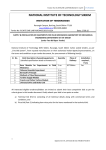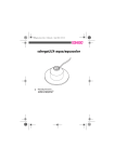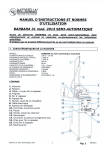
1
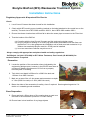
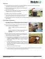
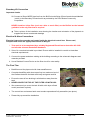
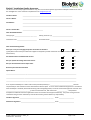
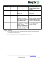
Biolytix BioPod (BF6) Wastewater Treatment System Installation, Operation and Service Guide Biolytix Limited PO Box 12 499 Penrose Auckland --‐0800 700 818 www.biolytix.com © 2012 Biolytix Limited Biolytix Guideline- Pt Boston - FINAL_V3 Final Revision: 30/10/2013 INDEX Section Page Installation instructions 2 Electrical installation manual 7 Biolytix domestic filter service checklist 14 Service manual 16 Attachment Sumo property pumps Biolytix Guideline- Pt Boston - FINAL_V3 Final Revision: 30/10/2013 After 36 Page 1 of 36 Biolytix BioPod (BF6) Wastewater Treatment System Installation Instructions Regulatory Approvals & Important Site Checks Check 1. Local Council Consent has been issued for this installation. 2. Check which BF6 model you are installing (marked on the label attached to the control box on the tank lid). The tank size of BF6 3000 models is 3000 L, that of BF6 4000 models 4000 L. 3. Ensure the chosen location has sufficient fall to allow the sewer pipe to connect to the Filter inlet. 4. That the location of the BioPod: (a) Complies with the local Council Consent and the engineering design report; (b) Is not in subject to flooding or in a low-lying area where stormwater runoff can flow over the BioPod. If it is, then postpone the installation until a flood zone tank extension kit (a 390mm riser assembly Biolytix code No. 87020) can be installed. (c) Is not an area where vehicles may drive over it. Always comply with appropriate workplace health and safety regulations. Call Biolytix Ltd (+64 9 579 1080) or E.P. Water Treatment, Port Lincoln (08 86830408) for technical advice if required. Excavation 5. Locate the position of the excavation where indicated by the engineering design report, however in the DCLEP area there is a minimum distance requirement of 2.5m from a property boundary and / or building 6. Tank inlet invert depth is 650mm for a 3000 Litre tank and 1100mm for a 4000 Litre tank 7. Mark out an area 2.4m x 2.4m square and excavate to a depth of 1.9m (3000 Litre tank) or 2.36m (4000 Litre tank) 8. Batter the sides of the excavation for safety, shore if required. Seek engineering advice if in doubt or in unstable ground conditions Base Preparation 9. Place and level a 50mm layer of fine crusher dust or sand over the base of the excavation (minimum 0.3 cubic metres) 10. Ensure base is level and free of any large objects Biolytix Guideline- Pt Boston - FINAL_V3 Final Revision: 30/10/2013 Page 2 of 36 Placement 11. Lift and place the tank using all 8 of the attached hold down cables (On the BF6 4000 a lifting strop will be required to link the eight lifting cables) 12. A tank weighs approximately 450kg and can be lifted by an appropriate excavator 13. Align the tank so that the tank inlet pipe points towards the intended position of the house sewer pipe 14. Carefully lower the tank into the excavation 15. Fill the hold-down pipes with sand/soil/fines and compact it, then tap the caps firmly onto to the ends of the pipes 16. Place the pipes centrally in the loops of the hold-down cables with the cables hanging vertically with no slack Back-filling the Excavation 17. To minimise the risk of BioPod floatation which could occur on installations with a high water table Biolytix require the following procedure to be followed: 18. Use a stiff mix (low slump) concrete to minimize risk of the tank movement during installation Option A: 20MPA (low slump) pre-mix of 2 cubic metres Option B: A stiff mix of 2 cubic meters mixed on site at 2 parts cement, 5 parts sand, and 8 parts aggregate. 19. Before concrete is poured, the tank must be filled with 900 litres of water. This provides weight to prevent movement of the tank when the concrete is poured a. Evenly place the concrete backfill around the BioPod, to a height of approx 500mm (up to the 6th rib from the bottom of the base of the tank) (minimum quantity 2 cubic metres) b. Continue backfilling the excavation from the base of the tank with clean material in 200 mm layers compacting each layer evenly with a mechanical compactor to guard against subsidence. c. Back fill to the invert of the inlet pipe d. Install inlet grommet (Uni-seal) and push the supplied inlet pipe 300mm into the tank (Note that the uni-seal is located inside the electrical control box) Biolytix Guideline- Pt Boston - FINAL_V3 Final Revision: 30/10/2013 Page 3 of 36 Boundary Kit Connection Important checks 20. Connect a 25mm MDPE pipe line from the BioPod outlet fitting (25mm female thread labelled ‘outlet’) to the Boundary Connection kit as provided by the Point Boston Community Corporation. NEVER install an inline filter (such as a disc or mesh filter) on the BioPod as the internal geofabric is the only filter that is required Take a picture of the installation now showing the location and orientation of the pipework to supplement the as constructed drawings Electrical & Alarm Connections Electrical Instruction manuals are located inside the electrical control box. Please read, complete and return the appropriate manual to Biolytix. 1. This work is to be completed by a suitably Registered Electrician to Australian AS 3000 and all other relevant Australian Standards 2. 20m of 4 core electrical cable is provided. Ensure cable is installed in conduit to Australian electrical requirements 3. Connect the power and alarm cabling at the building according to the schematic diagrams and manuals provided 4. Use a Residual Current Device on the filter circuit for extra safety The Final Trim Backfill around the pipe work with clean sand/fines etc Complete backfilling with clean topsoil up to a maximum level of the interface between the black tank body and green tank lid Ensure the area is free draining in all directions away from the tank NEVER COVER THE TOP OF THE FILTER LID WITH SOIL We recommend you cover the tank lid with a thin layer of bark mulch (as shown in photo) The control box and access hatch must remain exposed and fully accessible (see photo). Please tidy up around the installation Biolytix Guideline- Pt Boston - FINAL_V3 Final Revision: 30/10/2013 Page 4 of 36 Commissioning If power and water are not available during installation, the installer will need to return to site to commission the BioPod. Alarm & Pump tests Audio-Visual Alarm – Ensure the alarm sounds and light flashes when the high level float is raised, and that it can be muted Check pump activates when lower float switch is activated Air Pump test: Check that the air pump is running and that good air flow is delivered and all air lines are connected Ordering the Worms and Inoculating the Filter Order the worms by calling E.P. Water Treatment, Port Lincoln (08 86830408) The inoculation kit should not be ordered or placed in the filter until the BioPod is actually used for two weeks Access to the BioPod is via the green central lid and the inoculation kit should be emptied out of the bag onto the filter bed below and slightly to the side of the sewer inlet pipe. The worms should look active and not have any decaying smell. If you receive a kit that you are concerned about, please call Biolytix E.P. Water Treatment. Quality Assurance check Documents Ensure all lids and covers are closed and secured, and no screws are missing Ensure that the BioPod power is ON (a slight vibration can be felt by placing your hand on the control box) Complete and sign off on the Quality Assurance document. (These are located in the electrical control box – sample QA document on following page) Biolytix Guideline- Pt Boston - FINAL_V3 Final Revision: 30/10/2013 Page 5 of 36 Biolytix® Installation Quality Assurance This form is to be used by approved installers only, who have received specific approval from Biolytix Limited for the use of the abridged form. Scan and email completed form to [email protected] Installer’s Name: __________________________________________________________________ Owner’s Name: __________________________________________________________________ Site Address: __________________________________________________________________ __________________________________________________________________ Owner’s Contact No: ___________________________ Filter Installation Details: Filter(s) type: _____________________________ Filter(s) Serial No. (s): ___________________________ Installation Date: __________________________ Inoculation Date: ______________________________ Filter Commissioning Details: Have you or are you arranging the power connection to the filter? Yes No (If YES please ensure that your electrician supplies a Certificate of Test & Connection to confirm workmanship as per the Electrical Act) Has the filter been inoculated with worms? Yes No Did you replace the sewage line to the house? Yes No Did you decommission the old septic tank? Yes No Boundary Kit connection checked? Yes No Special Notes: _____________________________________________________________________________________________ _____________________________________________________________________________________________ _____________________________________________________________________________________________ As an experienced Biolytix® installer and licensed plumber/drainlayer, I, ______________________________ take full responsibility for the installation of this wastewater treatment plant. As such I have installed the equipment in accordance with the Biolytix® standards, Standards Plumbing and Drainage Regulation, the Local Government Approval and have used ________________________________as the licensed electrician, with License No. _____________. I completed a Compliance Certificate and have supplied this to the Local Government Approval Authority. Any issues arising from the installation being less than satisfactory and not due to faulty product will be my responsibility. Installer’s Signature: _____________________________________________ Date: ____________________ Electrician’s Signature: _____________________________________________ Date: ____________________ Biolytix Guideline- Pt Boston - FINAL_V3 Final Revision: 30/10/2013 Page 6 of 36 Biolytix BioPod (BF6) Wastewater Treatment System Electrical Installation Manual This document is required to be read prior to installation and the Quality Assurance sections completed as a part of the installation process. Please note that a failure to follow these procedures will void the Biolytix Manufacturer’s Warranty. This manual covers the following: 1. Owners and contractor details 2. Connection of Mains Power 3. Connection of an Audio-Visual Alarm Contact N2P Control Ltd if you have any uncertainty about the electrical installation. New Zealand – +64 9 570 1919 A Licensed Electrical Contractor is required to complete this procedure to Australian AS 3000 and all other relevant Australian Standards The Electrician must complete, sign and date, where applicable the following pages. This is a Biolytix Quality Assurance document that must be returned to Biolytix immediately on completion, if it is not received the Biolytix Manufacturer’s Warranty will be void. Biolytix does not accept responsibility for workmanship of the Electrical Contractor. If sub-standard electrical workmanship leads to failures within the Biolytix System, the client will be invoiced for any repairs. On completion please Scan and Email this document to: [email protected] Important: Biolytix will not issue a commissioning certificate before the completed documents are received from the client. Biolytix Guideline- Pt Boston - FINAL_V3 Final Revision: 30/10/2013 Page 7 of 36 Owners Details Full Name (Owner/Client): …………………………………………………………………………………………………………………. Site phone number: …...................................................................................................................... Site Address: ……………………………………………………………………………………………………………………………………. City/Town: …………………………………………………………………. State: ……………… Postcode: ……………………. BioPod Serial No:……………………………………………………………… Date of electrical connection: …….. / …….. / ……………… Contractors Details Electrician Name: ………………………………………………………………………………………………………………………………. License number: ……………………………………………………………………….. Company Name: ……………………………………………………………………………………………………………………………….. Mobile number: ………………………………………………………………………… Contact number: ………………………………………………………………………. Important: Please note that you must certify your workmanship by signing and dating page 6 of this document. Biolytix Guideline- Pt Boston - FINAL_V3 Final Revision: 30/10/2013 Page 8 of 36 MAINS POWER CONNECTION INSTRUCTIONS Precautions: If it is more than 20m from the house junction box to the BioPod, then a longer 3 core and earth cable will be required. Please contact EP Water Treatment (of Port Lincoln) for the required length of 3 core and earth round cable to be supplied. Only round cable is acceptable to prevent moisture entering the GPO. Failure to use round cable will void the Biolytix Manufacturer’s Warranty. The white (alarm) cable on the 3 Core and Earth cable is normally live with 240 Volts. Procedure: Unroll the connected to the BioPod and Install it with conduit in a trench from the BioPod in accordance with all relevant Australian standards and connect to the House power circuit. Photograph the power trench for depth verification. Backfill the power trench if possible to prevent water being channeled to the excavation for the tank. Biolytix Guideline- Pt Boston - FINAL_V3 Final Revision: 30/10/2013 Page 9 of 36 Electrical Installation Guide Refer to attached wiring and circuit diagram when installing the controller. All electrical work must be carried out as per AS 3000 Any problems with installation of the control unit please contact N2P Controls on +64 9 570 1919. 1) Connect the main power supply to the cable provided. Approximately 20m of cable has been provided. If this needs to be extended, please contact Biolytix 2) Install the alarm panel into a flush mounting box. 3) Connect a 240V supply to the alarm panel’s Supply terminals, P for power and N for neutral. NOTE: This power supply is to be from a different RCBO (residual current device with built-in overload) than what is supplying the controller at the tank. 4) Connect the white alarm wire from the cable that supplies power to the tank to the Controller No Fault FP (Fault Power) terminal on the alarm panel. NOTE: There is usually 240V on this wire from the Controller at the tank. Connect a neutral wire to the Controller No Fault FN (Fault Neutral) terminal on the alarm panel back to the RCBO that is supplying power to the tank. 5) Once installed power up the alarm panel and controller and complete the commissioning of the controller. To commission the system complete the tests below: a) Under normal, fault free, conditions the System OK green LED will be ON and Red Fault LED OFF. b) In a fault condition, the System OK green LED will be OFF and Red Fault LED ON. The buzzer will also sound. By pressing the mute button, the buzzer will silence until the alarm resets. A fault indication would be either a high level alarm, loss of air pressure or no power at the treatment plant. c) If both the System OK green LED is OFF and Red Fault LED is OFF there is a fault at the tank and no power at the remote alarm panel. Controller By Biolytix Guideline- Pt Boston - FINAL_V3 Final Revision: 30/10/2013 Page 10 of 36 B lu e 2.5m m Di a B ro wn 1 m m D i a B ro wn 1 m m D i a ee m n1 m B ro wn 1 m m D i a B lu e 1m m Di a Dia Whi te 2.5m m Di a Gr Biolytix Guideline- Pt Boston - FINAL_V3 Final Revision: 30/10/2013 B lu e 1m m Di a B lu e 1m m Di a R ed 2.5m m D ia 10 - Pu m p Start/S top / Iso la ti on S w itch 9 - P ressure S wi tch / B l ow er 8 - H i gh Le vel / Pressu re Sw i tch 7 - P um p S tart Fl oa t 6 - P um p P ha se Su ppl y / M a nua l S ta rt 5 - A l arm Outpu t 4 - N eu tral (P um p /B l ow er) 3 - N eu tral Su ppl y / Li g ht 2 - P ha se Su ppl y 1 - E A RT H R ed 1m m D ia R ed 1m m D ia B la ck 1 m m D i a Gre en 2.5m m D ia BIOLYTIX CONTROLLER WIRING DIAGRAM Controller Enclosure B P Controller Lid Manu al R un P ow er Su ppl y - R ed 2.5m m D ia Li gh t N eutral - Bl ac k 1 m m D i a Su ppl y In - Re d 2.5m m Di a P ow er In - R ed 2 .5 m m D i a Page 11 of 36 Alarm Panel Wiring Diagram Power and Neutral Supply from separate RCBO that supplies the tank. Controller By Biolytix Guideline- Pt Boston - FINAL_V3 Final Revision: 30/10/2013 Page 12 of 36 Control Panel Circuit Diagram B L P L Controller By Please sign and date this page. I……………………………………………………………………………………..certify that the electrical installation, to the extent it is affected by my electrical work, has been tested to ensure it is electrically safe and is in accordance with the requirements of the wiring rules and any other standard applying to the electrical installations (e.g. AS3000 and others as appropriate) and according to Biolytix instructions. Signature: …………………………………………………………………………………… Biolytix Guideline- Pt Boston - FINAL_V3 Final Revision: 30/10/2013 Date: …….. / …….. / ………….. Page 13 of 36 Biolytix Domestic Filter Service Checklist Client name/s ……………………………………………………………….. Street address ……………………………………………………………….. Town ……………………………………………………………….. Technician’s name ………………………………………………………………. Contact No ………………………………………………………………. Filter Serial No (9 digits) Date of Service Visit Q …………………………………. ……… / …….. / ……………….. NOTE: QC003 Effluent Check to be completed before disturbing the effluent Legend: √ = OK, X = NOT OK, N/A = not applicable or not done QC001 Structural Integrity 1. Filter Lid not covered by soil? 2. Filter installed to correct depth? 3. Control Box Cover drainage opening clear? 4. Lids and Covers secure (before commencing service)? 5. No evidence of condensation or moisture in the Control Box and seals appear intact? 6. 25mm connections to MDPE manifolds intact & secure? 7. No evidence of leaks or holes to allow water, insects or rodents into or out of the Tank or Control Box? 8. No evidence of soil subsidence, Tank distortion or movement? 9. No objectionable odor detectable? √ / X / N/A 10. No evidence of surface water runoff or soil into the Tank? 11. Inlet not distorted, broken or blocked? 12. No cracks, distortion or ill fitment of Pump-well Cover? QC003 Effluent Check Offsite tests (only when requested by Biolytix) Results Turbidity NTU pH Results BOD5 mg/L Suspended Solids analysis mg/L Effluent Temperature °C Faecal Coliforms CFU Dissolved Oxygen mg/L Total Nitrogen mg/L √ / X / N/A QC004 Filter Bed 1. No prolonged ponding on the surface of the Filter Bed? (more than 5 minutes after a toilet flush) 2. No blockage of Filter outlet? (record pump flow rate – it must be over 10L/min) 3. No objectionable odors detectable? 4. Accumulated plastics removed from Filter Bed? 5. Accumulated raw solids not touching the Inlet Pipe? 6. No accumulated sediment in Sump? 7. Number of top layer drainage bags (DMEs) replaced or reorganized? 8. Worm activity satisfactory? 9. Lower bed Air line fitted? ( Manometer reading? ( No.) mm water head with Schego pump on) 10. 5 minute series of (12 CFM Air compressor) air blasts performed if manometer reading above is more than 380 mm) √ / X / N/A QC005 Component Check 1. No effluent or sewage bypassing into the Pumpwell? 2. Electrical installation carried out to Biolytix installation instructions? 3. Pump operating satisfactorily? 4. Float Switches cut in/out at the correct levels consistently and without sticking? 5. Audio-Visual Alarm – Operating satisfactorily? 6. Air Pump operating satisfactorily? 7. Pipe fittings tight, with no obvious leaks? (Serial No ; if replaced, new Serial No: ) Notes: Biolytix Guideline- Pt Boston - FINAL_V3 Final Revision: 30/10/2013 Page 14 of 36 NOTE: If anything is unusual, please take a digital photograph and send to [email protected] Parts used: Please note that the servicing of each Biolytix unit at Point Boston is the responsibility of the Point Boston Community Corporation who will arrange for the annual inspections to be undertaken on the owners’ behalf. All Service Reports will be collated by the Water Services Manager who will forward completed copies of the form to: the District Council of Lower Eyre Peninsular; the Point Boston Community Corporation, and Biolytix. Office Use ONLY: Follow-up required……………………………………………………………………………………………………………………………… Unscheduled Visit created - Service Visit No ………………………… Parts ordered: SPO ……………………………………………………... Warranty (no charge) Non-Warranty (charge Service Tech) Non-Warranty (charge Installer) Non-Warranty (Charge Client) Biolytix Service Checklist – Revision 1/02/2012 Biolytix Limited - PO Box 12 499, Penrose, Auckland - 0800 700 818 www.biolytix.com © 2012 Biolytix Limited 15 Biolytix BioPod (BF6) Wastewater Treatment System Service Manual ONLY to be used by Authorised Biolytix Technicians who have appropriate training. Un-trained people must not attempt to undertake Biolytix Filter servicing. Hazards The following list shows the hazards associated with filter servicing. e. Electrocution hazard. f. Confined space hazard if entering the filter tank g. Bio-hazard from potentially infectious material associated with handling wastewater and effluent. Note: Needles & sharp objects hazard. Appropriate inoculation of workers is advised h. Trip/fall hazard associated with working on top of a tank with a sloping lid, which could be wet, and over an open filter bed. i. Environmental contamination hazard from sewerage overflow in the event of filter failure. j. Low risk potential drowning hazard within the tank during failure conditions. k. Manual handling/lifting hazard if filter bags need to be moved around in the bed or to remove bags or non-compostable items from the filter bed. l. Lone worker hazard Biolytix Limited - PO Box 12 499, Penrose, Auckland - 0800 700 818 www.biolytix.com © 2012 Biolytix Limited 16 Table of Contents Hazards............................................................................................................................................................ 16 GENERAL INSTRUCTIONS ........................................................................................................................... 18 Spare parts & equipment ............................................................................................................................. 18 Return faulty parts to Biolytix ....................................................................................................................... 19 Alarms .......................................................................................................................................................... 19 Structural Integrity Check ................................................................................................................................ 20 Effluent Quality Check ..................................................................................................................................... 23 Offsite analysis ............................................................................................................................................. 24 Filter Bed Check .............................................................................................................................................. 25 Diagnosis and treatment of Filter Bed Blockage (Hydraulic Failure) ............................................................... 28 1. Filter Overloading Symptoms .................................................................................................................. 28 2. Slow Pump Out ....................................................................................................................................... 29 3. Failed Air Supply ..................................................................................................................................... 30 4. Geofabric Blockage ................................................................................................................................. 31 Component Check ........................................................................................................................................... 32 Pump Operation ........................................................................................................................................... 32 What can go wrong?................................................................................................................................. 32 Float Switch Operation ................................................................................................................................. 32 What can go wrong?................................................................................................................................. 32 Alarm Operation – audio/visual .................................................................................................................... 34 Air Pump Operation...................................................................................................................................... 35 Measuring Bed Blockage (by Recording Bed Air Flow Resistance) 36 Biolytix Limited - PO Box 12 499, Penrose, Auckland - 0800 700 818 www.biolytix.com © 2012 Biolytix Limited 17 GENERAL INSTRUCTIONS This manual should be used in conjunction with the Biolytix service report check-sheet. A service report sheet should be completed and a copy returned to Biolytix after either a scheduled service visit to a filter or an unscheduled visit. Spare parts & equipment Spare parts Available Materials Specifications Supplier Flood zone extension ring kit PP Everhard Industries Biolytix Tank lid with control box PP Everhard Industries Biolytix Tank Access cover PP Everhard Industries Biolytix Tank Inspection opening cover PP Everhard Industries Biolytix Pumpwell lid PP Biolytix Biolytix Water meter kit Metal & Plastic 1” BSP with cam lock fittings Biolytix Electrical GPO ABS & metal 10 amp 250V Biolytix Air pressure switch box ABS & metal 250V NC pressure switch Biolytix Air pump Plastic and metal 240V 340l/hr air flow Biolytix Transfer pump Pedrollo NKm2/1 Plastic and metal 240V 40m head Biolytix Transfer pump Pedrollo NKm2/3 (high head option) Plastic and metal 240V 70m head Biolytix Float switch Plastic and metal 250 V 10 amp Biolytix Float switch swivel assembly Plastic and metal Biolytix Biolytix Push fit T 6 mm Plastic and metal Rated to 10Bar Biolytix DME bags PP & PE Biolytix 12 L volume Biolytix Limited - PO Box 12 499, Penrose, Auckland - 0800 700 818 www.biolytix.com © 2012 Biolytix Limited 18 Return faulty parts to Biolytix You must identify the client, and what your diagnosis of the fault was on the article you are returning. Disposal pumps that are removed from a Biolytix filter under warranty must be returned to E.P. Water Treatment. Return address: EP WATER TREATMENT, 124 Mortlock Terrace, Port Lincoln, SA 5606 Alarms The Biolytix system is configured to alarm in the event of any of three conditions: 1. The water level in the pump chamber is high 2. The Air supply to the pressure switch has failed 3. Power to the Biolytix tank has been interrupted When responding to a phone call from a customer experiencing an alarm condition we recommend asking the following questions: a. Have you experienced a power outage? b. Are you turning the power to the filter off? c. Is there any audible noise? d. Is there any odour? e. Has the filter been overloaded due to a party, washing day etc? f. Has the customer noticed anything that may indicate that there is a problem with their filter? g. Ask the customer to place their hand on top of the filter electrical box and a slight vibration should be felt to indicate that the air-pump is on. NOTE If a repeat alarm happens again at a regular interval it may indicate that the disposal pump cannot discharge the effluent fast enough during high loading events such as washing days to avoid triggering the alarm float switch. In this case the disposal pump and connection to the Point Boston Community reticulation system will need to be referred to / and checked by EP Water Treatment for cause (i.e. is the correct head pump installed; boundary kit operating effectively; and / or high reticulation head etc, limiting flow). Biolytix Limited - PO Box 12 499, Penrose, Auckland - 0800 700 818 www.biolytix.com © 2012 Biolytix Limited 19 Structural Integrity Check The tank is designed to receive, contain and treat only wastewater and it should not have storm-water or groundwater entering it as this may overload the systems treatment capability. Once installed the tank should not move up, down or tilt. Creatures should not enter or leave the tank through cracks or openings. The electrical box equipment must remain dry and isolated from wastewater generated corrosive gases. The sewer pipe entering the tank should grade down evenly to the tank. The pipes and conduits entering the tank must not leak or become kinked or broken. What can go wrong? 1. Tank is installed too deep in the ground (Symptoms: Ground level around the tank is not 50mm below the inspection openings; water has flooded around and or entered the control box) a. The ground level must be 70 mm below the inspection openings on the lid and must drain away from the tank lid. b. If the water cannot be made to drain away from 70mm below the inspection openings then a flood zone extension riser must be installed on the tank. 2. Tank is not installed level (Symptoms: one side of the tank is more than 40 mm lower than the other) a. May require the tank to be reinstalled. 3. Poor soil compaction around the tank (Symptoms: more than 50 mm subsidence of soil around the tank, inlet pipe can be dragged down so that it has negative fall as it enters the tank, electrical conduits or pipework can be broken or pinched, cables can be stretched or broken, tank can pop out of the ground) a. Dig down to at least uncover all pipework and conduits. b. Properly compact the soil with a mechanical compactor. c. Backfill and compact with soil in 200mm layers to the correct height d. Replace mulch to properly finish the tank. 4. Inlet is blocked (Symptoms: blockage is present in the inlet; inlet pipe is sloping the wrong way). a. Remove any non-biodegradable material and move the buildup of material to the opposite side of the filter. b. Use a sewer router if necessary to clear any blockage in the inlet pipe. c. If roots are growing into the tank through the inlet pipe then fix the sewer pipe to remove the entry point for root intrusion. 5. Hold downs not installed correctly (Symptoms: tank lifts out of the ground in wet conditions) a. Reinstall the tank. 6. Lid not fitted correctly (Symptoms: water leaking in around the lid seal, roots penetrating in between the tank and the lid) a. Remove the access cover. b. Using a torch, check for evidence of water leaking in around the tank lid rim (e.g. soil staining or root penetration). c. If there is leakage into the tank: i. Remove soil from over and around the tank lid so that the lid can be removed, cleaned and resealed onto the tank. ii. Remove and clean the lid and seal. Biolytix Limited - PO Box 12 499, Penrose, Auckland - 0800 700 818 www.biolytix.com © 2012 Biolytix Limited 20 iii. Dry the sealing surfaces and reinstall correctly, if necessary use a fresh neoprene gasket. iv. Aligning the lid over the tank so that the inspection covers are above the inlet and adjacent to the overflow. v. Installing the bolts and nuts in pairs on opposite sides of the access lid, ensuring that all screws penetrate the ribs on the tank. 7. Access cover screws stripped (Symptoms: Can’t screw down the access cover properly or remove it easily) a. Install lid threaded inserts b. Replace cover with new screws 8. Inspection opening loose or missing (Symptoms: Opening in the lid of the tank where rodents/insects can get in and out). a. Replace missing inspection covers with new ones. Twist in a clockwise direction to lock in place. 9. Lid or tank cracked or broken (Symptoms: Water, roots or creatures penetrating the tank or lid, leaks or wet spots around the tank if the tank is flooded). a. Weld or replace the damaged parts. If the tank cannot be repaired it will have to be replaced. 10. Electrical conduits can leak water, water vapor or gasses into the electrical box (Symptoms: Evidence of water having entered the control box. Discoloration of the inside of the control box from H2S gas, condensation on the lid of the control box, air pump failed with water inside it or the felt filter is wet, corrosion of the electrical wires or terminals, conduits not sealed properly with silicone as instructed in installation manual) a. Seal conduits properly with silicone sealant (use plenty and ensure it flows around all wires to give a deep and thorough water and gas tight plug. b. If the box is seriously damaged replace it. c. DO NOT TIGHTEN LID BOLT WITH TOOLS AS THIS CAN SPLIT CONTROL BOX LID. Cracked control boxes will not be covered under warranty. 11. Lid is not fitted correctly to the pumpwell (Symptoms: Lid is loose fitting and not sealed onto the pump-well. There are organic contaminants in the sump or evidence of leakage of raw wastewater down the side of the pump-well (it should be clean inside the pump-well) a. If a pump is installed: i. Turn off power at the control box. ii. Remove the Camlock fitting and elbow from the pump riser. iii. Undo the pump riser gland. iv. Remove the cover from the pump well. b. Shine a torch down the pump well and visually check that no effluent or wastewater is bypassing into the pump well or over the top rim of the pump well. c. If by passing is evident: i. Check the loading rate and/or use of toxic chemicals by the operators for the possibility of hydraulic overload or system poisoning. ii. If hydraulic overload or system poisoning is suspected, contact Biolytix. iii. Ensure the cable glands and cover seal are sound. d. Clean the pump intake. Biolytix Limited - PO Box 12 499, Penrose, Auckland - 0800 700 818 www.biolytix.com © 2012 Biolytix Limited 21 e. Re-install the pump in the reverse order. 12. Complete Section QC001 on the Biolytix Service Checklist. Biolytix Limited - PO Box 12 499, Penrose, Auckland - 0800 700 818 www.biolytix.com © 2012 Biolytix Limited 22 Effluent Quality Check The purpose of the BioPod is to treat wastewater, safely isolate biologically hazardous human waste products it contains, and remove contaminants in it so the water can be safely discharged to the Point Boston Pressure Effluent (PE) system. To ensure trouble free operation of the system an effluent with a BOD below 20 mg/L and a TSS below 30 mg/L is required. Both BOD and TSS are not easy or cheap parameters to test in the field. We have found from experience that Turbidity, Dissolved Oxygen combined with pH and temperature measurements are a low cost and instantly available range of surrogate tests that, if within the limits we specify below, will correlate very well with BOD and TSS. To collect a sample, refer to the effluent sampling procedure: 1. Measure the turbidity of the sample using the supplied portable turbidity measuring sighting tube. Lock the 2 parts of your turbidity tube together. Hold the tube vertically so you can view downwards. Gradually pour the sample that you have already collected down the inside surface of the tub until the black markings at the bottom of the tube are no longer visible. Record the measurement from the marking on the side of tube and record on the service checklist. BF6 results obtained should be < 10 NTU. If the results are greater than or equal to 20 NTU, contact Biolytix as it most likely means there is poor lower bed aeration or overloading or both. Rinse out the tube with fresh water and return to its box to minimize damage to the tube. 2. Measure the DO according to the manufacturer’s instructions in the supplied kit. Please ensure that you return the instructions to the box for future guidance. Record the DO outcome on the service checklist. (We recommend using a DO meter which can be acquired for about $1500 as these are much quicker and more accurate than DO test kits) 3. Measure the pH according to manufacturer’s instruction in the supplied kit and record the results on the checklist. (Alternatively we recommend using pH meter which can be acquired for about $100 as these are quicker and more accurate than the paper pH strips) 4. Measure the temperature of the effluent sample using the supplied thermometer. (Or for more accurate readings we recommend using a Laser Thermometer as these can give temps for the filter bed and sump from a distance without needing to touch the bed) 5. Complete Section QC005 on the Biolytix Service Checklist. Biolytix Limited - PO Box 12 499, Penrose, Auckland - 0800 700 818 www.biolytix.com © 2012 Biolytix Limited 23 Parameter Temperature Required range 15C - 35C Dissolved Oxygen Greater than 2 Turbidity Under 20 NTU pH Between 5 & 8. Troubleshooting Cold or hot climates will affect this reading, as may recent use of a dishwasher or hot bath etc. Notes Many chemical and biological reactions are affected by temp. The effluent temperature does not necessarily indicate the filter bed temperature. A low DO could indicate a lack of DO is Temperature dependant - DO aeration of the filter bed, so in Pre- decreases as temp increases and Sept 2010 units install a lower bed oxygen solubility is negatively air line in any unit that has a DO of correlated with the amount of less than 2 mg/L dissolved solids. This is an indirect indicator for suspended solids and BOD. A high turbidity is an indication that the filter bed performance is compromised. If not already present, Install a lower bed air line and test bed pressure with a manometer. (see Bed Maintenance section below) If less than pH 5 then add 2 kg of ground limestone to the filter bed around the inlet zone. If greater than 8 investigate the use of caustic household cleaners especially dish-washing machine powders, and recommend changing to surfactant based products. A high concentration of light absorbing materials such as activated carbon and dissolved colour causing substances may have a negative interference on turbidity. Suspended and dissolved solids affect turbidity. Perform test in field where possible. This is the range that worms are able to survive & reproduce. pH is temperature dependant. Offsite analysis 1. Only take a sample for offsite analysis if the it, or if it has been requested by Biolytix. local Regulatory Authority or Consent requires 2. Record results of analysis in Section QC005 of the Biolytix Service Checklist. Biolytix Limited - PO Box 12 499, Penrose, Auckland - 0800 700 818 www.biolytix.com © 2012 Biolytix Limited 24 Filter Bed Check The BioPod filter bed is the most important part of the treatment process. It screens out the solid waste entering the tank and allows the water to pass through. It should always remain open, aerobic and freedraining, and worms and other soil organisms should thrive and breed in the bed. A healthy population of worms will keep excavating small tunnels through the humus that is created from the raw wastes they process it and so the bed becomes a moist sponge like filter media with a large lung like aerobic treatment capacity. What can go wrong? 1. Bed surface swamped with too much raw organic waste (Symptoms: there is a layer of un-decomposed organic/faecal matter over the bed that is slimy and/or non-porous; perhaps with liquid ponding in low points, few if any worms are visible on the surface of the bed, it may also have a significant odour associated with the mass or raw wastes) (a) The system may be overloaded; i. Investigate the actual organic loading on the system A. number of people using the system on a regular basis (10 people max) B. number of people using the system for peak events and the number of peak events C. Take a digital photo of the bed surface and send the file to [email protected]. ii. If the system is clearly overloaded advise the owners that they must upgrade the capacity of the system to suit the loading. iii. If the system loading appears to be OK but there are reasonable grounds to doubt the loading information supplied by the owners, then the actual loading may need to be measured using a flow meter and/or BOD load monitoring. A. Contact Biolytix to discuss implementing this monitoring (b) If there is more than a 30 mm buildup of raw faecal material: i. Have the buildup of organic material removed or pumped out in a manner approved by the relevant authority. ii. Re-inoculate the bed by placing about 1kg of worms together with supplied bedding material into the inlet side of the tank. (c) If there is less than 30mm of faecal material buildup on the bed: i. Shovel the excess organic matter to the opposite side to the inlet on top of a layer of DME bags. ii. Adjust the HME Bags so that the upper bed is free draining. iii. Re-inoculate the bed. iv. If the system loading appears to be OK there may be bed conditions that inhibit biological activity – refer to section 2 below. (d) The System has a low organic breakdown rate due to poor biological activity: i. Further diagnostics are required to determine the reason for poor biological activity. ii. Measure the filter bed surface temperature at several points preferably with a digital laser Thermometer as recommended above. A. If average filter bed surface temperature is more than 35°C. Too hot for most species of worms who cease to breed and thrive above 35 °C Ensure the system is fully shaded for most of the day. Confirm that the soil temperature at 1m depth in the shade is less than 30 °C for that site. Introduce Sumatran cockroaches (or equivalent organisms that can operate at higher temperatures) into the filter. Biolytix Limited - PO Box 12 499, Penrose, Auckland - 0800 700 818 www.biolytix.com © 2012 Biolytix Limited 25 B. If the average filter bed surface temperature is less than 15°C: The filter bed may be too cold. Insulate the Lid of the tank. Cover the tank lid and surrounding soil with thick bark mulch or similar outdoor insulation material. Provide warmer source water (solar heating) to increase the thermal mass of the wastewater entering the system (this is particularly relevant for schools or public toilets operating off tank water in cold or alpine climates). iii. Toxic conditions in the filter bed – refer below. iv. The filter bed may not have enough air available for good respiration – refer below. v. The system may be too wet for good biological activity - refer to point 2 below as anaerobic decomposition in a flooded filter is very slow. 2. Filter bed may be too wet (Symptoms: Water ponding on the bed surface for more than a few minutes after a toilet is flushed, bags floating on the surface of the bed, a “tide mark” on the side wall of the tank as evidence of the level of flooding of the system, the alarm log on the installation history should show unresolved alarm events if the alarm has been working) (a) check that the alarm is working: i. If not fix the alarm as per alarm section below. ii. Discuss the responsibility for rectification with Biolytix before further action. (b) Check that the pump is working correctly: i. Discharge from the sump will be dependent upon location (i.e. elevation and distance to central Point Boston Community Treatment Facility) but should typically be in the order of 10-15L/min or more, when connected to the PE system. ii. If not fix the discharge blockage or pump operational fault before proceeding. (c) The system may be hydraulically overloaded: i. Number of people using the filter should be 10 or less. ii. Peak daily hydraulic loading rate should be less than 1600l/day. iii. Check the water usage in the house (water meter reading is the most reliable if possible). iv. If hydraulic overloading is suspected then arrange to install a water meter and data logger. A. Call Biolytix to authorize this first as there may be other factors causing the above symptoms such as: Blocked upper bed (See below) Blocked geofabric (See below) Anaerobic lower bed (See below) 3. Blocked upper bed - Upper bed pores can become blocked with too much fine organic matter washing into the pores faster than the worms present can process them (Symptoms: surface flooding evident as for section 1 above, or a layer of un-decomposed faecal matter on the surface of the bed is evident as in section 1 above, or bed air flow resistance pressure as measured using a manometer is more than 380 mm water pressure, or effluent being discharged to irrigation has a DO of less than 2 mg/L, or the lower bed is not flooded) (a) Remove plastic and other non-biodegradable waste that has accumulated in the surface of the bed over time i. Using thick gloves and a Biohazard bag, remove sanitary pads, synthetic tampons and any other obvious plastic material or non-compostable material that is on the surface of the bed, Biolytix Limited - PO Box 12 499, Penrose, Auckland - 0800 700 818 www.biolytix.com © 2012 Biolytix Limited 26 and report Misuse of Biolytix tank to EP Water Treatment for further action / owner education. ii. Dispose of this refuse in a manner approved by the local authority iii. if this is not removed it will gradually block the bed drainage and aerobic capacity (b) Adjust the DME & HME bags in the upper bed so that drainage is improved. (c) Undertake a compressed air blast of the bed. i. If there is only one air line, install a lower bed air line as described below. ii. Blast the bed with the full air flow from a standard 12 CFM air compressor (with a 20 L or more compressed air storage tank) directly to the lower bed air line. iii. Allow the pressure to build in the air compressor tank to the cut out pressure then connect to the air line at the full flow possible through the air line. iv. Measure the pressure using a manometer. v. This procedure should be repeated a few times until the manometer reading is no more than 380 mm of water head. 4. The system may have had toxic chemicals put into it at one time or may have an ongoing input of a toxic material. (Symptoms: little or no worm activity - lift 3 DMEs within 600mm of the inlet and check that there are at least 20 adult worms visible on the underside of each bag, pH is below 5 or above 8, chemical smell in the filter tank, unusually coloured material in the tank, poor drainage through the bed.) If there is any unusual biological activity, or lack of activity, photograph the area and Send the photos to Biolytix (a) Worms and other soil life in the ecosystem can be poisoned by toxic chemicals i. reduced biological activity and in particular burrowing activity by worms has a negative impact on both drainage and hence bed aeration (b) Try to determine if there is any toxic material being added to the system. i. The Owner’s Manual lists toxic household chemicals and other pollutants that must not be disposed of into the system. Check that the client is adhering to these instructions. ii. It is difficult and expensive to analyze for the range of chemicals that could be causing toxicity problems, so your nose and experience with what a normal bed should look and smell like are the best guide. (c) If toxic chemicals or other problem pollutants were or are being added, make sure the clients are aware that they will have to pay for any repairs to the bed that is necessary. 5. Excess Humus (Symptoms: Humus build-up to above the surface of the DME layer, inlet pipe can become backed up with organic matter, worms can migrate into the toilet bowl or water traps in the building) (a) Remove full bags around the inlet zone. (b) Swap them with opposite side bags. (c) When all bags on the top layer are full stack them around the outer perimeter of the inside. of the tank and replace them with fresh DME bags. (d) After 12 months of no direct contact with sewerage they can be removed and the matured worm casts shaken out and buried in a garden bed trench at 300 mm deep (or according to state of local government regulations), then the bags can be reused as DME bags. Biolytix Limited - PO Box 12 499, Penrose, Auckland - 0800 700 818 www.biolytix.com © 2012 Biolytix Limited 27 Diagnosis and treatment of Filter Bed Blockage (Hydraulic Failure) The Biolytix filter bed can fail to drain from four main causes, all of which are related to the amount of air available to the biolytic organisms in the filter bed. Filter overloading - too much water and/or organic matter. Slow Pump Out - Pump cannot remove the water as fast as it comes into the sump. Failed Air Supply to the filter bed which becomes anaerobic and slow to drain. Geofabric Filter Blockage - partially or fully blocked pores in the filter cloth. 1. Filter Overloading Symptoms i. ii. iii. iv. A large amount of un-decomposed organic matter evident on the surface of the bed. Water ponding on the surface of the bed or bags floating with or without worms on top of the bags, but with air coming up through the water. No worm activity present. Evidence of flooding to well above the level of the pump-well lid and sometimes even into the control box. Causes of Overload Action Too many (more than 10) full time people “Equivalent Persons” (EP) using the system and/or more than 1600 L/d wastewater. Reduce the number of people using the facility or augment the capacity of the system to cope with the loading Storm-water ingress through illegally connected Change the plumbing to remove all stormwater from the down pipes or storm run-off into gully traps or system. grates. Leaking cistern flush valves (can easily overload the system if not fixed) Replace faulty cistern parts – saves a lot of water too. Leaking taps, very long showers. (total water use must be under 1600 L/d Ask clients to have any leaking taps fixed – Offer to install flow control devices on showers. Too much food waste being put in (through an Insinkerator only) – more than 250 grams/person/day. Ask clients to limit the amount of food waste added. System installed in a flood plain. Contact Biolytix to discuss options for a tank extension. Pump discharge line is disconnected inside the tank. Replace any damaged fittings and refit the discharge line correctly. No obvious causes but overloading is still the prime suspect. Install a Severn Trent water meter and Tiny Tag datalogger on the outlet hose and monitor for some months. Average filter bed surface temperature is less than 15°C – too cold for good worm activity. Insulate the underside of the tank lid with PU foam and cover it with thick bark mulch to act as insulation Average filter bed surface temperature is more than 35°C - too hot for good worm activity Ensure the filter bed is fully shaded for most of the day. Confirm that the soil temperature at 1m depth in the shade is less than 30 °C for that site. Filter bed may be too toxic for good biological activity. Audit the chemicals used in the facility using the toxicity audit sheet and advise Biolytix of the outcome Not enough air for good biological activity See below under failed air supply Biolytix Limited - PO Box 12 499, Penrose, Auckland - 0800 700 818 www.biolytix.com © 2012 Biolytix Limited 28 2. Slow Pump Out If effluent in the sump is repeatedly and periodically above geofabric level of 380 mm (280 mm in pre 2005 units), then a combination of bubble point pressure in the sump, saturated geofabric or slime growth within the geofabric can eventually result in geofabric blockage. The alarm should go off every time the sump effluent level exceeds 330 mm. If there are alarms experienced almost every day or on “washing day”, then urgent attention should be given to determine the true cause of the slow discharge of effluent. Causes of Slow Pump Out Action Pump float switch is sticking. Adjust the float and or pump position to ensure the float and its cable move freely and do not touch the pump-well wall. The flow through the pump is restricted or stopped. (replace pump if stopped) Take the base off the pump and clean the impellers and make sure the motor is turning at full power. Failed capacitor or incorrect wiring will lead to greatly diminished pump capacity. Control float is fitted too high on the pump. Adjust the cut in height of the control float to be 165 mm (refer to pump replacement in the service manual) There may be ground water entering the plumbing or the Biolytix filter tank. A “soil” stain below the overflow relief drain “y” junction will be evident if a torch is shone down the inspection opening if ground water is entering here. There is also a rare possibility of ground water entering through the base of the tank if the Sump Inspection pipe is not inserted correctly into the rubber grommet. There may be hydraulic overloading of the system. Refer back to section 1 above to diagnose. The pump fitted is not correctly sized for the Fit a pump with a higher head that can deliver an appropriate head loss of the pressure as it is designed. pressure for the pressure sewer system (Pedrollo NKm2/3). Biolytix Limited - PO Box 12 499, Penrose, Auckland - 0800 700 818 www.biolytix.com © 2012 Biolytix Limited 29 3. Failed Air Supply The bed relies on air to remain aerobic and support an active worm and microbial population. If the bed becomes anaerobic, then the bed porosity will gradually decline and lead to eventual hydraulic failure. This is because the macro- and micropores in the bed are cleaned and maintained by grazing microbes, mites and worms etc. The geofabric is also continually cleaned by microbes and if the bed or geofabric becomes anaerobic, then it will soon become coated with and impregnated with biofilm slime. If this happens then the slime must be removed or the filter will fail to drain properly. Causes of Failed Air Supply Air pump has failed. Action Replace the air pump or its diaphragm. Air line to base has become kinked Follow the work instruction for “installing and commissioning a or blocked. lower filter bed air line” and then test air flow again. No air bypassing the geofabric layer into the lowest DME layer. Fit a new air line down the side of the Biopod tank to the middle of the lowest DME layer. (Ref. “installing and commissioning a lower filter bed air line”) (A) Repeated flooding of the geofabric layer due to slow pump out. Fix the slow pump discharge problem see section 2 above. (B) Bubble point back-pressure below the geofabric prevents effluent from flowing through the filter cloth under gravity Fit a second air line down the side of the BioPod tank to the middle of the lowest DME layer (Ref. “installing and commissioning a lower filter bed air line”) Flooding above the geofabric creating an air seal which prevents air escaping from the sump up though the geofabric (short pump cycling will usually be evident in this case). Test lower bed water level and if more than a 100 mm of water pressure then insert a 25 mm riser spear and use a Helical rotor pump (or other suitable suction pump) to pump down excess effluent in the bed so air can flow through the bed. This may need to be repeated a few times before the beds aerobic status is back to normal levels. DO should be 2 mg/L or higher. Upper Bed blocked – i.e. Bed air flow resistance is greater than 380mm of water head Ref: “Measuring Bed Blockage” below. Blast the bed with the full air flow from a standard 12 CFM air compressor (with a 20 L or more compressed air storage tank) directly to the lower bed air line. Allow the pressure to build in the air compressor tank to the cut out pressure then connect to the air line at the full flow possible through the Air line. This procedure should be repeated a few times until the manometer reading is no more than 380 mm of water head. Biolytix Limited - PO Box 12 499, Penrose, Auckland - 0800 700 818 www.biolytix.com © 2012 Biolytix Limited 30 4. Geofabric Blockage The geofabric is a self-cleaning filter cloth with an 80 micron pore size. The pores are kept clean through the grazing action of aerobic microbes. If the oxygen levels in the bed and the effluent are high, then the filter cloth will remain free-draining, and only very fine colloidal organic sediment will pass through in very small quantities. It can become blocked if the bed or effluent becomes anaerobic. This promotes the growth and accumulation of anaerobic microbial slime similar to a septic trench biomat. This can lead to effluent ponding on the geofabric and preventing air from getting to the lower filter bed. This is a negative feedback loop and must be corrected through deliberately supplying extra air where it is needed. This can recover the drainage capacity of the geofabric. Similarly if large amounts of grease or oils are applied to the bed, this can overwhelm the aerobic microbes and start to block the pores in the bed and geofabric. Causes of Geofabric Blockage Action Bed air supply failure. See above table. Excessive disposal of oil or grease into the Biolytix Filter. Advise users on correct operation of the BioPod – Ref BioPod User’s manual and contact Biolytix Oil and grease on or embedded in the geofabric material. Add grease consuming microbes or enzymes to clean the geofabric cloth. This may be effective if the bed is still draining at a high enough flow rate to cope with daily system loading. Repeated flooding of the geofabric layer due to slow (less than 12 L/min) pump out. Fix the slow pump discharge problem see section 2 above. Air pressure can build up in the sump and stop water coming through the geofabric. Air can be observed “burping” into the pump-well. If not present then fit a second air line down the side of the BioPod tank to the middle of the lowest DME layer. (Ref. “installing and commissioning a lower filter bed air line”) Bed blockage – i.e. Bed air flow resistance is greater than 380mm of water head as measured by a U- tube Water Manometer with air supplied to lower bed using a Schego air pump. Refer to “installing and commissioning a lower filter bed air line” Biolytix Limited - PO Box 12 499, Penrose, Auckland - 0800 700 818 www.biolytix.com © 2012 Biolytix Limited 31 Component Check Pump Operation The effluent pump is designed to transfer water from the sump to the sewer. The pump should always have power supplied to its level control float. In the up position, power is on and the pump runs. It is critical that the float switch and the pump are both operational at all times. There is a pump over-ride switch on the control box. Pressing this button bypasses the float switch and allows the pump to run irrespective of the water level in the sump. The industrial quality pump Biolytix uses can be fully repaired and refurbished, and so we require all replaced pumps to be returned to our factory for examination and repairs. This enables us to continually improve our product quality and so reduce the life cycle cost of the pumps. What can go wrong? Pump is not plugged in or wired in correctly (Symptoms: Pressing the bypass button doesn’t operate the pump or it spins weakly because the phases are not connected correctly.) (a) Double check the pump is connected correctly. (b) The capacitor may have failed – replace the pump and return the old one to Biolytix. Pump intake screen or impellers are blocked or obstructed (Symptoms: Output pressure is insufficient or low flow rate to the pressure sewer) (a) Use a pressure gauge to test the actual outlet pressure. (b) Check and clean the inlet screen so it is not fouled with organic matter that may have entered the pump well (can happen if the pump-well cover is not correctly fitted and the system floods). (c) Remove the intake screen from the pump base and remove and clean the multistage pump impellers. Pump bearing is worn out (Symptoms: Pump impeller shaft is loose. Motor rotor is polling against the case. Motor won’t start reliably). Replace the pump, it must be reconditioned before being redeployed. Under normal operation, press and hold the pump by-pass button on the control box to activate the pump (ensure the outlet line is attached to the riser and that there is sufficient effluent in the sump) Check that the level in the sump drops. The minimum discharge rate must typically be measured at more than 10 litres/min using a water meter. If the pump pressure or flow rate is found to be unsatisfactory, replace it with a stronger pump approved by Biolytix. Return all failed pumps to EP Water Treatment if under warranty. Float Switch Operation The float switch is fitted in a swivel assembly that allows it to move in a controlled arc within the pump-well without fouling on the side of the pump-well or the pump. This Biolytix designed assembly is both simple and highly reliable. What can go wrong? 1. Float switch can fail (Symptoms; will not complete the power circuit so the controlled equipment won't operate in the up position or will not stop operating when the float is in the down position) a. Replace the float switch 2. Float switch can leak and fill up with water (Symptoms: It may trip any RCD installed, pump voltage is incorrect and will not deliver the full head pressure or flow, you can hear water in the float when shaken, and multi-meter shows 10K Ohms or less Biolytix Limited - PO Box 12 499, Penrose, Auckland - 0800 700 818 www.biolytix.com © 2012 Biolytix Limited 32 resistance when float is in the up position, the float will not be as buoyant and will switch at the wrong level) a. 3. Replace the float switch as above. Stainless steel hose clamp is adjusted to the wrong height (Symptoms: Float does not cut in at 165mm and does not cut out at 60mm, the float cut-out is too low and air sucked into the pump inlet screen before the pump switches off). a. 4. Loosen the stainless steel hose clamp screw and adjust it up or down as needed then retighten it (the lower edge of the hose clamp should be 150mm up from the pump base plate. Float cable is incorrectly installed in the swivel clip. (Symptoms: Either the float or the cable catches on the pumpwell wall so that the switch does not operate reliably) 5. a. Release the swivel clip mechanism and slide the float cable in or out so that it is 20mm from the shoulder of the float to the closest edge of the swivel clip. b. Shorten the cable loop so that it just clears the pump well during its arc of movement. Float swivel clip can stick (Symptoms: Feels stiff to rotate and the float may not cut in or out at the correct levels – this is very rare with the Current PP clips). 6. a. If it does, loosen it by applying silicone grease and working it up and down several times, then replace the swivel and stainless steel M4 screw. b. If it is the old SS swivel arrangement from 2004, replace with the new PP swivel clip. Stainless steel hose clamp is loose broken (Symptoms: 316 SS hose clamp may have rusted out or broken. This is usually caused by high concentrations of caustic soda in the effluent or other harsh chemical may have been used.) a. Carefully check the body of the pump for corrosion or pitting b. Replace any parts as necessary. This is not covered under warranty as we use only marine grade stainless steel parts and the system must never have harsh corrosive chemicals used in it. Biolytix Limited - PO Box 12 499, Penrose, Auckland - 0800 700 818 www.biolytix.com © 2012 Biolytix Limited 33 Alarm Operation – Audio/Visual Warning - this alarm is powered by 240v ac. If problems are encountered when testing, a licensed electrician should carry out repairs, if the unit was produced before December 2010, otherwise the faulty parts can be unplugged, replaced and returned. 1. Activate the high-level alarm float by lifting it up with the float test rod (made by connecting a 1" MF polypropylene elbow to a 900 mm x 1" polypropylene pump riser). 2. Check that an audio/visual alarm occurs at the A/V unit. If an alarm is observed, the float switch is working. No further action is required. Reset unit. 3. Activate the air pressure switch by removing the airline from the switch. 4. Check that an audio/visual alarm occurs at the A/V unit. If an alarm is observed, the air pressure switch is working and no further action is required. Reset unit. 5. If an alarm/s is not registered check that there is power to the A/V unit and that the timer is operational. If satisfactory, split the float and air pressure switch and test for continuity across switch when activated. Replace as necessary. Biolytix Limited - PO Box 12 499, Penrose, Auckland - 0800 700 818 www.biolytix.com © 2012 Biolytix Limited 34 Air Pump Operation 1. Check for condensation in the Schego air pump and the air filter (located in the base plate of the air pump) for contamination. 2. Check the operation of the air pump by removing the airline and ensuring there is adequate airflow. 3. If operation is un-satisfactory replace pump and if under warranty return the unit to Biolytix. 4. Reconnect airline. 5. Complete Section QC004 on the Biolytix Service Checklist. Biolytix Limited - PO Box 12 499, Penrose, Auckland - 0800 700 818 www.biolytix.com © 2012 Biolytix Limited 35 Measuring Bed Blockage (by Recording Bed Air Flow Resistance) The sump air line branch of the Push Fit “T” can be removed and a U tube Water Manometer can be connected to the branch of the "T" to check bed blockage using the air flow resistance method at any time in the future. Bed Blockage The pressure required to force air flow up through the bed is critical and should remain low. If there is more than 380mm of pressure registered in the manometer with the full flow of air from the Schego air pump, then the bed above the geofabric is considered blocked. This must be corrected immediately by applying the full air flow from a standard 12 CFM air compressor (with a 20 L or more compressed air storage tank) directly to the lower bed air line. Allow the pressure to build in the air compressor tank to the cut out pressure then connect to the air line at the maximum flow possible through the 6mm air line. This procedure should be repeated a few times until the manometer reading with the Schego air pump is not more than 380 mm of water head. Provided air flow through the bed is maintained thereafter, and the tank has an acceptable worm population, the worm activity through the bed will keep the bed pores open and a manometer pressure reading below 380mm of water should be maintained in the future and no further blockage or treatment issues should be encountered. A bed with good worm activity and good air flow will typically have an air flow resistance pressure of less than 200 mm of water head. If there is bypassing of the air around the newly installed air line, then a false low air flow resistance pressure may be recorded. If it is less than 100mm this should be suspected, so fix the bypassing by settling the bed around both air lines and check that the air is not escaping before re-testing. Geofabric blockage Under normal conditions there should be no water ponding over the end of the lower bed air line. After carrying our Step 1 above, the depth of water that is ponding above the end of the lower bed air line can be measured accurately (provided it is less than the actual bed resistance as measured above). Using a short length of air line with a tap in it (you can remove the effluent sample tap temporarily for this) gradually increase the air flow until the water level in the manometer remains stable below the bed's air flow resistance pressure. This is the level of effluent that is ponding above the end of the lower bed air line. After completing this bed maintenance procedure, please recommend to the householders to use water very sparingly for a few weeks while the bed recovers its aerobic status and worms re-colonize the bed and the Geofabric's hydraulic flow rate is restored to normal. Ensure that power is restored and all pumps are operating correctly before you leave the site. Biolytix Limited - PO Box 12 499, Penrose, Auckland - 0800 700 818 www.biolytix.com © 2012 Biolytix Limited 36 ATTACHMENT SUMOm2 (SINGLE PHASE) PROPERTY PUMPS Biolytix Limited PO Box 12 499 Penrose Auckland --‐0800 700 818 www.biolytix.com © 2012 Biolytix Limited Biolytix Guideline- Pt Boston - FINAL_V3 Final Revision: 30/10/2013 Attachment