1
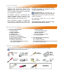
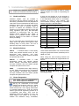
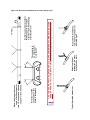
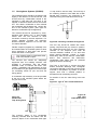
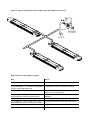
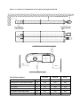
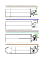
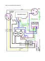
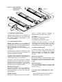
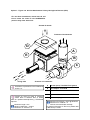
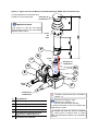
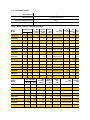
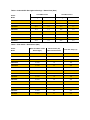
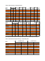
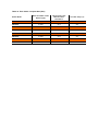
INSTALLATION INSTRUCTION MANUAL
FOR AMBIRAD VISION® VSO & VSXO
RANGE OF RADIANT TUBE HEATERS
INDEX
Section
Introduction, Document Index & Tools Required
Installation Requirements -------------------------------------------------1
User and Operating Instructions ----------------------------------------2
WARNINGS
AmbiRad equipment must be installed and maintained in accordance with the relevant
provisions of the Gas Safety (Installations and Use) Regulations 1998 for gas fired products.
Due account should also be taken of any obligations arising from the Health and Safety at
Works Act 1974 or relevant codes of practice. In addition the installation must be carried out
in accordance with the current IEE wiring regulations (BS 7671), BS 6896:2005 (Industrial &
Commercial) and any other relevant British Standards and Codes of Practice by a qualified
installer. All external wiring MUST comply with the current IEE wiring regulations.
Introduction.
Welcome to the new range of high efficiency
AmbiRad Vision radiant tube heaters. Local
regulations may vary in the country of use and
it is the installers responsibility to ensure that
such regulations are satisfied
All installation, assembly, commissioning and
service procedures must be carried out by
suitable qualified competent persons to the
statutory regulations in the country of use.
When assembling, installing, commissioning
and servicing is undertaken on radiant tube
heaters specified in these instructions, due care
and attention is required to ensure that working
at height regulations are adhered to at the
mounting heights specified.
PLEASE READ this document prior to
installation to familiarise yourself with the
components and tools you require at the various
stages of assembly.
All Dimensions shown are in mm unless
otherwise stated.
The manufacturer reserves the right to alter
specifications without prior notice.
Document Index.
1 Installation Requirements
1.1 Health & Safety
1.2 Model definitions
1.3 Heater Suspension
1.4 Wall Mounting
1.5 Herringbone systems
1.6 Clearance to Combustibles
1.7 Gas Connection & Supply Details
1.8 Electrical Connections
1.9 Ventilation Requirements
1.9.1 Unflued Radiant Heater (Type A)
Mechanical Ventilation
Natural Ventilation
1.9.2 Flued Radiant Heater
Mechanical Ventilation
Natural Ventilation
1.10 Flue & Combustion Air Inlet
1.11 Technical Details
2 User and Operating Instructions
2.1 To Start Heater
2.2 To Switch off Heater
2.3 Routine Maintenance Between Service Intervals
2.4 Frequency of Servicing
Tools required.
The following tools and equipment are advisable to complete the tasks laid out in this manual.
Suitable alternative tools may be used.
Saw
Trestles
Leather
Faced
Gloves
Pozidrive
Screwdriver
Wrench with
Extension
13mm
Socket
Tape
Measure
Pop
Riveter
& 3/16”
Rivets
Silicone
Sealant
& Gun
10mm,
12mm &
13mm
Spanners
4 & 5mm
Allen
Keys
Herringbone
Systems Only
1. Installation Requirements.
1.1
Isolate any electrical supply to the
heater and controller before proceeding.
additional steelwork should be fitted to enable
vertical hangers to be used for suspending the
heaters.
Health and Safety
If there are any doubts as to the strength or
suitability of roof steelwork to which heaters are
to be suspended, please refer to a Consultant,
Architect or owner of the building. The
recommended mounting heights for AmbiRad
heaters are given in the table below.
AmbiRad heaters must be installed in
accordance with the relevant provisions of the
Gas Safety (Installations and Use) Regulations
1998. Due account should also be taken of any
obligations arising from the Health and Safety
at Works Act 1974 or relevant codes of
practice. In addition the installation must be
carried out in accordance with the current IEE
wiring regulations (BS 7671), BS 6896:2005
(Industrial & Commercial) and any other
relevant British Standards and Codes of
Practice by a qualified installer. Isolate all
electrical supplies to the heater & controller
before proceeding.
For your own safety we recommend the use of
safety boots and leather faced gloves when
handling sharp or heavy items. The use of
protective eye wear is also recommended.
1.2
Model Definitions
VSOUT
= AmbiRad Vision U Tube Unitary
heater with painted induced burner, ID Fan,
aluminised steel reflectors, end caps,
insulation, tube over shields, painted canopies
and optional end covers.
VSOUH
= AmbiRad Vision U Tube
Herringbone heater with painted induced
burner, Damper, aluminised steel reflectors,
end caps, insulation, tube over shields, painted
canopies and optional end covers.
VSXO
= AmbiRad Vision High efficiency
U Tube heater with forced burner, recuperative
heat exchanger, aluminised steel reflectors,
end caps, insulation, tube over shields, painted
canopies and optional end covers.
1.3
Model
Recommended Mounting Height (m)
Horizontal
Inclined / wall
mounted
15
4.6 - 7.0
4.2 - 5.2
20
5.5 - 9.0
4.4 - 5.8
25
6.0 - 11.0
5.0 - 6.1
30
6.9 - 13.5
6.0 - 7.6
35
7.1 - 14.0
6.5 - 8.3
40
7.5 - 16.0
6.7 - 8.7
45
7.9 - 18.0
6.9 - 9.1
50
8.4 - 20.0
7.2 - 9.5
1.4
Wall Mounting
These radiant tube heaters can be wall mounted
using the appropriate bracket (AmbiRad part no
WMB-13-22-38).
When using the wall mounting brackets the
heater must be inclined at an angle between 30°
and 35°.
U Tube
Heater
Size
Required
angle
Chain
length
Eyebolt
position
15 - 50
30-35°
12 links
1
Figure 3.a. Angle Mounting using the Wall
mounting bracket
3.
1
Heater Suspension
The heater must be suspended by
ALL of the suspension brackets.
See fig 3.b. Attachment to the heater
support lugs should be made by a ‘speed
link’, D shackle or in the case of drop rods, a
closed formed hook. The hanging attachments
to overhead steelwork etc. must be purpose
made to good sound engineering practice or of
a proprietary type fixing. They must be
adequately fixed and designed to carry the
whole weight of the heater. In the event of
suitable roof steelwork being unavailable,
E
*
*
These angles to
be equal and not
more than 45°.
Vertical suspension chain ideal.
Where supports are inclined,
maximum recommended angle
of inclination is 15°.
Typical Speedlink attachment.
Shackle method of
attachment. Pin must
be tightened by pliers.
Drop rod with formed hook.
note. hook or eyebolt must
be closed tight.
ON U TUBE VARIANTS THE HEATER SHOULD SLOPE DOWNWARDS TOWARDS THE RETURN
BEND BY APPROX. 10mm FOR BOTH HORIZONTAL AND WALL MOUNTED INSTALLATIONS.
Vertical or inclined
suspension on this
plane is acceptable.
Where chain supports have an
angle of inclination greater
than 15° an equal and opposite
support is recommended.
15° max.
Figure 3.b. Recommended Methods of Heater Suspension.
1.5
Herringbone Systems (VSOUH).
The manifold system should be arranged to fall
slightly in the direction of the vacuum fan. This
ensures that any condensation formed in the
manifold on cold start and cool down is not
trapped or allowed to drain back into the heater
unit. This allows condensate to flow towards
the condensate trap located at the vacuum fan
end of the manifold system. (See figure 4a
below for condensate trap arrangement).
The manifold should be supported by chain,
stainless steel flexible wire, or other flexible
means from the roof structure to allow
movement caused by thermal expansion. For
100mm diameter manifold the maximum
distance between supports is 2.4m and 3.0m
for 150mm diameter.
Flexible couplers (supplied by AmbiRad) must
be inserted within the manifold system to allow
linear expansion to take place and prevent
stress and strain on the system.
The manifold must be supported either
side of the flexible coupler.
The exhaust flue should be adequately
supported from the building structure and
installed in accordance with the British
Standard Code of Practice BS 5440: Part
1:2000 – Installation and maintenance of flues
and ventilation for gas appliances of rated input
not exceeding 70kW net (1st, 2nd and 3rd
family gases)
A condensate trap assembly must be provided
at the end of the manifold system before the
hot gas vacuum fan.
‘U’ trap shall be 457mm deep. The end cap of
the collecting chamber to be fitted with a flush
flanged tank connector. Any protrusion to be
removed leaving the inside flush with end cap.
Figure 4b. Collecting Chamber Arrangement
The end cap should be sealed with silicon
jointing compound and pop riveted in position.
All condensate drains from the flue collecting
chamber to the disposal point shall be
corrosion-resistant material of not less than
22mm internal diameter. Copper or copper
based alloy shall not be used for condensation
drains. See reference BS 6896:2005.
Condensate drain pipes must be protected
against the effects of freezing.
The Type ‘0’ and Type ‘2’ vacuum fans have
bottom horizontal discharge with rectangular
connections (flanged on the type 0) and must be
mounted in that position by means of the fan
support stool onto a suitable platform or
brackets fixed to the building structure.
For details of the fan outlet fixing holes see
below.
457.0
The minimum depth of the condensate
collecting chamber shall be 305mm and the
minimum depth of the condensate drain pipe
213
190
Figure 4a.
Condensate
Trap Arrangement
305.0
Figure 4c. Type ‘O’ Fan Outlet Dimensions
Figure 4d.
Type 2 Fan
Outlet Dimensions
305.0
For details of fan mounting bracket and fixing
down holes see figure 5.
Figure 4g. Stainless Steel Telescopic
Through The Wall Arrangement (available for
Type ‘O’ and Type ‘2’ fans)
Figure 4e. Conventional Flue Arrangement
Roof Exit.
Where a conventional flue is to be installed,
AmbiRad supply an aluminium transformation
piece to which a 150mm (6ins) diameter flue
must be attached.
The length of flue which may be connected to
the fan outlet must be adequately supported
from the building structure.
Figure 4f. Conventional Flue Arrangement
Wall Exit.
Figure 5. Vacuum fan mounting details (Type ‘O’ fan illustrated)
Hole Centers
Fig 4c/d
Hole Centers
Fan
Type O
Type 2
A
124
80
B
38
35
C
175
174
D
7.1
7
E
209
125
F
153
100
G
42
25
H
239
120
J
340
210
K
332
205
L
363
215
Power (watts)
550
120
Running Current (amps)
2.6
0.8
Voltage
230V 1ph
230V 1ph
Figure 6. Typical Herringbone system (VSO shown with optional end covers)
Dos and don'ts of herringbone system
Dos
Don’ts
Check design pressure drop.
Run drains in copper or mild steel pipework.
Check for corrosive industrial process in Install system with extra 90° bends without asking
proposed building - e.g. cleaning, electroplating, AmbiRad if the system will operate correctly.
printers using sugar powder etc.
Drain all flue ducts and seal all joints.
Install flue with vertical rise without firstly fitting a
drain point at it’s lowest level.
Secure joints with pop rivets as well as sealing Fit fan with outlet vertical or with top horizontal
compound (refer to assembly instructions).
discharge.
Fit drain traps before and after fans (see figs 4).
Fit damper upside down or on it’s side.
Fit expansion joints before fan and at Fit damper wrong way round. (see fig14 page 31.)
intermediate points on the herringbone system.
Run drains in galvanised steel or plastic pipes.
Follow guide to combined flue heating system.
1.6
Clearance to Combustibles.
The minimum clearances to combustible materials are given in the tables below. These
minimum distances MUST be adhered to at all times.
Figure 7.a Diagram illustrating the clearance to combustibles (VSXO shown c/w End Covers)
B
A
F
D
C
DIM 'B'
E
DIM 'D'
DIM 'C'
VSXO
DIM 'C'
20/25
30/35/40
45/50
Above Canopy
A
100
100
100
Above Burner / Flued Heat Exchanger
B
500
500
500
Above Burner / Heater Outlet Unflued
B1
700
700
700
To the Sides
C
915
1200
1525
Below Tubes
D
2330
2330
2330
From Heater Outlet (UNFLUED)
E
570
940
940
End Wall
F
390
470
575
Figure 7.b Clearance to combustibles Vision Optima Unitary VSO UT
B
A
F
D
DIM 'B'
C
DIM 'C'
DIM 'C'
VSO UT
DIM 'C'
15/20/25
30/35/40
45/50
Above Canopy
A
100
100
100
Above Burner / Flued Heat Exchanger
B
500
500
500
Above Burner / Heater Outlet Unflued
B1
700
700
700
To the Sides
C
915
1200
1525
Below Tubes
D
2330
2330
2330
From Heater Outlet (UNFLUED)
E
570
940
940
End Wall
F
390
470
575
Figure 7.c Clearance to combustibles Vision Optima Herringbone VSO UH
B
A
F
D
DIM 'B'
C
DIM 'C'
DIM 'C'
VSO UH Herringbone
DIM 'C'
15/20/25
30/35/40
45/50
Above Canopy
A
100
100
100
Above Burner / Flued Heat Exchanger
B
500
500
500
Above Burner / Heater Outlet Unflued
B1
700
700
700
To the Sides
C
915
1200
1525
Below Tubes
D
2330
2330
2330
From Heater Outlet (UNFLUED)
E
570
940
940
End Wall
F
390
470
575
1.7
Gas Connection and Supply
to the heater not to apply excessive turning
force to the internal controls.
Before installation, check that the local
distribution conditions, nature of gas
and pressure, and adjustment of the
appliance are compatible.
A competent or qualified engineer is required to
either install a new gas meter to the service
pipe or to check that the existing meter is
adequate to deal with the rate of gas supply
required. Installation pipes should be fitted in
accordance with BS 6896:2005, so that the
supply pressure, as stated in Table 4 will be
achieved. It is the responsibility of the
competent engineer to ensure that other
relevant Standards and Codes of Practice are
complied with in the country of installation.
Pipes of smaller size than the heater inlet gas
connection must not be used. The complete
installation must be tested for soundness as
described in the country of installation.
The gas union service cock MUST be
fitted in the gas supply close to the
heater, but not onto the burner itself.
Take care when making a gas connection
A flexible hose is installed to allow safe linear
expansion of the heater without creating undue
stress on the gas supply pipe work. It is
therefore important that a tested and certified
hose assembly made to ISO 10380 2003,
supplied with ½” BSP female cone seat
adapters, is installed as per these instructions.
It is also important to ensure that expansion is
taken up in the body of the flexible hose, and
not on its attachment to the pipe work. The cone
seat adapter supplied on one end of the flexible
gas hose provides a `swivel` action, and must
be fitted on the burner using a ½” BSP barrel
nipple to provide ease of disconnection for
future servicing. This assumes that the heater
and fixed gas supply to the isolating valve have
been installed.
The installation layout described below is
the only method recommended by the
institute of gas engineers, the hose
manufacturer, and AmbiRad and must only be
carried out by a qualified/competent gas
engineer.
Figure 8. Correct Installation of Flexible Gas Connection
fig.a
fig.b
x
fig.c
x
50 +/- 20mm
fig.d
fig.e
300 +/- 50mm
Arrow
denotes direction
of expansion.
fig.f
The methods shown in fig.e and fig.f are unacceptable, due to undue stress on the hose & fittings.
Care must be taken to observe the minimum
pipe bend diameter (minimum 250mm,
maximum 350mm) & pipe expansion distance
(minimum 30mm, maximum 70mm) as shown in
fig.e.
Depending on the specific installation, the
flexible gas hose may be routed to the gas
cock at any of the following angles in relation to
the burner:
Vertical
45° angle
90° angle
(fig.a)
(fig.b)
(fig.c)
Maximum bend diameter for the 1000mm
hose is 450mm.
The correct installation as shown will allow
for approx 100mm of movement due to
expansion.
Any other position in between these angles is
acceptable.
A clearance distance ‘x’ of min 200mm
must be observed to allow side door
access .
Table 4 Gas Supply Pressures
Gas Category
I2H
I3P
Natural Gas (G20)
Propane (G31)
Max Supply Pressure (mbar)
25
45
Min Supply Pressure (mbar)
17
25
Nominal Pressure (mbar)
20
37
Gas Type
Gas Supply
1.8
Connection R½ ½in BSP Internal Thread
Electrical Connection
This appliance must be earthed.
Supply 230V 50Hz single phase.
Standard heater 116W.
Current rating 0.55 amp max (inductive).
It is recommended the heater or group of
heaters are controlled by thermostats, a time
switch and if required manual control switches
and a frost thermostat.
We recommend use of AmbiRad approved
controls. Please refer to control manual
for siting and installation details.
Fuse: external 3 amp.
Where alternative manufactures controls are
used, please refer to their instructions for their
siting and installation details.
All electrical work should be carried out to IEE
standards by a competent electrician. The
electrical connection to the heater is made by
means of a three pin plug-in power connector.
Figure 9.a Single Phase Wiring
Live, neutral and earth connections should be
made via a flexible supply cable to the power
connector and routed clear of the heater or
tubes.
The flexible supply cables should be of 0.5mm²
and comply with BS 6500:2000. The wires in
the mains lead are coloured in accordance with
the following code:
Green & Yellow Earth;
Blue Neutral;
Brown Live
Figure 9.b Typical VSOUT Induced Unitary Wiring Connections (end covers not shown)
Fused Spur
Fan plugs
into burner
Figure 9.c Typical VSOUH Herringbone Wiring Connections (end covers not shown)
Fused Spur
Figure 9.d Typical VSXO Powered Burner Unitary Wiring Connections (end covers not shown)
Fused Spur
Fan plugs
into burner
Figure 9.e Typical VSXO Powered burner Wiring Connections (end covers shown)
Fused
Spur
Fan plugs
into burner
Figure 10. Internal Burner Wiring Diagram.
Figure 10. Internal Burner Wiring Diagram.
FAN
L
GREY
VACUUM
SWITCH
N
SOLENOID VALVE
N.C.
C.
N.O.
GREEN/YELLOW
VALVE
J.S.T.
2
1
3
BLUE
EMC FILTER
GRN/YLW
MAINS INPUT
N
L
BLUE
BLUE
BLUE
MAINS
ON
GRN/YEL
BROWN
BROWN
1
2
WHITE
MAIN J.S.T.
YELLOW
GREY
9
10
3
4
7
8
11 12
PINK
IGNITER
BLUE
LAMPS
FLAME SENSOR
BURNER
ON
BLACK
WHITE
BLACK
YELLOW
GREY
BLUE
Figure 11. Typical VSO UH
Schematic Wiring
Connections
1 phase 230V
Exhaust Fan
Isolator
Tail Pipe
Isolator
Isolator
0.75mm²
Screened Cable
Isolator
Sensor
Zone A
Isolator
230V 50Hz 13A
Controller
Mains Supply
1.9 Ventilation Requirements
AmbiRad tube heaters can be operated as
flued or unflued appliances in accordance with
the relevant national requirements in the
country of installation.
vents to provide adequate ventilation, an
example of this calculation is given below:
Site Details:
20°c Internal Operating Temperature
0°c Outside Air Temperature
5m between high and low level vents
1.9.1 Unflued Radiant Heater
Radiant tube heaters can be operated as
unflued appliances so that the concentration of
Carbon Dioxide (CO2) at positions where the air
will be inhaled does not exceed 0.28%.
BS EN 13410:2001 is a guide to achieving this
requirement.
If the building air change rate exceeds 1.5 per
hour or if the heat input is less than 5W/m³, no
additional ventilation is required.
In addition to the ventilation requirements, consideration needs to be given to the possibility of
condensation forming on cold surfaces.
It should be noted that the clearance distance
around the burner increases when the unit is
operated unflued (see section 1.6). It should be
ensured that the combustion gases do not
impinge on any combustible materials.
Mechanical Ventilation
Mechanical ventilation must be installed to
meet a minimum of 1.5 air changes per hour
using appropriately sized fans and interlocked
with the heaters.
Natural Ventilation
BS EN 13410:2001 should be used to size air
Following the sizing procedure in BS EN
13410:2001 gives an air exit velocity of 1.6m/s.
This equates to a free area vent at both high
level and low level of 17.36cm²/kW free area.
1.9.2 Flued Radiant Heater
In buildings having an air change rate of less
than 0.5 per hour, additional mechanical or
natural ventilation is required. For detailed
information, please see BS6896:2005 section
5.2.2.2.1
Mechanical Ventilation
Mechanical ventilation must be installed to meet
a minimum of 0.5 air changes per hour using
appropriately sized fans and interlocked with the
heaters.
Natural Ventilation
Low level ventilation openings with a free area
of at least 2cm²/kW shall be provided. See
section 5.2.2.2.2.1.
1.10 Flue and Combustion Air Inlet Options
Induced Burners without Heat Exchangers
Please refer to Figure 12 for options.
Option 1 - Figure 12a. Air Inlet Attachments Unitary Herringbone Burners (VSO)
For non-flued installations, delete items A and
B and rotate fan outlet to the HORIZONTAL
position away from the burner.
Ducted Air Intake
Products of Combustion
D
A
E
B
C
Firing tube
Products of combustion
Ventilation requirements are as detailed in
section 1.9
Ducted air must be used in locations
where there is airborne dust or where
there is a polluted atmosphere e.g. Chlorinated
Vapours.
Maximum length = 9m
Minimum diameter = 100mm
Maximum no of bends = 2
A
127mm (5ins) Twin Wall Flue System
B
Fan Adaptor 7177-SUB
C
Fan 2501/2507 or 2560
D
Optional Ducted Air Intake. VSI-DA
E
Air Intake (supplied as standard)
Maximum flue length = 9.5m @ Ø125mm
Maximum no of bends = 2
All flues must terminate vertically.
For further information on flue runs, please refer
to BS 5440 pt.1 2000
Option 1 - Figure 12b. Air Inlet Attachments Induced Herringbone Burners (VSO)
Ducted Air Intake
C
B
A
D
Firing tube
Products of Combustion
Ventilation requirements are as detailed in
section 1.9
Ducted air must be used in locations
where there is airborne dust or where
there is a polluted atmosphere e.g. Chlorinated
Vapours.
Maximum length = 9m
Minimum diameter = 100mm
Maximum no of bends = 2
A
Induced Burner
B
Air Intake (supplied as standard)
C
Optional Ducted Air Intake. (see
notes)
D
Damper assembly
Option 2 - Figure 12c. Forced Burner with Heat Exchanger (VSXO Standard Flue)
For flued products of combustion and no ducted air
Products of combustion
L
J
K
G
G
E
H
Air
Inlet
Firing
tube
G
F
Products of combustion
Maximum flue length = 9.5m @ Ø125mm
Maximum no of bends = 2
All flues must terminate vertically.
For further information on flue runs, please refer
to BS 5440 pt.1 2000
Ducted air must be used in locations
where there is airborne dust or where
there is a polluted atmosphere e.g. Chlorinated
Vapours.
Maximum length = 9m
Minimum diameter = 100mm
Maximum no of bends = 2
E
Forced Burner
F
Heat Exchanger
G 100mm (4ins) Clips x2
H
100mm (4ins) Flexible Flue
J
100mm (4ins) Flexible Flue to Fan
K
127mm (5ins) to 100mm (4ins) Reducer
L
127mm (5ins) Twin Wall Flue Pipe
Ventilation requirements are as detailed in
section 1.9
Option 3 - Figure 12d. Forced Burner with Heat Exchanger (VSXO No External Flue)
For ducted air and products of combustion to ventilated area
J
Fresh
Air
M
G
Products of
combustion to
ventilated area
E
G
H
G
Firing
tube
F
Products of
combustion
Ventilation requirements are as detailed in
section 1.9
E
Forced Burner
F
Heat Exchanger
G 100mm (4ins) Clips x2
Ducted air must be used in locations
where there is airborne dust or where
there is a polluted atmosphere e.g. Chlorinated
Vapours.
Maximum length = 9m
Minimum diameter = 100mm
Maximum no of bends = 2
H
100mm (4ins) Flexible Flue
J
100mm (4ins) Flexible Flue to Fan
M Shroud for unflued heater installation
(supplied as standard)
Option 4 - Figure 12e. Forced Burner with Heat Exchanger (VSXO with Concentric Flue)
For flued products of combustion and
ducted air via concentric pipe.
Products of
combustion
IMPORTANT NOTE
This option is a type B23 flue system
with ducted air and is not a room sealed
balanced flue product.
Fresh
Air
Inlet
P
G
J
Fresh
Air
Products of
combustion
G
N
E
H
G
Firing
Tube
Products of
combustion
E
Forced Burner
F
Heat Exchanger
G 100mm (4ins) Clips x2
H
100mm (4ins) Flexible Flue
J
100mm (4ins) Flexible Flue to Fan
N
Flue Extension optional (see max
length) avail. 0.25m/0.5m/1.0m
P
Concentric Flue Terminal
F
Ventilation requirements are as detailed in
section 1.9
Maximum flue length = 9.5m
Maximum no of bends = 2
All flues must terminate vertically.
For further information on flue runs, please refer
to BS 5440 pt.1 2000
Ducted air must be used in locations
where there is airborne dust or where
there is a polluted atmosphere e.g. Chlorinated
Vapours.
1.11 Technical Details.
No of Injectors
1
Gas Connection
½ in BSP Internal thread
Flue Nominal Bore mm (in)
125 (5)
Unitary Fan Motor Details
230 volt 1 phase 50Hz
Table 5. Burner Settings - Natural Gas (G20)
Heater
Model
Gas Injector Injector
Flowrate Pressure
Size
Nett
(m³/hr)
(mbar)
(mm)
Heat Input kW
Gross
*Size
(h x l x w)
Fan
Fan
*Weight
Rating
Type
(Kg)
(A)
VSXO20UT
20.0
18.0
1.9
9.2
7 x 1.7
445x4120x826
104
1.0 2507
VSXO25UT
25.0
22.5
2.4
10.0
7 x 1.9
445x4120x826
104
1.0 2507
VSXO30UT
32.0
28.8
3.1
11.5
7 x 2.1
445x5955x826
142
1.0 2507
VSXO35UT
36.0
32.4
3.5
11.5
7 x 2.3
445x5955x826
142
1.0 2507
VSXO40UT
40.0
36.0
3.8
11.0
7 x 2.7
445x5955x826
142
0.5 2560
VSXO45UT
44.0
39.6
4.2
11.6
7 x 2.9
445x7760x826
182
0.5 2560
VSXO50UT
48.0
43.2
4.6
12.8 7 x 2.5L
445x7760x826
182
0.5 2560
VSO15UT
15.0
13.5
1.4
10.2
7 x 1.3
298x4049x826
97
0.5 2501
VSO20UT
20.0
18.0
1.9
11.0
7 x 1.5
298x4049x826
97
0.5 2501
VSO25UT
25.0
22.5
2.4
9.2
7 x 1.8
298x4049x826
97
0.5 2501
VSO30UT
32.0
28.8
3.1
10.8
7 x 2.0
298x5884x826
135
1.0 2507
VSO35UT
36.0
32.4
3.5
9.0
7 x 2.3
298x5884x826
135
1.0 2507
VSO40UT
40.0
36.0
3.8
8.0
7 x 2.7
298x5884x826
135
0.5 2560
VSO45UT
44.0
39.6
4.2
8.9
7 x 2.9
298x7689x826
175
0.5 2560
VSO50UT
48.0
43.2
4.6
9.1 7 x 2.5L
298x7689x826
175
0.5 2560
Gross
Nett
Gas
Flowrate
(m³/hr)
VSO15UH
15.0
13.5
1.4
10.2
7 x 1.3
298x4049x826
97
VSO20UH
20.0
18.0
1.9
11.0
7 x 1.5
298x4049x826
97
VSO25UH
25.0
22.5
2.4
9.2
7 x 1.8
298x4049x826
97
VSO30UH
32.0
28.8
3.1
10.8
7 x 2.0
298x5884x826
135
VSO35UH
36.0
32.4
3.5
9.0
7 x 2.3
298x5884x826
135
VSO40UH
40.0
36.0
3.8
8.0
7 x 2.7
298x5884x826
135
VSO45UH
44.0
39.6
4.2
8.9
7 x 2.9
298x7689x826
175
VSO50UH
48.0
43.2
4.6
9.1
7 x 2.5L
298x7689x826
175
Heater
Model
Heat Input kW
Injector
Pressure
(mbar)
Injector
Size
(mm)
*Size
(h x l x w)
*Weight
(Kg)
Note* For Optima heaters fitted with decorative end mouldings, Length increases by a further 1056mm, weight increases by 6Kg
Table 6. Induced VSO Herringbone Settings - Natural Gas (G20)
Heater
Model
Cold HB Pressure
Hot HB Pressure
mm H2O
mbar
mm H2O
mbar
VSO15UH
14.3
1.4
10.2
1.0
VSO20UH
18.4
1.8
10.2
1.0
VSO25UH
25.5
2.5
17.3
1.7
VSO30UH
14.3
1.4
10.2
1.0
VSO35UH
22.4
2.2
16.3
1.6
VSO40UH
20.4
2.0
17.3
1.7
VSO45UH
33.6
3.2
20.4
2.0
VSO50UH
33.6
3.2
20.4
2.0
Table 7. Flue details - Natural Gas (G20)
Mass Flow Rate of Flue
Gasses (kg/s)
Flue Pressure (Pa)
Max Flue Resistance
Flue Gas Temp (°C)
VSXO20UT
0.0130
19
185
VSXO25UT
0.0139
13
205
VSXO30UT
0.0165
33
180
VSXO35UT
0.0167
7.5
185
VSXO40UT
0.0183
35
220
VSXO45UT
0.0210
31
185
VSXO50UT
0.0224
10
195
VSO15UT
0.0114
6
165
VSO20UT
0.0125
19
190
VSO25UT
0.0137
28
225
VSO30UT
0.0189
29
205
VSO35UT
0.0207
24
235
VSO40UT
0.0253
28
240
VSO45UT
0.0253
26
210
VSO50UT
0.0257
27
220
Heater
Model
Tables 8. Burner Settings - Propane Gas (G31)
Heater
Model
Injector Injector
Flowrate
Pressure
Size
(l/hr)
Nett
(mbar)
(mm)
Heat Input kW
Gross
Fan
*Weight
Rating
(Kg)
(A)
*Size
(h x l x w)
Fan
Type
VSO15UT
15.0
13.9
2.18
13.5
7 x 1.0
298x4049x826
97
0.5
2501
VSO20UT
20.0
18.5
2.88
12.4
7 x 1.2
298x4049x826
97
1.0
2507
VSO25UT
25.0
23.1
3.60
13.3
7 x 1.3
298x4049x826
97
1.0
2507
VSO30UT
32.0
29.6
4.60
22.5
7 x 1.3
298x5884x826
135
0.5
2560
VSO35UT
36.0
33.3
5.12
22.4
7 x 1.4
298x5884x826
135
0.5
2560
VSO40UT
40.0
37.0
5.68
18.4
7 x 1.5
298x5884x826
135
0.5
2560
VSO45UT
44.0
40.7
6.25
14.9
7 x 1.7
298x7689x826
175
0.5
2560
VSO50UT
48.0
44.4
6.82
14.3
7 x 1.8
298x7689x826
175
0.5 202126
Heater
Model
Heat Input kW
Injector
Pressure
(mbar)
Injector
Size
(mm)
*Size
(h x l x w)
* Weight
(Kg)
Gross
Nett
Flowrate
(l/hr)
VSO15UH
15.0
13.9
2.18
13.5
7 x 1.0
298x4049x826
97
VSO20UH
20.0
18.5
2.88
12.4
7 x 1.2
298x4049x826
97
VSO25UH
25.0
23.1
3.60
13.3
7 x 1.3
298x4049x826
97
VSO30UH
32.0
29.6
4.60
22.5
7 x 1.3
298x5884x826
135
VSO35UH
36.0
33.3
5.12
22.4
7 x 1.4
298x5884x826
135
VSO40UH
40.0
37.0
5.68
18.4
7 x 1.5
298x5884x826
135
VSO45UH
44.0
40.7
6.25
14.9
7 x 1.7
298x7689x826
175
VSO50UH
48.0
44.4
6.82
14.3
7 x 1.8
298x7689x826
175
Note* For Optima heaters fitted with decorative end mouldings, Length increases by a further 1056mm, weight increases by 6Kg
Table 9. Induced VSO Herringbone Settings - Propane Gas (G31)
Model
Cold HB Pressure
Hot HB Pressure
mm H2O
mbar
mm H2O
mbar
VSO15UH
19.4
1.9
15.3
1.5
VSO20UH
22.4
2.2
17.3
1.7
VSO25UH
24.5
2.4
17.3
1.7
VSO30UH
27.5
2.7
19.4
1.9
VSO35UH
31.6
3.1
20.4
2.0
VSO40UH
38.7
3.8
23.5
2.3
VSO45UH
36.7
3.6
23.5
2.3
VSO50UH
36.7
3.6
28.6
2.8
Table 10. Flue details - Propane Gas (G31)
Mass Flow Rate of Flue
Gasses (kg/s)
Flue Pressure (Pa)
Maximum Flue
Resistance
Flue Gas Temp (°C)
VSO15UT
0.0152
12.5
182
VSO20UT
0.0200
24.9
214
VSO25UT
0.0196
15.0
232
VSO30UT
0.0201
16.2
210
VSO35UT
0.0238
27.4
240
VSO40UT
0.0255
29.9
247
VSO45UT
0.0210
31.4
233
VSO50UT
0.0334
43.6
228
Heater Model
Notes
Notes
2. User & Operating Instructions.
2.1
To Start the Heater
2.3.
Routine Maintenance between Service
Intervals
1. Ensure gas supply is turned on.
After ensuring that the heater is cold and
mains electric isolated, cleaning of the
reflectors with a soft cloth and a mild
detergent (non solvent based cleaners only)
in water can be undertaken.
2. Electrical supply to the controls is on.
3. Ensure that the controls are correctly set
i.e.;
•
•
•
Additional removal of dust from the radiant
tubes, burner and heat exchanger can be
undertaken.
Clock is correctly set.
Heater program is correctly set.
Required room temp is correctly set
4. Once the heating controller ‘calls for heat’
power will be supplied to the heater(s). The
red neon will then illuminate.
5. After a pre-purge period of 10 seconds the
burner will ignite and the amber neon will
then illuminate.
6. If lockout occurs press the lockout reset
button (if available), or switch off electrical
supply and restart after 15 seconds.
7. If lockout occurs three times consecutively
switch off and isolate the gas and
electricity supplies.
2.4
Frequency of Servicing
The manufacturer recommends that to
ensure continued efficient and safe
operation of the appliance, the heater is
serviced annually by a competent person
e.g. every year in normal working conditions
but in exceptional dusty or polluted
conditions more frequent servicing may be
required.
The manufacturer offers a maintenance
service.
Contact the AmbiRad Service department.
Details are available on request.
To Switch Off Heater
1. Switch off electrical supply to the heater.
The burner will stop and the fan will shut
off.
For Service requirements, please contact
AmbiRad.
For further technical and service support
visit our Support Information Database at
www.s-i-d.co.uk
Document reference number GB/VS/177I/1010
2.2.
2. If the heater is to be switched off for
periods in excess of one week it is highly
recommended that both the gas and the
electrical supplies are turned off.
AmbiRad Limited Fens Pool Avenue
Brierley Hill West Midlands DY5 1QA
United Kingdom.
Telephone 01384 489700
Facsimile 01384 489707
Email [email protected]
Website www.ambirad.co.uk
Technical Support www.s-i-d.co.uk
AmbiRad is a registered trademark of AmbiRad Limited. Because of continuous product
innovation, AmbiRad reserve the right to change product specification without due notice