1
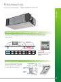
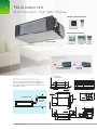
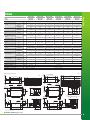
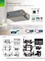
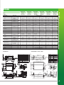
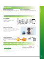
FDUA/M Series
Inverter Ducted Air Conditioners
MHIAA is proudly sponsoring
Monika’s Doggie Rescue
2
FD Series.
Inverter Ducted Air Conditioners.
A Mitsubishi Heavy Industries ducted
system lets you and your family enjoy
the comfort of powerful air conditioning
in every part of your home all year
round. Quiet, efficient and reliable our
ducted systems have a 5 year warranty
so you can be sure you’ll get quality air
conditioning for years to come.
FDUA.FDUM series Inverter Ducted Air Conditioners 2013
FDUA Indoor Unit.
Duct Connected - High Static Pressure.
Products
Automatic external static pressure (E.S.P.) control
By using a DC motor, the optimum air flow volume can be achieved by this automatic control.
The indoor unit will recognize external static pressure automatically and keep rated
air flow volume.
New
FDUA
Duct
Duct
Longer Duct
Ceiling
Keep the same
air flow volume
Setting No.
1
E.S.P. (Pa)
10 20 30 40 50 60 70 80 90 100 110 120 130 140 150 160 170 180 200
2
3
4
5
6
7
8
9
10 11 12 13 14 15 16 17 18 19
E.S.P. button
External static pressure
can be set by E.S.P.
button.
Improved servicing
Fan unit (impeller and motor) can be
pulled out from the right side of the
unit. Maintenance is available from
the right side or from beneath.
Pipe
Unit
Fan unit
Maintenance
hole
Service
space
3
FDUA Indoor Unit.
Duct Connected - High Static Pressure.
Wired Remote Control
RC-EX1A
Wireless Remote Control
RC-E5
RCH-E3
RCN-KIT3-E
Wired Remote Control
W
FduA71~160VF
RC-EX1A
RC-E5
RCH-E3
Dimension
H 398
H 280
(1) Indoor units
Model FDUA71VF
65
39
Drain can be discharged upwards by 600mm
from the ceiling surface. It allows a piping layout
with a high degree of freedom depending on the
installation location.
FDUA71VF
Unit:mm
740 Duct dimension
Symbol
A
Gas piping
B Liquid piping
C1 Drain piping
Drain piping
C2
Gravity drainage
D Hole for wiring
E Suspension bolts
F
Inspection hole
185
41
600mm Drain Pump
200 Duct dimension
FDUA100/125/140/160VF
Return air duct
Drain hose piece
Accessory
Content
15.88 5 8"
Flare
9.52 3 8"
Flare
VP25 I.D.25,O.D.32
VP20 I.D.20,O.D.26
M10
450X450
Installed on site
100
1300
Inspection
hole
55
880 Duct dimension
55
C2
30
635
510
471
413
175
280
250
105
Max. drain lift
76
D
600 or less
295 325
15
Suspension bolts pitch
43
Air supply duct
620
Note 1 The model name label
is attached on the lid
of the control box.
B
A
135
E
Under 60
FDUA.FDUM series Inverter Ducted Air Conditioners 2013
C1
69
58
67
Duct dimension
less than
600mm
472
Control box
600
Flexible hose
From bottom of unit
or more
Case 2
18
284
82
or more
18
28
Hanger plate for
suspension bolt
986 Suspension bolts pitch
950
170
4
467
30
FDUA
FDUA100VNVF
FDUA100VNXVF
FDUA125VNXVF
FDUA140VNXVF
FDUA160VSVF
FDUA71VF
FDUA100VF
FDUA100VF
FDUA125VF
FDUA140VF
FDUA160VF
Outdoor
FDC71VNX
FDC100VN
FDC100VNX
FDC125VNX
FDC140VNX
Power supply
Outdoor Unit
Cooling T1
Capacity
Heating H1
Input
FDC160VS
1 Phase 230V 50Hz
kW
3 Phase 415V 58Hz
7.1 (3.2-8.0)
10 (4.0-11.2)
10 (4.0-11.2)
12.5 (5.0-14.0)
14.0 (5.0-14.5)
16.0 (7.0-20.0)
8.0 (3.6-9.0)
11.2 (4.0-12.5)
11.2 (4.0-12.5)
14.0 (4.0-17.0)
16.0 (4.0-18.0)
18.0 (7.6-22.4)
Heating H2
5.9
10.0
13.5
14.0
15.0
15.0
Cooling T1
2.22
3.05
2.85
3.83
4.44
5.02
kW
Heating H1
2.22
2.87
2.74
3.68
4.41
4.96
3.20
3.28
3.51
3.26
3.15
3.19
EER
Cooling T1
COP
Heating H1
3.60
3.90
4.09
3.80
3.63
3.63
Indoor
P-Hi:38 Hi:33
Me:29 Lo:25
P-Hi:43 Hi:42
Me:40 Lo:37
P-Hi:43 Hi:42
Me:40 Lo:37
P-Hi:45 Hi:43
Me:41 Lo:37
P-Hi:47 Hi:40
Me:43 Lo:40
P-Hi:49 Hi:48
Me:45 Lo:42
51
49
48
48
49
57
Sound pressure level (JIS
C9612)
dB(A)
Outdoor
Sound power level (JIS
C9612)
Airflow
Outdoor
dB(A)
66
70
70
70
72
74
Indoor
l/s
P-Hi: 400 Hi: 317
Me: 250 Lo: 167
P-Hi:650 Hi:600
Me:550 Lo:483
P-Hi:650 Hi:600
Me:550 Lo:483
P-Hi:717 Hi:650
Me:600 Lo:500
P-Hi:850 Hi:800
Me:700 Lo:600
P-Hi:850 Hi:800
Me:700 Lo:600
280 x 950 x 635
398 x 1150 x 650
398 x 1150 x 650
398 x 1150 x 650
398 x 1150 x 650
398 x 1150 x 650
750 x 880(+88) x 340
845 x 970 x 370
1300 x 970 x 370
1300 x 970 x 370
1300 x 970 x 370
1505 x 970 x 370
External Static Pressure
Pa
Indoor
External dimensions
(HXWXD)
mm
Outdoor
Indoor
Net weight
Liquid line
Refrigerant piping
200
kg
Outdoor
mm
Gas line
34
52
52
52
52
52
60
81
105
105
105
140
Ø9.52
Ø9.52
Ø9.52
Ø9.52
Ø9.52
Ø12.7
Ø15.88
Ø15.88
Ø15.88
Ø15.88
Ø15.88
Ø22.22
Connection method
Refrigerant R410A
Flare Connection
kg
2.95
3.8
4.5
4.5
4.5
7.2
Pre charged to pipe
length
m
30
30
30
30
30
30
50
100
100
100
70
Maxium Pipe Length
m
50
mm
170 x 880
Return Air Connection
mm
200 x 740
348 x 898
348 x 898
Controller
RC-E5, RC-EX1 or RCN-KIT3-E
UA-SP1-E (Optional)
UA-SP2-E (Optional)
898 Duct dimension
181
VP25 I.D.25,O.D.32
M10
450X450
12.7 1 2"
22.22 7 8"
100
B
A
40
G
Under 60
or less
15
215
295 325
111
898 Duct dimension
182
181 192
C2
650
Notes 1) The model name label is attached on the lid
of the control box.
(2) Connect the piping with local pipe by using the pipe of the
attachment. Liquid side and Gas side
61
74
Air supply duct
600
472
Inspection
hole
C1
69
E
Flare
Brazing
From bottom of unit
or more
17.5
284
86
150
506
Case 2
VP25 I.D.25,O.D.32
1500
1150
C2
111
Drain piping
Drain piping
Gravity drainage
Hole for wiring
Suspension bolts
Inspection hole
Connecting position of the local pipe. liquid side
Connecting position of the local pipe. gas side
Control box
24
Duct dimension
40
Flare
or more
100
1500
Max. drain lift
or less
600
215
398
370
248
172
15
D
650
531
498
458
348
150
40
295 325
Suspension bolts pitch
Hanger plate for
suspension bolt
61
74
Air supply duct
17.5
600
650
B
A
E
24
Inspection
hole
C1
69
Under 60
Duct dimension
Suspension bolts pitch
472
Control box
Drain hose piece
Accessory
28
From bottom of unit
or more
Case 2
17.5
284
82
Flare
9.52 3 8"
26
Return air duct
1185
or more
1150
28
17.5
15.88 5 8"
Connecting position of the attached
connecting pipe liquid side
D
E
F
G
H
Installed on site
Suspension bolts pitch
Suspension bolts pitch
Connecting position of the attached
connecting pipe gas side
B
C2
Installed on site
1185
A
C1
VP25 I.D.25,O.D.32
M10
450X450
Content
Max. drain lift
Drain hose piece
Accessory
15.88 5 8"
Flare
9.52 3 8"
Flare
VP25 I.D.25,O.D.32
Symbol
181
H
D
650
531
498
458
40
398
370
248
172
24
Return air duct
Content
Duct dimension
Symbol
A
Gas piping
B
Liquid piping
C1
Drain piping
Drain piping
C2
Gravity drainage
D
Hole for wiring
E
Suspension bolts
F
Inspection hole
898 Duct dimension
348
181
Unit:mm
Model FDUA160VF
111
24
898 Duct dimension
26
111
Unit:mm
348
Duct dimension
Models FDUA100VF, 125VF, 140VF
600
Safety Pan
348
Brazed
Quantity
Supply Air Connection
Hanger plate for
suspension bolt
Products
FDUA71VNXVF
Indoor
506
Note 1 The model name label is attached
on the lid of the control box.
Outline drawing (Unit:mm)
5
Model FDUM50VF
Models FDUM60,71VF
6
With flexible set up
options, you can tailor
a Mitsubishi Heavy
Industries ducted system
to suit the needs of your
family and home. Talk to
one of our dealers today
to discuss how to design
a ducted system that’s
right for you.
FDUA.FDUM series Inverter Ducted Air Conditioners 2013
FDUM Indoor Unit.
Duct Connected - Medium Static Pressure.
Products
Automatic external static pressure (E.S.P.) control
By using a DC motor, the optimum air flow volume can be achieved by this automatic control.
The indoor unit will recognize external static pressure automatically and keep rated
air flow volume.
New
FDUM
Duct
Duct
Longer Duct
Ceiling
Keep the same
air flow volume
E.S.P. button
Setting No.
No.1
No.2
No.3
No.4
No.5
No.6
No.7
No.8
No.9
E.S.P.
10Pa
20Pa
30Pa
40Pa
50Pa
60Pa
70Pa
80Pa
90Pa 100Pa
No.10
External static pressure
can be set by E.S.P.
button.
Improved servicing
Fan unit (impeller and motor) can be pulled
out from the right side of the unit.
Maintenance is available from the right side
or from beneath.
Pipe
Fan unit
Unit
Maintenance
hole
Service
space
Reduced noise level dB(A)
Air flow sound has been reduced by a new fan and casing design.
Refrigerant flow sound was been decreased by advanced refrigerant distributor design.
FDUM50VF
FDUM60VF
FDUM71VF
FDUM100VF
FDUM125VF
FDUM140VF
5.0kW
6.0kW
7.1kW
10.0kW
12.5kW
14.0kW
NEW FDUM
26
25
25
30
30
30
Current FDUM
28
28
29
32
33
33
Improvement
-2
-3
-4
-2
-3
-3
Indoor model name
Nominal cooling capacity
7
FDUM Indoor Unit.
8
Duct Connected - Medium Static Pressure.
Wired Remote Control
RC-EX1A
Wireless Remote Control
RC-E5
RCH-E3
RCN-KIT3-E
Wired Remote Control
RC-EX1A
RC-E5
Thin design
Drain can be discharged upwards by 600mm from
the ceiling surface. It allows a piping layout with a
high degree of freedom depending on the installation
location.
The height of all FDUM models is only 280mm.
70mm less
less than
600mm
19mm less
H 350
H 299
H 280
H 280
FDUM100/125/140VF
FduM60VF
Model FDUM60VF
55
C2
76
Suspension bolts pitch
18
284
81
Control box
635
510
471
413
30
M
FDUA.FDUM series Inverter Ducted Air Conditioners 2013
4
4
Holes for
tapping screws
139
58
67
E
Air supply duct
Hole
295 325
D
55
467
262
170
880 Duct dimension
55
F
G
View M
30
Max. drain lift
30
152
124
or less
90
2" Flare
6.35 1 4" Flare
VP20 standard:I.D.20, O.D.26 or VP25 Used
with attached socket:I.D.25, O.D.34 Note 2
Drain piping
VP20 standard:I.D.20, O.D.26 or VP25
C2
Gravity drainage Used with attached socket:I.D.25, O.D.34
D
Hole for wiring
E
M10
Suspension bolts
Outside air opening
F
150 Knock out
for ducting
Air outlet opening
125 Knock out
G for ducting
H
450X450
Inspection hole
Notes 1 The model name label is attached on the lid of the control box.
2 Prepare the connecting socket VP20 or VP25 on site.
B
A
76
G
C1
69
G
600
472
F
135
139
F
170
Drain piping
113
4
4
Holes for
tapping screws
15
262
C1
4
4
Holes for
tapping screws
28
950
Liquid piping
105
31
170
31
986
18
Hanger plate for
suspension bolt
Content
12.7 1
B
90
635
510
471
413
170
30
175
Duct dimension
41
200
39
Return air duct
14
4
Holes for
tapping screw
50
15
D
680 Duct dimension
152
Hole
295 325
Drain hose piece
Accessory
Installed on site
450X450
View M
50
43
Air supply duct
Symbol
A
Gas piping
65
46
200
125 Knock out
170
Max. drain lift
E
150 Knock out
Suspension bolts pitch
135
B
A
600 or less
472
69
4
4
Holes for
tapping screws
124
C1
860 Duct dimension
4 200=800
M10
Notes 1 The model name label is attached on the lid of
the control box.
2 Prepare the connecting socket VP20 or VP25 on site.
18
284
81
28
750
58
67
170
Hole for wiring
Suspension bolts
Outside air opening
for ducting
Air outlet opening
for ducting
Inspection hole
H
Suspension bolts pitch
G
Duct dimension
Suspension bolts pitch
D
E
F
Control box
55
Drain piping
Gravity drainage
G
F
M
C2
105
786
18
Drain piping
65
46
43
Return air duct
12
4
Holes for
tapping screw
C1
12.7 1 2" Flare
6.35 1 4" Flare
VP20 standard:I.D.20, O.D.26
or VP25 Used with attached
socket:I.D.25, O.D.34 Note 2
VP20 standard:I.D.20, O.D.26
or VP25 Used with attached
socket:I.D.25, O.D.34
280
250
175
39
31
Installed on site
Gas piping
Liquid piping
Duct dimension
170
Drain hose piece
Accessory
Content
A
B
170
65
46
113
660 Duct dimension
200 200 200
31
41
200
Duct dimension
Symbol
Hanger plate for
suspension bolt
FDUM50/60/71VF
280
250
FduM50VF
Model FDUM50VF
65
46
RCH-E3
600mm Drain Pump
Flexible hose
W
C2
467
Outline drawing (Unit:mm)
Model FDUM50VF
FDUM
FDUM50ZJXVF
Outdoor
Power supply
FDUM71VNXVF
FDUM100VNVF
FDUM125VNXVF
FDUM140VNXVF
FDUM50VF
FDUM60VF
FDUM71VF
FDUM100VF
FDUM125VF
FDUM140VF
SRC50ZJX-S
SRC60ZJX-S
FDC71VNX
FDC100VN
FDC125VNX
FDC140VNX
5.0 (2.2-5.6)
5.6 (2.8-6.3)
7.1 (3.2-8.0)
10.0 (4.0-11.2)
12.5 (5.0-14.0)
14.0 (5.0-14.5)
5.4 (0.6-6.3)
6.7 (0.6-7.1)
8.0 (3.6-9.0)
11.2 (4.0-12.5)
14.0 (4.0-17.0)
16.0 (4.0-18.0)
Outdoor Unit
1 Phase 230V 50Hz
Cooling T1
Capacity
Heating H1
Input
kW
Heating H2
4.3
4.9
7.0
11.4
13.7
14.3
Cooling T1
1.56
1.75
2.20
2.92
3.60
4.40
1.70
2.00
2.20
3.20
3.90
4.54
3.18
kW
Heating H1
EER
Cooling T1
3.21
3.20
3.23
3.42
3.47
COP
Heating H1
3.18
3.35
3.64
3.50
3.59
3.52
Indoor
P-Hi:37 Hi:32
Me:29 Lo:26
P-Hi:36 Hi:31
Me:28 Lo:25
P-Hi:38 Hi:33
Me:29 Lo:25
P-Hi:44 Hi:38
Me:36 Lo:30
P-Hi:45 Hi:40
Me:34 Lo:29
P-Hi:47 Hi:40
Me:35 Lo:30
50
54
60
49
50
49
Sound pressure level (JIS
C9612)
dB
(A)
Outdoor
Sound power level
(JIS C9612)
Outdoor
dB(A)
63
64
66
70
70
72
Indoor
l/s
P-Hi: 217 Hi: 167
Me: 150 Lo: 133
P-Hi:333 Hi:250
Me:217 Lo:167
P-Hi: 400 Hi: 316
Me: 250 Lo: 166
P-Hi:600 Hi:467
Me:417 Lo:317
P-Hi:650 Hi:533
Me:433 Lo:333
P-Hi:800 Hi:583
Me:467 Lo:367
Airflow
External Static Pressure
Pa
Indoor
External dimensions
(HXWXD)
Indoor
100@400 l/s
100@600 l/s
100@650 l/s
100@800 l/s
280 x 950 x 635
280 x 1370 x 740
280 x 1370 x 740
280 x 1370 x 740
640 x 800
(+71) x 290
640 x 800
(+71) x 290
750 x 880
(+88) x 340
840 x 970 x 370
1300 x 970 x 370
1300 x 970 x 370
29
34
34
54
54
54
45
45
60
81
105
105
kg
Outdoor
Liquid line
Refrigerant piping
100@333 l/s
280 x 950 x 635
mm
Outdoor
Net weight
100@217 l/s
280 x 750 x 635
mm
Gas line
Ø6.35
Ø6.35
Ø9.52
Ø9.52
Ø9.52
Ø9.52
Ø12.7
Ø12.7
Ø15.88
Ø15.88
Ø15.88
Ø15.88
Connection method
Refrigerant R410A
Products
Indoor
FDUM60ZJXVF
Flare Connection
Quantity
kg
1.5
1.5
2.95
3.8
4.5
4.5
Pre charged to
pipe length
m
15
15
30
30
30
30
Maxium Pipe Length
m
30
30
50
50
100
100
Supply Air Connection
mm
170 x 680
170 x 880
170 x 880
170 x 1200
170 x 1200
170 x 1200
Return Air Connection
mm
200 x 660
200 x 860
200 x 860
235 x 1280
235 x 1280
235 x 1280
Controller
RC-E5, RC-EX1 or RCN-KIT3-E
FDUM71VF
FDUM100VF, 125VF, 140VF
Models FDUM100VF, 125VF, 140VF
1404
55
124
B
A
G
71
170
C1
Hole
180
104
D
1200 Duct dimension
104
C2
Max. drain lift
92
15
Air supply duct
295 325
30
600 or less
280
250
184.5
134.5
E
43
467
18
284
81
59
69
M
C2
Hole for wiring
Suspension bolts
M10
Outside air opening
150 Knock out
for ducting
Air outlet opening
G
125 Knock out
for ducting
450X450
H Inspection hole
Notes 1 The model name label is attached on the lid of
the control box.
4
4 2 Prepare the connecting socket VP20 or VP25 on site.
4
4
Holes for
Holes for
tapping screws
152 285
tapping screws
Control box
Suspension bolts pitch
30
Duct dimension
635
510
471
413
170
Drain piping
Drain piping
Gravity drainage
F
F
530
113
G
View M
90
C1
15.88 5 8" Flare
9.52 3 8" Flare
VP20 standard:I.D.20, O.D.26
or VP25 Used with attached
socket:I.D.25, O.D.34 Note 2
VP20 standard:I.D.20, O.D.26
or VP25 Used with attached
socket:I.D.25, O.D.34
D
E
Return air duct
1368
Content
Gas piping
Liquid piping
113
24.5
205
24.5
14
4
Holes for
tapping screw
18
Hanger plate for
suspension bolt
139
30
or less
880 Duct dimension
C2
76
50
D
F
105
295 325
15
Air supply duct
Hole
Max. drain lift
E
43
262
4
4
Holes for
tapping screws
170
600
472
135
Suspension bolts pitch
152
124
B
A
58
67
Duct dimension
C1
69
G
170
Installed on site
45
4
4
Holes for
tapping screws
Drain hose piece
Accessory
28
18
284
81
28
950
Suspension bolts pitch
Suspension bolts pitch
A
B
64
100
139
Air outlet opening
125 Knock out
for ducting
H
450X450
Inspection hole
Notes 1 The model name label is attached on the lid of the control box.
2 Prepare the connecting socket VP20 or VP25 on site.
Control box
55
D
E
1280 Duct dimension
4 280=1120
280
G
F
M
C1
C2
Symbol
64
100
170
986
18
Hanger plate for
suspension bolt
9.52 3 8" Flare
VP20 standard:I.D.20, O.D.26 or VP25 Used
Drain piping
with attached socket:I.D.25, O.D.34 Note 2
Drain piping
VP20 standard:I.D.20, O.D.26 or VP25
Gravity drainage Used with attached socket:I.D.25, O.D.34
Hole for wiring
M10
Suspension bolts
Outside air opening
150 Knock out
for ducting
F
Return air duct
14
4
Holes for
tapping screw
Liquid piping
175
39
31
170
Installed on site
Flare
235
Drain hose piece
Accessory
Duct dimension
B
Content
15.88 5 8"
23.5
Symbol
A
Gas piping
65
46
21.5
860 Duct dimension
4 200=800
200
31
41
200
65
46
280
250
Duct dimension
Model FDUM71VF
F
G
View M
90
738
635
468
405
170
30
467
9
10
Simple
setting by
tapping
button
only
Run / Stop
High power operation
Energy-saving operation
Maximum capacity
operation (Max 15 minutes)
• Increased compressor speed
• Increased air flow
• Changes set temperature at 28ºC in
cooling mode and 22ºC in heating mode,
25ºC in auto mode.
• Operation correction by outdoor
temperature
Main functions
Energy management
Peak cut timer • Automatic temperature set back • Weekly timer • Set ON/OFF timer by hour
• Set ON/OFF timer by clock • Fan only operation • Sleep timer
Comfort
Individual flap control • High power operation • External ventilation ON/OFF • Warm up operation
Automatic fan speed • Temperature increment setting by 0.5ºC
FDUA.FDUM series Inverter Ducted Air Conditioners 2013
Easy operation
coNtroL
Advanced touch screen panel with full dot Liquid Crystal Display
All settings done by tapping touch screen panel
Operation mode setting screen
Setting temperature screen
The operation mode can
be selected by simply tapping
this button.
You can select the desired
temperature by tapping the ▲▼
button.
Operation mode
Cooling
Dry
Auto
Fan
Heating
Convenience
LCD contrast setting • Back light setting • Filter clean sign • Control sound • Outdoor silent mode
• Summer time setting • Home leave mode • Indoor & outdoor temperature display
• Heating standby display • Defrosting operation display • Auto cooling/heating display
• ºC/ºF display • Administrator settings • Room name setting
Service
Error code display • Operation data display • Next service data display • Contact company display
• USB connection (mini-B)
11
12
Advanced Technology.
Our advanced technology has allowed us to achieve high efficiency, powerful
heating and long distance refrigerant piping specifications.
This feature permits installation of the units when a heating operation under
temperature conditions down to -20˚C is required. Design flexibility has been
improved by an extension of the refrigerant piping length to 100m (12.5 & 14.0kW).
Blue
Fin
Micro
5.0 & 6.0kW
7.1kW
Blue
Fin
10.0kW
Long piping (in case of 12.5 & 14.0kW)
Height
difference
(Outdoor higher
than Indoor)
Piping
length
30m
12.5 & 14kW
Strong heating (in case of 7.1~14.0kW)
-20C
-15C
: Heating operation down to -20C
: Nominal heating capacity maintained at -15C
Heating
-20C
-30
-20
+20C
Cooling
-15C
100m
FDUA.FDUM series Inverter Ducted Air Conditioners 2013
16kW
-10
0
10
20
+43C
30
40
50
Powerful heating capacity
Heating capacity (in case of 12.5kW)
(kW)
18.0
Keeping nominal heating
capacity at -15C
14.5
14.0
Hyper Inverter
-15C
Hyper Inverter
40C
nominal
heating
capacity
14.0kW
2C
Heating capacity
50C
30C
Micro Inverter
8.8
0
Temperature of supply air can reach
40C in 4 minutes after start up under
low temperature operation conditions
(at both indoor and outdoor
temperature of 2C) and can reach
50C in 8 minutes after that.
FEAturEs
Maximum heating capacity has been increased by optimising
refrigeration control, the use of electronic expansion valves and
our twin rotary compressors.
The Hyper Inverter series can reach the set temperature very
quickly. Normal heating capacity can be maintained when the
outdoor temperature is -15°C. It is very effective for use in cold
areas.
20C
7C
Micro Inverter
10C
Micro Inverter
0C
4minutes
8minutes
Compact design of outdoor units
FDC100VN 10.0kW
Our single fan micro 10.0kW condenser is one of the most
compact in the industry being only 845(h)x970(w)x370(d)
Size reduction and high efficiency
performance of the DC twin rotary
compressor
Outside diameter of shell
ø185mm
Former
compressor
Reduction in height by 22.3%
Reduction in volume by 44.1%
ø133mm
Height at 342mm
Height at 440 mm
The DC twin rotary compressor can operate at speeds
as high as 120 rps to achieve the required capacity.
Vector control provides perfect compressor control.
Starting current has reduced significantly and vibration
has been minimized.
New model
DC rotary compressor
* Vector control:
To convert the current
wave to a smooth
sinusoidal waveform.
Improved efficiency of the
heat exchanger
Re-designing the fins to a straight shape has
reduced the pressure loss of the air flow in the heat
exchanger. A new surface treatment on the fins has
enhanced the frost resistance capacity compared to
former models. A high speed fan motor has
increased the airflow which allows cooling capacity
to be maintained
even at high outdoor
air temperatures.
Former model
Current model
Protection
Improved operation of the electronic expansion
valve allows for more reliable oil return and this
assists to protect the compressor.
13
14
Hyper Inverter Outdoor Unit.
5.0~16.0kW.
Micro
SRC50ZJX-S
SRC60ZJX-S
FDC71VNX
FDC100VN
FDC125VNX
FDC140VNX
Blue Fin 7.1-14.0kW
Due to application of blue coated fins
(KS101) for the heat exchanger of the new
outdoor unit, corrosion resistance has been
improved compared to previous models.
FDC160VSX
Base heater kit (option)
This kit is recommended to be used in an area where the
temperature drops below 0˚C.
Blue
Fin
CW-H-E
applied for FDC100VN
FDC125~140VNX
Installation workability
Enhanced installation workability thanks to the extended pipe length – one of the longest
levels in the industry. Units are pre-charged with refrigerant.
Piping length–100m (Hyper Inverter 12.5~14.0kW)
Micro Inverter
Height difference
Height difference
(Outdoor higher than Indoor)
(Outdoor higher than Indoor)
Piping
length
Piping
length
Piping
length
Height
difference
5~6
30m
20m
7.1
50m
30m
12.5~14
100m
30m
16
70m
30m
kW
kW
10
Piping
length
Height
difference
50m
30m
Refrigerant precharged piping length extending to 30m
Refrigerant precharged piping length extends up to 30m. (5.0 & 6.0kW up to 15m)
This eliminates the need to add refrigerant on site, which sets it free from the trouble of
excessive or insufficient charging of refrigerant and allows carrying out the installation
smoothly.
FDUA.FDUM series Inverter Ducted Air Conditioners 2013
High efficiency
Increase of heat transfer efficiency
Heat transfer efficiency has improved by using
high efficiency piping and by the redesign of the
heat exchanger from 2 to 1 piece.
FEAturEs
Reduction of air flow pressure loss
Pressure caused by air flow in the indoor unit
is reduced by making the air outlet larger.
The reduction of pressure reduces the load
on the fan motor so efficiency increases.
Convenience
CnT terminal
XR2
XR3
XR4
XR5
output1 (run)
output2 (heat)
output3 (comp on)
output4 (alarm)
in put
Power
source
CnT
A dry contact is fitted to each indoor
unit which is used when a signal
output is required.
common
XR1
XR2
XR3
XR4
XR1
XR5
XR1~5 : approx. DC12v
Monitoring Function
Condensers are fitted with RS232C so you
can connect directly to your PC for monitoring.
MHI service software, Mente PC makes
service tasks simple.
Remote control RC-E5
The new remote control for all indoor units.
Non-polar 2 core wiring is used. Installation
is easier.
Previous
3-core
Current
2-core
All models employ R410A with RoHS* directive
Employment of lead free solder
Adapt to RoHS
In order to comply with RoHS standard, the new inverter
series use lead free solder.
Employment of
refrigerant
All models of the FD inverter series use
refrigerant R410A characterized by the
ozone depletion coefficient being 0.
*"RoHS" is the abbreviation of the new European standard, which
means Restriction of Hazardous Substances.
15
Before starting use
Heating performance
Refrigerant leakage
The heating performance values (kW) described in catalog are the values
obtained by operating at an outdoor temperature of 7C and indoor temperature
of 20C as set forth in the ISO Standards. As the heating performance decreases
as the outdoor temperature drops, if the outdoor temperature is too low and the
heating performance is insufficient, use other heating appliances as well.
The refrigerant (R410A) used for Air conditioner is non-toxic and nonflammable
in its original state.
However, in consideration of a state where the refrigerant leaks into the room,
measures against refrigerant leaks must be taken in small rooms where the
tolerable level could be exceeded. Take measures by installing ventilation
devices, etc.
Indication of sound values
The sound values are the values (A scale) measured in a chamber such as an
anechoic chamber following the ISO Standards. In the actual installation state,
the value is normally larger than the values given in the catalog due to the effect
of surrounding noise and echo. Take this into consideration when installing.
Use in oil atmosphere
Avoid installing this unit in as atmosphere where oil scatters or builds up, such
as in a kitchen or machine factory.
If the oil adheres to the heat exchanger, the heat exchanging performance will
drop, mist may be generated, and the synthetic resin parts may deform and
break.
Use in acidic or alkaline atmosphere
If this unit is used in acidic atmosphere such as hot spring areas having high
level of sulfuric gases or in alkaline atmosphere including ammonia or calcium
chloride, places where the exhaust of the heat exchanger is sucked in, or at
coastal areas where the unit is subject to salt breezes, the outer plate or heat
exchanger, etc., will corrode. Please ask a dealer or specialist when you use an
air conditioner in places differing from a general atmosphere.
Use in snowy areas
Take the following measures when installing the outdoor unit in snowy areas.
Snow prevention
Install a snow-prevention hood so that the snow does not obstruct the air intake
port or enter and freeze in the outdoor unit.
Snow piling
In areas with heavy snow fall, the piled snow could block the air intake port. In
this case, a frame that is 50cm or higher than the estimated snow fall must be
installed underneath the outdoor unit.
Automatic defrosting device
If the temperature is low, and the humidity is high, frost will stick to the heat
exchanger of the outdoor unit. If use is continued, the heating performance will
drop. The “Automatic defrosting device” will function to remove this frost.
After heating for approx, three to ten minutes, it will stop, and the frost will be
removed. After defrosting, hot air will be blown again.
Servicing the air-conditioner
Use in places with high ceilings
If the ceiling is high, install a circulator to improve the heat and air flow
distribution when heating.
After the air-conditioner is used for several seasons, dirt will build up in the
air-conditioner causing the performance to drop. In addition to regular servicing,
we recommend the maintenance contract (charged for) by a specialist.
Safety Precautions
Air-conditioner usage target
Installation
The air-conditioner described in this catalog is a dedicated cooling/heating
device for human use.
Do not use it for special applications such as the storage of foodstuffs, animals
or plants, computer server rooms, precision devices or valuable art, etc.
This could cause the quality of the items to drop, etc.
Do not use this for cooling vehicles or ships. Water leakage or current leaks
could occur.
Always commission the installation to a dealer or specialist. Improper
installation will lead to water leakage, electric shocks and fires.
Make sure that the outdoor unit is stable in installation. Fix the unit to stable
base.
Before use
Always read the “User,s Manual” thoroughly before starting use.
Usage place
Do not install in places where combustible gas could leak or where there are
sparks.
Installation in a place where combustible gas could be generated, flow or
accumulate, or places containing carbon fibers could lead to fires.
Only persons that are qualified and licensed are permitted to install and service products that contain refrigerants in Australia, go to www.arctick.org.
Suitable access for service must be provided in compliance with industry standards and local regulations.
MHIAA is proudly sponsoring
Monika’s Doggie Rescue
Australia:
New Zealand:
ABN 92 133 980 275
G.S.T. 105-673-620
Phone: 1300 138 007
Fax: 1800 644 329
NSW & Head Office
Victoria
Queensland
Western Australia
Phone: 0800 138 007 Fax: 09 442 5346
Auckland
9C Commercial Road
Kingsgrove NSW 2208
PO Box 318 Kingsgrove
NSW 1480
2/24 Lakeside Drive
Burwood East
VIC 3151
5/26 Flinders Parade
North Lakes
QLD 4509
Unit 3A 2 Mulgul Rd
Malaga WA 6090
PO Box 667 Belmont
WA 6104
Unit 2 100 Bush Road
Albany 0632
PO Box 300552
Albany 0632
www.mhiaa.com.au
www.mhiaa.co.nz
MrE sPArE PArts
www.mrespareparts.com.au Tel: +61 (0) 2 9600 7444 Fax: +61 (0) 2 9600 8044
ISO9001
ISO14001
BIWAJIMA PLANT
Mitsubishi Heavy Industries, Ltd.
Air-conditioning & Refrigeration Systems Headquarters
Certified ISO 9001
Certificate number : JQA-0709
MITSUBISHI HEAVY INDUSTRIESMAHAJAK AIR CONDITIONERS CO., LTD.
Certified ISO 9001
Certificate Number : 04100 1998 0813
Our Air Conditioning &
Refrigeration Systems
Headquarters has been
assessed and found to
comply with the
requirements of
ISO14001.
ISO 14001
Certificate 04104 1998 0813 E5
BIWAJIMA PLANT
Mitsubishi Heavy Industries, Ltd.
Air-conditioning & Refrigeration Systems Headquarters
Certified ISO 14001
Certificate number : JQA-EM0256
MITSUBISHI HEAVY INDUSTRIESMAHAJAK AIR CONDITIONERS CO.,LTD.
Certificate Number : 04104 1998 0813 E5
Because of our policy of continuous improvement, we reserve the right to make changes in all specifications without notice. E&OE.
MHIAA314_FD 12_2012
Our Air Conditioning &
Refrigeration Systems
Headquarters is an ISO9001
approved factory for residential
air conditioners and
commercial-use air
conditioners (including heat
pumps).