1
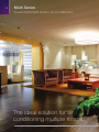
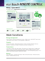
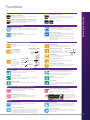
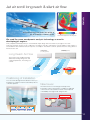
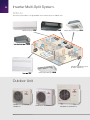
Multi Series
Inverter Multi-Split System Air Conditioners
MHIAA is proudly sponsoring
Monika’s Doggie Rescue
2
Multi Series
Inverter Multi-Split System Air Conditioners.
The ideal solution for air
conditioning multiple rooms
MULTI series Air Conditioners 2013
WELCOME
A home typically has many areas such as bedrooms, living
spaces and study rooms. Therefore, to provide total comfort
for your home, a multi-split system is recommended so each
room can have its own air conditioner.
This can be achieved through a Mitsubishi Heavy Industries
inverter multi-split system which delivers optimum
heating or cooling for everyone, no matter where they are
in the home and no matter what size the room may be.
Silent, powerful, energy efficient and utilising advanced
technologies, a Mitsubishi Heavy Industries inverter multisplit system is the solution for homes with many rooms and
occupants.
3
4
Compact
A Mitsubishi Heavy Industries inverter multi-split system allows 2 to 6 indoor units to be connected to a single
outdoor unit. This allows multiple rooms to be conditioned without adding clutter to the exterior of your home.
One compact multi-split outdoor unit instead of many outdoor units not only adds to the ascetic appeal your
home but can be imperative when there is not much space available, for example, when installing outdoor units
on balconies or verandahs.
Installation Flexibility
With a generous maximum piping length of 70m*, you are given greater freedom to decide where the indoor
units will be installed to optimise interior space and convenience. In addition, a maximum height difference of
25m* for the indoor units means the Mitsubishi Heavy Industries inverter multi-split system can easily service
the rooms for multi storey homes.
Variety of Indoor Units
The indoor unit range includes wall mounted, floor standing, low static bulkhead or compact cassette types in
a wide range of capacities. This makes hundreds of combinations possible for your home. You can choose the
right type of indoor unit to complement the interior décor and match the size of each room.
*Please check model specifications as these pipe lengths and height differences do not apply to all models.
MULTI series Air Conditioners 2013
MULTI CONCEPT
Independent Control and Comfort
Each indoor unit comes with its own remote allowing the unit to be independently switched on/off and have the
temperature adjusted as needed. The conditions of rooms can vary greatly depending on many variables such
as the number of occupants or the way the room is used. With a range of comfort, air flow and convenience
functions on each indoor unit, you can adjust the settings to match the requirements of a room without
affecting other ones. When a room is unoccupied you can switch off the unit to reduce inefficient energy use.
5 Year Warranty
When you buy a Mitsubishi Heavy Industries inverter multi-split system, you are getting an air conditioning
solution from a company that some of the highest quality products in the industry. Mitsubishi Heavy Industries
enjoys a reputation for outstanding quality and is highly respected both in the Australian and overseas markets.
With our 5 Year Warranty covering the parts, labour and compressor, you can peace of mind that your new
Mitsubishi Heavy Industries inverter multi-split system will continue to deliver air-conditioning comfort to your
home through the years.
5
6
Easy operation
All settings done by tapping touch screen panel
Operation mode setting screen
Setting temperature screen
The operation mode can
be selected by simply tapping
this button.
Operation mode
Cooling
Dry
Auto
Fan
Heating
You can select the desired
temperature by tapping the ▲▼
button.
Main functions
Energy management
Peak cut timer • Automatic temperature set back • Weekly timer • Set ON/OFF timer by hour
• Set ON/OFF timer by clock • Fan only operation • Sleep timer
Comfort
Individual flap control • High power operation • External ventilation ON/OFF • Warm up
operation • Automatic fan speed • Temperature increment setting by 0.5ºC
Convenience
LCD contrast setting • Back light setting • Filter clean sign • Control sound • Outdoor silent
mode • Summer time setting • Home leave mode • Indoor & outdoor temperature display
• Heating standby display • Defrosting operation display • Auto cooling/heating display • ºC/ºF
display • Administrator settings • Room name setting
Service
Error code display • Operation data display • Next service data display • Contact company
display • USB connection (mini-B)
MULTI series Air Conditioners 2013
Functions.
Filter
Allergen
SUN
Filter
Photocatalytic Washable Deodorizing Filter
It keeps air fresh by deodorizing the molecules causing odor.
The deodorizing ability can be easily restored simply by cleaning
and exposing the filter to the sunlight.
Enzyme
Filter
Allergen Self Clean
"HI POWER" Operation
The unit can operate continuously in HI POWER mode for 15 minutes.
This mode is used to reach the desired temperature quickly.
Automatically the unit determines its operating mode and temperature
setting based on a fuzzy calculation and adjusts the inverter frequency.
St
The air conditioner automatically selects from heating, cooling or
dry operation.
Comfortable Air Flow Functions
3D Auto
You can choose the best heating or cooling pattern with the touch
of a button.
COOLING & DRY
Horizontal blowing
The unit automatically
selects the optimal angle
whatever the operation
mode.
HEATING
Slant forward
blowing
t
ur
t Sp
ar
Automatic Operation
Auto Flap Auto Flap Mode
3HOT
Keep
The swing of the flap
causes the air flow to
spiral and the breeze
to reach all corners of
the room.
COOLING & DRY
Thick line
: moves quickly
Thin line
: moves slowly
HEATING
Thick line
Thin line
: moves quickly
: moves slowly
Three "Hot" System
‘Hot start’ enables the unit to begin heating operation quickly.
‘Hot spurt’ is a fast heating system that works to increase the
temperature setting by two degrees.
‘Hot keep’ is used during the automatic defrost cycle to prevent
cool air being circulated.
These three operational control systems help ensure comfortable
and efficient heating.
Memory Memory Flap
While the flap is swinging it can be stopped at any angle. The flap
returns to this position next time the unit starts.
UP/DOWN Up/Down Flap Swing
SWING FLAP
Flap moves up and
The Up/Down flap can be adjusted
down
to the preferred angle anywhere
between horizontal and perpendicular. continuously.
Lateral
Swing
Air Scroll Air Scroll
See details on page 2.
System Operation
Comfortable Functions
Fuzzy Auto Mode
Auto
Natural Enzyme Filter
Enzymes used in the filter are naturally occurring lytic enzymes
which attack cell walls of microorganisms trapped on the filter
and destroy them.
CONTROL & FUNCTIONS
Filter
Allergen Clear Filter
The filter breaks down the pollen, lice, and all allergens that live on
cat skins, etc. and deactivates them.
Lateral Swing
The louver swings from right to left automatically. Louver angle
can be fixed in any desired position.
Air outlet Air Outlet Selection
selection Both lower and upper air outlets and upper air outlet can be
selected. (SRF models only)
Positioning
of
installation
Positioning of Installation
You can set the left-right air flow directions when you install the air
conditioner near the side wall by remote controller operation.
Convenience & Economy Functions
24-hour On/Off Programmable Timer
On Timer On Timer
This enables the operation to start a little earlier so that the room is
near to the set temperature at ON time.
Economy Economy Mode
The unit achieves effective energy saving operation while still keeping
a comfortable cooling or heating operation.
Dry Operation
DRY
24h Timer
By combining a start timer with a stop timer you can register two
timer operations a day. Once set timers will start or stop the
system at the specified time of the day repeatedly.
OFF Timer Off Timer
The unit stops at the specified time.
Sleep
Sleep Mode
The room temperature is automatically controlled during the set
sleep mode period ensuring that the room temperature will not
get too hot or cold.
The unit dehumidifies the room by intermittent cooling operation.
Maintenance & Prevention Functions
MC
Microcomputer-Operated Defrosting
This function automatically eliminates frost and helps minimize
excessive operation in other modes.
Detachable Detachable Indoor Air Inlet Panel
The air inlet panel on the indoor unit opens and closes easily
making filter cleaning simple. The suction panel can be easily
removed.
Self-Diagnostic Function
Self
Diagnostic If the air conditioner malfunctions an internal microcomputer runs a
When removing the air inlet
panel for internal cleaning or
other reasons, open the grill
by 65 degrees and then pull
it to the side.
self diagnosis. Inspection and repair should be performed by
authorized dealers.
Others
Back-up Back-up Switch
Switch On the indoor unit there is a back up on/off switch. The system will
operate in the previous mode.
Auto Auto Restart Function
Restart Power blackout auto restart function records the operational status of
the air conditioner immediately prior to being switched off by a power
supply interruption. The unit automatically resumes operations in the
mode and temperature set point after the power has been restored.
24-hour ION
24h ION
Luminous
The air conditioner body has a tourmaline coated sheet. Negative
ions (2,500 -3,000/cc) are generated when the air conditioner is not
running, allowing you to experience them without incurring any
electrical cost.
Luminous Button
With wireless “Luminous” remote controls that even “glow in the
dark”, it is possible to operate all desired functions of the unit with
the click of a button.
7
High Efficiency.
DC PAM inverter
New inverter control
(Vector control)
An inverter system has a number of advantages over a
constant speed system. Its variable speed compressor
outputs can ensure quick cooling or heating after start
up and attains a set temperature more quickly. The air
conditioner can slow down the compressor speed to
save energy whilst keeping comfortable conditions. The
compressor is DC motor driven so it provides superior
performance.
DC
PowerActiveModule
PAM
INVERTER
DC compressor motor
New Inverter Control has applied the new advanced
technology of Vector control enabling:• Smooth operation from low to high speed
• Smooth Sine Voltage Wave form is achieved
• Energy efficiency has improved in low speed range
Room Temp.
PAM
Room Temp.
PWM
Set Temp.
Even Temperature
Improving
DC PAM
INVERTER
Induction Motor
Revolution speed
CONVENTIONAL
INVERTER
Set Temp.
Improving
Low
Time
Time
DC PAM
INVERTER
Magnet Motor
Motor Efficiency(%)
8
High
Rated Capacity
ON
Compressor
(rps)
Utmost comfort and energy efficiency achieved
with large output power and control optimisation
CONVENTIONAL
ON
OFF
Rated Capacity
OFF
Compressor
(rps)
Less advanced technology does not address
the ON/OFF cycle issue.
Advanced Technology.
Silicon-coated PCB
The printed circuit board of the outdoor unit is
coated by silicon. The coating ensures longevity
of the board in humid conditions.
Propeller fan
Superior corrosion
resistance
The new propeller fan was carefully
matched with a fan motor in order
to keep the same capacity as that of
previous models with less electrical
consumption.
The base of the outdoor unit is hot
dipped to provide superior corrosion
and scratch resistance.
Outdoor unit
Redesigned by changing the fin configuration
from flat sheet to new M shape fin, efficiency
has been improved. An optimum balance of
heat transfer and air flow has been achieved.
MULTI series Air Conditioners 2013
-15°C
50
40
30
20
10
0
-10
-20
+46°C
Cooling
For the capacities under low temperature conditions,
refer to technical manual.
Advanced Technology.
Applied models
All SRK
ith familiar
on w
Comparis
Anti-microbial indoor fan
eryday
s in our ev
60dB
iliar noise
e
Quiet offic
life
with fam
n
Compariso
rary
In the lib
21dB
tions
sadB
er50
conv
70dB
Normal
Anti-microbial specifications and design will deliver cleanliness and safety
e
Quiet offic
40dB
60dB
40dB
20dB
60dB10dB 50dB
30dB
20dB
a
rary Late night in
ea
burban ar
typical su
50dB
40dB
21dB
30dB
(In the Cooling Lo mode)
-15°C
50
40
30
20
10
0
(In the Cooling Lo mode)
+46°C
Cooling
-10
21dB
+21°C
Heating
-15°C
-20
30dB
SRK20ZJX-S
SRK20ZJX-S
0dB
SRK-ZJX, SRK-ZK,
SRK-ZJ, SRF-ZJX
40dB
0dB
10dB
t in a
Late nigh rban area
bu
typical su
In the lib
60dB
30dB
21dB
FEATURES
50dB
Applied models
ay life
our everyd
ersations
nv
Normal co
70dB
noises in
For the capacities under low temperature conditions,
refer to technical manual.
Anti-microbial treatment
All SRK, SRF, SRR, FDTC
The indoor fan has undergone anti-microbial treatment to
resist growth of mould and germs. Mould creating odours
models
which can occurApplied
when
an air conditioner is not in operation
All SRK, SRF
are prevented.
All SRK, SRF, SRR, FDTC
Co
Washable filter and easy
cleaning of the air inlet panel
Applied models
ns
nversatio
Normal co
e
Quiet offic
60dB
All SRK, SRF
a
rary Late night in
ea
burban ar
typical su
In the lib
50dB
40dB
Removing the air filter is quite easy. Keeping the air filter
clean is an effective way to save energy and keep the original
powerful performance of your unit.
The air inlet panel
is models
also removable and can be cleaned easily.
Applied
without 30dB
with
without
with
Anti-microbial Anti-microbial
Anti-microbial
60dB 50dBAnti-microbial
0dB 21dB
40dB
3
20dB
10dB
SRK20ZJX-S
0dB
SRK50/60ZJX,
SRK-ZK
SRF-50ZJX
(In the Cooling Lo mode)
Maximum pipe length
30m
Three sensors
Maximum height difference
20m
Escherichia coli IFO 3972
Aspergillus niger IFO 6341
Control of room temperature and humidity is very important for
Applied models
people to live
a comfortable life. Use of three sensors to control
SRK50/60ZJX,
SRK-ZK
indoor temperature,
indoor humidity and outdoor temperature
SRF-50ZJX
enable the unit to obtain optimum air-conditioning.
In tests conducted at the Mitsubishi Heavy Industries Nagoya Research Lab,
24 hrs after contact with bacteria, cultured on agar media.
Maximum pipe length
30m
Live Bacteria Count on Measured Test Pieces
Applied models
Tested
Contaminant
All SCM-appearance may vary
SRK50/60ZJX,
SRK-ZJX
Comparison of growth of bacteria
and SRK-ZK,
mold
onSRK35/50ZJ,
fan surfaces
ay life
our everyd
r noises in
(microscopic mp
image)
th familia
21dB
arison wi
70dB
SRK-ZJX, SRK-ZK,
SRK-ZJ, SRF-ZJX
All SCM-appearance may vary
SRK50/60ZJX, SRK-ZK, SRK35/50ZJ, SRK-ZJX
Maximum height difference
-15°C
Measurement
Immediately
after contact
Wide
operation
range
Escherichia
coli
Applied models
Test Pieces
Not treated
All SRK, SRF, SRR, FDTC
All SCM-appearance may vary
20m
+21°C
Heating
Bacteria
Count
PerSRK35/50ZJ,
Test Piece
SRK50/60ZJX,
SRK-ZK,
SRK-ZJX
Measurement 1
Measurement 2
Measurement 3
5
1.6 x 10⁵
1.9 x 10⁵ -15°C
Cooling 1.3 x 10+46°C
-15°C
+21°C
<10
<10
<10
Test piece 1
24 hrs
Heating
SRK-ZJX, SRK-ZK,
IFO 3972
colicoolingAfter
SRK-ZJ,
SRF-ZJX
x 106
3.8 x 10⁶
4.9 x 10⁶
Heating
and
operations
are
possible
Not
treated
at 35°C
Comparison
of growth of bacteria
and mold on fan7.2surfaces
Applied models
All SRK, SRF
30
20
10
0
-10
-20
at an outdoor temperature
as low
as –15°C
Immediately after contact
Not treated
(microscopic
1.4 x 10⁵ Forimage)
105
the capacities under1.6
low xtemperature
conditions,
Staphylococcus
Our advanced technology hasAfter
improved
and
Test piece
1 cooling <10
24 hrs the heating
aureus
Not treated
operation
range. Units can be installed
or cooling 8.6 x 10⁵
at 35°C when heating
operation is required at low
ambient
conditions
down
to -15°C. 1.5 x 10⁴
Not
treated
Immediately
after
contact
Aspergillus
niger
After 24 hrs
at 35°C
Quiet operation
Test piece 1
Not treated
Test Pieces 1) Products with Antimicrobial and Antifungal Treatment
Applied models
Silent airflow
and long reach
SRK-ZK
SRK50/60ZJX,
refer-15°C
to technical manual.
4.5 x 10⁵
The combination of the jet airflow system and serration
stabilizer configuration ensures uniform breeze to every
corner of the room. It also makes it possible to lower the
operation noise further by minimizing the interaction
between airflow and the fan.
20
0 x 104 10
2.2
-10
-20
For the capacities under low temperature conditions,
refer to technical manual.
<10
1.0 x 10⁴
<10
1.2 x 10⁴
on
Comparis
60dB
30dB
70dB
20dB
60dB
60dB
a
rary Late night in
ea
burban ar
typical su
e
lif
r everyday
21dB
50dB e 40dB
Quiet offic
10dB
50dB
0dB
21dB
30dB
a
rary Late night in
ea
burban ar
typical su
In the lib
SRK20ZJX-S
(In the Cooling Lo mode)
40dB
20dB
21dB
In the lib
ersations
nv
Normal co
30dB
<10
2.5 x 10⁴
ises in ou
miliar no
20m
on with fa
40dB
Comparis
50
301.6 x 1040
4
ns
e
Quiet offic
30m
50
+46°C
<10
3.6 x 10⁵
nversatio
Maximum
pipe length
Maximum height difference
50dB
e
eryday lif
s in our ev
iliar noise
with fam
Normal co
70dB
SRF-50ZJX
The secret of quiet operation
Cooling
<10
40
1.3 x 10⁵
60dB
50dB
40dB
30dB
21dB
10dB
0dB
SRK20ZJX-S
(In the Cooling Lo mode)
9
10
3D AUTO Vertical + Horizontal AIR SCROLL.
3 motors make 3 independent controls
3 motors make 3 independent controls
3 motors make 3 independent controls
3 motors make 3 independent controls
Programmed air distribution
Programmed air distribution
3D AUTO
3D AUTO
Applied models
Applied mode
SRK-ZJX, SRK-ZJ
SRK-ZJX, SRK
3D AUTO is a one touch programme. Three motors (one vertical working motor
+ two horizontal working motors) make three independent air flow controls.
The airflow is uniform, quiet and reaches at long distance from the indoor unit.
SRK63/71/80ZK,
Manual Setting only
SRK63/71/80Z
Manual Setting
Programmed air distribution
Programmed air distribution
Programmed 3D AUTO
Hi-Power (Quick)
Cool Shower
Floor Heating
3Dair
AUTO
Automatic control of
flAUTO
ow volume and air flow direction
3D
Swing
Manual Setting
of right and left louver enables air
flow direction from the right and the left side of the
unit, setting the most preferable air flow direction and
determining whether direct air flow is required or not.
1
enables
comfortable air conditioning of the entire room.
In cooling operation, cooled
air flows directly
the ceiling
Cool Shower
FloortoHeating
Hi-Power
(Quick)
Widedirectly
Swing (Every
Corner)
not
onto
the occupants of the room. The comfort
cooled air flow comes down from
the ceiling like a soft
Swing
Swing
shower.
12
In heating operation, warm air flows to the floor directly
Center
(Long) along the floor. The concentrationHorizontal
and
spreads
of the Air Scroll 8 Direction Swing
1
2
3
4
Wide
Swing
warm
air at(Every
floor Corner)
level increases
comfort.
Swing
3
Swing
2
Wide-Air
(Equal)
Hi-Power
(Quick)
Hi-Power
(Quick)
Cool
Shower
Cool
Shower
Center (Long)
Floor
Heating 7
Floor
8Heating
Swing
Swing
3
5
VerticalSwing
Swing
Vertical
Floor
Swing
(Every
Corner)
WideWide
Swing
(Every
Corner)
6
Horizontal Air Scroll 8 Direction Swing
Swing
Swing
1 1
Vertical Swing
Swing
Cool Shower
4
Applied mode
Applied model
Vertical Swing
Individual
control
Spot
1
Wide
2
3
4
6
5
Swing
Wide-Air (Equal)
2 2
8
7
Swing
Swing
Cool Shower
4
Center
(Long)
Center
(Long)
3 3
Floor
Swing
Swing
4
11 Swing
22
88
77
Spot
33
Wide
44
Swing
Swing
Wide-Air (Equal)
Wide-Air (Equal)
4
HorizontalAir
AirScroll
Scroll88Direction
DirectionSwing
Swing
Horizontal
Cool Shower
Cool Shower
MULTI series Air Conditioners 2013
Floor
Floor
Swing
Swing
66
Spot
Spot
55
Wide
Wide
SRK-ZJX, SRKSRK-ZJX, SRK-Z
SRK63/71/80ZK
SRK63/71/80ZK
Manual Setting o
Manual Setting o
Jet air scroll long reach & silent air flow.
FEATURES
Aircraft technology was used in the design of
the air conditioner’s airflow system
Fast
Slow
Colors in the figure show the air speed.
We used the same aerodynamic analysis technology as used in
developing jet engines.
CFD (computational fluid dynamics) is used for blade shape design and air channels for jet engines. The same
technology has been used in our air conditioners. The airflow of the jets created in this system enables a large volume of
air to be blown with a minimum amount of power consumption. The airflow is uniform, quiet and reaches a long distance
from the indoor unit.
SRK71ZK
SRK50/60ZJX
(in cooling operation)
(in cooling operation)
Long Reach Air Flow
The jet technology enables powerful
airflow ideal for large living areas and
commercial premises, increasing your
comfort.
15m
powerful
17m
Positioning of Installation
You can set the left-right air flow directions when you
install the air conditioner near the side wall by remote
controller operation.
New louver
The new louver has a new design and shape.It has
increased in surface area by 80%. In addition to improved
control of the increased air flow volume, it has improved
controllability of the right to left swing function.
80% increased
80% increased
previous
New
previous
New
11
12
Clean Air.
Allergen Clear System
The ‘Allergen Clear system’ suppresses the influence of the allergen caught by the filter by controlling
the temperature and humidity.
Catching Allergen
on the Filter
Cooling Operation
To make condensing water.
Heating Operation
To give moisture to the
Filter to inactivate allergen
AIR Purify
Self-Clean Operation
To dry up the indoor unit
Stop
Stoprun
run
Stop run
Normal
Normal
operation
Normal
operation
operation
2hrs
2hrs
2hrs
Clean
Clean
operation
Clean
operation
operation
Shutsoff
offautomatically
automatically
Shuts
Shuts off automatically
After one week
First in the world
Generates the same amount of negative
ions as a forest environment
20 of Patent Pending
without self clean opration
Fungal
mycelia
Fungal
Fungal
mycelia
mycelia
The air in your room is kept fresh
24-hour ION
Allergen clear system
The air conditioner body has a
The ‘Allergen Clear system’
tourmaline coated sheet. Negative ions
suppresses the influence of the
(2,500 -3,000/cc) are generated even
Situation of mold
allergen
when the air conditioner is not running,
Situation
of caught
mold by the filter by
after
weekthe temperature and
Situation
ofone
mold
allowing you to experience them
aftercontrolling
one week
humidity.
without incurring any electricalafter
cost. one week
Spore
of mold
Spore
Spore
mold
ofofmold
After one week
with self clean opration
Spore
ofSpore
mold
of mold
Spore
of mold
Situation
Situationofofmold
moldafter
afterone
oneweek
week
When you don’t execute “Self Clean Operation”
When
don’tafter
execute
“Selfweek
Clean Operation”
Situation
ofyou
mold
one
When you execute “Self Clean Operation”
When you execute “Self Clean Operation”
Fungal
mycelia
When you
don’t
execute “Self Clean Operation”
Fungal
mycelia
The
ofofmold
When
you
execute
Thespore
spore
mold“Self Clean Operation”
Fungal mycelia
expand.
The spore of mold
doesn't germinate.
expand.
expand.
Self Clean Operation
The ‘self clean operation’ is operated for
2 hours after the unit has ceased normal
operation. The indoor fan continues to
operate on ultra low speed to dry the unit.
This restricts the growth of mould. This
feature can be selected on the remote
control.
MULTI series Air Conditioners 2013
doesn't
doesn'tgerminate.
germinate.
Enzyme
Rate of inactivation against allergens collected on the filter
H2N-
Slack of high order structure
100
Reduction in a molecule
99.9%
93.6%
-COOH
Inactivation rate(%)
Inactivation rate(%)
72.7%
Protein
structure of allergen
Sterilization
Mechanism
Allergen clear filter
A molecule is decomposed
Sterilization
Mechanism
Enzyme
50 Urea
Rate of inactivation against allergens collected on the filter
H2N-
Urea
Slack of high order structure
Enzyme
Reduction in a molecule
99.9%
-COOH
Sterilization
Mechanism
This is the original and only technology to control the temperature
and
for93.6%
inactivating allergens
100 humidity
Sterilization
Mechanism
83.5%
Enzyme + Urea deactivates allergens and
kills bacteria
Slack
of high order structure
Protein structure Urea
of
allergen
0
Enzyme
72.7% Reduction in a molecule
Enzyme
Urea
-COOH
decomposed
House dust
mite A species of miteA molecule
Cedar pollen is Epithelium
of cat
Sterilization
Mechanism
Slack of high order structure
Reduction in a molecule
H2N-
*1
H2N-
*1
*2
*2
Virus i
Rate of inactivation
against
on the filter
Protein
structure
of allergens
allergen collected
Urea
Enzyme
50
The allergen clear filter deactivates pollen lice and allergens
that live on cat skin etc. The deactivation secret is the
Enzyme-urea
compound. It deactivates not only allergens
LISA
colorimetric
method
/
Test method:
LISA
method
ELISAfluorescent
colorimetric
method
/
but
some
bacteria,
moulds and viruses. Even if allergen,
c
method
aboratory:
ELISA fluorescent method
dependent administrative
Laboratory:
mould,
virus
or
bacteria
fly off the filter they are deactivated
nistrative
gency
national
hospital
Independent
Test
method: administrative
ospital
mechanism
Sagamihara
agency
national
hospital
ELISA colorimetric
method /
so the air in your room is kept fresh.
mihara
ospital,fluorescent
No.1536
mechanism
Sagamihara
ELISA
method
-COOH
Slack of high order structure
Reduction in a molecule
-COOH
99.9%
99.0%
in a molecule
83.5%
AReduction
molecule
is decomposed
A molecule is decomposed
A
molecule
is decomposed
99.0%
House dust
mite A species of mite 83.5%
Cedar
pollen99.9%
Epithelium
of cat
Virus i
93.6%
83.5%
83.5%
83.5%
*1
*1
*2
*3
83.5%*2
72.7%
83.5%
72.7%
72.7%
99.9%
99.0%
93.6%
100
50
83.5%
83.5%
5050dust mite A species of mite Cedar pollen
House
Epithelium
of
cat
Virus
i
Virus
p
72.7%
100
100
Inactivation rate(%)
Virus p
*3
Rate of inactivation against allergens collected on the filter
0
*1
*1
*2
50
0
0 House dust mite A species of mite
0
*1 of mite
House*1dust mite A species
*1
*1
*2
*3
*2
*2
House dust mite A species of mite
Cedar pollen
*1
*1
0
Conventional
Filter *2
House dust mite A species of mite Cedar pollen Epithelium of cat
*1
*3
First in the world
Cedar pollen Epithelium of cat
*2 pollen Epithelium
*2 of cat
Cedar
*1
*2
Virus i
*3 i
Virus
Virus p
*3 p
Virus
*3
Epithelium of cat
*2
Airflow
Inactivation rate(%)
No.15-0145
TCID (Infection value 50%)
Laboratory:
Foundation of Kitazato
Environmental Science Center,
No.15-0145
*3
Rate
of inactivation
Rate
of inactivation
againstagainst
allergensallergens
collected oncollected
the 99.9%
filter on the filter
Protein
structure of allergen
99.0%
Rate
of
inactivation
against
allergens
collected
the
filter
99.9% on99.0%
0
100
50
93.6% 93.6%
Inactivation
rate(%)
Inactivation
Inactivation
rate(%)rate(%)
LISA
colorimetric
method
Test
method:
Independent
administrative
aboratory:
ue 50%)
ELISA
colorimetric
method
agency
national hospital
dependent administrative
Laboratory:
mechanism
Sagamihara
gency
national
hospital
azato
Independent
administrative
Hospital,
No.1536
mechanism
Sagamihara
agency
national hospital
ence
Center,
Test
method:
ospital,colorimetric
No.1536
mechanism
Sagamihara
ELISA
method
est
method:
Hospital,
No.1536
Laboratory:
CID
(Infection
value 50%)
Test
method: administrative
Independent
aboratory:
TCID
(Infection
50%)
agency
nationalvalue
hospital
oundation
Kitazato
Laboratory:
mechanismofSagamihara
nvironmental
Foundation
ofScience
KitazatoCenter,
Hospital, No.1536
o.15-0145
Environmental
Test
method: Science Center,
Virus p
*3
A molecule is decomposed
of allergen
93.6%
100 H2N-Protein structure
Slack of high order
Protein structure
of structure
allergen
83.5%
-COOH
72.7%
6est
method:
Hospital,
No.1536
Laboratory:
99.0%
83.5%
H2N-
nistrative
ospital
mihara
est method:
6
99.0%
83.5%
83.5%
FEATURES
*3
Virus i
Virus p
*3 Filter*3
Enzyme
Virus i
Virus p
*2
*3
*3
First in the world
Natural enzyme filter
Analysis Zone
First
in Filter
the world
Helps to destroy fungi and bacteria, also effective on viruses and allergenic
compounds
Conventional
Conventional Filter
(Cat hair, dust mite, pollen etc.)
Analysis Zone
Enzyme Filter
Enzyme Filter
Filter
First inEnzyme
the world
Bacterium
Conventional
Filter
Analysis Zone
Enzyme
Airflow
The enzymes used in these filters are naturally occurring
lytic enzymes. Lytic enzymes attack cell walls of
microorganisms trapped on the filter and destroy them.
The Natural Enzyme Filter will clean and sanitize air
passing through it.
Airflow
First
Firstininthe
theworld
world
Conventional
Filtersterilizing
Enzyme
Filter
Enzyme's
mechanism
Conventional Filter
Enzyme Filter
Analysis Zone
Analysis Zone
FirstZone
in the world
Analysis
Analysis Zone
Enzyme filter
Analysis Zone
Airflow
Airflow
Airflow
Conventional Filter
Enzyme
Analysis Zone
Analysis Zone
Enzyme's sterilizing mechanism
Enzyme Filter
Analysis Zone
Analysis Zone
Enzyme's
sterilizing mechanism
Coupling
Enzyme's
Bacterium sterilizing mechanism
Cell wall mechanism Enzyme
Enzyme's sterilizing
Enzyme
Filter
fiber
Analysis
Zone
Bacterium
Bacterium
Airflow
c method /
method
A molecule is decomposed
Urea
Bacterium
Enzyme's
sterilizing mechanism
EnzymeEnzyme
Enzyme
Coupling
Filter fiber
Coupling
Analysis Zone
Enzyme
Enzyme
Enzyme
Powerful
sterilizing effect
Cell wall
Bacterium
Enzyme
Powerful
Powerful effect
sterilizing
sterilizing effect
Enzyme
Coupling
Cell wall
Coupling
Cell wall
Filter fiber
Filter fiber
Enzyme's sterilizing
mechanism
Cell wall
Filter fiber
Coupling
Filter fiber
Powerful
sterilizing effect
Powerful
sterilizing effect
Cell wall
Bacterium
Enzyme
Enzyme
Photocatalytic washable deodorizing filter
The deodorizing ability of this filter can be easily restored simply byCoupling
cleaning and exposing to sunlight
This filter will keep the air fresh by deodorizing the molecules that
cause odours. The deodorizing effect can be restored by washing
with water and then drying under the sun. This filter maintains its
deodorizing effect even after many repeat uses.
Powerful
sterilizing effect
Powerful
sterilizing effect
Cell wall
Filter fiber
Used Used
in models
in models
Used in models
UsedFilter
in models
Filter
Filter
Allergen
Clear in
Filter
Used
models
Allergen
Clear
Filter
Allergen Clear Filter
Filter
NaturalNatural
Enzyme
Filter Filter
Filter Enzyme
Natural Enzyme Filter
Allergen
Clear
Filter
Photocatalytic
Washable
Deodorizing
Photocatalytic
Washable
Deodorizing
Filter Filter
Allergen
Clear
Filter
Photocatalytic Washable Deodorizing Filter
Natural Enzyme
Filter
Natural
Enzyme Filter
Used
in models
Deodorizing
PhotocatalyticPhotocatalytic
Washable Washable
Deodorizing
FilterFilter
Filter
Indoor
Unit Unit SRK-ZJX
Indoor
SRK-ZJX
SRK-ZK
SRK-ZK
SRK-ZJX
SRK-ZK
1pc
1pc
1pc
Indoor Unit 1pc
SRK-ZJX1pc
1pc
Indoor Unit
SRK-ZJX
SRK-ZK
1pc1pc
1pc
1pc1pc
1pc
1pc
1pc
1pc
Indoor Unit
1pc
Indoor Unit
1pc 1pc
SRK-ZJX
SRK-ZJ
SRK-ZJ
SRK-ZJ
1pc
1pc
SRK-ZK
1pc
-SRK-ZJ
1pc
1pc
1pc
1pc
1pc
--
1pc1pc
SRK-ZK
SRF-ZJX
SRF-ZJX
SRF-ZJX
SRK-ZJ
1pc
1pc
SRF-ZJX
1pc
1pc
1pc
1pc
1pc
1pc
1pc
1pc
SRK-ZJ
SRF-ZJX
1pc
13
1pc
SRF-ZJX
Ceiling Concealed Type.
Wired Remote Control
RC-EX1A
RC-E5
RCH-E3
Standard
Equipment
SRR25~60VF
Ceiling concealed type (SRR)
Models SRR25ZJ-S, 35ZJ-S, 50ZJ-S, 60ZJ-S
Unit:mm
325.4
Content
Symbol
Control Box
D
SRR25ZJ-S,
35ZJ-S
30
Model
455
515 (Suspension bolts pitch)
E
A
Gas piping
B
C
D
E
Liquid piping
Drain piping
9.52 3 8"
Flare
12.7 1 2"
Flare
6.35 1 4"
VP16
M8
35
Suspension bolts
Power supply intake
Wireless remote controller
253
SRR50ZJ-S,
60ZJ-S
Flare
Wired remote controller
30
150
Option
670 (Suspension bolts pitch)
35
740
90
220
35
60
220
105
30
19
120
17.3
105.7
19
Note 1 The model name label is attached
on the lid of the control box.
2 It takes the interface kit SC-BIKN-E
to connect the wired remote controller.
Terminal block
11.2
105
B
FIG.B
30
52
41
150
230
148
170
Air outlet
100
540
100
FIG.A
8- 2.8
Holes for tapping screws
C
4
135
82
38
75
574
84
40
18.5
703
18.5
21
30.3
120
177
174.4
20
32
6-M4
For hanger plate
A
Air inlet
236
40
670
35
In case of filter guide installed
(normal condition)
35
In case of filter guide installed
(option)
FIG.A
FIG.B
(Air inlet from lower)
(Air inlet from rear)
4
10
15
168
24
168
24
10
80 40
24
168
15
168
168
10
9- 2.8
Holes for tapping screws
4
20
24
168
710
In case of filter guide taken off
MULTI series Air Conditioners 2013
15
80
150
11
10
23
694
In case of rear panel taken off
23
203.7
11- 2.8
Holes for tapping screws
168
160
4
710
168
13
190
40
5- 3.3( Mark only)
Holes for tapping screws
11.3
15
15
14
Wireless
RCN-TC-
Ceiling Cassette.
Wired Remote Control
Fits into standard
600 x 600 ceiling
Wired
Remote Control
RC-E5
RCH-E3
Fits into standard
600 x 600 ceiling
RC-EX1A
RC-E5
RCH-E3
Wireless
Remote
Control
RC-EX1A
RC-E5
RCH-E3
Wired Remote
Control
Wired Remote
Wireless Control
Remote Control
RC-EX1A
RC-E5
RCH-E3
Wireless Remote Control
Fits into standard
600 x 600 ceiling
Fits into standard
600 x 600 ceiling
RC-EX1A Remote
RC-E5 Control
RCH-E3
Wireless
Wireless Remote Control
RC-EX1A
FDTC25~60VF
RC-E5
RCH-E3
RCN-TC-24W-ER
RCN-TC-24W-ER
RCN-TC-24W-ER
FDTC25~60VF
FDTC25~60VF
Wireless Remote Control
RCN-TC-24W-ER
RCN-TC-24W-ER
FDTC25~60VF
Taking outside air inside
Quiet operation
OA Spacer TC-OAS-E (option)
Joint Duct TC-OAD-E (option)
(Sound
Pressure level in the Lo mode)
(dB)
FDTC25~60VF
3dB
Down
3dB
35dB
36
3dB
34
35dB
Down
35
Down
33
34
32dB
33
32
32dB
3dB
35dB
32dB
32
31
Down
30dB
31
3dB
30dB
30
30
30dB
29
Down
29
5dB5dB
28
32dB
Down
28
27
5dB Down
27
26
3dB
Down
35dB
30dB
25
26
Down
32dB
36
(dB)
35
(dB)
36
Utilizing OA spacer which comes
as optional equipment, outside air
can be taken inside.
35
Indoor Unit FDTC
Indoor Unit FDTC
(dB)
Indoor Unit FDTC
36
Using 1 joint duct:
35
OA comes up to 1.3m3/min. OA Indoor Unit
OA FDTC
Spacer
Spacer
Using 2 joint ducts:
34
OA
Ceiling OA
OA comes from 1.3 to 2.6m3/min.
Spacer
surface
34
(dB)
36
33
35
32
35dB31
34
300mm
300mm
30
33
35dB
RCN-TC-24W-ER
29
(dB)
32
36
28
31
33OA
Panel
Joint Duct
Ceiling OA
35
27
30
surface
25
Panel
Previous
New
New
26
Ceiling OA
34
Joint Duct
OA 32
29
300mm
(Cooling/Heating)
(Cooling)
(Heating)
surface
25
OA
33
IndoorPanel
Unit FDTC Joint Duct
28
Previous
New
New
31
Spacer
32
(Cooling/Heating) New (Cooling)
27
Previous
New (Heating)
31
30
(Cooling)
(Heating)
26 (Cooling/Heating)
Ceiling OA
OA
30
surface
25
Panel
29Duct
Flexible hose
Joint
300mm
29
300mm
300mm
Indoor Unit FDTC
OA
5dB
Down
30dB
OA
Spacer
louver
New shape & angled
redirects the air current
away from the ceiling, to reduce ceiling stains
Ceiling OA
OAsurface
Panel
32dB
30dB
“CLEARER”air flow
eiling OA
face
Wired Remote Control
RC-EX1A
Fits into standard
600 x 600 ceiling
PRODUCTS
r
Wired Remote Control
OA
Panel
Joint Duct
28
27
26
Joint Duct
25
Compact
5dB and
5dB convenient
Down
600mm
28
Previous
New
New
248mm
Down
600mm drain
pump
(Cooling/Heating)
(Cooling)
(Heating)
27
Drain can be discharged upward by
600 hose
mm from
Flexible
26
the ceiling surface close toFlexible
the indoor
hose unit.
25
600mm
It allows a piping layout with a high degree of freedom
248mm
600mm
depending on
the
installation location.
Previous
New
New
248mm
(Cooling/Heating)
(Cooling)
(Heating)
600 x 600 ceiling
Previous
New
New
Flexible hose
Indoor unit size (W:570(Cooling)
x D:570) brings easy
(Cooling/Heating)
(Heating)
RCN-TC-24W-ER
600mm
wireless
remote control
installation for 600 x 600 ceiling and Panel size (700
x 700) is suitable248mm
for 600 x 600 ceiling. Height is one
of the industry's lowest level at 248mm and weight is
Flexible hose
16.5kg only.
wireless
wirelessremote control
remote control
RCN-TC-24W-ER
For wireless control simply insert the RCN-TC-24W-ER
infrared receiver
600mm
Easy installation
248mm
Flexible hose
kit on a corner of the panel
wireless
remote control
RCN-TC-24W-ER
600mm
248mm
wireless
remote control
RCN-TC-24W-ER
15
16
Floor Standing.
Wired Remote Control
RC-EX1A
Wired Remote Control
RC-EX1A
RC-E5
RC-E5
Wireles
RCH-E3
Wireless Remote Control
RCH-E3
RCN-TC-24W-ER
SRF25~50ZJX
SRF25ZJX-S, SRF35ZJX-S, SRF50ZJX-S
Sophisticated design
With a classy semi flat front panel in chic white, this series fits in all
kinds of rooms and creates a relaxing atmosphere. Choice of wall
hanging, floor standing or behind gallery installation is available.
Auto air outlet selection
Heating operation:
When both lower and upper outlets operation and the Auto fan speed
mode is selected, the lower outlet will be kept closed for twenty
minutes after the start or until room temperature is close to reaching
the set point. Then the air outlet will change to both outlets. That state
will be maintained until the switch is turned off.
Automatic adjustment of lower air outlet direction prevents stirring up
of warm air and keeps optimum comfort at floor level.
Cooling operation:
When both lower and upper outlets operation is selected in Cooling
or Dry operation, both outlets are kept open for sixty minutes after the
start or until room temperature is below set point. Then the air outlet
will change to the upper outlet. That state will be maintained until unit
is switched off.
In case both outlets operation with Auto fan speed mode is selected,
the upper outlet will be kept closed for ten minutes after the start or
until room temperature is close to reaching the set point. Then the
air outlet will change to both outlets in order to spread comfort air to
every corner.
Easy installation
Piping and drain hose connection can be selected out of 6-directions.
Right
Right
Convenient to use
operation
Rear
Rear simultaneous lower and upper air outlets or
Besides on/off operation,
Left
Left rear
upper outlet can be
selectedDownward
by Left
the air
flow direction
Leftbutton. Further
rear
Downward
Left
downward
control can be selected on the remote
control.
Left downward
MULTI series Air Conditioners 2013
Right
Rear
Downward
Left rear
Left
Left downward
Right
Rear
Downward
Left rear
Left downward
Left
RCN-T
RC-EX1A
RC-E5 RCH-E3
RCN-KIT3-E
Ceiling Concealed Type Medium Static.
UM50VF
RC-EX1A
Wired Remote Control
RC-E5
RCH-E3
PRODUCTS
Wired Remote Control
Wireless Remote
RCN-KIT3-E
Wireless Remote Control
FDUM50VF
FDUM50VF
RC-EX1A
RC-E5
RCH-E3
RCN-KIT3-E
FDUM50VF
Low profile
280
The height of FDUM50 model is only 280mm.
280
280
Improved servicing
Fan unit (impeller and motor) can be pulled out
from the right side of the unit. Maintenance is
available from the right side or from beneath.
Pipe
Unit
Fan unit
Maintenance
hole
Service
space
Flexible hose
600mm drain pump
Drain can be discharged upwards by 600mm
from the ceiling surface. It allows a piping layout
with a high degree of freedom depending on the
installation location.
less than
600mm
Flexible hose
less than
600mm
Flexible hose
less than
600mm
17
18
Ceiling Suspended.
Wired remote control
RCH-E3
RC-E5
Wireless remote control
RCN-E-E
FDEN50VF
Easy installation
Increased freedom of a piping layout
The refrigerant pipe from the unit can be arranged in
three directions, rear, right and up. The drain pipe can be
arranged in two directions, left and right. This will allow
a free layout of piping for various installation conditions.
The unit can only be serviced from below.
Up
Right
Rear
Compact and modern design
All models fit compactly on the ceiling. Height is 210mm.
Up
Elegant, modern design featuring rounded edges gives the
room a comfortable atmosphere.
Right
Rear
MULTI series Air Conditioners 2013
Height
210mm
Control Options.
CnT terminal is equipped
CnT terminal is equiped
PRODUCTS
XR1
CnT
XR2
XR3
XR4
XR5
XR1~4 : DC12v XR5 : 220~240V
Remote surveillance
system
common
XR3
XR4
XR5
output1 (run)
output2 (heat)
Power
output3 (comp on) source
output4 (alarm)
in put
Wired Remote Control
Model
Interface
HOTEL
XR1
XR2
HOTEL
Card key on-off
Wireless Remote Option
Wired Remote Control
Super Link Network
Infrared Kit
Interface
Not required
SC-BIKN-E
SC-ADNA-E
Wired Remote Control
SRK**ZJ-S
SRK**ZJ-S1
SRK**ZJX-S
SRK**ZJX-S1
SC-BIKN-E
SRK71ZK-S
Options RC-EX1A
RC-E5 RCH-E3
SRF**ZJX-S
SRF**ZJX-S1
Options RC-EX1A
RC-E5 RCH-E3
SRR**ZJ-S
FDUM50VF
RCN-KIT3-E
FDTC**VF
Not required
RCN-TC-24W-ER
SC-ADNA-E
FDEN50VF
RCN-E-E
SCM40ZJ SCM50/60ZJ
SCM71/80ZJ
SCM100ZJ
under 25m
under 25m
under 25m
under 25m
length for one indoor unit
under 40m
under 30m
under m
under 70m
total length for all rooms
under 15m
under 15m
under m
under 20m
lower installation spot of the indoor unit (A)
height
under 15m
under 15m
under m
under 20m
upper
installation
spot
of
the
indoor
unit
(B)
difference
Limit
- The maximum piping length of the refrigerant pipes for the outdoor units, and the maximum
under 25m
under m
under 25m
maximum height difference of the indoor units (C) under 25m
height difference for the outdoor units are as shown below.
40m
30m
m
40m
precharged to refrigerant pipe length
Refrigerant Pipe Length
SCM40ZJ-S
SCM50/60ZJ-S
B
C
SCM100ZJ-S
SCM71/80ZJ-S
B
B
SCM125ZJ-S
B
C
C
SCM125ZJ
under 25m
under m
under m
under m
under m
m
B
C
C
A
A
A
Maximum refrigeration pipe run metres
A
A
SCM40ZJ
SCM50/60ZJ
30
40
length for one indoor unit
total length for all rooms
height
difference
SCM100/125ZJ
70
90
25
lower installation spot of the indoor unit (A)
15
upper installation spot of the indoor unit (B)
maximum height difference of the indoor units (C)
pre charged to refrigerant pipe length
SCM71/80ZJ
20
25
30
40
50
19
20
Inverter Multi-Split System.
SCM-ZJ
The multi system allows a single outdoor unit to service up to six indoor units.
Wall mounted type SRK
Ceiling concealed type SRR
4way ceiling cassette type FDTC
Duct connected type FDUM
Individual refrigerant circuit
for each indoor unit
Floor type SRF
Ceiling suspended type FDEN
Outdoor Unit
SCM40ZJ-S1 / SCM50ZJ-S1
SCM60ZJ-S1
MULTI series Air Conditioners 2013
SCM71ZJ-S1 / SCM80ZJ-S1
SCM100ZJ-S1/ SCM125ZJ-S1
mm
Union
40 mtrs
kW
4.0kW to 6.0kW
4.0kW to 8.5kW
2 to 3 Units
4.0kW to 11.0kW
4.0kW to 12.6kW
5.0
5.0,6.0
2.0,2.5,3.5
3.15
Ø9.52 X 4
Ø6.35 X 4
66
66
10
9.4
4.12
3.70
2.26
2.16
4.0kW to 13.5kW
2.5,3.5,5.0,6.0
2.5,3.5,5.0,6.0
(Ø9.52 Ø12.7) X 2
2 to 4 Units
5.0
2 Units
2.5,3.5
2.0,2.5,3.5,5.0
Flare connection
62
750X880X340
(Ø9.52 Ø12.7) X 2
Ø9.52 X 4
Ø6.35 X 4
66
65
5.0
2.5,3.5,5.0
2.5
(Ø9.52 Ø12.7) X 2
Ø9.52 X 3
Ø6.35 X 3
49
65
63
25A
8.8
7.6
4.30
4.08
2.00
FDEN*VF
2.5,3.5
FDTC*VD
2.5,3.5,5.0
5.0
5.0
2.0,2.5,3.5
(Ø9.52 Ø12.7) X 1
Ø9.52 X 3
Ø6.35 X 3
48
640X850X290
65
62
6.8
6.5
4.50
4.20
1.51
1.74
FDUM*VF
2.5,3.5
SRR*ZJ
SRF*ZJX-S1
SRF*ZJX
SRK*ZK-S
2.5,3.5
SRK*ZJX
kW
2.0,2.5,3.5
SRK*ZJS/S1
SRK*ZJX-S1
30 mtrs
2.0,2.5,3.5
Pre-Charged
2.0
Ø9.52 X 2
Ø6.35 X 2
47
62
60
5.8
4.7
4.58
4.63
1.31
1.43
9.3(1.5~9.8)
8.0(1.8~9.2)
SCM80ZJ-S1
Notes
1 Rated data is measured using SRK*ZJX indoor units to match the outdoor unit capacity
2 Currently there is no energy labelling standard for this type of product
3 The kW output capacity, electrical input, current and recommended circuit breaker are indicated at rated kW output capacity. Electrical work must be carried out by a suitably qualified person and comply to all electrical
standards and local regulations.
Indoor Connection Capacity
Indoor Unit Connection
Indoor Unit Combination
Refrigerant R410A
Volume
kg
mm
Gas Line
Connection Method
mm
Liquid Line
Refrigerant Piping
kg
Outdoor
Net weight
mm
dB (A)
Heating (Outdoor)
(HXWXD)
dB (A)
Cooling (Outdoor)
External Dimensions
Sound Power Level (JIS C9612)
Rec Circuit Breaker
A
A
Heating H1
4
3.7
A
Cooling T1
Current
5.00
Heating H1
4.76
Cooling T1
COP
0.90
1.08
8.6(1.5~9.4)
kW
0.84
6.8(1.5~7.8)
Heating H1
6.0(1.8~7.5)
kW
6.0(1.4~7.5)
Cooling T1
5.0(1.8~7.1)
7.1(1.8~8.8)
4.5(1.4~6.9)
kW
4.0(1.8~5.9)
kW
2~4 Rooms
Heating H1
SCM71ZJ-S1
Cooling T1
2~3 Rooms
SCM60ZJ-S1
1 Phase 230V 50Hz
2 Rooms
SCM50ZJ-S1
Outdoor
EER
Electrical Input
Rated Capacity
Power Supply
SCM40ZJ-S
8.0 kW to 16kW
4 to 5 Units
5.0
2.5,3.5
7.1
5.0,6.0
2.0,2.5,3.5
8.0kW to 19.5kW
4 to 6 Units
(Ø9.52 Ø12.7) X 2
Ø9.52 X 6
Ø6.35 X 6
72
69
14.1
17
4.15
3.21
3.25
3.9
13.5
12.5
4~6 Rooms
SCM125ZJ-S1
2.0,2.5,3.5,5.0
50 mtrs
6
92
945X970X370
(Ø9.52 Ø12.7) X 2
Ø9.52 X 5
Ø6.35 X 5
71
68
12.8
12.4
4.1
3.5
2.93
2.86
12
10
4~5 Rooms
SCM100ZJ-S1
PRODUCTS
21
22
Multi System Indoor Unit.
SRK-ZJX
High COP wall mount type
Series
FUNCTION
Self Clean Allergen
SUN
Comfortable Functions
Operation Filter Filter
Comfortable Air Flow Functions
Auto Flap Memory UP/DOWN Lateral
Swing
Auto
Positioning
of
installation
Convenient & Economy Functions
Economy
OFF Timer Sleep
On Timer
24h Timer
DRY
Maintenance & Prevention Functions
Self
Detachable
Diagnostic
MC
Others
Back-up
Auto
Switch Restart
Luminous
24h ION
SPECIFICATIONS
Item
Model
Cooling capacity
Heating capacity
kW
kW
dB(A)
dB(A)
dB(A)
dB(A)
Cooling
Heating
Cooling
Sound pressure level *
Heating
Cooling
Indoor
Air flow
Heating
Exterior dimensions (H X W X D)
Net weight
Clean filter
Sound power level *
Liquid line
Gas line
Piping
SRK20ZJX-S
SRK25ZJX-S
SRK35ZJX-S
SRK50ZJX-S
SRK60ZJX-S
5.0
6.0
3.5
5.8
6.8
4.5
60
62
58
62
62
59
Hi:43 Me:33 Lo:22 Hi:47 Me:40 Lo:27 Hi:51 Me:41 Lo:29
Hi:42 Me:35 Lo:27 Hi:48 Me:40 Lo:33 Hi:48 Me:41 Lo:34
225-183-133
241-208-141
225-158-83
275-241-175
283-250-183
233-183-134
309X 890X 220
15
Allergen Clear Filter X 1, Photocatalytic Washable Deodorizing Filter X 1
ø 6.35
ø 12.7
ø 9.52
SCM40~125ZJ-S1
SCM50~125ZJ-S1 SCM60~125ZJ-S1
2.0
2.5
2.5
3.1
53
55
54
58
Hi:39 Me:30 Lo:21 Hi:41 Me:31 Lo:22
Hi:38 Me:33 Lo:25 Hi:41 Me:34 Lo:27
191-133-83
208-150-83
216-166-125
200-158-116
l/s
mm
kg
mm
mm
OUTDOOR UNITS TO BE COMBINED
The data are measured under the following conditions(ISO-T1). Cooling: Indoor temp. of 27CDB, 19CWB, and outdoor temp. of 35CDB. Heating: Indoor temp. of 20CDB, and outdoor temp. of 7CDB, 6CWB.
Indicates the value in an anechoic chamber.During operation these values are somewhat higher due to ambient conditions.
*
SRR-ZJ
Ceiling concealed type
FUNCTION
Self Clean
Comfortable Functions
Operation
Convenient & Economy Functions
Economy
OFF Timer Sleep
On Timer
24h Timer
DRY
Maintenance & Prevention Functions Others
Back-up
Self
Auto Luminous
Diagnostic
Switch Restart
MC
SPECIFICATIONS
Model
Cooling capacity
Heating capacity
Sound power level*
Sound pressure level *
Air flow Q’ty (Hi)
Cooling
Heating
Cooling
Heating
Cooling
Heating
Exterior dimensions(H X W X D)
Net weight
Liquid line
Piping
Gas line
OUTDOOR UNITS TO BE COMBINED
MULTI series Air Conditioners 2013
kW
kW
dB(A)
dB(A)
dB(A)
dB(A)
l/s
mm
kg
mm
mm
SRR25ZJ-S
SRR35ZJ-S
SRR50ZJ-S
SRR60ZJ-S
2.5
3.4
54
55
Hi:40 Me:35 Lo:29
Hi:41 Me:38 Lo:31
142
167
3.5
4.5
56
57
Hi:42 Me:37 Lo:30
Hi:43 Me:40 Lo:32
150
183
5.0
5.8
60
60
Hi:48 Me:42 Lo:33
Hi:48 Me:45 Lo:36
175
217
230x740x455
6.0
6.8
63
63
Hi:51 Me:44 Lo:35
Hi:51 Me:47 Lo:38
208
250
22
23
ø 6.35
ø 6.35
ø 9.52
SCM40~125ZJ-S1
ø 12.7
SCM50~125ZJ-S1
SCM60~125ZJ-S1
Multi System Indoor Unit.
PRODUCTS
SRF-ZJX
Floor type
FUNCTION
Comfortable Functions
Self Clean Enzyme SUN
Comfortable Air Flow Functions
Auto Flap Memory UP/DOWN Air outlet
selection
Operation Filter Filter
Convenient & Economy Functions
Economy
OFF Timer Sleep
On Timer
24h Timer
DRY
Maintenance & Prevention Functions
Self
Detachable
Diagnostic
MC
Others
Back-up
Luminous
Auto
Switch Restart
SPECIFICATIONS
Model
Cooling capacity
Heating capacity
Sound power level *
Sound pressure level *
Indoor
Air flow
Exterior dimensions
Net weight
Clean filter
Cooling
Heating
Cooling
Heating
Cooling
Heating
(H X W X D)
l/s
SRF25ZJX-S
SRF35ZJX-S
SRF50ZJX-S
2.5
3.4
51
51
Hi:40 Me:32 Lo:26
Hi:40 Me:35 Lo:28
150-126-96
175-136-110
3.5
4.5
52
52
Hi:41 Me:34 Lo:28
Hi:41 Me:36 Lo:31
153-130-106
178-138-123
600X 860X 238
5.0
5.8
58
58
Hi:46 Me:42 Lo:32
Hi:47 Me:41 Lo:33
191-160-110
200-166-126
mm
kg
Liquid line
Gas line
Piping
kW
kW
dB(A)
dB(A)
dB(A)
dB(A)
19
18
Natural Enzyme FilterX1 Photocatalytic Washable Deodorizing FilterX1
ø 6.35
ø 9.52
ø 12.7
mm
mm
SCM40~125ZJ-S1
OUTDOOR UNITS TO BE COMBINED
SCM50~125ZJ-S1
The data are measured under the following conditions(ISO-T1). Cooling: Indoor temp. of 27CDB, 19CWB, and outdoor temp. of 35CDB. Heating: Indoor temp. of 20CDB, and outdoor temp. of 7CDB, 6CWB.
Indicates the value in an anechoic chamber.During operation these values are somewhat higher due to ambient conditions.
*
SRK-ZJ-S1
Wall mount type
FUNCTION
Self Clean Allergen
SUN
Comfortable Functions
Series
Operation Filter Filter
Comfortable Air Flow Functions
Auto Flap Memory UP/DOWN Lateral
Auto
Swing
Positioning
of
installation
Convenient & Economy Functions
Economy
OFF Timer Sleep
On Timer
24h Timer
DRY
Maintenance & Prevention Functions
Self
Detachable
Diagnostic
MC
Others
Back-up
Auto Luminous
Switch Restart
SPECIFICATIONS
Model
Cooling capacity
Heating capacity
Sound power level *
Sound pressure level *
Air flow
Indoor
Cooling
Heating
Cooling
Heating
Cooling
Heating
Exterior dimensions (H X W X D)
Net weight
Clean filter
Piping
kW
kW
dB(A)
dB(A)
dB(A)
dB(A)
l/s
mm
kg
Liquid line
Gas line
OUTDOOR UNITS TO BE COMBINED
mm
mm
SRK20ZJ-S/S1
SRK25ZJ-S/S1
SRK35ZJ-S/S1
SRK50ZJ-S/S1
2.0
2.7
49
52
Hi:33 Me:27 Lo:21
Hi:36 Me:31 Lo:24
130-93-80
163-105-83
2.5
3.2
50
55
Hi:34 Me:28 Lo:21
Hi:39 Me:31 Lo:24
131-100-83
176-108-85
3.5
4.0
58
59
Hi:42 Me:32 Lo:22
Hi:43 Me:37 Lo:25
168-106-83
213-156-101
294X 798X 229
5.0
5.8
61
61
Hi:46 Me:37 Lo:26
Hi:45 Me:37 Lo:31
188-130-88
225-170-125
9.5
Allergen Clear Filter X 1, Photocatalytic Washable Deodorizing Filter X 1
ø 6.35
ø 9.52
SCM40~125ZJ-S1
ø 12.7
SCM50~125ZJ-S1
23
24
Inverter Multi Split System.
SRK-ZK
Wall mounted type
Series
FUNCTION
Self Clean Allergen
SUN
Comfortable Functions
Operation Filter Filter
Comfortable Air Flow Functions
Auto Flap Memory Air Scroll UP/DOWN Lateral
Convenient & Economy Functions
Economy
OFF Timer Sleep
Swing
On Timer
24h Timer
DRY
Maintenance & Prevention Functions
Self
Detachable
Diagnostic
MC
Others
Back-up
Auto
Switch Restart
Luminous
24h ION
SPECIFICATIONS
Model
Item
Nominal cooling capacity
Nominal heating capacity
Sound power level *
Sound pressure level *
Air flow
Cooling
Heating
Cooling
Heating
Cooling
Heating
7.1
8.0
60
61
Hi:49 Me:45 Lo:39 Ulo:26
Hi:46 Me:43 Lo:38 Ulo:35
Hi:19.5 Me:17.5 Lo:14.0 Ulo:8.0
Hi:21.5 Me:19.5 Lo:15.5 Ulo:14.0
318x1098x248
15
Allergen Clear Filter x 1, Photocatalytic Washable Deodorizing Filter x 1
6.35
15.88
CMM
mm
kg
Exterior dimensions (H X W X D)
Net weight
Clean filter
Liquid line
Gas line
Piping
SRK71ZK-S
kW
kW
dB(A)
dB(A)
dB(A)
dB(A)
mm
mm
SCM100/125ZJ-S1
OUTDOOR UNITS TO BE COMBINED
The data are measured under the following conditions(ISO-T1). Cooling: Indoor temp. of 27CDB, 19CWB, and outdoor temp. of 35CDB. Heating: Indoor temp. of 20CDB, and outdoor temp. of 7CDB, 6CWB.
Indicates the value in an anechoic chamber.During operation these values are somewhat higher due to ambient conditions.
*
FDEN-VF
Ceiling suspended
Wired Remote Control
Wireless Remote Control
FUNCTION
Comfortable Functions
Comfortable Air Flow Functions
Auto Flap Memory UP/DOWN
Convenient & Economy Functions
On Timer
OFF Timer Sleep
24h Timer
DRY
Maintenance & Prevention Functions
Self
Diagnostic
MC
Others
Back-up
Auto
Switch Restart
RCN-E-E
RC-E5
RCH-E3
SPECIFICATIONS
Model
Item
Nominal cooling capacity
Nominal heating capacity
Sound pressure level *
Air flow
Cooling
Heating
Cooling
Heating
Exterior dimensions (H xW xD)
Net weight
Air filter
Piping
Liquid line
Gas line
OUTDOOR UNITS TO BE COMBINED
kW
kW
dB(A)
dB(A)
CMM
CMM
mm
kg
mm
mm
FDEN50VF
5.0
5.8
Hi:39 Me:38 Lo:37
Hi:39 Me:38 Lo:37
Hi:11 Me:9 Lo:7
Hi:11 Me:9 Lo:7
210x1070x690
28
Pocket Plastic net x 2 (Washable)
6.35
12.7
SCM50~125ZJ-S1
The data are measured under the following conditions(ISO-T1). Cooling: Indoor temp. of 27CDB, 19CWB, and outdoor temp. of 35CDB. Heating: Indoor temp. of 20CDB, and outdoor temp. of 7CDB, 6CWB.
the value in an anechoic chamber.During operation these values are somewhat higher due to ambient conditions.
* Indicates
Powerful-Hi can be selected. Sound pressure level:Cooling dB(A):46 Heating:46, Air flow:13CMM
MULTI series Air Conditioners 2013
Inverter Multi Split System.
PRODUCTS
FDTC-VF
Fits into standard
600 x 600 ceiling
4way ceiling cassette type
Wired Remote Control
Wireless Remote Control
FUNCTION
Comfortable Functions
Comfortable Air Flow Functions
Auto Flap Memory UP/DOWN
Convenient & Economy Functions
On Timer
OFF Timer Sleep
24h Timer
DRY
Maintenance & Prevention Functions
Self
Diagnostic
MC
Others
Back-up
Auto
Switch Restart
RC-EX1A
RC-E5
RCH-E3
RCN-TC-24W-ER
SPECIFICATIONS
Item
Nominal cooling capacity
Nominal heating capacity
Sound pressure level *
Air flow
Exterior dimensions
(H X W X D)
Net weight
Piping
Cooling
Heating
Cooling
Heating
Main unit
Panel
Main unit
Panel
Liquid line
Gas line
Model
FDTC25VF
kW
kW
dB(A)
dB(A)
CMM
CMM
mm
mm
kg
kg
mm
mm
2.5
3.4
Hi:36 Me:32 Lo:29
Hi:38 Me:33 Lo:29.5
Hi:9 Me:8 Lo:6.5
Hi:9.5 Me:8.5 Lo:7
FDTC35VF
3.5
4.5
Hi:40 Me:36
Hi:42 Me:35
Hi:9.5 Me:9
Hi:10 Me:9
FDTC50VF
5.0
5.8
Hi:42 Me:36 Lo:30
Lo:30
Hi:42 Me:36 Lo:32
Lo:32
Hi:11.5 Me:9 Lo:7
Lo:7
Lo:8
Hi:11.5 Me:9 Lo:8
248x570x570
35x700x700
15
3.5
6.35
9.52
OUTDOOR UNITS TO BE COMBINED
SCM40~125ZJ-S1
FDTC60VF
6.0
6.8
Hi:46 Me:39 Lo:30
Hi:46 Me:39 Lo:32
Hi:13.5 Me:10 Lo:7
Hi:13.5 Me:10 Lo:8
6.35
12.7
SCM50~125ZJ-S1
SCM60~125ZJ-S1
The data are measured under the following conditions(ISO-T1). Cooling: Indoor temp. of 27CDB, 19CWB, and outdoor temp. of 35CDB. Heating: Indoor temp. of 20CDB, and outdoor temp. of 7CDB, 6CWB.
the value in an anechoic chamber.During operation these values are somewhat higher due to ambient conditions.
* Indicates
Powerful-Hi can be selected. Sound level dB(A):25VF(Cooling:38 Heating:39), 35VF(Cooling:41 Heating:43), 40/50/60VF(Cooling:47 Heating:47), Air flow:25VF(Cooling:10 Heating:10.5), 35VF(Cooling:11 Heating:11.5),
50/60VF(Cooling:13.5 Heating:13.5)
FDUM-VF
Ducted connected-low/middle
static pressure
Filter KIT
UM-FL1EF (option)
Wired Remote Control
Wireless Remote Control
FUNCTION
Comfortable Functions
Convenient & Economy Functions
On Timer
OFF Timer Sleep
24h Timer
DRY
Maintenance & Prevention Functions
Self
Diagnostic
MC
Others
Back-up
Auto
Switch Restart
RC-EX1A
RC-E5
RCH-E3
RCN-KIT3-E
SPECIFICATIONS
Model
Item
Nominal cooling capacity
Nominal heating capacity
Sound pressure level *
Air flow
Cooling
Heating
Cooling
Heating
Exterior dimensions (H xW xD)
Net weight
Air filter
Liquid line
Gas line
OUTDOOR UNITS TO BE COMBINED
Piping
kW
kW
dB(A)
dB(A)
CMM
CMM
mm
kg
mm
mm
FDUM50VF
5.0
5.8
Hi:32 Me:29 Lo:26
Hi:32 Me:29 Lo:26
Hi:10 Me:9 Lo:8
Hi:10 Me:9 Lo:8
280x750x635
29
Procure locally
6.35
12.7
SCM50~125ZJ-S1
The data are measured under the following conditions(ISO-T1). Cooling: Indoor temp. of 27CDB, 19CWB, and outdoor temp. of 35CDB. Heating: Indoor temp. of 20CDB, and outdoor temp. of 7CDB, 6CWB.
the value in an anechoic chamber.During operation these values are somewhat higher due to ambient conditions.
* Indicates
Powerful-Hi can be selected. Sound pressure level dB(A):Cooling:37 Heating:37, Air flow:13CMM
25
Dimension Outdoor Unit.
286.4
Dimensions
L1
L2
L3
203.1
510
850
Examples of
Installation
600
100
100
Unit:mm
14.6
14
476
12
2-16x12
17.9
136.9
65
Dimensions
L1
L2
L3
312.5
340
290
312.5
340
43.5
Examples of
Installation
103.2
49.6
385.9
50
E
D
600
100
100
Unit:mm
14
12
43.5
50
E
49.6
D
13.5
286.4
Models SCM50ZJ-S1, 60ZJ-S1
SCM50ZJ-S1 SCM60ZJ-S1
13.5
Models SCM40ZJ-S, 45ZJ-S
SCM40ZJ-S
Terminal block
136.9
Service panel
Terminal block
C
A
B
Service panel
42.7
42.7
640
640
A
42.7
C
B
20
15
100.3
15
20
211
20
100.3
20
124.1
34.6
L3
Intake
Symbol
A
B
C
D
E
L3
Intake
L2
No obstacles
Service space
for electrical
parts
Intake
L1
Outlet
Content
Service valve connection gas side
Service valve connection liquid side
Pipe cable draw-out hole
Drain discharge hole
Anchor bolt hole
L2
9.52 3 8"
6.35 1 4"
Flare
Flare
No obstacles
Service space
for electrical
parts
Intake
L1
Outlet
20 x 3 places
M10 x 4 places
Symbol
A
B
C
D
E
Content
Service valve connection gas side
Service valve connection liquid side
Pipe cable draw-out hole
Drain discharge hole
Anchor bolt hole
9.52 3 8"
6.35 1 4"
Flare
Flare
20 x 3 places
M10 x 4 places
Minimum installation space
Minimum installation space
Models SCM71ZJ-S1, 80ZJ-S1
SCM71ZJ-S1 SCM80ZJ-S1
310
2-R7
223
E
47.5
.5
Model SCM100ZJ-S1
SCM100ZJ-S1
60
15
15
E
15
Symbol
Dimensions
L1
L2
L3
150
26
73
970
26
73
Service valve connection gas side
9.52 3 8"
Flare
B
Service valve connection liquid side
6.35 1 4"
Flare
C
Pipe cable draw-out hole
D
Drain discharge hole
E
Anchor bolt hole
Terminal block
L2
L1
Outlet
177
Center of gravity
580
970
26
20
40
Service valve connection gas side
9.52 3 8"
Flare
B
Service valve connection liquid side
6.35 1 4"
Flare
C
Pipe cable draw-out hole
D
Drain discharge hole
E
Anchor bolt hole
20 x 3places
M10 x 4places
52
73
52
L3
115.2 52
219.2 52
323.2
52
427.2
531.2
635.2
10
200
D
Terminal block
Rear panel
C
A
40
410
370
55
B
325
262.8
Examples of
installation
Dimensions
L1
L2
L3
Intake
52
945
393
Center of gravity
580
76
Open
Open
500
150
300
150
300
5
Open
MULTI series
Air
Conditioners
2013
170
10
52
115.2 52
219.2 52
323.2
52
427.2
531.2
55
Content
A
No obstacles
Service space
for electrical
parts
Intake
L1
Service
space
Outlet
Minimum installation space
Service
space
Examples of
installation
Dimensions
Open
300
150
Open
5
300
500
Open
150
170
10
Outlet
Minimum installation space
C
325
No obstacles
Service space
for electrical
parts
L1
A
262.8
L1
L2
L3
20 x 3 places
M10 x 4 places
L2
190
60
B
Intake
Intake
Rear panel
Terminal block
410
370
Flare
Flare
15
Symbol
200
D
40
9.52 3 8"
6.35 1 4"
Model SCM125ZJ-S1
SCM125ZJ-S1
E
76
10
20
Content
Service valve connection gas side
Service valve connection liquid side
Pipe cable draw-out hole
Drain discharge hole
Anchor bolt hole
Minimum installation space
15
60
L3
L2
10
Center of gravity
580
190
110.4 52
214.4
52
318.4
422.4
24
Symbol
A
No obstacles
B
Service space
for electrical
C
parts
D
E
L3
Intake
20
40
945
52
A
393
C
52
750
B
185
Intake
20 x 3places
M10 x 4places
Unit:mm
19
580
880
Center of gravity
580
600
100
100
Content
A
52
150
177
380
418
Examples of
Installation
20
340
61
D
61
20
26
SPECIFICATIONS
27
Before starting use
Heating performance
Refrigerant leakage
The heating performance values (kW) described in catalog are the values
obtained by operating at an outdoor temperature of 7C and indoor temperature
of 20C as set forth in the ISO Standards. As the heating performance decreases
as the outdoor temperature drops, if the outdoor temperature is too low and the
heating performance is insufficient, use other heating appliances as well.
The refrigerant (R410A) used for Air conditioner is non-toxic and nonflammable
in its original state.
However, in consideration of a state where the refrigerant leaks into the room,
measures against refrigerant leaks must be taken in small rooms where the
tolerable level could be exceeded. Take measures by installing ventilation
devices, etc.
Indication of sound values
The sound values are the values (A scale) measured in a chamber such as an
anechoic chamber following the ISO Standards. In the actual installation state,
the value is normally larger than the values given in the catalog due to the effect
of surrounding noise and echo. Take this into consideration when installing.
Use in oil atmosphere
Avoid installing this unit in as atmosphere where oil scatters or builds up, such
as in a kitchen or machine factory.
If the oil adheres to the heat exchanger, the heat exchanging performance will
drop, mist may be generated, and the synthetic resin parts may deform and
break.
Use in snowy areas
Take the following measures when installing the outdoor unit in snowy areas.
Snow prevention
Install a snow-prevention hood so that the snow does not obstruct the air intake
port or enter and freeze in the outdoor unit.
Snow piling
In areas with heavy snow fall, the piled snow could block the air intake port. In
this case, a frame that is 50cm or higher than the estimated snow fall must be
installed underneath the outdoor unit.
Automatic defrosting device
Use in acidic or alkaline atmosphere
If this unit is used in acidic atmosphere such as hot spring areas having high
level of sulfuric gases or in alkaline atmosphere including ammonia or calcium
chloride, places where the exhaust of the heat exchanger is sucked in, or at
coastal areas where the unit is subject to salt breezes, the outer plate or heat
exchanger, etc., will corrode. Please ask a dealer or specialist when you use an
air conditioner in places differing from a general atmosphere.
If the temperature is low, and the humidity is high, frost will stick to the heat
exchanger of the outdoor unit. If use is continued, the heating performance will
drop.
The “Automatic defrosting device” will function to remove this frost.
After heating for approx, three to ten minutes, it will stop, and the frost will be
removed. After defrosting, hot air will be blown again.
Use in places with high ceilings
Servicing the air-conditioner
After the air-conditioner is used for several seasons, dirt will build up in the
air-conditioner causing the performance to drop. In addition to regular servicing,
we recommend the maintenance contract (charged for) by a specialist.
If the ceiling is high, install a circulator to improve the heat and air flow
distribution when heating.
Safety Precautions
Air-conditioner usage target
Installation
The air-conditioner described in this catalog is a dedicated cooling/heating
device for human use.
Do not use it for special applications such as the storage of foodstuffs, animals
or plants, computer server rooms, precision devices or valuable art, etc.
This could cause the quality of the items to drop, etc.
Do not use this for cooling vehicles or ships. Water leakage or current leaks
could occur.
Always commission the installation to a dealer or specialist. Improper
installation will lead to water leakage, electric shocks and fires.
Make sure that the outdoor unit is stable in installation. Fix the unit to stable
base.
Before use
Always read the “User,s Manual” thoroughly before starting use.
Usage place
Do not install in places where combustible gas could leak or where there are
sparks.
Installation in a place where combustible gas could be generated, flow or
accumulate, or places containing carbon fibers could lead to fires.
Only persons that are qualified and licensed are permitted to install and service products that contain refrigerants in Australia, go to www.arctick.org.
Suitable access for service must be provided in compliance with industry standards and local regulations.
MHIAA is proudly sponsoring
Monika’s Doggie Rescue
Australia:
New Zealand:
ABN 92 133 980 275
G.S.T. 105-673-620
Phone: 1300 138 007
Fax: 1800 644 329
Phone: 0800 138 007 Fax: 09 442 5346
NSW & Head Office
Victoria
Queensland
Western Australia
Auckland
9C Commercial Road
Kingsgrove NSW 2208
PO Box 318 Kingsgrove
NSW 1480
2/24 Lakeside Drive
Burwood East
VIC 3151
5/26 Flinders Parade
North Lakes
QLD 4509
Unit 3A 2 Mulgul Rd
Malaga WA 6090
PO Box 667 Belmont
WA 6104
Unit 2 100 Bush Road
Albany 0632
PO Box 300552
Albany 0632
www.mhiaa.com.au
www.mhiaa.co.nz
MRE SPARE PARTS
www.mrespareparts.com.au
ISO9001
Fax: +61 (0) 2 9600 8044
ISO14001
BIWAJIMA PLANT
Mitsubishi Heavy Industries, Ltd.
Air-conditioning & Refrigeration Systems Headquarters
Certified ISO 9001
Certificate number : JQA-0709
MITSUBISHI HEAVY INDUSTRIESMAHAJAK AIR CONDITIONERS CO., LTD.
Certified ISO 9001
Certificate Number : 04100 1998 0813
Our Air Conditioning &
Refrigeration Systems
Headquarters has been
assessed and found to
comply with the
requirements of
ISO14001.
ISO 14001
Certificate 04104 1998 0813 E5
BIWAJIMA PLANT
Mitsubishi Heavy Industries, Ltd.
Air-conditioning & Refrigeration Systems Headquarters
Certified ISO 14001
Certificate number : JQA-EM0256
MITSUBISHI HEAVY INDUSTRIESMAHAJAK AIR CONDITIONERS CO.,LTD.
Certificate Number : 04104 1998 0813 E5
Because of our policy of continuous improvement, we reserve the right to make changes in all specifications without notice. E&OE.
MHIAA306_MULTI 12_2012
Our Air Conditioning &
Refrigeration Systems
Headquarters is an ISO9001
approved factory for residential
air conditioners and
commercial-use air
conditioners (including heat
pumps).
Tel: +61 (0) 2 9600 7444