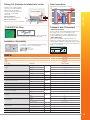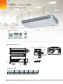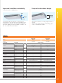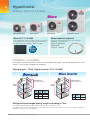
1
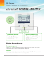
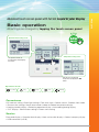
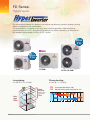
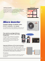
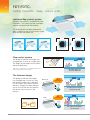
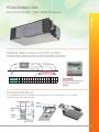
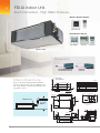
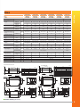
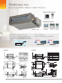
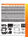
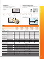
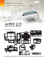
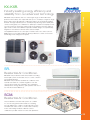
Back
Light
FD Series
Inverter Packaged Air Conditioners
MHIAA is proudly sponsoring
Monika’s Doggie Rescue
2
FD Series.
Inverter Packaged Air Conditioners.
change
setting by
button taps
only
Run / Stop
High power operation
Energy-saving operation
Maximum capacity
operation (Max 15 minutes)
• Increased compressor speed
• Increased air flow
• Changes set temperature at 28ºC in
cooling mode and 22ºC in heating mode,
25ºC in auto mode.
• Operation correction by outdoor
temperature
Main functions
Energy management
Peak cut timer • Automatic temperature set back • Weekly timer • Set ON/OFF timer by hour
• Set ON/OFF timer by clock • Fan only operation • Sleep timer
Comfort
Individual flap control • High power operation • External ventilation ON/OFF • Warm up operation
Automatic fan speed • Temperature increment setting by 0.5ºC
FD series Inverter Packaged Air Conditioners 2013
Basic operation
All settings are changed by tapping the touch screen panel
PRODUCTS
Advanced touch screen panel with full dot Liquid Crystal Display
Operation mode setting screen
Temperature setting screen
The operation mode can
be selected by simply tapping
this button.
You can select the desired
temperature by tapping the ▲▼
button.
Operation mode
Cooling
Dry
Auto
Fan
Heating
Convenience
LCD contrast setting • Back light setting • Filter clean sign • Control sound • Outdoor silent mode
• Summer time setting • Home leave mode • Indoor & outdoor temperature display
• Heating standby display • Defrosting operation display • Auto cooling/heating display
• ºC/ºF display • Administrator settings • Room name setting
Service
Error code display • Operation data display • Next service data display • Contact company display
• USB connection (mini-B)
3
4
FD Series.
Hyperinverter.
Our advanced technology has allowed us to achieve high efficiency, powerful heating and long
distance refrigerant piping specifications.
This feature permits installation of the units when a heating operation under temperature
conditions down to -20˚C is required. Design flexibility has been improved by an extension of
the refrigerant piping length to 100m (12.5 & 14.0kW).
Blue
Fin
Micro
5.0 & 6.0kW
Blue
Fin
7.1kW
10.0kW
12.5 & 14.0kW
Long piping
Strong heating
(in case of 12.5 & 14.0kW)
(in case of 7.1~14.0kW)
Height
difference
(Outdoor higher
than Indoor)
Piping
length
100m
FD series Inverter Packaged Air Conditioners 2013
-20C
-15C
: Heating operation down to -20C
: Nominal heating capacity maintained at -15C
Heating
-20C
30m
Cooling
-15C
-30
-20
+20C
-10
0
10
20
+43C
30
40
50
Micro Inverter
8.8
0
-15C
2C
50C
40C
Hyper Inverter
30C
20C
7C
10C
Micro Inverter
0C
4minutes
8minutes
Micro Inverter
Compact design of outdoor units
FDC100VN 10.0kW
Reduction in height by 22.3%
* Vector control:
To convert the current
wave to a smooth
sinusoidal waveform.
Size reduction and high efficiency
performance of the DC twin rotary
compressor
The
DC twin rotary compressor can operate
New model
DC rotary
compressor
at
speeds
as high as 120 rps to achieve the
required capacity. Vector control provides
perfect compressor control. Starting current
has reduced significantly and vibration has
been minimized.
Reduction in height by 22.3%
Reduction in volume by 44.1%
* Vector control:
To convert the current
wave to a smooth
sinusoidal waveform.
Height at 342mm
ø133mm
Height at 342mm
Our
single
fan micro
10.0kW condenser is one of the most
Reduction
in volume
by 44.1%
compact in the industry being only 845(h)x970(w)x370(d)
Height at 440 mm
rmer
pressor
Heating capacity (in case of 12.5kW)
(kW)
Temperature
of supply air can reach 40˚C 4 minutes after
18.0
nominal heating
starting upKeeping
under
low temperature
operation conditions
Hyper Inverter
capacity at -15C
14.5
nominal
(at
and can
14.0 both indoor and outdoor temperature of 2˚C)heating
capacity
reach 50˚C ≠≠≠≠≠≠8 minutes after that.
14.0kW
PRODUCTS
ameter of shell
5mm
Heating capacity
Heating capacity
Outside diameter of shell
ø185mm
ø133mm
Former
compressor
New model
DCFormer
rotary compressor
model
Current model
Improved efficiency of the heat exchanger
Re-designing the fins to a straight shape has reduced the
pressure loss of the air flow in the heat exchanger. A new
surface treatment on the fins has enhanced the frost resistance
capacity compared to former models. A high speed fan motor
has increased the airflow which allows cooling capacity to be
maintained even at high outdoor air temperatures.
Protection
Improved operation of the electronic expansion valve allows
for more reliable oil return and this assists to protect the
compressor.
Former model
Current model
5
6
FDT-FDTC.
Ceiling Cassette - 4way - Indoor units.
Individual flap control system
Individual flap control is available even after
installation. This means that the installation
area has become wider than before.
The outlet design has been perfected to
allow sufficient air flow that can reach a long
distance from the indoor unit.
Previous
Previous
Upper
position
Flap control system
The design of the heat exchanger has
changed from 2 parts to a single piece.
The height of the indoor unit has been
reduced significantly.
*RCH-E3 is not applicable to the Individual flap control
system and the Flap control system.
Previous
Upper
position
Current
Current
Current
Movable
range
Movable Lower
range
position
Upper
position
Lower
position
For person who is far
Movable
range
For person
whoindoor
is far unit
from the
from the indoor unit
Lower
position
The thinnest design
FDT125~140
The design of the heat exchanger
FDT125~140
has changed from 2 parts to 1 part,
the height of indoor unit is reduced.
DC fan motors are used to increase
efficiency. Weight has been reduced
FDT125~140
and as a result the unit has become
one of the most compact in the
industry.
FDT71
FDT71
Shape
of heat
heatexchanger
exchanger
Shape of
18%
18%
reduction!!
For person who is far
from the indoor unit
reduction!!
365mm
365mm
18%
reduction!!
298298
mm
mm
For both persons who are
For both persons who are
feeling
or cold
feeling
hot orhot
cold
365mm
For both persons who are
9%9%
298
reduction!!
reduction!!
feeling hot or cold
mm
270mm
270mm
Previous
Previous
Current
Current
FDT71
246
9% 246
mmmm
reduction!!
Shape of heat exchanger
Can Can
cool cool
both both
the kitchen
the kitchen
and the
andguests
the guests
270mm
Previous
Current
FD series Inverter Packaged Air Conditioners 2013
246
mm
Can cool both the kitchen
and the guests
FDUA Indoor Unit.
Duct Connected - High Static Pressure.
PRODUCTS
External static pressure (E.S.P.) control
Selecting the external static pressure setting the optimum air flow volume can be achieved.
The indoor unit will recognize the external static pressure setting and keep rated air volume.
New
FDUA
Duct
Duct
Longer Duct
Ceiling
Keep the same
air flow volume
Setting No.
1
E.S.P. (Pa)
10 20 30 40 50 60 70 80 90 100 110 120 130 140 150 160 170 180 200
2
3
4
5
6
7
8
9
10 11 12 13 14 15 16 17 18 19
E.S.P. button
External static pressure
can be set by E.S.P.
button.
Improved servicing
Improved servicing
Fan unit (impeller and motor) can be pulled out from the right side of the unit. Maintenance access is available
from both the right side and below the unit.
Pipe
Unit
Fan unit
Maintenance
hole
Service
space
7
FDUA Indoor Unit.
Duct Connected - High Static Pressure.
Wired Remote Control
RC-EX1A
Wireless Remote Control
RC-E5
RCH-E3
RCN-KIT3-E
Wired Remote Control
RC-EX1A
W
RC-E5
RCH-E3
FDUA71~160VF
Dimension
H 398
H 280
(1) Indoor units
Model FDUA71VF
65
39
Drain can be discharged upwards by 600mm
from the ceiling surface. It allows a piping layout
with a high degree of freedom depending on the
installation location.
FDUA71VF
Unit:mm
740 Duct dimension
Symbol
A
Gas piping
B Liquid piping
C1 Drain piping
Drain piping
C2
Gravity drainage
D Hole for wiring
E Suspension bolts
F
Inspection hole
185
41
600mm Drain Pump
200 Duct dimension
FDUA100/125/140/160VF
Return air duct
Drain hose piece
Accessory
Content
15.88 5 8"
Flare
9.52 3 8"
Flare
VP25 I.D.25,O.D.32
VP20 I.D.20,O.D.26
M10
450X450
Installed on site
Under 60
55
880 Duct dimension
55
100
C2
635
510
471
413
175
105
Max. drain lift
76
D
600 or less
295 325
15
43
Air supply duct
30
280
250
472
E
620
Note 1 The model name label
is attached on the lid
of the control box.
B
A
135
Suspension bolts pitch
Duct dimension
C1
69
58
67
or more
1300
Inspection
hole
Control box
less than
600mm
From bottom of unit
600
Flexible hose
FD series Inverter Packaged Air Conditioners 2013
Case 2
18
284
82
or more
18
28
Hanger plate for
suspension bolt
986 Suspension bolts pitch
950
170
8
467
30
FDUA
FDUA100VNVF
FDUA100VNXVF
FDUA125VNXVF
FDUA140VNXVF
FDUA71VF
FDUA100VF
FDUA100VF
FDUA125VF
FDUA140VF
FDUA160VF
Outdoor
FDC71VNX
FDC100VN
FDC100VNX
FDC125VNX
FDC140VNX
FDCA160VS
7.1 (3.2-8.0)
10 (4.0-11.2)
10 (4.0-11.2)
12.5 (5.0-14.0)
14.0 (5.0-14.5)
16.0 (7.0-20.0)
8.0 (3.6-9.0)
11.2 (4.0-12.5)
11.2 (4.0-12.5)
14.0 (4.0-17.0)
16.0 (4.0-18.0)
18.0 (7.6-22.4)
Heating H2
5.9
10.0
13.5
14.0
15.0
15.0
Cooling T1
2.22
3.05
2.85
3.83
4.44
5.02
2.22
2.87
2.74
3.68
4.41
4.96
3.19
Power supply
Outdoor Unit
Heating H1
Input
3 Phase 415V 50Hz
1 Phase 230V 50Hz
Cooling T1
Capacity
FDUA160VSVF
kW
kW
Heating H1
EER
Cooling T1
3.20
3.28
3.51
3.26
3.15
COP
Heating H1
3.60
3.90
4.09
3.80
3.63
3.63
Indoor
P-Hi:38 Hi:33
Me:29 Lo:25
P-Hi:43 Hi:42
Me:40 Lo:37
P-Hi:43 Hi:42
Me:40 Lo:37
P-Hi:45 Hi:43
Me:41 Lo:37
P-Hi:47 Hi:46
Me:43 Lo:40
P-Hi:49 Hi:48
Me:45 Lo:42
51
49
48
48
49
57
Sound pressure level (JIS
C9612)
dB(A)
Outdoor
Sound power level (JIS
C9612)
Airflow
Outdoor
dB(A)
66
70
70
70
72
74
Indoor
l/s
P-Hi: 400 Hi: 317
Me: 250 Lo: 167
P-Hi:650 Hi:600
Me:550 Lo:483
P-Hi:650 Hi:600
Me:550 Lo:483
P-Hi:717 Hi:650
Me:600 Lo:500
P-Hi:850 Hi:800
Me:700 Lo:600
P-Hi:850 Hi:800
Me:700 Lo:600
280 x 950 x 635
398 x 1150 x 650
398 x 1150 x 650
398 x 1150 x 650
398 x 1150 x 650
398 x 1150 x 650
750 x 880(+88)
x 340
845 x 970 x 370
1300 x 970 x 370
1300 x 970 x 370
1300 x 970 x 370
1505 x 970 x 370
External Static Pressure
Pa
200
Indoor
External dimensions
(HXWXD)
mm
Outdoor
Indoor
Net weight
kg
Outdoor
Liquid line
Refrigerant piping
mm
Gas line
34
52
52
52
52
52
60
81
105
105
105
140
Ø9.52
Ø9.52
Ø9.52
Ø9.52
Ø9.52
Ø12.7
Ø15.88
Ø15.88
Ø15.88
Ø15.88
Ø15.88
Ø22.22
Connection method
Refrigerant R410A
Flare Connection
kg
2.95
3.8
4.5
4.5
4.5
7.2
Pre charged to pipe
length
m
30
30
30
30
30
30
50
100
100
100
70
m
50
Supply Air Connection
mm
170 x 880
Return Air Connection
mm
200 x 740
348 x 898
348 x 898
Controller
RC-E5, RC-EX1A or RCN-KIT3-E
348
898 Duct dimension
181
472
Inspection
hole
C1
69
B
A
M10
450X450
12.7 1 2"
22.22 7 8"
40
295 325
G
Under 60
or less
15
215
Air supply duct
111
898 Duct dimension
182
181 192
Flare
Brazing
From bottom of unit
C2
650
Notes 1) The model name label is attached on the lid
of the control box.
(2) Connect the piping with local pipe by using the pipe of the
attachment. Liquid side and Gas side
61
74
E
24
Duct dimension
VP25 I.D.25,O.D.32
Control box
150
506
Case 2
17.5
284
86
VP25 I.D.25,O.D.32
100
1150
C2
111
Drain piping
Drain piping
Gravity drainage
Hole for wiring
Suspension bolts
Inspection hole
Connecting position of the local pipe. liquid side
Connecting position of the local pipe. gas side
600
1500
40
Flare
or more
100
or less
600
215
D
650
531
498
458
398
370
248
172
15
Max. drain lift
40
348
150
Air supply duct
Suspension bolts pitch
Hanger plate for
suspension bolt
61
74
295 325
17.5
600
650
B
A
E
24
Inspection
hole
C1
69
Under 60
Duct dimension
Suspension bolts pitch
472
Control box
9.52 3 8"
D
E
F
G
H
Drain hose piece
Accessory
28
From bottom of unit
or more
Case 2
17.5
284
82
28
1150
Flare
Connecting position of the attached
connecting pipe liquid side
or more
Return air duct
1185
Suspension bolts pitch
Suspension bolts pitch
15.88 5 8"
B
C2
Installed on site
or more
1185
Connecting position of the attached
connecting pipe gas side
Max. drain lift
M10
450X450
A
C1
VP25 I.D.25,O.D.32
Installed on site
17.5
181
1500
898 Duct dimension
H
D
650
531
498
458
40
398
370
248
172
Drain hose piece
Accessory
15.88 5 8"
Flare
9.52 3 8"
Flare
VP25 I.D.25,O.D.32
111
Content
600
24
Return air duct
Content
Symbol
26
Symbol
A
Gas piping
B
Liquid piping
C1
Drain piping
Drain
piping
C2
Gravity drainage
D
Hole for wiring
E
Suspension bolts
F
Inspection hole
Duct dimension
Unit:mm
181
Unit:mm
Model FDUA160VF
24
898 Duct dimension
26
111
348
Duct dimension
Models FDUA100VF, 125VF, 140VF
348
Brazed
Quantity
Maxium Pipe Length
Hanger plate for
suspension bolt
PRODUCTS
FDUA71VNXVF
Indoor
506
Note 1 The model name label is attached
on the lid of the control box.
Outline drawing (Unit:mm)
9
Model FDUM50VF
Models FDUM60,71VF
FDUM Indoor Unit.
10
Duct Connected - Medium Static Pressure.
Wired Remote Control
RC-EX1A
Wireless Remote Control
RC-E5
RCH-E3
RCN-KIT3-E
Wired Remote Control
RC-EX1A
FDUM50 ~ 140VF
RC-E5
Thin design
Drain can be discharged upwards by 600mm from
the ceiling surface. It allows a piping layout with a
high degree of freedom depending on the installation
location.
The height of all FDUM models is only 280mm.
70mm less
less than
600mm
19mm less
H 350
H 299
H 280
H 280
FDUM100/125/140VF
FDUM60VF
Model FDUM60VF
55
C2
76
Suspension bolts pitch
18
284
81
Control box
635
510
471
413
30
M
FD series Inverter Packaged Air Conditioners 2013
4
4
Holes for
tapping screws
139
58
67
E
Air supply duct
Hole
295 325
D
55
467
262
170
880 Duct dimension
55
F
G
View M
30
Max. drain lift
30
152
124
or less
90
2" Flare
6.35 1 4" Flare
VP20 standard:I.D.20, O.D.26 or VP25 Used
with attached socket:I.D.25, O.D.34 Note 2
Drain piping
VP20 standard:I.D.20, O.D.26 or VP25
C2
Gravity drainage Used with attached socket:I.D.25, O.D.34
D
Hole for wiring
E
M10
Suspension bolts
Outside air opening
F
150 Knock out
for ducting
Air outlet opening
125 Knock out
G for ducting
H
450X450
Inspection hole
Notes 1 The model name label is attached on the lid of the control box.
2 Prepare the connecting socket VP20 or VP25 on site.
B
A
76
G
C1
69
G
600
472
F
135
139
F
170
Drain piping
113
4
4
Holes for
tapping screws
15
262
C1
4
4
Holes for
tapping screws
28
950
Liquid piping
105
31
170
31
986
18
Hanger plate for
suspension bolt
Content
12.7 1
B
90
635
510
471
413
170
30
175
Duct dimension
41
200
39
Return air duct
14
4
Holes for
tapping screw
50
15
D
680 Duct dimension
152
Hole
295 325
Drain hose piece
Accessory
Installed on site
450X450
View M
50
43
Air supply duct
Symbol
A
Gas piping
65
46
200
125 Knock out
170
Max. drain lift
E
150 Knock out
Suspension bolts pitch
135
B
A
600 or less
472
69
4
4
Holes for
tapping screws
124
C1
860 Duct dimension
4 200=800
M10
Notes 1 The model name label is attached on the lid of
the control box.
2 Prepare the connecting socket VP20 or VP25 on site.
18
284
81
28
750
58
67
170
Hole for wiring
Suspension bolts
Outside air opening
for ducting
Air outlet opening
for ducting
Inspection hole
H
Suspension bolts pitch
G
Duct dimension
Suspension bolts pitch
D
E
F
Control box
55
Drain piping
Gravity drainage
G
F
M
C2
105
786
18
Drain piping
65
46
43
Return air duct
12
4
Holes for
tapping screw
C1
12.7 1 2" Flare
6.35 1 4" Flare
VP20 standard:I.D.20, O.D.26
or VP25 Used with attached
socket:I.D.25, O.D.34 Note 2
VP20 standard:I.D.20, O.D.26
or VP25 Used with attached
socket:I.D.25, O.D.34
280
250
175
39
31
Installed on site
Gas piping
Liquid piping
Duct dimension
170
Drain hose piece
Accessory
Content
A
B
170
65
46
113
660 Duct dimension
200 200 200
31
41
200
Duct dimension
Symbol
Hanger plate for
suspension bolt
FDUM50/60/71VF
280
250
FDUM50VF
Model FDUM50VF
65
46
RCH-E3
600mm Drain Pump
Flexible hose
W
C2
467
Outline drawing (Unit:mm)
Model FDUM50VF
FDUM
FDUM50ZJXVF
Power supply
FDUM71VNXVF
FDUM100VNVF
FDUM125VNXVF
FDUM140VNXVF
FDUM50VF
FDUM60VF
FDUM71VF
FDUM100VF
FDUM125VF
FDUM140VF
SRC50ZJX-S
SRC60ZJX-S
FDC71VNX
FDC100VN
FDC125VNX
FDC140VNX
5.0 (2.2-5.6)
5.6 (2.8-6.3)
7.1 (3.2-8.0)
10.0 (4.0-11.2)
12.5 (5.0-14.0)
14.0 (5.0-14.5)
5.4 (0.6-6.3)
6.7 (0.6-7.1)
8.0 (3.6-9.0)
11.2 (4.0-12.5)
14.0 (4.0-17.0)
16.0 (4.0-18.0)
Outdoor Unit
1 Phase 230V 50Hz
Cooling T1
Capacity
Heating H1
Input
kW
Heating H2
4.3
4.9
7.0
11.4
13.7
14.3
Cooling T1
1.56
1.75
2.20
2.92
3.60
4.48
kW
Heating H1
1.70
2.00
2.20
3.20
3.90
4.54
3.21
3.20
3.23
3.42
3.47
3.15
EER
Cooling T1
COP
Heating H1
3.18
3.35
3.64
3.50
3.59
3.63
Indoor
P-Hi:37 Hi:32
Me:29 Lo:26
P-Hi:36 Hi:31
Me:28 Lo:25
P-Hi:38 Hi:33
Me:29 Lo:25
P-Hi:44 Hi:38
Me:36 Lo:30
P-Hi:45 Hi:40
Me:34 Lo:29
P-Hi:47 Hi:40
Me:35 Lo:30
50
54
51
49
50
49
Sound pressure level (JIS
C9612)
dB
(A)
Outdoor
Sound power level
(JIS C9612)
Outdoor
dB(A)
63
64
66
70
70
72
Indoor
l/s
P-Hi: 217 Hi: 167
Me: 150 Lo: 133
P-Hi:333 Hi:250
Me:217 Lo:167
P-Hi: 400 Hi: 316
Me: 250 Lo: 166
P-Hi:600 Hi:467
Me:417 Lo:317
P-Hi:650 Hi:533
Me:433 Lo:333
P-Hi:800 Hi:583
Me:467 Lo:367
Airflow
External Static Pressure
Pa
Indoor
External dimensions
(HXWXD)
Indoor
100@333 l/s
100@400 l/s
100@600 l/s
100@650 l/s
100@800 l/s
280 x 950 x 635
280 x 950 x 635
280 x 1370 x 740
280 x 1370 x 740
280 x 1370 x 740
640 x 800
(+71) x 290
640 x 800
(+71) x 290
750 x 880
(+88) x 340
845 x 970 x 370
1300 x 970 x 370
1300 x 970 x 370
kg
Outdoor
Liquid line
Refrigerant piping
100@217 l/s
280 x 750 x 635
mm
Outdoor
Net weight
mm
Gas line
29
34
34
54
54
54
45
45
60
81
105
105
Ø6.35
Ø6.35
Ø9.52
Ø9.52
Ø9.52
Ø9.52
Ø12.7
Ø12.7
Ø15.88
Ø15.88
Ø15.88
Ø15.88
Connection method
Refrigerant R410A
PRODUCTS
Indoor
Outdoor
FDUM60ZJXVF
Flare Connection
Quantity
kg
1.5
1.5
2.95
3.8
4.5
4.5
Pre charged to
pipe length
m
15
15
30
30
30
30
Maxium Pipe Length
m
30
30
50
50
100
100
Supply Air Connection
mm
170 x 680
170 x 880
170 x 880
170 x 1200
170 x 1200
170 x 1200
Return Air Connection
mm
200 x 660
200 x 860
200 x 860
235 x 1280
235 x 1280
235 x 1280
Controller
RC-E5, RC-EX1A or RCN-KIT3-E
FDUM71VF
FDUM100VF, 125VF, 140VF
Models FDUM100VF, 125VF, 140VF
1404
55
124
B
A
G
71
170
C1
Hole
180
104
D
1200 Duct dimension
104
C2
Max. drain lift
92
15
Air supply duct
295 325
30
600 or less
280
250
184.5
134.5
E
43
467
18
284
81
59
69
M
C2
Hole for wiring
Suspension bolts
M10
Outside air opening
150 Knock out
for ducting
Air outlet opening
G
125 Knock out
for ducting
450X450
H Inspection hole
Notes 1 The model name label is attached on the lid of
the control box.
4
4 2 Prepare the connecting socket VP20 or VP25 on site.
4
4
Holes for
Holes for
tapping screws
152 285
tapping screws
Control box
Suspension bolts pitch
30
Duct dimension
635
510
471
413
170
Drain piping
Drain piping
Gravity drainage
F
F
530
113
G
View M
90
C1
15.88 5 8" Flare
9.52 3 8" Flare
VP20 standard:I.D.20, O.D.26
or VP25 Used with attached
socket:I.D.25, O.D.34 Note 2
VP20 standard:I.D.20, O.D.26
or VP25 Used with attached
socket:I.D.25, O.D.34
D
E
Return air duct
1368
Content
Gas piping
Liquid piping
113
24.5
205
24.5
14
4
Holes for
tapping screw
18
Hanger plate for
suspension bolt
139
30
or less
880 Duct dimension
C2
76
50
D
F
105
295 325
15
Air supply duct
Hole
Max. drain lift
E
43
262
4
4
Holes for
tapping screws
170
600
472
135
Suspension bolts pitch
152
124
B
A
58
67
Duct dimension
C1
69
G
170
Installed on site
45
4
4
Holes for
tapping screws
Drain hose piece
Accessory
28
18
284
81
28
950
Suspension bolts pitch
Suspension bolts pitch
A
B
64
100
139
Air outlet opening
125 Knock out
for ducting
H
450X450
Inspection hole
Notes 1 The model name label is attached on the lid of the control box.
2 Prepare the connecting socket VP20 or VP25 on site.
Control box
55
D
E
1280 Duct dimension
4 280=1120
280
G
F
M
C1
C2
Symbol
64
100
170
986
18
Hanger plate for
suspension bolt
9.52 3 8" Flare
VP20 standard:I.D.20, O.D.26 or VP25 Used
Drain piping
with attached socket:I.D.25, O.D.34 Note 2
Drain piping
VP20 standard:I.D.20, O.D.26 or VP25
Gravity drainage Used with attached socket:I.D.25, O.D.34
Hole for wiring
M10
Suspension bolts
Outside air opening
150 Knock out
for ducting
F
Return air duct
14
4
Holes for
tapping screw
Liquid piping
175
39
31
170
Installed on site
Flare
235
Drain hose piece
Accessory
Duct dimension
B
Content
15.88 5 8"
23.5
Symbol
A
Gas piping
65
46
21.5
860 Duct dimension
4 200=800
200
31
41
200
65
46
280
250
Duct dimension
Model FDUM71VF
F
G
View M
90
738
635
468
405
170
30
467
11
FDT - Indoor Unit.
12
Ceiling Cassette-4way.
Remote control (Option)
Remote control (Option)
Remote
Wired
Wired
control (Option)
FDT60 ~ 140VF
Wireless
Wireless
Wired
FDTC50VF
RC-EX1A
RC-EX1A
RC-E5
RC-EX1A
RC-E5
RCH-E3
RCN-T-36W-E
RCH-E3
RCH-E3
RC-E5 RCN-T-36W-E
RCN-TC-24W-ER
Wireless
Outline drawing (Unit:mm)
Model FDT 60,71VF
Model 100,125,140VF
H
G
H
G
H
H
H
H
H
H
C
B A
C
F
F
B A
H
H
D
D
G
G
FD series Inverter Packaged Air Conditioners 2013
Infrared control option
Detachable covers at each corner allows
for easy alignment and balance.
The panel does not need to
be removed. Installation time
is reduced.
For wireless control simply insert the infrared receiver
kit on the corner.
PRODUCTS
Installation
wireless
remote
control
wireless
remote
control
RCN-T-36W-E
RCN-T-36W-E
wireless remote
remote control
control
wireless
RCN-T-36W-E
RCN-T-36W-E
Easy checking of drain pan
700mm Drain Pump
To check the drain pan simply remove the corner lid.
Drain can be discharged upwards by Flexible
700mm
from
Flexible
hose the
hose
ceiling surface. The 260mm flexible hose is supplied as
standard equipment.
thanthan
Flexiblehose
hoselessless
Flexible
700mm
700mm
lessthan
than
less
700mm
700mm
FDT
Indoor
Outdoor
Power supply
FDT100VNVF
FDT125VNXVF
FDT140VNXVF
FDT71VF
FDT100VF
FDT125VF
FDT140VF
SRC60ZJX-S
FDC71VNX
FDC100VN
FDC125VNX
FDC140VNX
5.6 (2.8-6.3)
7.1 (3.2-8.0)
10.0 (4.0-11.2)
12.5 (5.0-14.0)
14.0 (5.0-16.0)
6.7 (3.1-7.1)
8.0 (3.6-9.0)
11.2 (4.0-12.5)
14.0 (4.0-17.0)
16.0 (4.0-18.0)
5.29
7.2
N/A
15.6
16
1.52
2.04
2.76
3.28
4.19
1.70
1.94
2.74
3.43
4.2
3.34
1 Phase 230V 50Hz
Heating H1
kW
Heating H2
Input
FDT71VNXVF
FDT60VF
Indoor Unit
Cooling T1
Capacity
FDT60ZJXVF
Cooling T1
Heating H1
kW
EER
Cooling T1
3.68
3.48
3.62
3.81
COP
Heating H1
3.94
4.12
4.09
4.08
3.81
P-Hi:46 Hi:33
Me:31 Lo:30
P-Hi:46 Hi:35
Me:33 Lo:31
P-Hi:51 Hi:40
Me:37 Lo:35
P-Hi:51 Hi:42
Me:40 Lo:37
P-Hi:51 Hi:43
Me:41 Lo:38
54
51
49
50
52
dB(A)
64
66
70
70
72
l/s
P-Hi: 466 Hi: 300
Me: 266 Lo: 233
P-Hi: 466 Hi: 350
Me: 316 Lo: 283
P-Hi: 616 Hi: 450
Me: 400 Lo: 333
P-Hi: 616 Hi: 500
Me: 450 Lo: 383
P-Hi: 616 Hi: 500
Me: 450 Lo: 383
Sound pressure level
(JIS C9612)
Indoor
Sound power level (JIS
C9612)
Outdoor
Airflow
Indoor
Panel
External dimensions
(HXWXD)
Net weight
T-PSA-3BW-E
(35 x 950 x 950)
mm
Indoor
Outdoor
Indoor
Outdoor
Liquid line
Refrigerant piping
dB (A)
Outdoor
Gas line
mm
kg
mm
246 x 840 x 840
640 x 800(+71) x 290
298 x 840 x 840
750 x 880(+88) x 340
845 x 970 x 370
Unit 24 Panel 5.5
45
Unit 27 Panel 5.5
60
81
Refrigerant R410A
Maxium Pipe Length
Controller
Pre charged to pipe length
105
Ø6.35
Ø9.52
Ø12.7
Ø15.88
Connection method
Quantity
1300 x 970 x 370
Flare connection
kg
1.5
m
15
m
30
2.95
3.8
4.5
30
50
100
RC-E5, RC-EX1A or RCN-T-36W-E
13
FDTC - Indoor Unit.
14
Ceiling Cassette-4way Compact 600x600mm
Remote control (Option)
Remote control (Option)
Remote
control (Option)
Wireless
Wired
Wireless
Wired
Wired
Wireless
FDTC50VF
FDTC50VF
FDTC50VF
RC-EX1A
RC-EX1A
RC-EX1A
RC-E5
RC-E5
RC-E5 RCH-E3
RCN-TC-24W-ER
RCH-E3
RCN-TC-24W-ER
RCH-E3
RCN-TC-24W-ER
Outline drawing (Unit:mm)
G
G
G
D
A B
C F
G
FD series Inverter Packaged Air Conditioners 2013
Taking OA (Outside air intake) into inside
Ceiling OA surface
OA
surface
Ceiling OA
surface
Spacer
Panel
OA Panel
OA
Panel
Joint Duct
Ceiling OAJoint Duct
“CLEARER”Air Flow
35dB
(dB)
35
36
34
35
35dB
33
34
32
33
Joint Duct
34
34
33
33
32
(dB)
3632
29
30
28
29
30
3430
3329
32
28
5dB
3127
Down
5dB
30
26
Down
29
30dB29
30dB28
26
25 5dB
Previous New
Previous
New
New
(Cooling/Heating)
(Cooling/Heating)
(Cooling)
27
32dB
30dB
Down
28
3dB
Down
Down
Down
27
25
Previous
26
(Cooling/Heating)
Previous
25
(Cooling/Heating)
3dB
Down
3dB
Down
3dB
32dB
Down
3dB
30dB
32dB
30dB Down
32dB
5dB
32dB
5dB
35dB31
3531
31
32
300mm
30
31
35dB
35
35dB
35
(dB)
36
27
28
26
300mm
27
Joint Duct
Joint Duct
25
26
OA
Panel
36
(dB)
36
25
Panel
surface
(dB)
Sound Pressure
level in the Lo mode
(Cooling)
New
(Cooling)
Previous
(Cooling/Heating)
(Heating)
New
(Heating)
New
New
(Cooling)
(Heating)
New
(Heating)
Compact and Convenient
New shape & angled louver redirects the air current
away from the ceiling, to reduce ceiling stains
Installation Workability
For wireless control simply insert the infrared
receiver kit onwireless
a corner of the panel
New
(Heating)
• 600mm Drain Pump
Drain can be discharged upward by 600 mm from
the ceiling surface close to the indoor unit.
It allows a piping layout with a high degree of
freedom depending on the installation location.
• 600 x 600 ceiling
Indoor unit size (W:570 x D:570) brings easy
installation for 600 x 600 ceiling and Panel size
(700 x 700) is suitable for 600 x 600 ceiling. Height
is one of the industry’s lowest level at 248mm and
Flexible hose
weight is only 16.5kg.
Flexible hose
248mm
remote
wirelesscontrol
248mm
RCN-TC-24W-ER
remote control wireless
wireless
wireless
remote
control
RCN-TC-24W-ER
remote remote
control control
New
(Cooling)
PRODUCTS
OA Spacer TC-OAS-E (option)
Joint Duct TC-OAD-E (option)
Utilizing OA spacer which
Indoor Unit FDTC
comes as optional equipment,
Indoor Unit FDTC
outside air can be taken
Indoor Unit FDTC
into inside.
Indoor Unit FDTC
Using 1 joint duct:
Indoor Unit FDTC
OA
3
300mm
OA comes up to 1.3m /min. OA
Spacer
300mm
Spacer
OA
Using 2 joint ducts: Spacer
Ceiling OA 300mm
OA 2.6m3/min.
OA
OA comes from 1.3 to
Ceiling surface
OA
OA
Spacer
Quiet operation
600mm
Flexible hose
Flexible hose
600mm
Flexible hose
600mm
248mm
248mm
600mm
600mm
248mm
RCN-TC-24W-ER
RCN-TC-24W-ER
RCN-TC-24W-ER
FDTC
FDTC50ZJXVF
Indoor
FDTC50VF
Outdoor
Power supply
SRC50ZJX-S
Outdoor Unit
1 Phase 230V 50Hz
Cooling T1
Capacity
Heating H1
5.0(1.1-5.6)
kW
Heating H2
Input
Cooling T1
Heating H1
EER
Cooling T1
COP
Heating H1
Sound pressure level (JIS C9612)
Indoor
Outdoor
Sound power level (JIS C9612)
Outdoor
Airflow
Panel
External dimensions (HXWXD)
Net weight
5.10
kW
Maxium Pipe Length
Controller
1.45
3.20
3.72
dB (A)
P-Hi:47 Hi:42 Me:36 Lo:32
54
63
Indoor
l/s
P-Hi: 225 Hi: 191 Me: 150 Lo: 133
TC-PSA-25W-E
mm
35 x 700 x 700
Indoor
Outdoor
Indoor
Outdoor
Gas line
mm
kg
mm
Connection method
Refrigerant R410A
1.56
dB(A)
Liquid line
Refrigerant piping
5.4 (0.6-6.3)
248 x 570 x 570
640 x 800(+71) x 290
Unit 15 Panel 3.5
45
Ø6.35
Ø12.7
Flare connection
Quantity
kg
1.5
Pre charged to pipe length
m
15
m
30
RC-E5, RC-EX1A or RCN-TC-24W-ER
VF model may be supplied in lieu.
15
16
FDEN - Indoor Unit.
Ceiling Suspended.
FDEN100/125VF
FDEN 100/125VF
Remote
control (Option)
Remote
control (Option)
Remote
control
(Option)
Wireless
Wireless
Wireless
Wired
Wired
Wired
FDTC50VF
RCH-E3
RC-EX1ARC-EX1A
RC-E5 RC-E5
RC-EX1A
RC-E5
FDTC50VF
Remote control (Option)
RCN-TC-24W-ER
RCH-E3
RCN-E1R
RCH-E3
RCN-TC-24W-ER
Wireless
Wired
Outline drawing (Unit:mm)
290(Suspension bolts pitch)
24
5
135
b
40
e
d
173
RC-EX1A
Holes for suspension bolts
(M8 to M10x4pcs.Not included)
410
145
68
RC-E5
52
53
109
690
195
235
271
Indication board
110
135
Drain hole
connection(1)
(VP20(I.D.20))
Dimension Table
model
FDEN100~125
a
b
c
d
e
1572
1540
1620
255
250
FD series Inverter Packaged Air Conditioners 2013
53
10
308
Note(1) The slope of drain piping
inside the unit is able
to take incline of 10mm.
75 Liquid piping
Gas piping
Air inlet grille
Liquid piping
40
Air outlet
Drain hole
connection(1)
(VP20(I.D.20))
76
RCH-E3 RCN-E1R
Gas piping
c
Space for installation and service
100
or more
300 or more
a (Suspension bolts pitch)
24
150
or more
Obstacles
Drain hole
connection(1)
(VP20 (I.D.20))
5
or more
Improved installation workability
Compact and modern design
Increased freedom of a piping layout
Height
Height
250mm
250mm
Right
Right
PRODUCTS
Up
Up
Rear
The refrigerant pipe from the unit can be arranged in
three directions, rear, right and up. The drain pipe can be
arranged in two directions, left and right. This will allow a
free layout of piping for various installation conditions. The
unit can only be serviced from below.
All models fit compactly on ceiling. (Height-210mm or
250mm).
Plain, modern design featuring rounded edges gives
room a comfortable atmosphere.
FDEN
FDEN100VNVF
FDEN125VNXVF
Indoor
FDEN100VF
FDEN125VF
Outdoor
FDC100VN
FDC125VNX
Power supply
Outdoor Unit
1 Phase 230V 50Hz
Cooling T1
Capacity
Heating H1
kW
Heating H2
Input
Cooling T1
Heating H1
kW
10 (4.0-11.2)
12.5 (5.0-14.0)
11.2 (4.0-12.5)
14.0 (4.0-17.0)
NA
15.0
2.85
3.86
2.97
3.77
EER
Cooling T1
3.51
3.23
COP
Heating H1
3.77
3.71
Energy Label
Sound pressure level (JIS C9612)
Sound power level (JIS C9612)
Airflow
External dimensions (HXWXD)
Net weight
Cooling T1
Heating H1
Indoor
Outdoor
Outdoor
Indoor
Indoor
Outdoor
Indoor
Outdoor
Liquid line
Refrigerant piping
Gas line
2
1
2.5
2
P-Hi:46 Hi:44 Me:41 Lo:39
P-Hi:50 Hi:46 Me:44 Lo:43
49
50
dB(A)
70
70
l/s
P-Hi:466 Hi:433 Me:383 Lo:350
Stars
dB (A)
mm
kg
845 x 970 x 370
Maxium Pipe Length
Controller
1300 x 970 x 370
49
81
105
Ø9.52
mm
Ø15.88
Connection method
Refrigerant R410A
P-Hi:533 Hi:483 Me:433 Lo:383
250 x 1620 x 690
Flare Connection
Quantity
kg
Pre charged to pipe length
m
m
3.8
4.5
30
50
100
RC-E5, RC-EX1A or RCN-E-E
17
18
Hyperinverter.
Outdoor Unit 5.0-14.0kW.
Micro
SRC50/60ZJX-S
FDC100VN
FDC71VNX
FDC125/140VNX
Blue Fin 7.1-14.0kW
Base heater kit (option)
Due to application of blue coated fins (KS101) for the heat
exchanger of the new outdoor unit, corrosion resistance
has been improved compared to previous models.
This kit is recommended for use in areas where the
temperature drops below 0˚C.
Blue
Fin
Blue
Fin
CW-H-E applied for
FDC100VN
FDC125~140VNX
Installation workability.
Enhanced installation workability thanks to the extended pipe length – one of the longest levels in the
industry. Units are pre-charged with refrigerant.
Piping length – 100m (Hyper Inverter 12.5~14.0kW)
Micro Inverter
Height difference
Height difference
(Outdoor higher than Indoor)
(Outdoor higher than Indoor)
Piping
length
Piping
length
Piping
length
Height
difference
5~6
30m
20m
7.1
50m
30m
12.5~14
100m
30m
kW
kW
10
Piping
length
Height
difference
50m
30m
Refrigerant precharged piping length extending to 30m
Precharged refrigerant piping length extends up to 30m. (5.0 & 6.0kW up to 15m)
This eliminates the need to add refrigerant on site, which sets it free from the trouble of excessive or insufficient charging of
refrigerant, and allows smooth installation.
FD series Inverter Packaged Air Conditioners 2013
High efficiency.
Increase of heat transfer efficiency
Pressure caused by air flow in the indoor unit is reduced by
making the air outlet larger. The reduction of pressure reduces
the load on the fan motor so efficiency increases.
Heat transfer efficiency has improved by using high efficiency
piping and by the redesign of the heat exchanger from 2 to 1
piece.
PRODUCTS
Reduction of air flow pressure loss
Convenience.
A dry contact is fitted to each indoor unit which is used
when a signal output is required.
CnT
CnT terminal
XR2
XR3
XR1
output1 (run)
XR2
output2 (heat)
output3 (comp on)
XR3
XR4
XR4
XR5
Power
source
common
XR1
output4 (alarm)
in put
XR5
XR1~5 : approx. DC12v
Monitoring Function
Condensers are fitted with RS232C so you can connect
directly to your PC for monitoring. MHI’s service software
(Mente PC) makes service simpler.
Remote control RC-E5
The new remote control for all indoor units. Non-polar
2 core wiring is used. Installation is easier.
Previous
3-core
Current
2-core
All models employ R410A with RoHS* directive.
Employment of lead free solder
Adapt to RoHS
Employment of R410A refrigerant
All models of the FD inverter series use refrigerant R410A
characterized by an ozone depletion coefficient of 0.
Pressure caused by air flow in the indoor unit is reduced by
making the air outlet larger. The reduction of pressure reduces
the load on the fan motor so efficiency increases.
*”RoHS” is the abbreviation of the new European standard, which
means Restriction of Hazardous Substances.
19
20
SUPERLINK-
Control System.
KX6 series
SC-SL1N-E
RAC series
(SRK/SRF-ZJX-S)
SC-BIKN-E
SC-ADNA-E
SC-SL2NA-E
SC-ADNA-E
SC-ADNA-E
Central Control
SC-SL1N-E
SC-SL2NA-E
SC-SL3N-AE/BE
Start/stop control of up to 16 indoor units is
possible either individually or collectively. With
simple operations, you can effect centralised
control.
Centralised control of up to 64 indoor units.
Allows connection with a weekly timer without
using any interface.
Easy operation through the large color LCD
and touch panel. Up to 128 indoor units can be
controlled, when three SUPERLINK-II systems
are connected.
PC windows central control
SC-WGWNA-A/B
(SC-WGWNA-B has electric power calculation function)
BMS interface unit
SC-BGWN-A/B
(LonWorks gateway)
Up to 96 cells (some cells can have two or
more indoor units and total number of indoor
units can be up to 128 units) are controlled
centrally from a BMS.
Up to 96 indoor units (48 indoor unit x 2) are
linked as an open network. Centrally
controlled through LonWorks.
(SC-WGWN-B has electric power calculation function)
Up to 96 cells (some cells can have two or
more indoor units and total number of
indoor units can be up to 128 units) are
controlled from the Internet.
Additional engineering service cost is required.
Please consult your dealer when using this central
control.
FD series Inverter Packaged Air Conditioners 2013
SC-LGWN-A
(BACnet gateway)
Additional engineering service cost is required. In case
of SC-BGWN-B, communication test by qualified
person regarding electric cost calculation function is
required before commissioning. Please consult your
dealer when using this gateway.
Additional engineering service cost is required.
Please consult your dealer when using this gateway.
SUPERLINK E BOARD (SC-ADNA-E)
(1) Functions
(a) Transmits the settings from the network option to the indoor units.
(b) Returns the priority indoor unit data in response to a data request from the network option.
(c) Inspects the error status of connected indoor units and transmits the inspection codes to the network option.
(d) A maximum of 16 units can be controlled (if in the same operation mode).
(2) Wiring connection diagram
Blue
A
Run
Abnormal
SL E board
A
Blue
B
LED3
LED2
X
White
Y
Y
ON
SW3
OFF
SW2
SW1
Connected to the terminals for
Superlink signal lines
MVVS 0.75 - 1.25mm2
B
Black
X
Connected to the remote controller terminals (no
polarity) (the length should be 600 m or shorter)
200 m or shorter
0.5 mm2 x 2 cores
300 m or shorter
0.75 mm2 x 2 cores
400 m or shorter
1.25 mm2 x 2 cores
600 m or shorter
2.0 mm2 x 2 cores
Network address setting switches
[000]-(127)
Master/Sub
address
Basic Connections
Plural Controls by Multiple Remote Controls. Mixture of Multiple Units
Outdoor unit
Outdoor unit
Internal/external Crossing
Internal/external Crossing
Indoor unit
X Y
SL E Board
X Y
A B
Inside Inside Inside Inside
Remote control
X Y
SL E
Board
Network
options
Network A B
options
R
R
• Transmit the information of plural “Master” units to the network.
• Transmit the abnormalities of the “Slave” units to the network.
Setting the plural “Master/Slave” units with the dip SW of the printed circuit board.
Setting the “Master/Slave” remote controls with the dip SW of the remote control board.
Plural Controls by Multiple Remote Controls. Mixture of Multiple Units
Outdoor unit
Outdoor unit
Internal/external Crossing
R
Inside Inside Inside
SL E
Board
R
Network
options
Without Remote Control
Outdoor unit
Internal/external Crossing
Inside Inside Inside Inside
SL E
Board
coNtroL sYstEM
This board is used when conducting control of the single package (wired remote control unit) 1-type series using a
network option (SC-SL1N-E, SC-SL2NA-E, etc).
R
R
Set up “000” to “127” using address switch on the SL E board.
Internal/external Crossing
Inside Inside
SL E
Board
Network
options
Set the SL E board dip SW
to “Master” SW3-1 ON.
The network option
SLA-1-E, SL1N-E is not
allowed (This will disturb
switching of the operation
mode)
Wireless Kit
Outdoor unit
Internal/external Crossing
Inside Inside
SL E
Board
Network
options
Wireless Kit
Wireless
remote control
(3) Metal box dimension
85
35
30
70
90
5
22.5
100
40
2-ø6
21
22
Control System.
Individual Control.
Remote Control line up
indoor unit
wired
remote control
RC-E5
all models
RCH-E3
wireless
indoor unit
FDT
FDTC
FDUM, FDU
FDEN
remote control
RCN-T-36W-E
RCN-TC-24W-ER
RCN-KIT3-E
RCN-E-E
Wired remote control with weekly timer (option)
RC-E5
Run hour metres to facilitate maintenance checking
RC-E5 stores operation data when an anomaly occurs and indicates the error on
the LCD. It also displays cumulative operation hours of the air conditioner and
compressor since commissioning.
The RC-E5 controller enables
extensive access to service
and maintenance technical
data combined with easy to
use functions and a clear
LCD display.
Weekly timer function as standard
RC-E5 provides (as a standard feature) a weekly timer, which allows
one-week operation schedules to be registered. A user can specify up to
four times a day to start/stop the air conditioner. (Temperature setting is also
possible with the timer).
Timer operation
Room temperature controlled
by the remote control sensor
The temperature sensor is housed in the top
section of the remote control unit. This
arrangement has improved the sensitivity of the
remote control unit’s sensor, which permits more
finely controlled air conditioning.
Changeable set temperature ranges
RC-E5 allows the upper and lower limits of a set temperature range to be
specified separately.
By adjusting a set temperature range, you can ensure energy saving air
conditioning by avoiding excessive cooling or heating.
Changeable range
Upper limit
20~30C(effective for heating operation)
Lower limit
18~26C(effective for non-heating operation)
Simple remote control (option)
RCH-E3 (wired)
Considering specialised usage in hotel rooms,
control buttons are limited only to minimum
required functions such as ON/OFF, mode,
temperature setting and fan speed. It is really
simple and easy to use.
RCH-E3 is not applicable to the Individual flap control
system and the Flap control system.
When RCH-E3 is used, the fan has 3 speed settings
(Hi-Me-Lo) only.
Up to 16 units
It can control up to 16 units individually, by pressing the AIR CON No. button.
AUTO restart
This function allows starting the air conditioner automatically when power supply
is restored after power failure or by turning on the power switch.
Wireless remote control (option)
Thermistor (option)
SC-THB-E3
For wireless control simply insert the infrared
receiver kit on a corner of the panel.
RCN-T-36W-E,
RCN-TC-24W-ER
RCN-KIT3-E
When wireless remote control is used, the fan has 3 speed settings (Hi-Me-Lo) only.
FD series Inverter Packaged Air Conditioners 2013
RCN-E-E
This sensor is used when individual remote control is
not required in each room and the system is under
central control. By installing sensors in strategic
locations through out the structure greater comfort
control is achieved. In many instances one additional
sensor is all that is required.
KX-KXR.
Industry leading energy efficiency and
reliability from our advanced technology.
PRODUCTS
Mitsubishi Heavy Industries offers one of the largest ranges of VRF multi inverter
products in the industry. The compact M series (11.2 to 15.5kW) is a single fan, single
phase outdoor that is providing air conditioning solutions all over Australia and New
Zealand. The larger side blow (22.4 to 33.5kW) and top discharge (40 to 68kW) units
can be used singularly or in combination to deliver up to 136kW of heat pump or heat
recovery technology and energy saving in high rise and mid rise structures. With 16
types of indoor units and 78 different capacities available designs are only limited by
imagination. Our eSolution software makes selection simple.
The SuperlinkII network can control up to 128 indoor units via a central control or
BMS interface such as Web or BACnet gateways. Mente PC can be connected for
fault finding and recording test run reports.
VRF inverter multi-system
Air-Conditioners
SR.
Residential Air Conditioner.
Mitsubishi Heavy Industries wall mounted and floor standing
inverter split systems are the ideal choice to control comfort in
any residential situation.
Mitsubishi Heavy Industries residential air conditioners have
received rave reviews in consumer magazines here and
overseas when tested and compared to the competitions
similar products. Energy efficiency, quite operation and ease of
use were the standout differences.
SCM.
Residential Air Conditioner.
These residential use inverter multi system can condition
2 to 6 rooms using either wall mounted, floor standing,
low static bulkhead or compact cassette type indoor units.
The SCM series offers a total of 7 outdoor units and many
indoor units making hundreds of different comfort
combinations possible. Perfect for homes and apartments.
23
Before starting use
Heating performance
Refrigerant leakage
The heating performance values (kW) described in catalog are the values
obtained by operating at an outdoor temperature of 7C and indoor temperature
of 20C as set forth in the ISO Standards. As the heating performance decreases
as the outdoor temperature drops, if the outdoor temperature is too low and the
heating performance is insufficient, use other heating appliances as well.
The refrigerant (R410A) used for Air conditioner is non-toxic and nonflammable
in its original state.
However, in consideration of a state where the refrigerant leaks into the room,
measures against refrigerant leaks must be taken in small rooms where the
tolerable level could be exceeded. Take measures by installing ventilation
devices, etc.
Indication of sound values
The sound values are the values (A scale) measured in a chamber such as an
anechoic chamber following the ISO Standards. In the actual installation state,
the value is normally larger than the values given in the catalog due to the effect
of surrounding noise and echo. Take this into consideration when installing.
Use in oil atmosphere
Avoid installing this unit in as atmosphere where oil scatters or builds up, such
as in a kitchen or machine factory.
If the oil adheres to the heat exchanger, the heat exchanging performance will
drop, mist may be generated, and the synthetic resin parts may deform and
break.
Use in acidic or alkaline atmosphere
If this unit is used in acidic atmosphere such as hot spring areas having high
level of sulfuric gases or in alkaline atmosphere including ammonia or calcium
chloride, places where the exhaust of the heat exchanger is sucked in, or at
coastal areas where the unit is subject to salt breezes, the outer plate or heat
exchanger, etc., will corrode. Please ask a dealer or specialist when you use an
air conditioner in places differing from a general atmosphere.
Use in snowy areas
Take the following measures when installing the outdoor unit in snowy areas.
Snow prevention
Install a snow-prevention hood so that the snow does not obstruct the air intake
port or enter and freeze in the outdoor unit.
Snow piling
In areas with heavy snow fall, the piled snow could block the air intake port. In
this case, a frame that is 50cm or higher than the estimated snow fall must be
installed underneath the outdoor unit.
Automatic defrosting device
If the temperature is low, and the humidity is high, frost will stick to the heat
exchanger of the outdoor unit. If use is continued, the heating performance will
drop. The “Automatic defrosting device” will function to remove this frost.
After heating for approx, three to ten minutes, it will stop, and the frost will be
removed. After defrosting, hot air will be blown again.
Servicing the air-conditioner
Use in places with high ceilings
If the ceiling is high, install a circulator to improve the heat and air flow
distribution when heating.
After the air-conditioner is used for several seasons, dirt will build up in the
air-conditioner causing the performance to drop. In addition to regular servicing,
we recommend the maintenance contract (charged for) by a specialist.
Safety Precautions
Air-conditioner usage target
Installation
The air-conditioner described in this catalog is a dedicated cooling/heating
device for human use.
Do not use it for special applications such as the storage of foodstuffs, animals
or plants, computer server rooms, precision devices or valuable art, etc.
This could cause the quality of the items to drop, etc.
Do not use this for cooling vehicles or ships. Water leakage or current leaks
could occur.
Always commission the installation to a dealer or specialist. Improper
installation will lead to water leakage, electric shocks and fires.
Make sure that the outdoor unit is stable in installation. Fix the unit to stable
base.
Before use
Always read the “User,s Manual” thoroughly before starting use.
Usage place
Do not install in places where combustible gas could leak or where there are
sparks.
Installation in a place where combustible gas could be generated, flow or
accumulate, or places containing carbon fibers could lead to fires.
Only persons that are qualified and licensed are permitted to install and service products that contain refrigerants in Australia, go to www.arctick.org.
Suitable access for service must be provided in compliance with industry standards and local regulations.
MHIAA is proudly sponsoring
Monika’s Doggie Rescue
Australia:
New Zealand:
ABN 92 133 980 275
G.S.T. 105-673-620
Phone: 1300 138 007
Fax: 1800 644 329
NSW & Head Office
Victoria
Queensland
Western Australia
Phone: 0800 138 007 Fax: 09 442 5346
Auckland
9C Commercial Road
Kingsgrove NSW 2208
PO Box 318 Kingsgrove
NSW 1480
2/24 Lakeside Drive
Burwood East
VIC 3151
5/26 Flinders Parade
North Lakes
QLD 4509
Unit 3A 2 Mulgul Rd
Malaga WA 6090
PO Box 2089 Malaga
WA 6944
Unit 2 100 Bush Road
Albany 0632
PO Box 300552
Albany 0632
www.mhiaa.com.au
www.mhiaa.co.nz
MRE SPARE PARTS
www.mrespareparts.com.au Tel: +61 (0) 2 9600 7444 Fax: +61 (0) 2 9600 8044
ISO9001
ISO14001
BIWAJIMA PLANT
Mitsubishi Heavy Industries, Ltd.
Air-conditioning & Refrigeration Systems Headquarters
Certified ISO 9001
Certificate number : JQA-0709
MITSUBISHI HEAVY INDUSTRIESMAHAJAK AIR CONDITIONERS CO., LTD.
Certified ISO 9001
Certificate Number : 04100 1998 0813
Our Air Conditioning &
Refrigeration Systems
Headquarters has been
assessed and found to
comply with the
requirements of
ISO14001.
ISO 14001
Certificate 04104 1998 0813 E5
BIWAJIMA PLANT
Mitsubishi Heavy Industries, Ltd.
Air-conditioning & Refrigeration Systems Headquarters
Certified ISO 14001
Certificate number : JQA-EM0256
MITSUBISHI HEAVY INDUSTRIESMAHAJAK AIR CONDITIONERS CO.,LTD.
Certificate Number : 04104 1998 0813 E5
Because of our policy of continuous improvement, we reserve the right to make changes in all specifications without notice. E&OE.
MHIAA339_PAC 04_2013
Our Air Conditioning &
Refrigeration Systems
Headquarters is an ISO9001
approved factory for residential
air conditioners and
commercial-use air
conditioners (including heat
pumps).