1
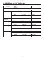
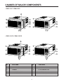
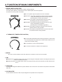
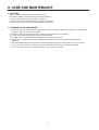
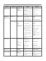
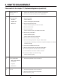
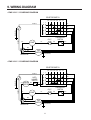
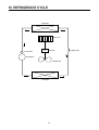
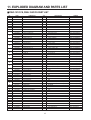
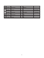
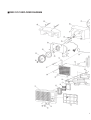
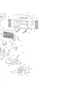
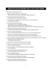
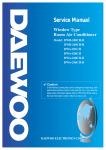
TABLE OF CONTENTS
1. PRECAUTION. . . . . . . . . . . . . . . . . . . . . . . . . . . . . . . . . . . . . . . . . . . . . . . . . . . . . . . . . . . . . . . . . . . . . . . . . . . . . . . 2
2. GENERAL SPECIFICATIONS . . . . . . . . . . . . . . . . . . . . . . . . . . . . . . . . . . . . . . . . . . . . . . . . . . . . . . . . . . . . . . . . 3
3. NAMES OF MAJOR COMPONENTS . . . . . . . . . . . . . . . . . . . . . . . . . . . . . . . . . . . . . . . . . . . . . . . . . . . . . . . . . 4
4. FUNCTION OF MAIN COMPONENTS . . . . . . . . . . . . . . . . . . . . . . . . . . . . . . . . . . . . . . . . . . . . . . . . . . . . . . . . 5
5. GENERAL INFORMATIONS . . . . . . . . . . . . . . . . . . . . . . . . . . . . . . . . . . . . . . . . . . . . . . . . . . . . . . . . . . . . . . . . . 6
6. CARE AND MAINTENANCE . . . . . . . . . . . . . . . . . . . . . . . . . . . . . . . . . . . . . . . . . . . . . . . . . . . . . . . . . . . . . . . . . 7
7. TROUBLE SHOOTING GUIDE . . . . . . . . . . . . . . . . . . . . . . . . . . . . . . . . . . . . . . . . . . . . . . . . . . . . . . . . . . . . . . . 8
8. HOW TO DISASSEMBLE . . . . . . . . . . . . . . . . . . . . . . . . . . . . . . . . . . . . . . . . . . . . . . . . . . . . . . . . . . . . . . . . . . . 10
9. WIRING DIAGRAM . . . . . . . . . . . . . . . . . . . . . . . . . . . . . . . . . . . . . . . . . . . . . . . . . . . . . . . . . . . . . . . . . . . . . . . . . 11
10. REFRIGERANT CYCLE . . . . . . . . . . . . . . . . . . . . . . . . . . . . . . . . . . . . . . . . . . . . . . . . . . . . . . . . . . . . . . . . . . . 12
11. EXPLODED DIAGRAM AND PARTS LIST . . . . . . . . . . . . . . . . . . . . . . . . . . . . . . . . . . . . . . . . . . . . . . . . . . 13
1
1. PRECAUTION
Please observe the following instructions.
1. Turn off unit.
Make sure the unit is OFF and the AC cord is unplugged before repairing or servicing.
2. In case of checking the circuit unavoidably while the unit is connected with power source, be careful
not to connect with the part of electric charge.
You may cause electric shock.
3. Use of proper part if you need to replace the part, be sure to use genuine part of servicing model.
Do not repair or replace the electric contact part.
Consumer must not repair the unit, because it is dangerous.
4. Use of proper tool.
You must use the proper tool to repair the unit, and use the measuring appliance adjusted accurately.
5. Damage of electric wire and power cord when servicing.
Check electric wire and a surely replace a damage electric wire and a damage power cord.
6. Never use connecting the middle of wire, after cutting the middle of wire.
It may cause a fire and trouble.
7. Checking the insulation resistance.
After you complete the assembly of unit, surely check the insulation resistance.
Confirm that the insulation resistance of the power line and the ground terminal is over 30MΩ by measuring insulation
resistance.
8. Checking the ground.
After checking the ground, servicing it completely.
9. Checking the installation.
After checking the installation, servicing it completely.
10. Care children.
When servicing, do not make the children approach the air-conditioner.
2
2. GENERAL SPECIFICATIONS
MODEL
DWC-121C/CS
ITEM
Function
DWA-150C/CS
Cooling only
Power source
AC 115V, 60Hz Singte Phase
AC 220V, 60Hz Singte Phase
Btu/h
12,100 Btu/h
14,300 Btu/h
Kcal/h
3,050 Kcal/h
3,604 Kcal/h
Btu/wh
10.1 Btu/wh
9.8 Btu/wh
Kcal/wh
2.55 Kcal/wh
2.47 Kcal/wh
Pts/h
2.36 Pts/h
3.04 Pts/h
Power Input
1,172 W
1,460 W
Running Current
11A
6.6A
Cooling Capacity
Energy Efficiency Ratio
Dehumidification
Electrical Data
Type
Compressor
Rotary
Model
QK164CN12
QJ196KC23
Capacitor
40µF-370VAC
25µF-370VAC
Model
AM12DIOD10
AM12 DIOD11
Capacitor
12µF-370VAC
4µF-370VAC
Motor
Indoor-Fan
Blower-Fan
Outdoor-Fan
Propeller-Fan
Unit(W x H x D)
23.6(W) x 14.9(H) x 21.0(D) Inch (600(W )x 380(H) x 535(D) mm)
PACKING(W x H x D)
26.1(W) x 18.1(H) x 22.6(D) inch (663(W )x 460(H) x 573(D) mm)
Net Weight
88 lbs (38.8Kg)
92 lbs (42Kg)
Gross Weight
89 lbs (40.3 Kg)
96 lbs (43.5Kg)
Dimensions
Weight
3
3.NAMES OF MAJOR COMPONENTS
• DWC-121C / DWA-150C
9
3
3
10
1
7
11
7
1
4
4
8
2
5
8
2
5
6
6
• DWC-121CS / DWA-150CS
9
3
3
10
7
11
1
7
1
4
4
8
2
5
8
2
5
6
12
6
12
NO
PART NAME
NO
1
AIR FILTER
7
BLADE HORIZENTAL
2
GRILL FRONT
8
AIR VENT
3
CABINET
9
PLATE WINDOW TOP
4
BLADE VERTICAL
10
FRAME WINDOW KIT
5
KNOB THERMOSTAT
11
SHUTTER WINDOW
6
KNOB SELECTOR
12
AUTO LOUVER S/W (DWC-121CS/DWA-150CS)
4
PART NAME
4. FUNCTION OF MAIN COMPONENTS
1. ROTARY SWITCH (SELECTOR)
Please refer to the part of selector in the chapter 9 (Wiring Diagram).
The rotary switch (selector) controls the fan motor’s rotation speed, and has six positions.
The function of the six position is as follow.
●OFF: This position stops all operations of the air conditioner.
●HIGH COOL: This position provides the maximum air flow for rapid
cooling, dehumidifying and dust removing operations.
(Use this position on sultry summer days.)
●MED COOL: This position proride the edium air flow for cooling
dehumidifying and dust remoring operations
●LOW COOL: This position provides the minimum air flow for quiet
cooling, dehumidifying operations.
(Use this position on suitable for night-time.)
●HIGH FAN: This position provides the maximum air fiow alone fan
operation without cooling operation.
●LOW FAN: This position provides the minimum air flow air flow alone
fan operation without cooling operation.
2. THERMOSTAT (TEMPERATURE CONTROL)
●The Thermostat automatically starts and stops operation in order to keep
the room temperature at a proper level, and this results in efficient use of
power and economical cooling.
●Turn clockwise for a cooler room temperature.
●Turn counter-clockwise for a warmer room temperature.
3. MOTOR
The motor is used to rotate the indoor and outdoor fan so that the room air can be recirculated.
4. FAN
●BLOEWR FAN: The Blower draws hot air from the room through the Evaporator and then discharges it back into the
cool air. It circulates the room air.
●PROPELLER FAN: The propeller draws outdoor air through louvering and cools Condenser, and then blows the hot
air out.
5. CAPACITOR
The Capacitor enlarges the difference of phase between main coil and sub coil so that the Compressor and Fan Motor
starts well.
6. ACCUMULATOR
The Accumulator blocks the unflow of liquid refrigerant and impurities into the Compressor.
5
5. GENERAL INFORMATIONS
1. CHANGING AIR FLOW DIRECTION
Air flow deflectors divert air from center flow to left or right.
Adjust deflectors for desired air flow pattern.
2. AIR FLOW AROUND UNIT
Check in door grill and outdoor louvers for air flow obstructions. Do not block air flow to and from unit. The outdoor coil
should be checked and periodically cleaned for debris that may collect and block unit air flow. If air flow is obstructed
or deflected back into unit, the compressor may cycle on and off rapidly, causing early compressor failure.
3. Electrical Grounding Instructions.
This appliance is equipped with a three-prong(grounding) plug for protection against possible shock hazards. If a twoprong wall receptacle is encountered, the customer is required to contact a qualified electrician and have the twoprong wall receptacle replaced with a properly grounded three-prong wall receptacle in accordance with the National
Electrical Code.
4. USE OF EXTENSION CORDS
Because of potential safety hazards under certain conditions we strongly recommend against the use of an extension
cord. However, if you still elect to use an extension cord, it is absolutely necessary that it be a UL listed 3-wire
grounding type appliance extension cord rated has a 3-blade grounding plug and a 3-slot receptacle that will plug into
appliance. The marked rating of the extension cord should be 115V 13A, 220V 10A or more.
5. DRAIN HOLE AND WATER DRIPPING OUTSIDE
Locate drain hole at the rear of unit. Water in base pan is picked up by the fan blade and thrown onto the warm
outdoor coil where it evaporates. The air conditioner must be installed level or tited or slightly to the outside for proper
water disposal. On exceptionally hot and humid days the air conditioner may permit excess water to pass thru rear
drain hole or overflow. This should be considered normal.
6
6. CARE AND MAINTENANCE
1. AIR FILTER
Clean the air filter, which removes dust inside the room.
It should be washed at least once every week during operation.
1. Remove the Air Filter from the front grill by pulling up.
2. Clean Air Filter with a vacuum cleaner or lukewarm, soapy water.
3. Shake it when clean to remove moisture completely. Replace it.
2. CLEANING THE AIR CONDITIONER
1. At least once a year, remove cabinet and thoroughly clean air conditioner. Have the unit inspected by an authorized
servicer to ensure unit is functioning properly.
2. Wash air conditioner with lukewarm, soapy water as needed. Rinse and dry thoroughly.
3. If using concentrated liquid detergent, dilute in warm water first.
4. Front grill may be wiped off with a cloth dampened in a mild detergent solution.
5. Cabinet may be washed with mild soap or detergent and lukewarm water, then polished with liquid wax for
appliances.
6. Condenser and Evaporator coils should be cleaned at the beginning of each cooling season. Use a soft brush or
vacuum cleaner to clean them, making sure that the Condenser and Evaporator coils are not damaged.
7. Do not use abrasive cleaners. These items scratch, crack and discolor surfaces.
7
7. TROUBLE SHOOTING GUIDE
TROUBLE
Fan motor and
compressor do not
run
SITUATION
1. Power failure
ANALYSIS
CAUSE
REMEDY
1) Power plug
1) Power failure
●Consult your electric company
2) Circuit breaker
2) Circuit breaker is tripped
●In case of a breaker, turn it on
and off a few times
3) Power plug is not contacting
●Replace the power plug
2. Power is supplied,
but the equipment
does not run
1) receptacle
●Disconnection
2) Operation switch
●Mechanical failure of switch
3) Cord or lead wire to
the switch
1) Disconnection
●Repair or replace the
receptacle
●Replace the cord or lead wire
2) Malfunction of contact
Switch is in “cool”
position but the
compressor does not
run
1. Not operating at all
1) Compressor
●Disconnection or burned-out
2) Thermostat
1) Failure
●Replace the compressor or
connection wire
●Replace
2) Malfunction
●Repair or replace
3) Knob is not set to the proper
setting
3) Selector switch
●Failure of malfunction of
proper setting
4) O.L.P
1) Disconnection
●Turn knob for cooler setting
●Repair or replace the swtting
●Repair
●Repair or replace
2) Malfunction of contact
●Replace
●Lack of capacity
●Disconnection
5) Capacitor
2. Compressor
1) The voltage exceeded allowed
range
1) Electricity
●Repair
●Consult your electric company
●Check the capacity of wire
2) Capacity of wire is not
sufficient
●Ventilate well and remove the
heat source
2) Room temperature
and outside
temperature
●Extremely high
●Burned-out
●Replace
3) Compressor
●Malfunction
●Replace
4) O.L.P
●Lack of capacity
●Replace
1) Thermostat
●Malfunction
●Replace
2) Capacitor
●Lack of capacity
●Replace
3) O.L.P
●Malfunction
●Replace
5) Capacitor
3. Frequent start and
stop
8
TROUBLE
SITUATION
The compressor runs
but the motor doesn’t
run
Both fan motor and
compressor are
running but cooling is
bad
Not cooling at all
Insufficient cooling
ANALYSIS
CAUSE
1) Fan
2) Fan motor
3) Capacitor
4) Fan motor circuit
●Blocked by others
●Repair
●Disconnection or burned-out
electric cord
●Replace the fan motor
●Failure malfunction of contact
●Replace
●Disconnection of malfunction
of contact
●Check the circuit
1) Refrigerant system is choked
●Repair
2) Compressor failure
●Repair
3) Leakage of refrigerant gas
●Recharge refrigerant gas
1) Refrigerant system
1) Refrigerant system is choked
●Check and repair refrigerant
system
2) Filter
2) Compressor failure
●Replace
3) Heat exchanger of
condenser
3) Leakage of refrigerant gas
●Check a part of Leakage and
repair
Refrigerant system
REMEDY
4) Refrigerant charge is too high
●Repair and recharge
●Clogged up with dust
●Clean the air fiter
1) Fin is cogged up with dust
●Clean the unit
2) The ventilation is not good
3) The unit is exposed to the
sunlight
●Shade the unit from the
sunlight
●Remove the added heat
source
4) Other heat source is added in
the room
Vibration & Noise
1) Installation place
●Installation of the unit is
imperfectly done
●Install the unit perfectly
2) Fan
1) Fan is contacted with
obstacles
●Remove obstacles
2) Fixing bolt
●Tighten the bolt
●Have a screw loose
●Tighten the screw
●Electrical noise
●Exchange the components
●The front is lower than rear
side
●Make rear side of the unit
lower than the front
1)Insulation defect of wiring and
lead wire
●Check the unit’s Leakage of
current.
2) Leakgae of current due to the
dew or rust
●Replace the defective parts or
components
3) Fixing screws
4) Electric
components
Water leakage into
room
Electric shock
(Leakage of current)
●Installation
condition
●Insulation of
components
9
8. HOW TO DISASSEMBLE
Please refer to the chapter 11 (Exploded diagram and parts list).
1
2
Before service of
1. Stop the unit, remove the power cord from the receptacles.
any part.
2. Move the unit to the safe location for the suitable work.
Ass’y Fan Motor
1. Remove Front Grill
- Fan Motor
- Remove Filter Pre.
- Propeller Fan
- Remove screw(2 point) in Front Grill.
- Blower Fan
2. Remove Cabinet from the unit.
- Remove screws (2 point) from the unit’s sides.
3. Remove Holder Screll.
4. Remove Scroll upper
- Remove screws (3 point) from Plate Scroll’s sides.
5. Remove Ass’y Control Box
- Remove screws (4 point).
- Remove wires in the each components.
6. Remove wires in the Panel Housing.
7. Remove screws (4 point) from Ass’y Fan Motor’s sides.
- Ass’y Fan Motor is assembly of Fan Motor, Propeller and Blower Fan, Orifice
and Panel Housing.
8. Lift the Ass’y Fan Motor from the unit.
9. Remove clip han (2 point) from the shaft of Fan Motor.
10. Remove Propeller Fan from the shaft of Fan Motor.
11. Remove Blower Fan from the shaft of Fan Motor.
12. Remove Fan Motor from Panel Housing.
- Remove screws (4 point).
3
Ass’y Control Box
1. Same as the procedure 1 to 5 in the Item 2.
- Rotary Switch (selector)
- Thermostat
- Capacitor
- Power Cord
4
O.L.P
1. Same as the procedure 1 to 2 in the Item 2.
2. Remove Terminal Cover from Compressor.
- Remove hex-nut (1 point).
10
9. WIRING DIAGRAM
• DWC-121C / CS WIRING DIAGRAM
SELECTOR SWITCH
HIGH MED LOW LOW MED
OFF COOL COOL COOL FAN FAN
1
GRN(GRN/YEL)
WHT(BLU)
7
6
YEL
4
RED
8
GRY
2
BLU
THERMOSTAT
SWITCH
DLK(BRN)
O.L.P
BLK
R
COMP
YEL
WHT
C
BLU
L
C
S
H
C
F
RED
ORG
FAN
MOTOR
BLK(BRN)
GRN(GRN/YEL)
CAPACITOR
• DWC-121C / CS WIRING DIAGRAM
SELECTOR SWITCH
HIGH MED LOW LOW MED
OFF COOL COOL COOL FAN FAN
1
GRN(GRN/YEL)
WHT(BLU)
SWING
MOTOR
BLK
AUTO
LOUVER
SWITCH
WHT
BRN
7
6
YEL
4
RED
8
GRY
2
BLU
THERMOSTAT
SWITCH
DLK(BRN)
O.L.P
BLK
R
COMP
YEL
WHT
C
L
S
H
C
F
RED
ORG
BLK(BRN)
CAPACITOR
FAN
MOTOR
BLU
GRN(GRN/YEL)
11
C
10. REFRIGERANT CYCLE
Evaporator
Blower fan
M
MOTOR
Accumulator
Compressor
Propeller fan
Condenser
12
Capillary tube
11. EXPLODED DIAGRAM AND PARTS LIST
■ DWC-121C/CS, DWA-150C/CS PART LIST
No.
CODE
1
3102402400
GRILL FRONT
1
HIPS
2
3103400700
KNOB
2
HIPS
3
3101600600
DECORATE FRONT
1
PC FILM
4
3101902100
FILTER PRE
1
HIPS
5
3106501800
BLADE VERTICAL
1
HIPS
6
3106501700
BLADE HORIZENTAL
2
PP
7
3108503600
SEAL GRILLE
1
F–US
8
3108100900
PAN BASE
1
SGCC T1.0
3107400800
ASS’Y EVAPORATOR
1
350X330.2(ø9.52 2R2C)
3107400810
ASS’Y EVAPORATOR
1
350X330.2(ø7 3R4C)
DWA-150C/CS(ONLY)
3104421100
PIPE EVA IN
1
C1220T–O OD9.52
DWC-121C/CS(ONLY)
9
10
11
12
13
14
15
17
18
19
Q’TY
SPECIFICATION
REMARK
DWC-121C/CS(ONLY)
3104421110
PIPE EVA IN
1
C1220T–O OD7
DWA-150C/CS(ONLY)
3100063600
PIPE EVA OUT AS
1
C1220T–O OD9.52
DWC-121C/CS(ONLY)
3100063610
PIPE EVA OUT AS
1
C1220T–O OD7
DWA-150C/CS(ONLY)
3104421700
PIPE EVA OUT 1
1
C1220T–O OD9.52
DWC-121C/CS(ONLY)
3104421710
PIPE EVA OUT 1
1
C1220T–O OD7
DWA-150C/CS(ONLY)
3104423100
PIPE SUNCTION
1
C1220T–O OD12.7
DWC-121C/CS(ONLY)
3104423110
PIPE SUNCTION
1
C1220T–O OD12.7
DWA-150C/CS(ONLY)
3100061600
PIPE CAPILLARY AS
1
C1220T–O ID1.6 L800
DWC-121C/CS(ONLY)
3100061610
PIPE CAPILLARY AS
1
C1220T–O
DWA-150C/CS(ONLY)
3107101190
COMP AS
1
LG–QK164CN12
DWC-121C/CS(ONLY)
–
16
COMPONENTS
3104425800
COMP AS
1
LG–QJ196KC23
DWA-150C/CS(ONLY)
PIPE DISCHARGE
1
C1220T–O OD7.94
DWC-121C/CS(ONLY)
3104425810
PIPE DISCHARGE
1
C1220T–O OD7.94
DWA-150C/CS(ONLY)
3100063500
PIPE COND OUT AS
1
C1220T–O OD7
DWC-121C/CS(ONLY)
3100063510
PIPE COND OUT AS
1
C1220T–O OD7
DWA-150C/CS(ONLY)
3100063400
PIPE COND IN AS
1
C1220T–O OD7
DWC-121C/CS(ONLY)
3100063410
PIPE COND IN AS
1
C1220T–O
DWA-150C/CS(ONLY)
3106800300
ASS’Y CONDESOR
1
515X341.5 (ø7 3R2C)
DWC-121C/CS(ONLY)
DWA-150C/CS(ONLY)
3106800310
ASS’Y CONDESOR
1
515X341.5 (ø7 3R2C)
3108504300
SEAL COND TOP
1
F–US
DWC-121C/CS(ONLY)
3108504300
SEAL COND TOP
1
F–US
DWA-150C/CS(ONLY)
20
3101202800
CLIP FAN
2
SK-5
21
3101802600
PAN BLOWER
1
ABS
22
3101404100
COVER MOTOR
1
EPS
23
3104202000
PANEL HOUSING
1
SGCC T1.0
24
3102000500
FIXTURE RUBBER
1
NBR
24-1
3100000010
BUSHING GUIDE
1
NBR
3108004900
MOTOR FAN
1
DAEWOO MOTOR (AM 12DWD10)
DWC-121C/CS(ONLY)
3108005100
MOTOR FAN
1
DAEWOO MOTOR (AM 12DWD11)
DWA-150C/CS(ONLY)
26
7007501211
SCREW HEX
4
SX12MFZN
27
3101802700
FAN PROPELLER
1
ABS + GF20%
28
3102201100
WINDOW KIT FRAME(L)
1
HIPS
29
3102201000
WINDOW KIT FRAME(R)
1
HIPS
30
3100604200
PLATE WINDOW TOP
1
SGCC T1.2
31
3100801400
CABINET AS
1
SGCC T0.8
32
3100604300
BRACKET WINDOW LOWER
2
SGCC T0.8
33
3100604500
BRACKET SILL
2
SGCC T1.6
34
3106600600
SCROLL LOWER
1
EPS
35
3103700100
LEVER VENT
1
PP
36
3103700100
WASHER VENT
1
PP
37
3104600100
RING VENT
1
NBR
38
3106700400
CAM
1
POM
DWC-121CS
39
5S10405620
S/W ROCKER
1
R19A–2(250VAC 6A)
DWA-150CS(ONLY)
40
3107000100
CLIP THERMO
1
ABS
19-1
25
13
No.
CODE
41
5SM0101700
THERMOSTAT AS
1
PFA 602GF
42
5S10405100
SWITCH ROTARY
1
SR6B41610D
43
3101300100
POWER CORD
1
16A 250V
3109503100
CAPACITOR
1
40uF/370VAC
DWC-121C/CS(ONLY)
3109503200
CAPACITOR
1
–
DWA-150C/CS(ONLY)
3101201600
CLAMP CAPACITOR
1
SGCC T0.6
3108004800
MOTOR SWING
1
120VAC 60Hz
3108002900
MOTOR SWING
1
220VAC 50/60Hz
47
3100508500
BOX CONTROL
1
SGCC T0.8
48
3106600500
SCROLL UPPER
1
EPS
49
3103002800
HOLDER SCROLL
2
SGCC
50
3104409300
PIPE RUBBER BUTYL
1
–
51
3102707500
HANESS COMP AS
1
UL1015–14,BLK,RED,WHT
52
3103200500
CAP DRAIN
1
ABS
44
45
46
COMPONENTS
Q’TY
14
SPECIFICATION
REMARK
DWC-121CS(ONLY)
DWA-150CS(ONLY)
■ DWC-121C EXPLODED DIAGRAM
1
5
DAEWOO ELECTRONICS CO., LTD.
686, AHYEON-DONG MAPO-GU SEOUL, KOREA
C.P.O. BOX 8003 SEOUL, KOREA
TELEX: DWELEC K28177-8
CABLE: “DAEWOOELEC”
FAX: 02) 590-6291
TEL: 02) 360-7114/590-6151~5
http://www.dwe. daewoo.co.kr
S/M NO.:
PRINTED DATE: JAN.1999
Service Manual
Window Type
Room Air Conditioner
Model: DWC-121C/121CS
DWA-150C/150CS
R
US
LISTED
ROOM AIR CONDITIONER
39WK
This instrument is listed by Underwriter’s
Laboratories, Inc. It is designed and manufactured to
meet rigid U.L. safety standards against X-radiation,
fire, casualty and electrical hazards.
DAEWOO ELECTRONICS CO., LTD.
VISION CREATIVE, INC.
`–‚
·ª
·Á
MODEL
„⁄ ∞¸ˆ¶
·º‚fi·‘
‡†·º„fi•˛ 5 ¡ 526
·º¿ ·” ø
1 6ˆ
TEL
DWC-121C/121CS DWA-150C/150CS
BUYER
¿ˇ
`⁄
`ƒ
˘˙
–‘
∞›
1´
99.1.12
6´
2´
99.1.20(…`⁄ )
7´
3´
99.4.22
8´
4´
9´
5´
1 0´
¿˛…‚
M E M O
¿‹¶Ùˆ‡
V I S I O N ·ª ·Á
`¶˙˝¿µ
TEL: 757-9340 FAX: 774-1039
-‚¯·” ˙
ˆ„ ¿¡
…›‰˜»
…”˙ ` ……¿
-
VISION CREATIVE, INC.
`–‚
·ª
·Á
MODEL
¿Ã–‚˙ˆ ∞œ¿Â·‘
‡†·º„fi•˛ 5 ¡ 526
·º¿ ·” ø
1 6ˆ
TEL
DWC-121C/121CS DWA-150C/150CS
BUYER
¿ˇ
`⁄
`ƒ
˘˙
–‘
∞›
1´
99.1.12
6´
2´
99.1.20(…`⁄ )
7´
3´
99.4.22
8´
4´
9´
5´
1 0´
¿˛…‚
M E M O
¿‹¶Ùˆ‡
V I S I O N ·ª ·Á
`¶˙˝¿µ
TEL: 757-9340 FAX: 774-1039
-‚¯·” ˙
ˆ„ ¿¡
…›‰˜»
…”˙ ` ……¿
-