1
Stereo - Amplifier
User’s Manual
1
2
Contents
1
Preface..........................................................................................4
1.1
Included.........................................................................................5
1.2
Transport .......................................................................................5
2
Overview control elements .........................................................6
2.1
Front panel ....................................................................................6
3
Overview connections .................................................................7
3.1
Back panel.....................................................................................7
4
Installation and power supply....................................................8
4.1
Placement ......................................................................................8
4.2
Mains connection ..........................................................................8
5
Inputs and outputs ....................................................................10
5.1
Inputs...........................................................................................10
5.2
Speaker terminals ........................................................................10
5.3
Bi-Wiring ....................................................................................11
5.4
Bridged operation........................................................................11
5.5
Audionet Link .............................................................................12
6
Operating ...................................................................................13
6.1
Powering up ................................................................................13
6.2
Switching on/off..........................................................................13
6.3
Using Audionet Link...................................................................13
7
Protection system ......................................................................14
8
Technical information...............................................................15
8.1
Construction ................................................................................15
8.2
Power supply...............................................................................15
9
Security advice...........................................................................16
10
Technical data ...........................................................................17
3
1
Preface
The Audionet AMP1 V2 is a stereo audio power amplifier of highest
performance and finish quality, and long-life stability. This system is
designed for absolute natural music reproduction.
The following will give you all information about how to operate your
AMP1 V2. Please read this carefully before the first use. Following these
instructions, your AMP1 V2 will give you long-lasting pleasure and satisfaction.
4
1.1 Included
Included you will find the following items:
·
the stereo power amplifier AMP1 V2
·
the user's manual (that you are currently reading)
·
one standard mains cord
1.2 Transport
Important
·
Please transport the AMP1 V2 only in the included package.
·
Always use the plastic bag to prevent scratches on the housing.
·
Please allow the AMP1 V2 to adapt to the climatic conditions in your
listening room before you switch on the unit for the first time after
transport.
5
2
Overview control elements
power
key
2.1 Front panel
6
7
Line (RCA) input right
Speaker terminal right
Audionet Link input
Audionet Link output
1
2
3
4
1
2
3 4
5
7
8
6
5
7
Line (RCA) input left
Speaker terminal left
Marking Mains phase
Mains input
6
8
3
Overview connections
3.1 Back panel
4
Installation and power supply
Important
·
For connecting or removing loudspeakers and/or the preamplifier your AMP1 V2 must be switched off to prevent damage
to the amplifier or the connected units.
·
Please make sure that all cables are in absolute best conditions!
Broken shields or short-cut loudspeaker cables could damage
speakers and/or amplifiers.
4.1 Placement
The compact design of the AMP1 V2 requires the unobstructed heat dissipation during operation. Please mind the following security notes:
Important
·
Please find a place for your Audionet AMP1 V2 that is sufficiently
ventilated to allow the heat to dissipate.
·
Do not expose the unit to direct sunlight or in close range to heat
sources like radiators or fan heaters.
·
Do not cover the ventilation slots of the unit.
4.2 Mains connection
The mains input 5 * is on the back panel of the AMP1 V2. To connect
the unit to mains use the included cord. If you prefer to use a different
power cord make sure they meet the specifications for your home country.
Important
·
The electrical specifications of your home country must meet the
electrical specifications printed onto the back panel.
·
The AMP1 V2 is a Class I unit and must be earthed. Please ensure a
stable earth connection. The Phase ('hot' pin) is marked 'PHASE' 6
on the back panel for the mains input.
*
see numbers in section 'Back panel' on page 7
8
·
Never pull the mains plug while the AMP1 V2 is switched on! Before
you pull the mains cord off the socket, power down the unit to standby mode.
Only in cases of extended absence (like vacations) or if massive trouble
on the mains power is to be expected you should remove the AMP1 V2
form the mains. To disconnect the unit completely from mains pull both
mains plugs.
Note
·
Using high-quality mains cords as the Audionet P10, may improve
the sound quality. Please consult your local Audionet dealer.
9
5
Inputs and outputs
Important
·
For connecting or removing loudspeakers and/or the pre amplifier your AMP1 V2 must be switched off to prevent damage to
the amplifier or the connected units.
·
Please make sure that all cables are in absolute best conditions!
Broken shields or short-cut loudspeaker cables could damage
speakers and/or amplifiers.
5.1 Inputs
The AMP1 V2 has two RCA inputs 1 and 8 for the connection of a pre
amplifier, e.g. Audionet PRE G2. Due to the dual mono construction, left
and right inputs are separated at the rear.
Please connect the right 1 and left input 8 of the AMP1 V2 to the corresponding outputs of your pre amplifier.
5.2 Speaker terminals
Connect your speakers to the gold plated terminals 2 and 7 on the back
panel of the AMP1 V2. You can use banana plugs or spades as well as
simple cable ends. In case you would like to bi-wire your speakers please
refer to section 'Bi-Wiring' on page 11.
Note
·
Look out for the correct connection of your speaker cables. Usually,
the terminals of your speakers are marked '+' and '-'. The AMP uses
the same marks.
·
Wrong speaker polarization will result in severe loss of sound quality!
Important
·
Although the AMP1 V2 has an effective protection system to prevent damage to the circuits, switch off the unit while working on
the speaker and/or audio cables.
10
Note
·
The nominal loudspeaker impedance should be 2 Ohms or higher.
·
Never use force or tools tightening the terminal screws.
5.3 Bi-Wiring
If your speakers support bi-wiring, use two separate cables to connect
each speaker to the output terminals 2 and 7 of the AMP1 V2. Impulse
response and spatiality may improve significantly.
Note
·
Again, please mind the correct polarization of the speakers!
5.4 Bridged operation
With a second AMP1 V2 bridged operation is possible (please refer to
technical information). In this case, every amplifier supplies only one
loudspeaker. For that the output signal of the pre amplifier must be available in inverted form additionally (e.g. use the Audionet PRE G2).
For the left channel now please do the following:
Connect the normal signal of the left pre amplifier output to the left input
1 and the inverted signal to the right input 8 of the AMP I V2 supplying the left loudspeaker. Please make a solid connection (wire cross section of 4.0 mm²) between both (–) loudspeaker outputs. Now please connect the left loudspeaker to both remaining (+)-outputs (the positive input
of the loudspeaker to the (+) output of the left channel).
For connecting the right channel please do the corresponding with the
second amplifier.
Important
·
In bridged operation the loudspeaker impedance must be 4 ohms
or more.
11
5.5 Audionet Link
For your convenience, the AMP1 V2 can be controlled remotely by one
of Audionet's multi channel pre amplifiers (e.g. MAP or MAP 1) as well
as one of Audionet's stereo pre amplifiers (e.g. PRE G2, PRE 1 G3) using
the Audionet Link interface.
You only need a optical 'Toslink' cable to connect the Audionet Link
output of your Audionet pre amplifier to the Audionet Link input IN 3
of the AMP1 V2.
In case you would like to automatically switch on/off further Audionet
units in your system (e.g. a second AMP1 V2) using the Audionet Link
interface, please connect the Audionet Link output OUT 4 of your
AMP1 V2 to the Audionet Link input of the next Audionet unit (e.g.
power amplifier, tuner, CD player etc.) using a simple 'Toslink' cable.
Note
·
The 'switch on' signal is issued to any further Audionet units daisy
chained to the Audionet Link output of your AMP1 V2 with a little
delay to avoid all units switching on at the same moment, which
could cause an overload of your mains fuse.
12
6
Operating
6.1 Powering up
First of all, please make sure your AMP1 V2 is connected correctly to
your pre-amplifier, speakers and mains (see section 'Installation and
power supply' on page 8 and section 'Inputs and outputs' on page 10).
The AMP1 V2 is a stand-by unit. As soon as the amplifier is connected to
the mains, the unit is in stand-by mode
Only in cases of extended absence (like vacations) or if massive trouble
on the mains power is to be expected it is recommended to disconnect the
AMP1 V2 from mains.
Important
·
Never pull the mains cord while the AMP1 V2 is switched on!
Before you pull the mains plug, power down the unit to stand-by
mode first.
6.2 Switching on/off
To power up the AMP1 V2 from stand-by mode, press the power key on
the front panel. Now the AMP1 V2 is in normal operating mode.
If you would like to switch off the unit, please press the power key on the
front panel.
Note
·
If 'remote controlling' via Audionet-link is used, after switching off
the AMP1 V2 is always in stand-by operation with low power consumption. Only in case of longer absence the AMP1 V2 should be
disconnected from the power supply (mains unplugged).
6.3 Using Audionet Link
If your AMP1 V2 is connected to an Audionet pre amplifier via Audionet
Link, use the remote control of the pre amplifier to automatically switch
on/off the AMP1 V2 (and all other Audionet units also connected via
Audionet Link).
For setting up the necessary connections please refer to section 'Audionet
Link' on page 12.
13
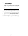
7
Protection system
Your AMP1 V2 has a powerful protection circuit to prevent damage of
the amplifier itself or the loudspeakers connected. In case of trouble the
AMP1 V2 is switched to stand-by state. The source of the problem is
indicated by a flash code of the LED next to the power key on the front
panel:
Error Code
Possible Cause
short short short
overload – left channel
short short long
overload – right channel
short long short
overheat – left channel
short long long
overheat – right channel
long short short
high frequency oscillation – left channel
long short long
high frequency oscillaiton – right channel
long long short
direct current (DC) – left channel
long long long
direct current (DC) – right channel
14
8
Technical information
8.1 Construction
The AMP1 V2 is constructed as a dual-mono amplifier. SMD techniques
are used to optimise high-frequency characteristics. All signal paths are
reduced to minimum length. No elements malicious to sound quality (i.e.
coupling capacitors, coils, relays) are located in the signal path. The construction is magnetically and capacitively optimised. Negative magnetic
and electric influence and interaction between input, decoupling and
power section are reduced to a residual minimum.
8.2 Power supply
The input sections are supplied by a 50 VA toroidal transformer with
separate windings for stereo channels. Two potted 700 VA toroidal transformers feed the power section. The control unit is supplied by separate
transformer.
The capacity of the fast and pulse-resistant high-current capacitors is
188,000 mF. The voltages are regulated with discrete and optimised ultra
high-speed MOSFET regulators.
15
9
Security advice
·
Avoid packaging material, especially plastic bags, to come into children’s hands.
·
Store and operate the unit in a dry room at a reasonable room temperature.
·
Avoid moisture or any liquid to get into the unit.
·
Set up the unit in a free position so that the air is allowed to flow
through the unit slits.
·
Do not cover, e.g. with a blanket.
·
Do not open the case. Unauthorised opening will cause loss of guarantee.
·
Use a dry cloth for cleaning.
16
10 Technical data
Function
Stereo power amplifier
Output Power
2 * 200 Watt into 8 Ohm
2 * 300 Watt into 4 Ohm
2 * 450 Watt into 2 Ohm
1 * 600 Watt into 8 Ohm (bridged)
1 * 900 Watt into 4 Ohm (bridged))
Frequency range
0 – 300.000 Hz (-3dB)
Damping factor
> 1000 @10 kHz
> 4000 @ 500 Hz
Intermodulation
< -110 dB SMPTE 100 Hz : 20 kHz, 4:1, 50 W/4 Ohm
THD+N
< -102 dB @1 kHz (35 Watt / 2 Ohm)
Harmonic distortion
k2 typ. –120 dB @ 25 Watt into 4 Ohm
k3 typ. –123 dB @ 25 Watt into 4 Ohm
SNR
> 106 dB @ 10 Veff
Inputs
2 WBT RCA line, gold-plated
1 Audionet Link, optical
Input impedance
37 kOhm, 220 pF
Outputs
2 pair WBT-NextGen jacks, gold-plated
1 Audionet Link, optical (TosLink)
Mains
120 V or 230 V, 50..60 Hz
Power consumption
Stand-by < 1W, max. 1.500 W
Dimensions
Width:
Height:
Depth:
Weight
28 kg
Finish
Front: brushed aluminium, 10 mm
black anodized, white printing or
nature anodized, black printing
430 mm
175 mm
315 mm
Display: red or blue
Cover and heat sink: aluminium black anodized
Chassis: steel, black varnished, 2 mm
17
Features
-
Audionet ULA technology
-
dual-mono amplifier
-
magnetically and capacitatively optimized construction
-
signal paths are kept to a minimum
-
no capacitors and electromechanical components
in the signal path
-
completely DC coupled
-
separate power supply for input and power stage
-
2 toroid transformer, each with 700 VA
-
4 impulse-stable high-current capacitors with
filtering capacity totalling 188,000 uF
-
discrete, extremely fast and stable driver and
output stages
-
control unit for HF, DC, temperature rise and
overload
-
remote activation via Audionet Link (fibre optics
cable)
Errors and omissions excepted. Specifications and design are subject to changes without prior notice.
audionet is a trademark of Idektron GmbH & Co KG
Engineered and produced by:
Idektron GmbH & Co. KG, Herner Str. 299, Gebäude 6, 44809 Bochum, Germany
www.audionet.de
[email protected]
18